EP1844834A1 - Filter seating monitor - Google Patents
Filter seating monitor Download PDFInfo
- Publication number
- EP1844834A1 EP1844834A1 EP07251311A EP07251311A EP1844834A1 EP 1844834 A1 EP1844834 A1 EP 1844834A1 EP 07251311 A EP07251311 A EP 07251311A EP 07251311 A EP07251311 A EP 07251311A EP 1844834 A1 EP1844834 A1 EP 1844834A1
- Authority
- EP
- European Patent Office
- Prior art keywords
- sealing element
- housing
- sensor
- circuit
- operator
- Prior art date
- Legal status (The legal status is an assumption and is not a legal conclusion. Google has not performed a legal analysis and makes no representation as to the accuracy of the status listed.)
- Withdrawn
Links
- 238000004891 communication Methods 0.000 claims abstract description 13
- 238000000034 method Methods 0.000 claims abstract description 13
- 239000000463 material Substances 0.000 claims abstract description 11
- 230000006835 compression Effects 0.000 claims abstract description 9
- 238000007906 compression Methods 0.000 claims abstract description 9
- 239000004020 conductor Substances 0.000 claims abstract description 4
- 238000007789 sealing Methods 0.000 claims description 34
- 230000005540 biological transmission Effects 0.000 claims 1
- 238000001914 filtration Methods 0.000 abstract description 12
- 239000003566 sealing material Substances 0.000 abstract description 3
- 238000012544 monitoring process Methods 0.000 abstract description 2
- 239000007788 liquid Substances 0.000 description 3
- 238000011179 visual inspection Methods 0.000 description 3
- 239000011148 porous material Substances 0.000 description 2
- 238000009877 rendering Methods 0.000 description 2
- 230000009286 beneficial effect Effects 0.000 description 1
- 230000009977 dual effect Effects 0.000 description 1
- 230000000694 effects Effects 0.000 description 1
- 238000012986 modification Methods 0.000 description 1
- 230000004048 modification Effects 0.000 description 1
- 238000005096 rolling process Methods 0.000 description 1
- 238000012360 testing method Methods 0.000 description 1
Images
Classifications
-
- B—PERFORMING OPERATIONS; TRANSPORTING
- B01—PHYSICAL OR CHEMICAL PROCESSES OR APPARATUS IN GENERAL
- B01D—SEPARATION
- B01D35/00—Filtering devices having features not specifically covered by groups B01D24/00 - B01D33/00, or for applications not specifically covered by groups B01D24/00 - B01D33/00; Auxiliary devices for filtration; Filter housing constructions
- B01D35/14—Safety devices specially adapted for filtration; Devices for indicating clogging
-
- B—PERFORMING OPERATIONS; TRANSPORTING
- B01—PHYSICAL OR CHEMICAL PROCESSES OR APPARATUS IN GENERAL
- B01D—SEPARATION
- B01D46/00—Filters or filtering processes specially modified for separating dispersed particles from gases or vapours
- B01D46/42—Auxiliary equipment or operation thereof
- B01D46/429—Means for wireless communication
-
- B—PERFORMING OPERATIONS; TRANSPORTING
- B01—PHYSICAL OR CHEMICAL PROCESSES OR APPARATUS IN GENERAL
- B01D—SEPARATION
- B01D46/00—Filters or filtering processes specially modified for separating dispersed particles from gases or vapours
- B01D46/42—Auxiliary equipment or operation thereof
- B01D46/44—Auxiliary equipment or operation thereof controlling filtration
-
- F—MECHANICAL ENGINEERING; LIGHTING; HEATING; WEAPONS; BLASTING
- F16—ENGINEERING ELEMENTS AND UNITS; GENERAL MEASURES FOR PRODUCING AND MAINTAINING EFFECTIVE FUNCTIONING OF MACHINES OR INSTALLATIONS; THERMAL INSULATION IN GENERAL
- F16J—PISTONS; CYLINDERS; SEALINGS
- F16J15/00—Sealings
- F16J15/02—Sealings between relatively-stationary surfaces
- F16J15/06—Sealings between relatively-stationary surfaces with solid packing compressed between sealing surfaces
- F16J15/064—Sealings between relatively-stationary surfaces with solid packing compressed between sealing surfaces the packing combining the sealing function with other functions
-
- F—MECHANICAL ENGINEERING; LIGHTING; HEATING; WEAPONS; BLASTING
- F16—ENGINEERING ELEMENTS AND UNITS; GENERAL MEASURES FOR PRODUCING AND MAINTAINING EFFECTIVE FUNCTIONING OF MACHINES OR INSTALLATIONS; THERMAL INSULATION IN GENERAL
- F16J—PISTONS; CYLINDERS; SEALINGS
- F16J15/00—Sealings
- F16J15/16—Sealings between relatively-moving surfaces
- F16J15/32—Sealings between relatively-moving surfaces with elastic sealings, e.g. O-rings
- F16J15/3296—Arrangements for monitoring the condition or operation of elastic sealings; Arrangements for control of elastic sealings, e.g. of their geometry or stiffness
-
- B—PERFORMING OPERATIONS; TRANSPORTING
- B01—PHYSICAL OR CHEMICAL PROCESSES OR APPARATUS IN GENERAL
- B01D—SEPARATION
- B01D2201/00—Details relating to filtering apparatus
- B01D2201/34—Seals or gaskets for filtering elements
Definitions
- One such application in which compressible material is used to form a seal is in the area of pharmaceutical filtering.
- one or more filter elements typically are placed within a housing and a liquid is passed through the filter elements to remove certain unwanted particulates. Since the filtering operation typically is performed under pressure, it is imperative that the filter elements are airtight and/or watertight. Should the seal not meet these requirements, integrity failures may result, thereby rendering the filtered liquid unusable.
- an electrically conductive material is used as the sealing material.
- the resistance of this material is monitored, since it is well known that electrical resistance is a function of the compression or strain on the material.
- This activity can be performed using a variety of techniques.
- a circuit, affixed to, or integral with the gasket can be used.
- the circuit can be external to the gasket and be placed in contact with the gasket at a plurality of locations.
- a conductive (or partially conductive) o-ring or gasket can contact electrical leads embedded in the housing at a specific location when properly seated.
- one or more switches are installed in or on the nose of the filtering element. These switches engage when the filtering element is properly seated. This information can then be conveyed to the operator, such as via wireless communication.
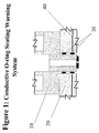
- FIG. 1 illustrates a representative filtering system in accordance with the present invention.
- the filter element 10 is enclosed within a housing 20.
- the filter element can be simply a porous material, such as pleated paper.
- the filter element may comprise a frame, such as of plastic, and a porous material.
- the filter element is in contact with the housing 20. This contact forms a seal and is preferably airtight and watertight.
- a gasket 30, such as an o-ring is used to provide such a seal.
- the gasket must be properly seated. As stated earlier, this is traditionally verified via visual inspection. This technique can be flawed and therefore, may not identify all of the improperly seated gaskets. Consequently, time and material is lost due to integrity failures caused by improperly seated gaskets. Therefore, an improvement increasing the likelihood of detecting a sealing failure would be beneficial.
- the first embodiment of the present invention includes an electrically conductive gasket. It is well known that materials change their conductivity under forces of compression. This is the basic theory employed in load cells. By utilizing this concept, it may be possible to determine whether the gasket is improperly seated. For example, a properly seated gasket would experience a certain amount of compression evenly distributed throughout. An improperly sealed gasket may have areas of no compression and other areas of increased compression, due to being rolled or twisted. The result would be that the overall conductivity of the gasket would be different than that of a properly seated one. This difference in conductivity would then alert the operator to visually inspect the seal, or to simply re-seat the gasket before continuing.
- the filter housing has two or more locations at which the gasket can be contacted.
- a circuit is located at a position exterior to the housing.
- the circuit generates a known voltage between the contact points.
- the circuit can measure the current flow between the contact points to determine the resistance of the gasket. This resistance can then be evaluated against acceptable ranges.
- the circuit can be designed to produce a constant current. In this scenario, the circuit measures the voltage difference between the contact points to determine the resistance.
- the housing is designed with a tapered end, into which the filtering element is placed.
- the circuit can also detect the relative position of the gasket within the tapered end. In other words, as the filtering element is pushed further into the tapered end, the compression force exerted on the gasket increases. Thus, the circuit is indirectly able to derive the location of the gasket within the tapered end of the housing.
- the ability to sense the conductivity would be integral with the gasket.
- a circuit capable of passing a known current through the gasket and recording the resulting voltage drop could be integrated into the gasket.
- a known voltage could be applied across the gasket and the resulting current could be recorded.
- the resistance of the gasket can be readily determined from these parameters.
- Other methods of computing the resistance of the gasket are well known in the art, and are within the scope of the present invention.
- the resulting value can then be communicated wirelessly to the operator, such as by using an RFID tag. This value can then be compared to a predetermined range, to determine that the gasket is properly seated.
- an open circuit is incorporated in the filter housing.
- an electrically conductive gasket is used.
- One or more electrical leads are incorporated in the head of the housing within which the filter is to be seated.
- the open electrical circuit within the housing is completed by the conductive gasket, since it is in direct contact with the electrical leads. This result is then used to alert the operator that the sealing element is properly seated.
- this embodiment performs a more simple connectivity test to verify that there is a conductive path between the electrical leads.
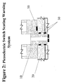
- one or more sensors 50 can be embedded in the nose of the filter. These switches would be engaged (i.e. closed) when the filter is properly seated through contact with the housing. Alternatively, these switches may be positioned within the housing, such that they are engaged when the sealing element is properly seated on them. These switches may be in contact with a wireless transmitter, such as an RFID tag. This allows their status to be wirelessly relayed to the operator. The operator can then use this information to determine whether it appears that the filter is properly seated. Alternatively, if the switches are positioned within the housing, the associated circuitry can be directly wired to them. In the manner described above, the operator is notified of the seating status.
- a wireless transmitter such as an RFID tag
Landscapes
- Engineering & Computer Science (AREA)
- General Engineering & Computer Science (AREA)
- Chemical & Material Sciences (AREA)
- Chemical Kinetics & Catalysis (AREA)
- Mechanical Engineering (AREA)
- Computer Networks & Wireless Communication (AREA)
- Investigating Or Analyzing Materials By The Use Of Electric Means (AREA)
- Examining Or Testing Airtightness (AREA)
Abstract
Description
- In many applications, it is necessary for one device to be seated atop or within another device. In many of these applications, the devices are required to form either an airtight or watertight seal. Examples of these types of applications include the interface between an automobile oil filters and the engine, the interface between a liquid container and its lid, and others. Traditionally, it is common practice to use a compressible material interposed between the devices to provide this seal. This compressible material may take many forms, such as but not limited to, gaskets, or 0-rings.
- One such application in which compressible material is used to form a seal is in the area of pharmaceutical filtering. In this application, one or more filter elements typically are placed within a housing and a liquid is passed through the filter elements to remove certain unwanted particulates. Since the filtering operation typically is performed under pressure, it is imperative that the filter elements are airtight and/or watertight. Should the seal not meet these requirements, integrity failures may result, thereby rendering the filtered liquid unusable.
- Traditionally, this risk is addressed via visual inspection. In other words, when the filtering element is seated, the operator visually checks that the sealing material, typically a dual o-ring, is properly positioned. However, since these seats are tight and require significant pressure to seal properly, at times the o-ring may appear properly seated when it is not, and in other cases, it may be difficult to view the entire circumference of the ring. Thus, while a visual inspection is helpful, it is unable to detect all sealing failures. Consequently, there are instances where integrity failures occur, thereby rendering the filtered results unusable.
- The present invention overcomes the shortcomings of the prior art by disclosing a method and apparatus for monitoring the integrity of seals, especially those in filtering elements. In one embodiment, an electrically conductive material is used as the sealing material. The resistance of this material is monitored, since it is well known that electrical resistance is a function of the compression or strain on the material. This activity can be performed using a variety of techniques. For example, a circuit, affixed to, or integral with the gasket can be used. Alternatively, the circuit can be external to the gasket and be placed in contact with the gasket at a plurality of locations. In a second embodiment, a conductive (or partially conductive) o-ring or gasket can contact electrical leads embedded in the housing at a specific location when properly seated. In a third embodiment, one or more switches are installed in or on the nose of the filtering element. These switches engage when the filtering element is properly seated. This information can then be conveyed to the operator, such as via wireless communication.
-
- Figure 1 illustrates a first embodiment of the present invention; and
- Figure 2 illustrates a second embodiment of the present invention.
- Figure 1 illustrates a representative filtering system in accordance with the present invention. The
filter element 10 is enclosed within ahousing 20. The filter element can be simply a porous material, such as pleated paper. Alternatively, the filter element may comprise a frame, such as of plastic, and a porous material. The filter element is in contact with thehousing 20. This contact forms a seal and is preferably airtight and watertight. In certain embodiments, agasket 30, such as an o-ring, is used to provide such a seal. For the seal to meet these requirements, the gasket must be properly seated. As stated earlier, this is traditionally verified via visual inspection. This technique can be flawed and therefore, may not identify all of the improperly seated gaskets. Consequently, time and material is lost due to integrity failures caused by improperly seated gaskets. Therefore, an improvement increasing the likelihood of detecting a sealing failure would be beneficial. - The first embodiment of the present invention includes an electrically conductive gasket. It is well known that materials change their conductivity under forces of compression. This is the basic theory employed in load cells. By utilizing this concept, it may be possible to determine whether the gasket is improperly seated. For example, a properly seated gasket would experience a certain amount of compression evenly distributed throughout. An improperly sealed gasket may have areas of no compression and other areas of increased compression, due to being rolled or twisted. The result would be that the overall conductivity of the gasket would be different than that of a properly seated one. This difference in conductivity would then alert the operator to visually inspect the seal, or to simply re-seat the gasket before continuing.
- In one embodiment, the filter housing has two or more locations at which the gasket can be contacted. A circuit is located at a position exterior to the housing. In one embodiment, the circuit generates a known voltage between the contact points. Thus, when the gasket is in place, the circuit can measure the current flow between the contact points to determine the resistance of the gasket. This resistance can then be evaluated against acceptable ranges. Alternatively, the circuit can be designed to produce a constant current. In this scenario, the circuit measures the voltage difference between the contact points to determine the resistance.
- In a modification to the previous embodiment, the housing is designed with a tapered end, into which the filtering element is placed. Thus, in addition to detecting seating errors caused by gasket rolling, the circuit can also detect the relative position of the gasket within the tapered end. In other words, as the filtering element is pushed further into the tapered end, the compression force exerted on the gasket increases. Thus, the circuit is indirectly able to derive the location of the gasket within the tapered end of the housing.
- In some instances, it may be difficult to provide a conduit through which the wires carrying the electrical signals can pass, especially if the gasket is contained within a housing. In another embodiment, the ability to sense the conductivity would be integral with the gasket. For example, a circuit capable of passing a known current through the gasket and recording the resulting voltage drop could be integrated into the gasket. Alternatively, a known voltage could be applied across the gasket and the resulting current could be recorded. As described above, in either case, the resistance of the gasket can be readily determined from these parameters. Other methods of computing the resistance of the gasket are well known in the art, and are within the scope of the present invention. The resulting value can then be communicated wirelessly to the operator, such as by using an RFID tag. This value can then be compared to a predetermined range, to determine that the gasket is properly seated.
- Alternatively, rather than incorporating a measuring circuit within the gasket, an open circuit is incorporated in the filter housing. As before, an electrically conductive gasket is used. One or more electrical leads are incorporated in the head of the housing within which the filter is to be seated. When the gasket, and therefore the filter, is properly seated, the open electrical circuit within the housing is completed by the conductive gasket, since it is in direct contact with the electrical leads. This result is then used to alert the operator that the sealing element is properly seated. Thus, rather than measuring the actual compression of the gasket, this embodiment performs a more simple connectivity test to verify that there is a conductive path between the electrical leads.
- In another embodiment, shown in Figure 2, one or
more sensors 50, such as but not limited to piezoelectric switches, can be embedded in the nose of the filter. These switches would be engaged (i.e. closed) when the filter is properly seated through contact with the housing. Alternatively, these switches may be positioned within the housing, such that they are engaged when the sealing element is properly seated on them. These switches may be in contact with a wireless transmitter, such as an RFID tag. This allows their status to be wirelessly relayed to the operator. The operator can then use this information to determine whether it appears that the filter is properly seated. Alternatively, if the switches are positioned within the housing, the associated circuitry can be directly wired to them. In the manner described above, the operator is notified of the seating status.
Claims (19)
- A method for insuring the proper seating of a sealing element, comprising:a. providing a conductive sealing element;b. providing a circuit adapted to measure the conductivity of said sealing element;c. utilizing said circuit to measure said conductivity; andd. determining whether said measured conductivity is within a predetermined range, wherein said predetermined range represents conductivity values of a properly seated sealing element.
- The method of claim 1, wherein said circuit is in communication with said sealing element through a plurality of contacts.
- The method of claim 1 or 2, wherein said sealing element is located within a housing and said circuit is either located outside of said housing, or located within said housing.
- The method of claim 1, 2 or 3, wherein said determination is transmitted to an operator.
- The method of claim 4, wherein said transmission is performed using wireless communication.
- A sealing element capable of alerting an operator of its seating status, comprising:a. a conductive material, having a known coefficient of conduction;b. a circuit in communication with said material, adapted to measure the conductivity of said material; andc. means for transmitting said status to said operator.
- The sealing element of claim 6, wherein said means for transmitting comprises wireless communication; and/or said means of transmitting comprises an RFID tag.
- The sealing element of claim 6 or 7, wherein said status either comprises said measured conductivity, or comprises an indication that said measured conductivity is within a predetermined range.
- A system for use with a housing, capable of alerting an operator of the seating status of a sealing element within said housing, comprising:a. said sealing element comprising a conductive material;b. a circuit;c. at least two leads embedded in an inner surface of said housing so as to contact said sealing element when seated and also in communication with said circuit; andd. means for transmitting said status to said operator.
- The system of claim 9, wherein said circuit produces a current between said leads and measures the voltage drop between said leads; and/or said circuit produces a voltage between said leads and measures the current between said leads.
- The system of claim 9 or 10, wherein said status is the measured conductivity of said sealing element.
- The system of claim 9, 10 or 11, wherein said housing comprises a tapered end into which said sealing element is placed, such that the compression of said sealing element increases as said sealing element is placed deeper into said tapered end.
- A method for insuring the proper seating of a sealing element within a housing, comprising:a. providing at least one sensor positioned between said sealing element and said housing so as to engage when said sealing element is properly seated;b. providing a circuit in communication with said at least one sensor to detect the state of said sensor;c. detecting the state of said at least one sensor; andd. alerting an operator of the seating status of said sealing element.
- A system for use with a housing, capable of alerting an operator of the seating status of a sealing element within said housing, comprising:a. said sealing element;b. at least one sensor positioned between said housing and said sealing element;c. a circuit in communication with said at least one sensor, so as to detect the state of said sensor; andd. means for transmitting said seating status to said operator.
- The system of claim 14, wherein said seating status is based on the state of said at least one sensor; and/or said at least one sensor is located on the inner surface of said housing.
- A method for insuring the proper seating of a sealing element between a filter element and a housing, comprising:a. providing at least one sensor positioned between said sealing element and said filter element so as to engage when said sealing element is properly seated;b. providing a circuit in communication with said at least one sensor to detect the state of said sensor;c. detecting the state of said at least one sensor; andd. alerting an operator of the seating status of said sealing element.
- The method of claim 13 or 16, whereby said alerting is performed by communicating said state of said at least one sensor to said operator; and/or wherein said communication is wireless; and/or wherein said communication is provided by an RFID tag.
- A system for use with a housing, capable of alerting an operator of the seating status of a sealing element located between a filter element and said housing, comprising:a. said sealing element;b. at least one sensor positioned between said filter element and said sealing element;c. a circuit in communication with said at least one sensor, so as to detect the state of said sensor; andd. means for transmitting said seating status to said operator.
- The system of claim 18, wherein said seating status is based on the status of said at least one sensor; and/or said at least one sensor is located on the outer surface of said filter element.
Priority Applications (1)
| Application Number | Priority Date | Filing Date | Title |
|---|---|---|---|
| EP08162711A EP2016989A1 (en) | 2006-04-12 | 2007-03-28 | Filter seating monitor |
Applications Claiming Priority (1)
| Application Number | Priority Date | Filing Date | Title |
|---|---|---|---|
| US11/402,530 US20070241510A1 (en) | 2006-04-12 | 2006-04-12 | Filter seating monitor |
Related Child Applications (1)
| Application Number | Title | Priority Date | Filing Date |
|---|---|---|---|
| EP08162711A Division EP2016989A1 (en) | 2006-04-12 | 2007-03-28 | Filter seating monitor |
Publications (1)
| Publication Number | Publication Date |
|---|---|
| EP1844834A1 true EP1844834A1 (en) | 2007-10-17 |
Family
ID=38197966
Family Applications (2)
| Application Number | Title | Priority Date | Filing Date |
|---|---|---|---|
| EP08162711A Withdrawn EP2016989A1 (en) | 2006-04-12 | 2007-03-28 | Filter seating monitor |
| EP07251311A Withdrawn EP1844834A1 (en) | 2006-04-12 | 2007-03-28 | Filter seating monitor |
Family Applications Before (1)
| Application Number | Title | Priority Date | Filing Date |
|---|---|---|---|
| EP08162711A Withdrawn EP2016989A1 (en) | 2006-04-12 | 2007-03-28 | Filter seating monitor |
Country Status (5)
| Country | Link |
|---|---|
| US (1) | US20070241510A1 (en) |
| EP (2) | EP2016989A1 (en) |
| JP (3) | JP2007286054A (en) |
| CN (1) | CN101073729A (en) |
| SG (1) | SG136868A1 (en) |
Cited By (4)
| Publication number | Priority date | Publication date | Assignee | Title |
|---|---|---|---|---|
| GB1288173A (en) * | 1970-05-12 | 1972-09-06 | ||
| EP2229994A3 (en) * | 2009-03-13 | 2010-11-03 | KNORR-BREMSE Systeme für Nutzfahrzeuge GmbH | Seal components with electronic components |
| GB2533275A (en) * | 2014-12-08 | 2016-06-22 | Skf Ab | A seal assembly as well as a method for monitoring a ring-shaped seal |
| WO2021099044A1 (en) * | 2019-11-20 | 2021-05-27 | Carl Freudenberg Kg | Seal assembly and seal element |
Families Citing this family (9)
| Publication number | Priority date | Publication date | Assignee | Title |
|---|---|---|---|---|
| US20070240578A1 (en) * | 2006-04-12 | 2007-10-18 | Dileo Anthony | Filter with memory, communication and temperature sensor |
| US8007568B2 (en) * | 2006-04-12 | 2011-08-30 | Millipore Corporation | Filter with memory, communication and pressure sensor |
| US20070243113A1 (en) | 2006-04-12 | 2007-10-18 | Dileo Anthony | Filter with memory, communication and concentration sensor |
| US20110094310A1 (en) * | 2006-04-12 | 2011-04-28 | Millipore Corporation | Filter with memory, communication and pressure sensor |
| US7731293B1 (en) * | 2008-12-22 | 2010-06-08 | Toyota Motor Engineering & Manufacturing North America, Inc. | Multiple part resin seat back with integrated adjustable headrest support |
| US10746014B2 (en) * | 2018-02-09 | 2020-08-18 | Schlumberger Technology Corporation | Method and system for monitoring a condition of an elastic element used in a downhole tool |
| US11779870B2 (en) | 2020-12-04 | 2023-10-10 | Mahle International Gmbh | Smart filter elements and systems |
| US12352355B2 (en) * | 2022-11-15 | 2025-07-08 | Goodrich Corporation | System and method for monitoring gasket sealing health |
| US12566210B2 (en) | 2023-07-07 | 2026-03-03 | Hamilton Sundstrand Corporation | System and method for testing an integrity of a face seal in an electrical system |
Citations (6)
| Publication number | Priority date | Publication date | Assignee | Title |
|---|---|---|---|---|
| US3698556A (en) * | 1970-10-30 | 1972-10-17 | Envirotech Corp | Apparatus for steam drying filter cake |
| US5581019A (en) * | 1992-07-16 | 1996-12-03 | W. L. Gore & Associates, Inc. | Gasket/insertable member and method for making and using same |
| EP1106962A2 (en) * | 1999-12-10 | 2001-06-13 | Bayerische Motoren Werke Aktiengesellschaft | Method and device for determining the relative position of two vehicle parts |
| US6615639B1 (en) * | 1992-02-25 | 2003-09-09 | Ralph Heinzen | Self monitoring static seal |
| WO2005031195A1 (en) * | 2003-09-29 | 2005-04-07 | Tokyo Electron Limited | Sealing ring and its managing system |
| US20050156487A1 (en) * | 2004-01-16 | 2005-07-21 | Taiwan Semiconductor Manufacturing Co. | Piezoelectric o-ring transducer |
Family Cites Families (52)
| Publication number | Priority date | Publication date | Assignee | Title |
|---|---|---|---|---|
| US2131509A (en) * | 1937-04-22 | 1938-09-27 | Arthur H Goepel | Coupling connection for pipe joints and method of making same |
| US4272109A (en) * | 1977-06-08 | 1981-06-09 | Vetco, Inc. | Ring gasket retainer for flanged connectors |
| DE3480588D1 (en) * | 1983-12-20 | 1990-01-04 | Hembrex Inc | FILTRATION METHOD AND DEVICE. |
| JPS63275877A (en) * | 1987-05-06 | 1988-11-14 | Yamatake Honeywell Co Ltd | Leakage detector for regulation valve |
| US5040805A (en) * | 1989-11-02 | 1991-08-20 | Oiles Corporation | Spherical sealing body used for exhaust pipe joint and manufacturing method thereof |
| JPH04361128A (en) * | 1991-06-07 | 1992-12-14 | Mitsui Petrochem Ind Ltd | Tool for airtight inspection |
| US5121929A (en) * | 1991-06-24 | 1992-06-16 | Fel-Pro Incorporated | Gasket with encased load sensor |
| US5246235A (en) * | 1992-02-25 | 1993-09-21 | Ralph Heinzen | Seal with embedded wire |
| US5540448A (en) * | 1992-02-25 | 1996-07-30 | Heinzen; Ralph | Seal with electrical conductor wear indicator |
| JPH0679147A (en) * | 1992-09-04 | 1994-03-22 | Fuji Photo Film Co Ltd | Filtration method |
| NL9300554A (en) * | 1993-03-29 | 1994-10-17 | Doctro A V V | Assembly of filter device and a replaceable filter; as well as filter device and filter for use therein. |
| DE69409736T2 (en) * | 1993-08-30 | 1998-10-01 | Millipore Invest Holdings | Testing the integrity of porous structures using sound emissions |
| DE9320143U1 (en) * | 1993-12-30 | 1995-04-27 | Nord, Klaus Jürgen, 68199 Mannheim | Device for controlling an electrical signaling device when impermissible movements of sealed shafts of technical devices occur |
| US5624537A (en) * | 1994-09-20 | 1997-04-29 | The University Of British Columbia - University-Industry Liaison Office | Biosensor and interface membrane |
| US5560278A (en) * | 1994-10-11 | 1996-10-01 | Caterpillar Inc. | Hydraulic cylinder with an electrical contacting and sealing ring |
| US6077435A (en) * | 1996-03-15 | 2000-06-20 | Usf Filtration And Separations Group Inc. | Filtration monitoring and control system |
| US5683119A (en) * | 1996-09-10 | 1997-11-04 | Metex Corporation | Pipe joint and seal therefor |
| JP3303722B2 (en) * | 1997-04-04 | 2002-07-22 | 三菱自動車工業株式会社 | Exhaust particulate removal device for internal combustion engine |
| JPH1151803A (en) * | 1997-07-31 | 1999-02-26 | Shibuya Kogyo Co Ltd | Apparatus for detecting liquid leakage of liquid valve |
| US6595523B1 (en) * | 1998-06-03 | 2003-07-22 | Ralph Heinzen | Self monitoring mechanical seal |
| US6485703B1 (en) * | 1998-07-31 | 2002-11-26 | The Texas A&M University System | Compositions and methods for analyte detection |
| US7283061B1 (en) * | 1998-08-28 | 2007-10-16 | Marathon Oil Company | Method and system for performing operations and for improving production in wells |
| US6333699B1 (en) * | 1998-08-28 | 2001-12-25 | Marathon Oil Company | Method and apparatus for determining position in a pipe |
| US20040239521A1 (en) * | 2001-12-21 | 2004-12-02 | Zierolf Joseph A. | Method and apparatus for determining position in a pipe |
| NL1010941C2 (en) * | 1998-12-31 | 2000-07-03 | Fairey Arlon Bv | Filter, in particular liquid filter, provided with a filter element with identification label. |
| JP2000230879A (en) * | 1999-02-09 | 2000-08-22 | Kubota Corp | Water pipe leak detection method and apparatus |
| US6265973B1 (en) * | 1999-04-16 | 2001-07-24 | Transguard Industries, Inc. | Electronic security seal |
| US6270651B1 (en) * | 2000-02-04 | 2001-08-07 | Abetif Essalik | Gas component sensor |
| US6471853B1 (en) * | 2000-11-22 | 2002-10-29 | Pti Technologies, Inc. | Prognostic health monitoring of fluidic systems using MEMS technology |
| JP4358507B2 (en) * | 2000-12-01 | 2009-11-04 | ミリポア・コーポレイション | Chemical process system with multi-functional barrier filter |
| WO2002071931A1 (en) * | 2001-03-09 | 2002-09-19 | Scimed Life Systems, Inc. | Medical slings |
| US6533926B2 (en) * | 2001-04-05 | 2003-03-18 | Fleetguard, Inc. | Filter cartridge with concentric circuit rings for data transmission |
| MXPA03010697A (en) * | 2001-05-21 | 2005-03-07 | Colder Prod Co | Connector apparatus and method for connecting the same for controlling fluid dispensing. |
| US7009409B2 (en) * | 2001-08-10 | 2006-03-07 | Davie Neil R | Determination of gasket integrity by capacitance measurement |
| US6652740B2 (en) * | 2001-09-10 | 2003-11-25 | Honeywell International Inc. | Pressure sensing fluid filter system |
| EP1436068B1 (en) * | 2001-10-09 | 2006-02-08 | Millipore Corporation | Automated fluid filtration system for conducting separation processes, and for acquiring and recording data thereabout |
| DE10151269B4 (en) * | 2001-10-17 | 2005-08-25 | Sartorius Ag | Method for monitoring the integrity of filtration plants |
| US7011758B2 (en) * | 2002-02-11 | 2006-03-14 | The Board Of Trustees Of The University Of Illinois | Methods and systems for membrane testing |
| US7638042B2 (en) * | 2002-02-15 | 2009-12-29 | 3M Innovative Properties Company | System for monitoring the performance of fluid treatment cartridges |
| DE10208600A1 (en) * | 2002-02-27 | 2003-09-04 | Mann & Hummel Filter | Ölqualitätsmeßeinrichtung |
| KR20030074855A (en) * | 2002-03-14 | 2003-09-22 | (주)와콘 | Liquid pipe for detecting water leakage and establishing method |
| CA2492959A1 (en) * | 2002-07-19 | 2004-07-15 | Smiths Detection-Pasadena, Inc. | Non-specific sensor array detectors |
| US7352771B2 (en) * | 2002-10-08 | 2008-04-01 | Colder Products Company | Data collision detection device and method |
| AU2003279926A1 (en) * | 2002-10-09 | 2004-05-04 | Cellectricon Ab | Method for interfacing macroscale components to microscale devices |
| US6917891B2 (en) * | 2003-02-28 | 2005-07-12 | Xerox Corporation | Systems and methods for diagnosing and predicting fluid flow systems using sensors |
| US7198303B2 (en) * | 2003-03-31 | 2007-04-03 | Metex Mfg. Corporation | Exhaust pipe joint and seal |
| US20050224577A1 (en) * | 2004-04-08 | 2005-10-13 | Rozenblat Gary D | Method and apparatus for automated identifying, monitoring the use of, and assessing the effective life span of process manufacturing components |
| US7100427B2 (en) * | 2004-05-07 | 2006-09-05 | Sensicore, Inc. | Multi-sensor system for fluid monitoring with selective exposure of sensors |
| US7264649B1 (en) * | 2004-07-23 | 2007-09-04 | Advanced Design Consulting Usa, Inc. | System for allergen reduction through indoor humidity control |
| GB0418011D0 (en) * | 2004-08-12 | 2004-09-15 | Cotton Martin | Seal arrangement |
| JP4317099B2 (en) * | 2004-08-12 | 2009-08-19 | 日本電信電話株式会社 | Leak sensor and leak detection system |
| US20070193361A1 (en) * | 2006-02-20 | 2007-08-23 | Davie/Coffee Technologies, LLC | Compressive load sensor by capacitive measurement |
-
2006
- 2006-04-12 US US11/402,530 patent/US20070241510A1/en not_active Abandoned
-
2007
- 2007-03-20 SG SG200701978-9A patent/SG136868A1/en unknown
- 2007-03-28 EP EP08162711A patent/EP2016989A1/en not_active Withdrawn
- 2007-03-28 EP EP07251311A patent/EP1844834A1/en not_active Withdrawn
- 2007-04-10 JP JP2007102715A patent/JP2007286054A/en active Pending
- 2007-04-12 CN CNA2007100968008A patent/CN101073729A/en active Pending
-
2009
- 2009-04-13 JP JP2009097133A patent/JP2009156880A/en not_active Abandoned
- 2009-04-13 JP JP2009097123A patent/JP2009156879A/en not_active Abandoned
Patent Citations (6)
| Publication number | Priority date | Publication date | Assignee | Title |
|---|---|---|---|---|
| US3698556A (en) * | 1970-10-30 | 1972-10-17 | Envirotech Corp | Apparatus for steam drying filter cake |
| US6615639B1 (en) * | 1992-02-25 | 2003-09-09 | Ralph Heinzen | Self monitoring static seal |
| US5581019A (en) * | 1992-07-16 | 1996-12-03 | W. L. Gore & Associates, Inc. | Gasket/insertable member and method for making and using same |
| EP1106962A2 (en) * | 1999-12-10 | 2001-06-13 | Bayerische Motoren Werke Aktiengesellschaft | Method and device for determining the relative position of two vehicle parts |
| WO2005031195A1 (en) * | 2003-09-29 | 2005-04-07 | Tokyo Electron Limited | Sealing ring and its managing system |
| US20050156487A1 (en) * | 2004-01-16 | 2005-07-21 | Taiwan Semiconductor Manufacturing Co. | Piezoelectric o-ring transducer |
Cited By (6)
| Publication number | Priority date | Publication date | Assignee | Title |
|---|---|---|---|---|
| GB1288173A (en) * | 1970-05-12 | 1972-09-06 | ||
| EP2229994A3 (en) * | 2009-03-13 | 2010-11-03 | KNORR-BREMSE Systeme für Nutzfahrzeuge GmbH | Seal components with electronic components |
| GB2533275A (en) * | 2014-12-08 | 2016-06-22 | Skf Ab | A seal assembly as well as a method for monitoring a ring-shaped seal |
| GB2533275B (en) * | 2014-12-08 | 2017-02-22 | Skf Ab | A seal assembly as well as a method for monitoring a ring-shaped seal |
| WO2021099044A1 (en) * | 2019-11-20 | 2021-05-27 | Carl Freudenberg Kg | Seal assembly and seal element |
| CN114729698A (en) * | 2019-11-20 | 2022-07-08 | 卡尔·弗罗伊登伯格公司 | Sealing device and sealing element |
Also Published As
| Publication number | Publication date |
|---|---|
| JP2007286054A (en) | 2007-11-01 |
| JP2009156880A (en) | 2009-07-16 |
| SG136868A1 (en) | 2007-11-29 |
| CN101073729A (en) | 2007-11-21 |
| EP2016989A1 (en) | 2009-01-21 |
| US20070241510A1 (en) | 2007-10-18 |
| JP2009156879A (en) | 2009-07-16 |
Similar Documents
| Publication | Publication Date | Title |
|---|---|---|
| EP2016989A1 (en) | Filter seating monitor | |
| CN105829850B (en) | Method for running pressure measure switcher and pressure measure switcher | |
| KR102081526B1 (en) | Pipe fitting with sensors | |
| JP6458044B2 (en) | Differential pressure sensor and manufacturing method thereof | |
| US10688422B2 (en) | Fluid quality monitoring and filtration system | |
| CN106907523B (en) | Method for predicting valve leakage | |
| JP2017506750A (en) | Package for differential pressure sensing die | |
| JP2017512307A (en) | Differential pressure detection die | |
| WO2018142102A1 (en) | System and method for monitoring a flange joint assembly | |
| US20110132816A1 (en) | Filter Provided with a Clogging Detector and an Assembly for Detecting the Presence of a Filtering Element Therein | |
| KR101452639B1 (en) | Differential pressure·pressure transmitter | |
| CN101821691B (en) | Apparatus for determining and/or monitoring process variable | |
| KR20080022081A (en) | Ball-and-socket joint with sensor device and method for detecting airtightness | |
| CN105393031A (en) | Diaphragm valve | |
| US20220403935A1 (en) | Seal assembly and seal element | |
| EP1425563B1 (en) | Pressure measuring apparatus | |
| CN118139922A (en) | Test fixtures and test equipment for rubber products, seals, and leak detection components | |
| CN110594020B (en) | Reason diagnostic system of crankcase high pressure | |
| KR101584682B1 (en) | Pressure sensing apparatus having self diagnosis | |
| US12436137B2 (en) | Systems and methods for membrane blockage detection in gas detectors | |
| JP4103028B2 (en) | Diaphragm seal type differential pressure measuring device | |
| CN112055608A (en) | Device and method for detecting wear of a separating element | |
| CN103108686B (en) | filter element | |
| WO2024132558A1 (en) | Pressure transducer | |
| JPH04131418U (en) | Hydraulic filter differential pressure indicating device |
Legal Events
| Date | Code | Title | Description |
|---|---|---|---|
| PUAI | Public reference made under article 153(3) epc to a published international application that has entered the european phase |
Free format text: ORIGINAL CODE: 0009012 |
|
| AK | Designated contracting states |
Kind code of ref document: A1 Designated state(s): AT BE BG CH CY CZ DE DK EE ES FI FR GB GR HU IE IS IT LI LT LU LV MC MT NL PL PT RO SE SI SK TR |
|
| AX | Request for extension of the european patent |
Extension state: AL BA HR MK YU |
|
| 17P | Request for examination filed |
Effective date: 20080115 |
|
| 17Q | First examination report despatched |
Effective date: 20080215 |
|
| AKX | Designation fees paid |
Designated state(s): AT BE BG CH CY CZ DE DK EE ES FI FR GB GR HU IE IS IT LI LT LU LV MC MT NL PL PT RO SE SI SK TR |
|
| STAA | Information on the status of an ep patent application or granted ep patent |
Free format text: STATUS: THE APPLICATION IS DEEMED TO BE WITHDRAWN |
|
| 18D | Application deemed to be withdrawn |
Effective date: 20100813 |