EP1844641A1 - Reel mower cutting unit - Google Patents
Reel mower cutting unit Download PDFInfo
- Publication number
- EP1844641A1 EP1844641A1 EP07105604A EP07105604A EP1844641A1 EP 1844641 A1 EP1844641 A1 EP 1844641A1 EP 07105604 A EP07105604 A EP 07105604A EP 07105604 A EP07105604 A EP 07105604A EP 1844641 A1 EP1844641 A1 EP 1844641A1
- Authority
- EP
- European Patent Office
- Prior art keywords
- reel
- bedknife
- motor
- adjustment
- cutting unit
- Prior art date
- Legal status (The legal status is an assumption and is not a legal conclusion. Google has not performed a legal analysis and makes no representation as to the accuracy of the status listed.)
- Granted
Links
- 238000005520 cutting process Methods 0.000 title claims abstract description 140
- 238000000034 method Methods 0.000 description 28
- 244000025254 Cannabis sativa Species 0.000 description 21
- 230000007246 mechanism Effects 0.000 description 11
- 230000000977 initiatory effect Effects 0.000 description 10
- 238000001514 detection method Methods 0.000 description 5
- 230000000712 assembly Effects 0.000 description 4
- 238000000429 assembly Methods 0.000 description 4
- 230000008859 change Effects 0.000 description 4
- 229920003023 plastic Polymers 0.000 description 3
- 239000004033 plastic Substances 0.000 description 3
- 230000009471 action Effects 0.000 description 2
- 238000010586 diagram Methods 0.000 description 2
- 230000000694 effects Effects 0.000 description 2
- 230000007613 environmental effect Effects 0.000 description 2
- 239000012530 fluid Substances 0.000 description 2
- 239000002184 metal Substances 0.000 description 2
- 238000012986 modification Methods 0.000 description 2
- 230000004048 modification Effects 0.000 description 2
- 230000008569 process Effects 0.000 description 2
- 238000005096 rolling process Methods 0.000 description 2
- 125000006850 spacer group Chemical group 0.000 description 2
- 238000009987 spinning Methods 0.000 description 2
- 229910001369 Brass Inorganic materials 0.000 description 1
- 230000003321 amplification Effects 0.000 description 1
- 230000003466 anti-cipated effect Effects 0.000 description 1
- 238000013459 approach Methods 0.000 description 1
- 230000005540 biological transmission Effects 0.000 description 1
- 239000010951 brass Substances 0.000 description 1
- 239000003990 capacitor Substances 0.000 description 1
- 230000006835 compression Effects 0.000 description 1
- 238000007906 compression Methods 0.000 description 1
- 230000003750 conditioning effect Effects 0.000 description 1
- 210000005069 ears Anatomy 0.000 description 1
- 238000003780 insertion Methods 0.000 description 1
- 230000037431 insertion Effects 0.000 description 1
- 238000012423 maintenance Methods 0.000 description 1
- 238000004519 manufacturing process Methods 0.000 description 1
- 238000003199 nucleic acid amplification method Methods 0.000 description 1
- 230000003287 optical effect Effects 0.000 description 1
- 229920002635 polyurethane Polymers 0.000 description 1
- 239000004814 polyurethane Substances 0.000 description 1
- 238000003825 pressing Methods 0.000 description 1
- 230000008439 repair process Effects 0.000 description 1
- 230000000630 rising effect Effects 0.000 description 1
- 230000035945 sensitivity Effects 0.000 description 1
- 230000003595 spectral effect Effects 0.000 description 1
- 229910001220 stainless steel Inorganic materials 0.000 description 1
- 239000010935 stainless steel Substances 0.000 description 1
- 239000012207 thread-locking agent Substances 0.000 description 1
- 238000004804 winding Methods 0.000 description 1
Images








Classifications
-
- A—HUMAN NECESSITIES
- A01—AGRICULTURE; FORESTRY; ANIMAL HUSBANDRY; HUNTING; TRAPPING; FISHING
- A01D—HARVESTING; MOWING
- A01D34/00—Mowers; Mowing apparatus of harvesters
- A01D34/01—Mowers; Mowing apparatus of harvesters characterised by features relating to the type of cutting apparatus
- A01D34/412—Mowers; Mowing apparatus of harvesters characterised by features relating to the type of cutting apparatus having rotating cutters
- A01D34/42—Mowers; Mowing apparatus of harvesters characterised by features relating to the type of cutting apparatus having rotating cutters having cutters rotating about a horizontal axis, e.g. cutting-cylinders
- A01D34/54—Cutting-height adjustment
-
- A—HUMAN NECESSITIES
- A01—AGRICULTURE; FORESTRY; ANIMAL HUSBANDRY; HUNTING; TRAPPING; FISHING
- A01D—HARVESTING; MOWING
- A01D34/00—Mowers; Mowing apparatus of harvesters
- A01D34/01—Mowers; Mowing apparatus of harvesters characterised by features relating to the type of cutting apparatus
- A01D34/412—Mowers; Mowing apparatus of harvesters characterised by features relating to the type of cutting apparatus having rotating cutters
- A01D34/42—Mowers; Mowing apparatus of harvesters characterised by features relating to the type of cutting apparatus having rotating cutters having cutters rotating about a horizontal axis, e.g. cutting-cylinders
- A01D34/62—Other details
Definitions
- the present inventors have recognized that the reel-to-bedknife adjustment is one such adjustment that needs to be adjusted accurately and precisely, but is often hard to achieve on individual mowing reels.
- the present inventors have recognized that the reel height-of-cut adjustment is another such adjustment that needs to be adjusted accurately and precisely, but is also difficult to adjust on individual mowing reels.
- the reel mower cutting unit may comprise a second adjustment actuator to adjust the height of cut of the reel cutting unit, the second adjustment actuator engageable manually in a manual adjustment mode, and engageable with the shaft of a second electric motor in a self-adjustment mode.
- the actuator may adjust a gap between the reel and the bedknife or a height of cut of the adjustable reel mower.
- extension of the rods 30c from the housings 30b, of the actuators 30, 32 lifts the inside frame 18 with respect to the outside frame 22.
- Retraction of the rod 30c into the housing 30b, of the actuators 30, 32 lowers the inside frame 18 with respect to the outside frame 22.
Landscapes
- Life Sciences & Earth Sciences (AREA)
- Environmental Sciences (AREA)
- Harvester Elements (AREA)
Abstract
Description
- The invention relates to a reel mower cutting unit comprising a reel and a bedknife; a first actuator to adjust a gap between the reel and bedknife and/or a second actuator to adjust a height of cut of the reel mower.
- Conventional mowing machines have an attached cutting reel unit or multiple units. Such machines typically move the cutting reel unit across the ground adjacent to the machine. Grass beneath the cutting reel unit is mowed as the machine travels forward. Conventional reel mower vehicles can include a plurality of arm members that extend from the vehicle, each arm having a cutting reel unit attached to its outer end portion.
- The cutting reel units typically include front and rear skids or rollers that support or carry the cutting reel unit across the surface of the ground during mowing operation. Such vehicles and cutting reel units are disclosed for example in
U.S. Patents 5,343,680 ;5,412,931 and5,459,984 . - Conventional cutting reel units provide a plurality of blades coupled together to form a generally cylindrical reel that rotates about a transverse axis. The blades pass in close proximity to a bedknife to create a scissoring action for cutting vegetation such as grass. A frame typically houses the reel and bedknife. Wheels, rollers or skids are coupled to the frame for engaging or rolling across the ground to operatively support the reel and bedknife at a predetermined height above the ground. The height at which grass is cut is therefore determined by the height at which the wheels, rollers or skids carry a frame, reel and bedknife above the ground. Cutting reel units are typically used for mowing golf courses or other areas were a relatively low and accurate cut is desirable.
- To produce a high quality cut, and a cut that is even for multiple cutting reel units and across mowing passes by a machine with multiple cutting reel units, it is necessary that the height-of-cut for each cutting reel unit be properly adjusted. It is known that reel mowers have an adjustment mechanism for adjusting the reel mowing height. One type of height adjustment mechanism utilizes a plurality of vertically aligned holes for a cutting unit frame. The rollers are coupled to a mounting member or plate that includes an opening. The mounting plate is coupled to the frame by insertion of a pin through both the mounting plate opening and one of the holes defined by the cutting unit frame. The cutting height can be varied by inserting the pin through a different hole in the frame. Other types of height adjustment mechanisms utilize threaded bolts which set the adjustment height using nuts engaged on the bolts and positionable to support a portion of the frame such that the cutting reel unit is held securely in the desired vertical position with respect to the rollers. A wrench is used to adjust the nuts to positions on the bolts to thereby adjust the cutting height.
- Another type of cutting reel unit utilizes a slotted mounting arm that is coupled with the rollers. A bolt received by the slot is used to adjust the height by loosening the bolt and shifting the slide-mounting arm to a new position.
- For all height-of-cut adjustments, there is a generally accepted and common method for determining a cutting reel unit's existing height-of-cut and how far it needs to be adjusted towards a targeted adjustment. The procedure for setting the cutting height typically involves fastening a gauge bar to the bedknife such that the upper surface of the bar is parallel to a forward, horizontal position of the bedknife and at the desired distance below the cutting edge of the bedknife. The front and rear rollers are then adjusted to come into contact with the upper surface of the gauge bar.
- The adjustment relationship between the front and rear rollers - relative to the cutting reel itself - is often termed the 'angle of attack' for the bedknife. This relationship refers to the relative pitch (front to back) or angle of the bedknife in relation to the ground surface. The angle of bedknife attack is an important parameter which affects the cut quality and effectiveness. Varying the height-of-cut must take the angle of attack into consideration.
- Cutting reel units cut properly only if the reel-to-bedknife clearance is properly adjusted. Currently, the reel-to-bedknife clearance is manually adjusted. The adjustment is made on a regular basis, typically before use, or made during or after use when poor cut quality is detected. Sometimes the adjustment is made such that the reel touches the bedknife and then the reel and bedknife are allowed to wear into place. Adjustments are also made after repair or replacement of the reel or bedknife.
- Specifically, the reel-to-bedknife clearance is adjusted by moving the reel away from the bedknife to allow a specific gap - that is even across the length of the reel and bedknife - between both the reel and bedknife. The gap is then measured by inserting a feeler gauge (of the same thickness as the adjustment gap) between the reel and bedknife. The adjusted gap between the reel and bedknife is determined to be accurate when the feeler gauge can be moved smoothly between the reel and bedknife across the entire length of the reel and bedknife, such that there is only a slight drag of the feeler gauge as it is moved across this length. To verify reel and bedknife sharpness and a correct reel-to-bedknife adjustment, a single strip of paper is often inserted between the reel blade and bedknife while the reel is turned forward by hand. If the reel cuts the paper, the sharpness and adjustment are usually determined to be correct. The quality of the cut of the piece of paper across the single sheet can be examined to indicate whether the clearance is correct.
- Reel adjustments are also necessary when a cutting reel unit is "re-tasked," in effect, adjusted for cutting another type of grass or grass to be cut to a different height. For example, a cutting reel unit could be re-tasked from an adjustment appropriate for a golf course fairway to adjustment appropriate for a golf course green, the two areas having different grass height requirements. However, re-tasking a cutting reel unit is time-consuming. To avoid re-tasking cutting reel unit, many golf courses have cutting reel units or cutting machines which remain designated or pre-adjusted for particular grass requirements, in effect, a designated group of cutting units for different areas of the golf course. This technique necessitates multiple cutting units or cutting machines. Multiple cutting units or machines can result in higher capital costs and maintenance costs.
- The present inventors have recognized that the cut quality of a reel mower is largely determined by the accuracy and precision of adjustment of several key factors. The present inventors have recognized that proper mower adjustments are often hard to achieve through manual adjustment methods.
- The present inventors have recognized that the reel-to-bedknife adjustment is one such adjustment that needs to be adjusted accurately and precisely, but is often hard to achieve on individual mowing reels. The present inventors have recognized that the reel height-of-cut adjustment is another such adjustment that needs to be adjusted accurately and precisely, but is also difficult to adjust on individual mowing reels.
- The present inventors have recognized that the accuracy and precision of these adjustments can be improved through automated adjustments.
- The present inventors have recognized that a need exists for dynamic adjustment capability for multi-area mowers or mowers that are capable of mowing multiple areas having different cutting requirements. The present inventors recognize that a need exists to be able to re-task a cutting reel unit dynamically to allow a single machine to mow multiple area types with different cutting reel unit setup requirements.
- The present inventors have recognized the need to also modulate reel speed, to provide reel-to-bedknife contact detection, and to make cutting reel unit adjustments during operation of the cutting reel unit.
- The present inventors have recognized the need to improve the adjustment process to ensure a shorter required time, ease of adjustment, and improved reel operation quality.
- It is therefore an object of the present invention to provide a reel mower cutting unit overcoming one or all of these needs respectively.
- This object is met according to the invention by the teaching of
claim 1, while features developing the solution in an advantageous way are set forth in the further claims. - The reel mower cutting unit may be manual or self-adjusting. Adjustments to reel-to-bedknife gap and/or height-of-cut may be performed in either a manual adjustment mode or a self-adjustment mode. In the manual mode, adjustments involve engaging and turning an adjustment actuator on the side of the cutting reel with a hand tool such as a socket wrench. In the self-adjustment mode, adjustments involve engaging and turning adjustment actuators with an output shaft of an electric motor. The same adjustment actuators are used in both adjustment modes. The reel cutting unit may be converted between the manual and self-adjustment modes by fastening or unfastening motor assembly from the unit. The motor assembly may be electric.
- An adjustment mechanism for a reel mower having a reel and a bedknife may comprise a first actuator to adjust a gap between the reel and bedknife; a second actuator to adjust a height of cut of the reel mower; a pair of motors mounted to the reel mower, each motor having a drive shaft engagable with one of the first and second actuators, the motors being removable such that the actuators can be manually engaged to adjust the reel-to-bedknife gap and height of cut.
- The adjustment mechanism may further comprise a motor mounting plate on which the pair of motors are mounted, the motor mounting plate removably fastenable to the reel mower.
- Each actuator may comprise an adjustment nut threaded to a first or upper end of a lead screw, each actuator optionally further comprising a follower threaded to a second or lower end of the lead screw.
- The adjustment mechanism may further comprise a position feedback sensor to detect the position of the motor, the position feedback sensor electrically connected to a controller.
- Each motor may include a socket on the end of an output shaft.
- A reel mower cutting unit according to the present invention may comprise a frame supporting a reel and a bedknife with a gap therebetween; an adjustment actuator to adjust the gap between the reel and bedknife, the adjustment actuator engageable manually in a manual adjustment mode, and engageable with the shaft of an electric motor in a self-adjustment mode; the reel mower cutting unit being convertible from the manual to the self-adjustment mode by attaching the electric motor to the frame.
- The reel mower cutting unit may comprise a second adjustment actuator to adjust the height of cut of the reel cutting unit, the second adjustment actuator engageable manually in a manual adjustment mode, and engageable with the shaft of a second electric motor in a self-adjustment mode.
- Both electric motors may be attached to a motor mounting plate that may be removably mounted to the frame.
- The reel mower cutting unit may further comprise an adjustment nut on the upper end of the adjustment actuator.
- The reel mower cutting unit of claim may comprise a socket on an end of the electric motor to engage the adjustment nut in the self-adjustment mode.
- The reel may be movable and the bedknife may be fixed.
- Alternatively an adjustable reel mower according to the present invention having a reel and a bedknife may comprise an actuator including a lead screw and a rotatable adjustment nut on an end of the lead screw; a motor mounted to the adjustable reel mower and having a shaft with a socket adapted to engage the adjustment nut in a self-adjustment mode; the motor being removable from the adjustable reel mower to allow engagement of the adjustment nut in a manual adjustment mode.
- The adjustable reel mower may further comprise a second actuator including a lead screw and a rotatable second adjustment nut on an end of the lead screw; a second motor mounted to the adjustable reel mower and having a shaft with a socket adapted to engage the second adjustment nut in a self-adjustment mode; the second motor being removable from the adjustable reel mower to allow engagement of the second adjustment nut in a manual adjustment mode.
- The adjustable reel mower may further comprise a motor mounting plate on which the motors are mounted, the motor mounting plate removably fastenable to the adjustable reel mower.
- The actuator may adjust a gap between the reel and the bedknife or a height of cut of the adjustable reel mower.
- The adjustable reel mower may comprise a position feedback sensor to detect the position of the motor and/or a contact sensor to detect contact between the reel and the bedknife.
- The adjustable reel mower may comprise a pair of motors mounted on each side of the adjustable reel mower.
- A control system for a cutting reel unit may include a height-of-cut adjusting system and a reel-to-bedknife clearance adjusting system. The height-of-cut adjusting system may include a first frame; a second frame; a cutting reel supported by the second frame; a bedknife arranged adjacent to the cutting reel and supported by the second frame; at least one support element arranged to translate along the ground and arranged to support the first frame; and at least one first actuator connected between the first frame and the second frame and arranged to adjust the relative elevation of the second frame with respect to the first frame. The reel-to-bedknife clearance adjusting system includes at least one second actuator operatively connected between the reel and the second frame and a sound detector. The reel mower cutting unit may be manual or self-adjusting. In the manual mode, adjustments can be made by engaging and turning an adjustment actuator on the side of the cutting reel with a hand tool such as a socket wrench. In the self-adjustment mode, adjustments can be made by engaging and turning adjustment actuators with an output shaft of an electric motor. The same adjustment actuators are used in both adjustment modes, and the reel cutting unit may be converted between modes by fastening or unfastening electric motor assembly from the unit.
- The invention may provide a control system for adjusting the reel of a cutting reel unit. The cutting reel unit can be carried by, or attached to, a vehicle, such as a tractor, singularly or as one of a plurality of cutting reel units, or can be incorporated into a riding mower, a walking mower or a ride-on mower, also singularly or as one of a plurality of cutting reel units.
- The control system can control reel-to-bedknife clearance, height-of-cut, lateral leveling of the reel, and the reel rotational speed.
- The cutting reel unit control system can be implemented through a variety of control architectures such as distributed control or centralized control. The control protocol can be CAN, serial, or other control protocols.
- The cutting reel unit control system can be automatically self-adjusting, which periodically corrects the reel adjustments such as the reel speed, the height-of-cut, the reel lateral leveling, and the reel-to-bedknife clearance, or corrects the reel to bedknife clearance if contact between the reel and bedknife is sensed during operation.
- The cutting reel unit control system can be configured as a central controller or by controllers located at each cutting unit, or even by a local controller designated for each actuator. The cutting reel unit control system can be adjusted after operator or automatic initiation of an adjustment routine in a central controller or by operator or automatic initiation of control routines performed by controllers at each cutting unit or at each actuator.
- The cutting reel unit adjustment can be made by a controller external to the cutting unit, such as by a control unit that is used in a shop to re-adjust or re-task a cutting unit for a pre-selected grass condition or area and desired height-of-cut.
- Alternatively to operator initiation, the cutting reel adjustments can also be initiated by a controller or control units that is/are responsive to a sensor such as a height of grass sensor, or by a location sensor and/or sender on the cutting unit or cutting machine that communicates with an external ground-based system or a global positioning system (GPS). These systems, responsive to external conditions, along with the onboard control systems as described herein facilitate implementation of the control system in either a manned cutting machine or an autonomous cutting machine.
- For example, different areas of a golf course could be mapped electronically and preprogrammed into the onboard or remote controller and such controller could communicate with the external positioning system and thereafter adjust the actuators to adjust the cutting unit for the type of grass, the area, and desired cut lines for corresponding areas of the golf course.
- The apparatus of the invention may include a cutting reel, a frame supported on at least one support element that is supported on, and is movable along, the ground, and a housing supporting the cutting reel, the housing movably mounted on the frame. A bedknife is carried on the frame. An actuator has a first portion connected to the frame and a second portion connected to the housing, wherein a distance between the first and second portions is adjustable to set spacing between the reel and the bedknife, and including a motive mechanism that is activated to adjust the distance.
- The cutting reel can be one driven in rotation by one or more hydraulic motors, electric motors, by the traction drive of the mower machine or vehicle, or by other type drive.
- Two actuators can be used, one actuator located at each end of the reel, and the actuators each have a first portion connected to the frame and a second portion connected to one of two housings that support ends of the reel, wherein a distance between the first and second portions is adjustable, and including a motive mechanism that is activated to adjust the distance.
- According to another aspect of the invention, a control system for a cutting reel unit may include a first frame; a second frame; a cutting reel supported by the second frame; a bedknife arranged adjacent to the cutting reel and supported by the second frame; at least one support element arranged to translate along the ground and arranged to support the first frame; at least one first actuator connected between the first frame and the second frame and arranged to adjust the relative elevation of the second frame with respect to the first frame; at least one second actuator operatively connected between the reel and the second frame and arranged to adjust the clearance between the reel and the bedknife; and a controller signal-connected to the first and second actuators.
- The control system can further comprise position sensors that are signal-connected to the controller, the position sensors determining the precise elevation of the reel with respect to the at least one support element and determining the position of the reel with respect to the bedknife.
- The control system can include a sound detector arranged in close proximity to the bedknife to detect touching between the cutting reel when spinning and the bedknife.
- According to another aspect of the invention, an improved anti-backlash arrangement is provided for a linear actuator. The linear actuator may include a stepper motor that drives a lead screw that advances or retracts a rod from a housing. The anti-backlash arrangement includes an anti-backlash nut threaded on the lead screw and a spring. The spring is connected to an end of the rod and to the anti-backlash nut. The anti-backlash nut has a first surface abutting a second surface of the rod, the spring pressing the first and second surfaces together such that thread play between the rod and the lead screw is removed. The first and second surfaces are preferably conically shaped and nest together.
- The disclosed invention provides advantages in that the apparatus and method allow for rapid and automatic adjustment of the reel-to-bedknife gap without operator intervention following operator initiation of the adjustment. The reel can be adjusted in seconds. The method has speed and consistency advantages over manual adjustment, and does not require detection of poor cut quality or excess surface wear in order to perform the automatic adjustment.
- The disclosed invention provides advantages in that the apparatus and method allow for rapid and automatic adjustment of the height-of-cut of a reel of a cutting reel unit without operator intervention following operator initiation of the adjustment. The reel can be adjusted in seconds. The method has speed and consistency advantages over manual adjustment, and does not require detection of poor cut quality in order to perform the automatic adjustment.
- By making these adjustments automatically, the reel adjustment process may be accomplished more consistently without the presence of a skilled mechanic. The automated adjustment also provides the capability for the support of autonomous equipment.
- The control system allows a cutting reel unit to be rapidly re-tasked to cut different grass heights for different areas of a golf course. The system allows a single cutting reel unit to be readily usable for multiple golf course areas.
- Numerous other advantages and features of the present invention will be become readily apparent from the following detailed description of the invention and the embodiments thereof, from the claims and from the accompanying drawings wherein
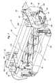
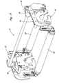
- Figure 1
- is a perspective view of a cutting reel unit according to the invention;
- Figure 2
- is a bottom perspective view of the cutting reel unit of Figure 1;
- Figure 3
- is a fragmentary sectional view taken generally along line 3-3 of Figure 1, with portions of the cutting unit removed for clarity of description, with the reel pivoted away from the bedknife;
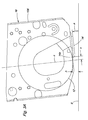
- Figure 3A
- is a schematic view of a reel position with respect to a bedknife position;
- Figure 4
- is a sectional view similar to Figure 3 with portions removed for clarity of description with the reel pivoted toward the bedknife;
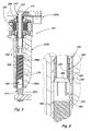
- Figure 5
- is a sectional view of an actuator as shown in Figure 3;
- Figure 6
- is an enlarged fragmentary sectional view of a portion of the actuator shown in Figure 5;
- Figure 7
- is a bottom perspective view of the components shown in Figure 4;
- Figure 8
- is a side view of the cutting unit shown in Figure 1 with portions removed for clarity of description wherein the reel is illustrated in an elevated operating position;
- Figure 9
- is a side view of the unit shown in Figure 1 wherein the reel is illustrated in a lowered operating position;
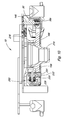
- Figure 10
- is a fragmentary, partial sectional view taken generally along offset line 10-10 of Figure 8;
- Figure 11
- is a perspective view of the unit shown in Figure 1 with the reel removed for illustrating underlying parts;
- Figure 12
- is a schematic diagram of a control system of the present invention;
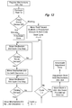
- Figure 13
- is a schematic block diagram illustrating a method according to the present invention;
- Figure 14
- is a fragmentary perspective view of an alternate embodiment with portions of the cutting unit removed for clarity of description; and
- Figure 15
- is a sectional view taken generally along line 15-15 of Figure 14.
- Figure 16
- is a side view of a manual or self-adjusting reel mower in a manual adjustment mode according to one embodiment of the invention;
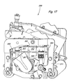
- Figure 17
- is a side view of a manual or self-adjusting reel mower in a self-adjustment mode according to one embodiment of the invention.
- While this invention is susceptible of embodiment in many different forms, there are shown in the drawings, and will be described herein in detail, specific embodiments thereof with the understanding that the present disclosure is to be considered as an exemplification of the principles of the invention and is not intended to limit the invention to the specific embodiments illustrated.
- Figures 1 and 2 illustrate a mower cutting
reel unit 10 according to the present invention. The mower cuttingreel unit 10 is adapted to be pulled alone or within a group of like units by a vehicle such as described inU.S. Patents 5,343,680 ;5,412,931 or5,459,984 , herein incorporated by reference. - A plurality of
blades 11 are coupled together to form a generallycylindrical reel 12 which rotates about a transverse axis in close proximity to anedge 14a of a bedknife 14 (Figure 2) for cutting vegetation, such as grass, with a scissoring action. Amotor 16, carried at one side of aframe 18 that generally houses and supports thereel 12, drives thereel 12. Themotor 16 can be a hydraulic, electric or other type motor. Alternatively, a transmission arrangement between the traction drive of the machine or vehicle and the reel can be used to rotate the reel. A hydraulic motor is indicated in the figures. - The
inside frame 18 is carried by anoutside frame 22. Theoutside frame 22 is supported on front andrear rollers inside frame 18 is supported on theoutside frame 22 byactuators struts struts frame 42 is arranged between the inner andouter frames frame 42 includesvertical plates side plates 52, 54 of theouter frame 22 bypins 56, 58 residing inslots 52a, 54a. Theslots 52a, 54a are part of a mechanism which permits the reel to be pushed from the rear when rolling, and still touch down heel first when lowered. - A
crossbar 48 connects theside plates crossbar 48 to tow or push thecutting unit 10 along the ground during the cutting operation. - The
outside frame 22 also includesadjustable bracket members fasteners 66 to arespective side plate 52, 54. Thebracket members bracket members member 62a and ahorizontal member 62b. Themembers holes 68 wherein a registered pair of holes between the members is selectable to set a horizontal overall dimension of thebracket members unit 10 behind theroller 24. Theunit 10 is shown withholes 68 selected to set a maximum horizontal dimension of thebracket members front roller 24. With just thefront roller 24 used,different holes 68 would preferably be selected to set a minimum horizontal dimension of thebracket members Vertical portions members plates front support assemblies front roller 24. Thefront support assemblies -
Plates frame side plates rear support assemblies rear roller 26. Therear support assemblies - The
inside frame 18 includes side plates 106,106 connected together bycrossbars grass deflector plate 118 is arranged between thebars reel 12. The side plates each include afront flange 122. Atube 126 is welded to each of thefront flanges 122. Atube 132 is also welded to each of themembers 62b.Sleeve bearings 140 are fit into each tube and a pin, bolt orother fastener 142 is used to pivotally connect each of the angled struts 36 to a respective pair oftubes - Figure 3 illustrates right side components of the
unit 10. The left side components are configured in substantially the same, but mirror-image manner. Theactuators motor drive 30a, ahousing 30b, and anactuator rod 30c extending out of a bottom of thehousing 30b. Therod 30c extends or retracts vertically from thehousing 30b by a selected turning direction of themotor drive 30a. Thehousing 30b is fastened to therespective side plate 106 byfasteners 143. Therod 30c is pivotally fastened to theouter frame 22, particularly to the respective outerframe side plate 52 by a fastener orpin 146. - Thus, extension of the
rods 30c from thehousings 30b, of theactuators inside frame 18 with respect to theoutside frame 22. Retraction of therod 30c into thehousing 30b, of theactuators inside frame 18 with respect to theoutside frame 22. - The
struts 36, 36 (Figures 1 and 2) prevents excessive forward or rearward tipping of theinside frame 18 lifted or lowered at the rear thereof and ensures a substantially straight vertical lifting or lowering of theinside frame 18. The geometry of theframes actuators - Figure 3A illustrates schematically the
side plate 106 and an outline of thereel 12 wherein the height-of-cut "h" from grade "g" and an offset "x" from the reel centerline "c" are shown. The attack angle "a" is also shown. Effective guideline maximum attack angles "a" with respect to height-of-cut are:


The preferred embodiment of the invention satisfies these guidelines. - For the preferred embodiment, the table below sets forth the relative positioning of the profile of the
edge 14a with respect to the reel centerline "c" as theinside frame 18 is lifted through a range of height-of-cut "h" and tilted over a range on attack angles "a"."h" "a" "x" 10 mm 0.38 deg 6.95 mm 15 mm 0.81 deg 7.38 mm 20 mm 1.20 deg 7.77 mm 25 mm 1.55 deg 8.12 mm 30 mm 1.86 deg 8.43 mm 35 mm 2.13 deg 8.70 mm 40 mm 2.36 deg 8.93 mm 45 mm 2.56 deg 9.13 mm 50 mm 2.72 deg 9.29 mm 55 mm 2.86 deg 9.43 mm 60 mm 2.95 deg 9.52 mm 65 mm 3.02 deg 9.59 mm 70 mm 3.05 deg 9.62 mm 75 mm 3.06 deg 9.63 mm -
Actuators inside frame 18 adjacent opposite ends of thereel 12. As illustrated in Figures 3 and 4, the actuators each include amotor actuator 202a, ahousing 202b, and anactuator rod 202c. Thehousing 202b is fastened to therespective side plate 106 byfasteners 212. Therods reel bearing housings reel 12 at opposite ends of theinside frame 18. Eachrod 202c is pinned to a ball joint 220 that is fixed to therespective housing 216, by anelongated pin 226. - Each
reel bearing housing 216 is pinned to arespective side plate 106 by a pin orfastener 230. The extension or retraction of therods housings actuators reel bearing housings fasteners rods reel housings blades 11 can be brought closer to or further from the bedknife 14 (Figure 2), particularly, closer to or further from anedge 14a of thebedknife 14. - Each ball joint 220 is carried on the base pin 231 (Figure 10) that is fixed to the bearing
housing 216 by being threaded tightly to the bearing housing using a thread-locking compound such as a LOCTITE® thread-locking product. Thebase pin 231 extends through the bearing housing to slide through aslot 232 formed in theside plate 106. For each actuator 202, 204, an L-shapedspring 234 is fixed to therod 202c and presses against the ball joint 220 to bias therod 202c in the downward direction, to remove play within the ball joint 220. - Figures 5 and 6 illustrate a
typical actuator actuator 202. Theactuator 202 includes themotor drive 202a, thehousing 202b and therod 202c. Inside thehousing 202b there is a drive screw orlead screw 260 that is driven into rotation by astepper motor 266 of themotor drive 202a. Thelead screw 260, being an extension of amotor shaft 268, is rotated by thestepper motor 266. - The
rod 202c is a substantially hollow cylinder and includes arod end portion 274 fixed to arod body portion 276 by threaded mutual engagement. Thelead screw 260 extends substantially through thebody portion 276. Alead nut 280 is fixed to therod body portion 276. Thelead nut 280 can include anouter metal casing 282, such as brass, and aninner sleeve 284, such as plastic, having internal Acme threads engaged to corresponding external Acme threads on thelead screw 260. Thelead screw 260 can be stainless steel. Alternatively, the lead nut could be formed as a unitary part with therod body portion 276, such as both being formed of plastic or metal. - An
anti-backlash nut 288 is threaded onto thelead screw 260. Theanti-backlash nut 288 also includes Acme threads, preferably plastic, and engaged to the external threads of thelead screw 260. Theanti-backlash nut 288 includes a convex conicaltapered surface 290 which abuts a concave conicaltapered surface 292 of therod body portion 276 or the lead nut 286 fixed to therod body portion 276. - A
coil spring 296 surrounds thelead screw 260. Thecoil spring 296 is connected to the anti-backlash nut at oneend 296a and to therod end portion 274 at anopposite end 296b. - The anti-backlash feature of the invention is provided by the resilient force of the
anti-backlash nut 288 urged in rotation around thelead screw 260 by thespring 296, against therod body portion 276 or lead nut 286. This force takes up all thread play between thelead screw 260 threads and thelead nut 280 threads. Theanti-backlash nut 276 and the lead nut 286 advance and retreat substantially together on thelead screw 260. - The inclination of the
surfaces lead nut 280 and theanti-backlash nut 276 or therod body portion 276, wherein the inclination is steeper than the inclination of the Acme threads of theanti-backlash nut 276 andlead screw 260. This causes theanti-backlash nut 276 to press against thelead nut 280 or therod body portion 276 sufficiently to remove play in the engaged threads, but will prevent theanti-backlash nut 276 andlead nut 280 from tightening excessively on thelead screw 260. - The
anti-backlash nut 288 and thespring 296 can be eliminated in theactuators actuators - The
motor drive 202a includeswindings 306, bearings 308, and anoptical encoder 310. Theencoder 310 includes atarget disk 312 and aread head 314. The readhead 314 includes two spaced-apart light emitting and reading devices, used to determine position of the rotating target disk and also its direction of rotation. To set absolute position of the rod, the rod can be extended or retracted by thestepper motor 266 to maximum or minimum extension, until themotor 266 stalls. At this position, the encoder will send no more pulses to the controller since the target disk stops rotating. This sets the maximum extension or maximum retraction. Thestepper motor 266 can then be reversed and selectively driven a pre-selected amount to properly position therod end portion 274. - Figures 7 through 9 and 11 illustrate further views of the
unit 10 with different components removed for clarity of description. Figure 8 illustrates theinside frame 18 in a lowered position with respect to theoutside frame 22. Figure 9 illustrates theinside frame 18 in a raised position with respect to theoutside frame 22. Figure 9 illustrates a detector 320 (described below) mounted on aplate 298 and positioned adjacent to anend wall 14b of thebedknife 14. Anidentical detector 320 can be installed in mirror-image fashion to an opposite end wall of the bed knife. - Figure 12 illustrates a
controller 300, such as a microprocessor, used to control theactuators operator input station 306 such as a keypad is provided for giving instructions to thecontroller 300. - Alternatively, the cutting reel unit control system can be automatically self-adjusting, which periodically corrects the reel adjustments such as the reel speed, the height-of-cut, the reel lateral leveling, and the reel-to-bedknife clearance, or corrects the reel to bedknife clearance if contact between the reel and bedknife is sensed by the
detector 320 during operation. - The cutting reel unit control system can be configured as a central controller or by controllers located at each cutting unit, or even by a local controller designated for each actuator. The cutting reel unit control system can be adjusted after operator or automatic initiation of an adjustment routine in a central controller or by operator or automatic initiation of control routines performed by controllers at each cutting unit or at each actuator.
- The cutting reel unit adjustment can be made by a controller external to the cutting unit, such as by a control unit that is used in a shop to re-adjust or re-task a cutting unit for a pre-selected grass condition or area and desired height-of-cut.
- The cutting reel adjustment can also be initiated by the controller responsive to an external sensor such as a height of grass sensor, or responsive to a location sensor and/or sender on the cutting unit or cutting machine that communicates with an external ground-based system or a global positioning system (GPS). These systems, responsive to external conditions, along with the onboard control systems as described herein facilitate implementation of the control system in either a manned cutting machine or an autonomous cutting machine.
- The operator, via the
input station 306, or the controller responsive to an automatic routine, can command the reel rotating speed and direction of rotation to thereel motor 16. The controller can be signal-connected to asystem 350 that controls the speed and direction of rotation of thereel motor 16 to adjust the speed and direction of rotation of thereel 12. When a hydraulic motor is used, thesystem 350 can include speed and direction of rotation control of ahydraulic pump 352 that drives the hydraulic motor and/or flow control ofvalving 354 that diverts hydraulic fluid away from themotor 16 to adjust speed and/or reverses hydraulic fluid flow to change direction of rotation of themotor 16. Thecontroller 300 can adjust the speed of thereel 12 based on grass length or type of grass given operator or other input. - The operator, via the
input station 306, or the controller responsive to an automatic routine, can command adjustment of the height-of-cut, say in mm, and can command the automatic adjustment of the reel-to-bedknife clearance. For adjusting the reel-to-bedknife gap as explained below, by operator or automatic initiation the controller can command thereel motor 16, such as via thesystem 350, to spin thereel 12 in a reverse direction before initiation of the adjustment procedure by the operator. The actuator pairs 30, 32; 202, 204 can be adjusted individually to set a desired lateral degree of either the height-of-cut level or the reel-to-bedknife clearance. A position signal S1 from each actuator readhead 314 is communicated to thecontroller 300, and an appropriate drive signal S2 is sent to thestepper motor 266 of each actuator via appropriate signal conditioning and/or amplification to positionrod end portions 274 with respect to therespective actuator body actuators - The detector 320 (Figures 2 and 9) can be used to adjust the reel-to-bedknife clearance. The
detector 320 can be of a variety of types, including an accelerometer or a sound detector. Thedetector 320 can be a sound detector such as a microphone, such as an EMKAY MR-3151 from Emkay Innovative Products of Itasca, Illinois, U.S.A. The microphone can be potted in polyurethane for protection and to strain relieve associated signal wires. Thedetector 320 can be provided in close proximity to thebedknife 14. Thedetector 320, in the form of a microphone, may be embedded in the bedknife, or mounted near the bedknife so as to detect the contact of the reel to the bedknife during the adjustment methods. - The
detector 320 is signal-connected to thecontroller 300. Advantageously, during an adjustment procedure, thereel 12 is spun backwards and thedetector 320 detects and signals to the controller any contact or "clicking" between the reel blades of the rotatingreel 12 and thebedknife 14. Preferably, twodetectors end wall 14b of the bedknife, although asingle detector 320 could be used as well, located at a position where sound can be detected from contact of the reel blades at either end of the bedknife. - According to one method, wherein the noise produced by the reel is sensed by a microphone, or alternately by an accelerometer, the resulting vibration is analyzed to detect the presence or absence of contact.
- The algorithm used to analyze the noise is designed to detect a particularly prominent resonance point in the sensed sound when the reel and bedknife are clicking. The resonance is detected by using a single frequency range power spectral density (psd) estimate of the signal power. The single range method calculates the psd at only a single narrow frequency range (or bin) of interest. Reducing the psd algorithm in this way significantly lessens the computational effort needed versus the full psd. This style of algorithm is used to reduce sensitivity to spurious environmental noise. The resonance can also be detected in using an analog or discrete switched capacitor narrow bandpass (or notch) filter, rectifying the filter output, and then detecting the DC level of the resulting signal.
- Alternately, a simple algorithm that senses the increased noise level when the reel/bedknife are in contact can be used, but this algorithm can be sensitive to environmental noise.
- A method of precisely positioning the
reel 12 with respect to thebedknife 14 using the sound detector(s) 320 is set forth in Figure 13. The methods of the invention can all be automatically accomplished at the direction of the controller after initiation by an operator. Although the method as set forth below is described as being operator initiated, the method can also be initiated automatically during operation, initiated periodically by the controller or initiated by the sensing of reel-to-bedknife contact during operation, or initiated by a change in reel tasking, i.e., a new type of grass or length of grass to be cut. This change in reel tasking can be initiated by a remote signal or a sensed signal such as by a grass height sensor, or a ground-based or GPS based position signal. - The steps of one method of the invention comprise:
- 1. registering
adjustment mechanisms reel adjustment mechanisms rods 202c to known positions with respect to thebodies 202b using thedrive motors 202a; - 2. spinning the
reel 12 in a reverse direction from the normal operating direction, normal operating direction being a counterclockwise direction as viewed in the right side view of Figure 9, that is, during normal operation the bottom of thereel 12 spins toward the bedknife; - 3. moving the
reel 12 toward the bedknife 14 an equal pre-selected distance on both ends of the reel, particularly by using thedrive motors 202a to move therods 202c an equal pre-selected amount with respect to thebodies 202b; - 4. moving the
reel 12 toward thebedknife 14 on a first end of the reel by a continuous step or by incremental steps of thedrive motor 202a of theactuator 202 until a contact between the reel and the bedknife is detected by theadjacent detector 320, particularly by using thedrive motor 202a of theactuator 202 to extend therod 202c with respect to thebody 202b; the contact can be detected as a faint clicking sound detected by thedetector 320 being in the form of a microphone; - 5. moving the
reel 12 on the first end of the reel away from thebedknife 14 to produce a clearance of a small pre-defined distance "y", where y>desired gap width, particularly by using thedrive motor 202a of theactuator 202 to retract therod 202c with respect to thebody 202b; - 6. moving the
reel 12 toward thebedknife 14 on an opposite end of the reel by a continuous step or by incremental steps of thedrive motor 202a of theactuator 204 until a contact between the reel and the bedknife, a faint clicking, is detected by theadjacent sound detector 320, particularly by using thedrive motor 202a of theactuator 204 to extend therod 202c with respect to thebody 202b; the contact can be detected as a faint clicking sound detected by thedetector 320 being in the form of a microphone; - 7. moving the
reel 12 on the opposite end of the reel away from thebedknife 14 to produce a clearance of the small pre-defined distance y, particularly by using thedrive motor 202a of theactuator 204 to retract therod 202c with respect to thebody 202b; and - 8. repeating the adjustment of steps 4 through 7 "n" times wherein "n" is experimentally pre-determined to be the minimum number of cycles that produces the accurate pre-defined distance y on both ends of the reel. Currently, it is anticipated that only a few cycles of steps 4 through 7, such as n = 3, will be needed to produce an accurate pre-defined distance y on both ends of the reel. Alternately, the precise locations of the first reel end with respect to the bedknife, at positions before step 4 and after step 5, and the precise locations of the respective second reel end with respect to the bedknife, at positions before step 6 and after step 7, can be stored and compared until a consistent distance y between the reel and the bedknife is achieved at each reel end. The precise locations are provided by the
encoders 310 of theactuators - 9. after the accurate distance y is set at both ends of the reel, moving both ends of the reel toward the bedknife by the difference between the pre-defined distance y and the pre-selected gap width, (y minus gap width) to set the pre-selected gap width between the reel and the bedknife. By first accurately setting the pre-selected reel-to-bedknife clearance y as a penultimate setting, and then subsequently reducing this clearance to the smaller gap width, the detection accuracy of the method is enhanced because contact between the reel and bedknife during the click detection cycle is more likely to be limited to contact at the extreme ends of the reel. The resulting gap width between the reel and the bedknife can be in the range of, but not limited to, about 0,00254 to 0,00762 cm (0.001 to 0.003 inches).
- Other methods encompassed by the invention are possible.
Method step 1 above can be eliminated.Method step 2 can be modified wherein thereel 12 is spun in the normal operating direction.Method step 3 can be modified wherein thereel 12 is moved away from the bedknife 14 a pre-selected distance on both ends of the reel. Method steps 5 and 7 can be modified wherein the small pre-defined distance y can be equal to the actual gap width andmethod step 9 can then be eliminated. - Furthermore, although the steps refer to moving the reel toward or away from the bedknife, this is to be interpreted as relative movement, such relative movement would also encompass moving the reel toward or away from a stationary bedknife, moving the bedknife toward or away from a stationary reel, or moving both reel and bedknife toward and away from each other.
- Figures 14 and 15 illustrate an alternate
embodiment spring assembly 400 to replace thespring 234 shown in Figure 3 and the anti-backlash arrangement, including theanti-backlash nut 288 andspring 296 shown in Figures 5 and 6. Theactuator 202 is not shown in Figure 14 but would be attached to thehousing 216 in similar fashion as that shown in Figures 3-7 and 10. Theassembly 400 includes ahollow cylinder 402 fixed to theframe 106 by aclamp 406 fastened to theframe 106. Thecylinder 402 has anend wall 408. Thecylinder 402 extends horizontally into a blind bore 410 (Figure 15) of aslider block 412. Thecylinder 402 is open on an end within the blind bore 410. Thecoil spring 413 is captured within the bore 410, and braced against anend wall 414 of the bore and theend wall 408 of the cylinder. Theslider block 412 has cylindrical pins orears slider block 412. - A
yoke 424 formed bypieces pins yoke 424 can pivot with respect to theslider block 412. Theyoke 424 is fastened to an L-shapedarm 430. The L-shapedarm 430 is fastened by abolt 440 to thereel bearing housing 216. Thebolt 440 can be replaced by an attachment that also includes the ball joint 220 shown in figures 3 and 4 to also attach theactuator 202 at the same location. - In operation, the
coil spring 413 exerts a force (to the left) on theslider block 412 that exerts a resilient downward force on thebolt 440 andhousing 216. Because of the geometry of thespring assembly 400, a substantially constant resilient force is exerted on thebolt 440 andhousing 216 over a wide-angle of movement of thehousing 216, pivoting about theconnection 230. The force applied to thebolt 440 andhousing 216 varies only a small amount even as the compression of thespring 413 varies by a larger amount. - The
assembly 440 eliminates backlash in the actuator and play in the ball joint 220 allowing use of a less-precise actuator. Also, any impact loading on the reel can be largely absorbed by the spring, instead of by the actuator. - In the embodiment shown in Figures 16 and 17, reel
mower cutting unit 299 may be manual or self-adjusting. Adjustments to reel-to-bedknife gap and/or height-of-cut may be performed in either a manual adjustment mode or a self-adjustment mode. In the manual mode, adjustments can be made by engaging and turning anadjustment actuator adjustment actuators electric motor assembly 321 from the unit. - Figure 16 shows one embodiment of reel
mower cutting unit 299 in a manual adjustment mode.Adjustment actuator 297 may set reel-to-bedknife gap andadjustment actuator 307 may set height-of-cut. A hand tool such as a socket wrench may be used to make manual adjustments by turningadjustment nuts actuators Adjustment actuator 297 may be connected to reelsupport 340, andadjustment actuator 307 may be connected to frame 311. - Figure 16 shows an embodiment of
electric motor assembly 321 unfastened from reelmower cutting unit 299.Electric motor assembly 321 may include a pair ofelectric motors motor mounting plate 303.Motor mounting plate 303 may be removably attached to the side of the reel cutting unit with threaded fasteners andspacers Lower plate 348 may be fastened to the side of the reel mower cutting unit and may hold the upper ends ofactuators - Figure 17 shows an embodiment of reel
mower cutting unit 299 in a self-adjustment mode. In this mode, as in the manual adjustment mode,actuator 297 may adjust and set reel-to-bedknife gap, andactuator 307 may adjust and set height-of-cut.Electric motors actuator - In one embodiment,
electric motors motor mounting plate 303, which may be removably attached to the side of the reel cutting unit with threaded fasteners andspacers lower plate 348. Cuttingreel unit 299 may be converted from the manual adjustment mode to the self-adjustment mode by attaching the motor assembly, including the pair ofmotors motor mounting plate 303, to the cutting reel unit. - In one embodiment,
motors - Each electric motor may have a downwardly depending output shaft with a
socket Motors motor mounting plate 303 such that the output shafts and sockets are coaxial withadjustment nuts - In one embodiment, each
actuator adjustment nut actuator end support 340 andframe 311. - Manual or self-adjusting reel mowers have several advantages in manufacturing and assembly because the same adjustment actuators are used for both modes. Adjustment may be done essentially the same way in either mode. Moreover, it is relatively simple to upgrade a manual adjusting reel mower with the self-adjusting components.
- From the foregoing, it will be observed that numerous variations and modifications may be effected without departing from the spirit and scope of the invention. It is to be understood that no limitation with respect to the specific apparatus illustrated herein is intended or should be inferred. It is, of course, intended to cover by the appended claims all such modifications as fall within the scope of the claims.
Claims (10)
Applications Claiming Priority (1)
| Application Number | Priority Date | Filing Date | Title |
|---|---|---|---|
| US11/401,551 US7805918B2 (en) | 2006-04-11 | 2006-04-11 | Manual or self-adjusting reel mower |
Publications (2)
| Publication Number | Publication Date |
|---|---|
| EP1844641A1 true EP1844641A1 (en) | 2007-10-17 |
| EP1844641B1 EP1844641B1 (en) | 2009-05-13 |
Family
ID=38118662
Family Applications (1)
| Application Number | Title | Priority Date | Filing Date |
|---|---|---|---|
| EP07105604A Ceased EP1844641B1 (en) | 2006-04-11 | 2007-04-04 | Reel mower cutting unit |
Country Status (3)
| Country | Link |
|---|---|
| US (1) | US7805918B2 (en) |
| EP (1) | EP1844641B1 (en) |
| DE (1) | DE602007001098D1 (en) |
Families Citing this family (17)
| Publication number | Priority date | Publication date | Assignee | Title |
|---|---|---|---|---|
| US7707812B2 (en) * | 2008-01-22 | 2010-05-04 | Edward Kwok-Yen Cheung | Compact lawn mower |
| US8261523B2 (en) * | 2010-02-04 | 2012-09-11 | The Toro Company | Clip control system for walk reel mower |
| US9635809B2 (en) * | 2014-06-10 | 2017-05-02 | Textron Inc. | Electronic control for a grass cutting reel assembly of a lawn-care vehicle |
| GB2561715B (en) * | 2015-10-14 | 2021-06-30 | The Toro Co | Walk reel mower |
| US11172607B2 (en) | 2016-06-30 | 2021-11-16 | Tti (Macao Commercial Offshore) Limited | Autonomous lawn mower and a system for navigating thereof |
| CN109416543B (en) | 2016-06-30 | 2022-11-08 | 创科(澳门离岸商业服务)有限公司 | Autonomous mower and navigation system thereof |
| US11206759B2 (en) | 2017-11-21 | 2021-12-28 | The Toro Company | Mower quick height of cut adjustment |
| US11051453B2 (en) * | 2018-11-14 | 2021-07-06 | Cnh Industrial America Llc | Reel drive assembly for an agricultural header |
| US20210274710A1 (en) * | 2020-03-05 | 2021-09-09 | Cnh Industrial America Llc | Variable speed reel drive for a header of an agricultural harvester |
| CN111887001B (en) * | 2020-07-10 | 2022-04-19 | 合肥工业大学 | Grass cutter |
| US12296694B2 (en) | 2021-03-10 | 2025-05-13 | Techtronic Cordless Gp | Lawnmowers |
| US12443180B2 (en) | 2021-11-10 | 2025-10-14 | Techtronic Cordless Gp | Robotic lawn mowers |
| AU2023200381A1 (en) | 2022-01-31 | 2023-08-17 | Techtronic Cordless Gp | Robotic garden tool |
| EP4270138A1 (en) | 2022-04-28 | 2023-11-01 | Techtronic Cordless GP | Creation of a virtual boundary for a robotic garden tool |
| US12472611B2 (en) | 2022-05-31 | 2025-11-18 | Techtronic Cordless Gp | Peg driver |
| AU2023204696A1 (en) | 2022-07-19 | 2024-02-08 | Techtronic Cordless Gp | Display for controlling robotic tool |
| EP4340296B1 (en) | 2022-07-29 | 2025-04-09 | Techtronic Cordless GP | Generation of a cryptography key for a robotic garden tool |
Citations (4)
| Publication number | Priority date | Publication date | Assignee | Title |
|---|---|---|---|---|
| US4479346A (en) * | 1981-03-31 | 1984-10-30 | Noel Chandler | Automatic electrical bed knife adjuster |
| US5170613A (en) * | 1991-10-15 | 1992-12-15 | Deere & Company | Reel motor cutting unit frame |
| EP0782819A1 (en) * | 1996-01-04 | 1997-07-09 | Deere & Company | Method for adjusting the cutter cilinder of a reel mower |
| EP1495661A1 (en) | 2003-07-10 | 2005-01-12 | Deere & Company | User Interface And Control For Cutting Reel System |
Family Cites Families (7)
| Publication number | Priority date | Publication date | Assignee | Title |
|---|---|---|---|---|
| US3680293A (en) * | 1969-08-11 | 1972-08-01 | Toro Mfg Corp | Reel mower blade adjustment |
| US4335569A (en) * | 1980-10-22 | 1982-06-22 | The Toro Company | Reel to bedknife adjustment system |
| US4606178A (en) * | 1984-12-24 | 1986-08-19 | Textron Inc. | Lawnmower reel-to-bedknife adjustment system |
| US6044637A (en) * | 1998-01-30 | 2000-04-04 | Deere & Company | Bedknife adjustment linkage |
| US7114318B2 (en) * | 2003-04-30 | 2006-10-03 | Deere & Company | Height-of-cut adjustment system for reel mower |
| US7231757B2 (en) * | 2003-04-30 | 2007-06-19 | Deere & Company | Method and apparatus for setting and maintaining reel-to-bedknife clearance |
| US7121073B2 (en) * | 2003-04-30 | 2006-10-17 | Deere & Company | Cutting reel adjusting system |
-
2006
- 2006-04-11 US US11/401,551 patent/US7805918B2/en active Active
-
2007
- 2007-04-04 DE DE602007001098T patent/DE602007001098D1/en active Active
- 2007-04-04 EP EP07105604A patent/EP1844641B1/en not_active Ceased
Patent Citations (4)
| Publication number | Priority date | Publication date | Assignee | Title |
|---|---|---|---|---|
| US4479346A (en) * | 1981-03-31 | 1984-10-30 | Noel Chandler | Automatic electrical bed knife adjuster |
| US5170613A (en) * | 1991-10-15 | 1992-12-15 | Deere & Company | Reel motor cutting unit frame |
| EP0782819A1 (en) * | 1996-01-04 | 1997-07-09 | Deere & Company | Method for adjusting the cutter cilinder of a reel mower |
| EP1495661A1 (en) | 2003-07-10 | 2005-01-12 | Deere & Company | User Interface And Control For Cutting Reel System |
Also Published As
| Publication number | Publication date |
|---|---|
| US20070234697A1 (en) | 2007-10-11 |
| US7805918B2 (en) | 2010-10-05 |
| EP1844641B1 (en) | 2009-05-13 |
| DE602007001098D1 (en) | 2009-06-25 |
Similar Documents
| Publication | Publication Date | Title |
|---|---|---|
| EP1844641B1 (en) | Reel mower cutting unit | |
| EP1472925B1 (en) | Cutting Reel Adjusting System | |
| EP1844640B1 (en) | An apparatus to adjust the reel-to-bedknife gap of a reel mower cutting unit and a method for adjusting the reel-to-bedknife gap or height-of cut on a cutting reel unit | |
| AU2004200521B2 (en) | Method and apparatus for setting and maintaining reel-to-bedknife clearance | |
| EP1474962B1 (en) | Height-of-cut adjustment system for reel mower | |
| EP1495661B1 (en) | User Interface And Control For Cutting Reel System | |
| EP1839477B1 (en) | A method for detecting reel-to-bedknife contact of a reel cutting unit | |
| AU2018372177A1 (en) | Mower quick height of cut adjustment | |
| EP1839476A1 (en) | Method for adjusting the reel-to-bedknife gap of a reel cutting unit | |
| US6769495B1 (en) | Device for the harvesting of cultivated turfs |
Legal Events
| Date | Code | Title | Description |
|---|---|---|---|
| PUAI | Public reference made under article 153(3) epc to a published international application that has entered the european phase |
Free format text: ORIGINAL CODE: 0009012 |
|
| AK | Designated contracting states |
Kind code of ref document: A1 Designated state(s): AT BE BG CH CY CZ DE DK EE ES FI FR GB GR HU IE IS IT LI LT LU LV MC MT NL PL PT RO SE SI SK TR |
|
| AX | Request for extension of the european patent |
Extension state: AL BA HR MK YU |
|
| 17P | Request for examination filed |
Effective date: 20080417 |
|
| AKX | Designation fees paid |
Designated state(s): DE GB |
|
| 17Q | First examination report despatched |
Effective date: 20080529 |
|
| GRAP | Despatch of communication of intention to grant a patent |
Free format text: ORIGINAL CODE: EPIDOSNIGR1 |
|
| GRAS | Grant fee paid |
Free format text: ORIGINAL CODE: EPIDOSNIGR3 |
|
| GRAA | (expected) grant |
Free format text: ORIGINAL CODE: 0009210 |
|
| AK | Designated contracting states |
Kind code of ref document: B1 Designated state(s): DE GB |
|
| REG | Reference to a national code |
Ref country code: GB Ref legal event code: FG4D |
|
| REF | Corresponds to: |
Ref document number: 602007001098 Country of ref document: DE Date of ref document: 20090625 Kind code of ref document: P |
|
| PLBE | No opposition filed within time limit |
Free format text: ORIGINAL CODE: 0009261 |
|
| STAA | Information on the status of an ep patent application or granted ep patent |
Free format text: STATUS: NO OPPOSITION FILED WITHIN TIME LIMIT |
|
| 26N | No opposition filed |
Effective date: 20100216 |
|
| PGFP | Annual fee paid to national office [announced via postgrant information from national office to epo] |
Ref country code: DE Payment date: 20190320 Year of fee payment: 13 |
|
| REG | Reference to a national code |
Ref country code: DE Ref legal event code: R119 Ref document number: 602007001098 Country of ref document: DE |
|
| PG25 | Lapsed in a contracting state [announced via postgrant information from national office to epo] |
Ref country code: DE Free format text: LAPSE BECAUSE OF NON-PAYMENT OF DUE FEES Effective date: 20201103 |
|
| PGFP | Annual fee paid to national office [announced via postgrant information from national office to epo] |
Ref country code: GB Payment date: 20230427 Year of fee payment: 17 |
|
| GBPC | Gb: european patent ceased through non-payment of renewal fee |
Effective date: 20240404 |
|
| PG25 | Lapsed in a contracting state [announced via postgrant information from national office to epo] |
Ref country code: GB Free format text: LAPSE BECAUSE OF NON-PAYMENT OF DUE FEES Effective date: 20240404 |
|
| PG25 | Lapsed in a contracting state [announced via postgrant information from national office to epo] |
Ref country code: GB Free format text: LAPSE BECAUSE OF NON-PAYMENT OF DUE FEES Effective date: 20240404 |