EP1843947B1 - A container made of corrugated cardboard, a blank and a use of the container - Google Patents
A container made of corrugated cardboard, a blank and a use of the container Download PDFInfo
- Publication number
- EP1843947B1 EP1843947B1 EP05704696A EP05704696A EP1843947B1 EP 1843947 B1 EP1843947 B1 EP 1843947B1 EP 05704696 A EP05704696 A EP 05704696A EP 05704696 A EP05704696 A EP 05704696A EP 1843947 B1 EP1843947 B1 EP 1843947B1
- Authority
- EP
- European Patent Office
- Prior art keywords
- container
- sides
- short
- long sides
- parts
- Prior art date
- Legal status (The legal status is an assumption and is not a legal conclusion. Google has not performed a legal analysis and makes no representation as to the accuracy of the status listed.)
- Expired - Lifetime
Links
- 238000004519 manufacturing process Methods 0.000 claims abstract description 6
- 239000000853 adhesive Substances 0.000 description 7
- 230000001070 adhesive effect Effects 0.000 description 7
- 235000008429 bread Nutrition 0.000 description 6
- 235000019692 hotdogs Nutrition 0.000 description 5
- 239000000463 material Substances 0.000 description 5
- 235000012785 bread rolls Nutrition 0.000 description 2
- 239000004831 Hot glue Substances 0.000 description 1
- 238000011068 loading method Methods 0.000 description 1
- 239000010893 paper waste Substances 0.000 description 1
- 235000013580 sausages Nutrition 0.000 description 1
- 230000035939 shock Effects 0.000 description 1
- 239000000126 substance Substances 0.000 description 1
Images


Classifications
-
- B—PERFORMING OPERATIONS; TRANSPORTING
- B65—CONVEYING; PACKING; STORING; HANDLING THIN OR FILAMENTARY MATERIAL
- B65D—CONTAINERS FOR STORAGE OR TRANSPORT OF ARTICLES OR MATERIALS, e.g. BAGS, BARRELS, BOTTLES, BOXES, CANS, CARTONS, CRATES, DRUMS, JARS, TANKS, HOPPERS, FORWARDING CONTAINERS; ACCESSORIES, CLOSURES, OR FITTINGS THEREFOR; PACKAGING ELEMENTS; PACKAGES
- B65D5/00—Rigid or semi-rigid containers of polygonal cross-section, e.g. boxes, cartons or trays, formed by folding or erecting one or more blanks made of paper
- B65D5/20—Rigid or semi-rigid containers of polygonal cross-section, e.g. boxes, cartons or trays, formed by folding or erecting one or more blanks made of paper by folding-up portions connected to a central panel from all sides to form a container body, e.g. of tray-like form
- B65D5/22—Rigid or semi-rigid containers of polygonal cross-section, e.g. boxes, cartons or trays, formed by folding or erecting one or more blanks made of paper by folding-up portions connected to a central panel from all sides to form a container body, e.g. of tray-like form held erect by extensions of one or more sides being doubled-over to enclose extensions of adjacent sides
-
- B—PERFORMING OPERATIONS; TRANSPORTING
- B65—CONVEYING; PACKING; STORING; HANDLING THIN OR FILAMENTARY MATERIAL
- B65D—CONTAINERS FOR STORAGE OR TRANSPORT OF ARTICLES OR MATERIALS, e.g. BAGS, BARRELS, BOTTLES, BOXES, CANS, CARTONS, CRATES, DRUMS, JARS, TANKS, HOPPERS, FORWARDING CONTAINERS; ACCESSORIES, CLOSURES, OR FITTINGS THEREFOR; PACKAGING ELEMENTS; PACKAGES
- B65D5/00—Rigid or semi-rigid containers of polygonal cross-section, e.g. boxes, cartons or trays, formed by folding or erecting one or more blanks made of paper
- B65D5/001—Rigid or semi-rigid containers of polygonal cross-section, e.g. boxes, cartons or trays, formed by folding or erecting one or more blanks made of paper stackable
- B65D5/0015—Rigid or semi-rigid containers of polygonal cross-section, e.g. boxes, cartons or trays, formed by folding or erecting one or more blanks made of paper stackable the container being formed by folding up portions connected to a central panel
Definitions
- the present invention relates to a container made of corrugated cardboard comprising a bottom and long sides and short sides projecting upwards from the bottom, in conjunction with which the short sides include two parts, an inner part and an outer part, folded towards one another, and a blank for manufacturing such a container.
- Bread rolls for hot dog sausages are baked centrally in large quantities and are packed in plastic bags, which are then laid in stackable containers or trays that are then distributed to storage facilities or individual shops. These bread trays are typically manufactured from plastic and can be transported in stacks of more than twenty filled trays stacked one on top of the other.
- One disadvantage associated with the use of plastic trays is that empty trays occupy a large space at the hot dog bread roll bakery and in the shops, and that empty trays from the shops must be transported back to the hot dog bread roll bakery to be refilled with packs of hot dog bread rolls.
- Another problem associated with such plastic trays is that they have a tendency to disappear from the distribution chain, with the result that not all empty trays find their way back to the hot dog bread roll bakery after having been delivered to the shops. This means that the stock of bread trays needs to be replenished from time to time.
- SE-C2-508006 discloses a container according to the preamble of Claim 1.
- GB-A-2160507 discloses a container blank in which different creasing lines have been stamped from opposite sides of the blank and
- FR 2263940 discloses a stackable container in which the bottoms of stacked containers rest on the edges of the long sides of underlying containers.
- the object of the present invention is to reduce these inconveniences by making available a container made of corrugated board, which is constructed in such a way that it can absorb the loads arising in stacks of filled containers and which is capable of being substituted fully or partially for such plastic trays.
- a container according to claim 1 Such a container has an underpart situated beneath the bottom edge of the outer part of the short side, which can be introduced into a similar container or into a container made of plastic having the same dimensions.
- the container in accordance with the invention is thus able to replace plastic containers having the same dimensions in stacks of containers.
- the corrugated board container is stored before use in the form of a flat container blank, which takes up very little space.
- the container is also intended for disposable use, which means that an empty container does not need to be stored in the shop, but can be taken away as waste paper.
- a further advantage of the corrugated board container is that it is significantly lighter than a corresponding plastic container.
- the outer part is demarcated from the inner part by means of an interjacent part defined by two parallel creasing lines, which are situated at a distance from one another that exceeds the combined thickness of the inner and outer short side parts. Flaps also extend executed in a single piece with the long sides between the inner and outer parts of the short sides over at least one part of the width of the short sides, and flaps executed in a single piece with the outer parts of the shorter sides extend over a part of the long sides on the outside of these.
- the inner and outer parts of the short sides are glued to the interjacent pieces of material executed in a single piece with the long sides, and the long sides are glued to the pieces of material executed in a single piece with the outer parts of the short sides.
- the invention also relates to a blank for manufacturing a container in accordance with claim 6.
- the invention also relates to the use of one or more corrugated board containers according to claim 7.
- the lowest container in such a stack of containers preferably consists of a plastic container.
- FIG. 1 Shown in Figure 1 is a plan view of a blank 1 made of corrugated cardboard to make available a container in accordance with a preferred embodiment of the invention.
- the blank 1 is stamped from a sheet of corrugated cardboard with the undulating lines in the undulating layer parallel to the longitudinal direction of the blank.
- Longitudinal creasing lines 2 and transverse creasing lines 3 are also stamped in the corrugated cardboard blank in order to demarcate the bottom parts 4 of the blank, which constitute long sides of the finished container, and the parts 5 of the blank, which constitute short sides of the finished container, from the bottom part 6.
- Each short side part 5 comprises an inner part 7 adjacent to the bottom part 6 and an outer part 8, which are demarcated from one another via two parallel creasing lines 9,10.
- the outer short side parts 8 are also extended in the transverse direction by means of two flaps 11 that are demarcated from the short side parts 8 via creasing lines 12, and the long side parts 4 are extended in the longitudinal direction by means of two flaps 13 demarcated from the long sides via creasing lines 14.
- the creasing lines 2,3 and 14 are stamped into the corrugated cardboard material on its upper side, that is to say the side that faces towards the observer of Figure 1 , while the creasing lines 9,10 and 12 are stamped into the opposite side of the corrugated cardboard material.
- the distance between the creasing lines 9 and 10 must exceed double the thickness of the corrugated cardboard in the blank 1. This distance is preferably 10 mm.
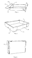
- Figs 2-6 Illustrated in Figs 2-6 are different stages in the forming of a container starting with the blank shown in Figure 1 .
- Strings of adhesive G are first applied to the flaps 13, which strings of adhesive are indicated in the Figures with heavy lines and are three in number in the example shown in Figure 2 . More or fewer strings of adhesive can naturally be applied.
- the short side parts 5 are then folded upwards about the creasing lines 3, after which the long side parts 4 are folded upwards about the creasing lines 2, and the adhesive-bearing flaps 13 are then folded inwards along the creasing lines 14 towards the underparts 7 of the upward-folded short side parts 5, as illustrated in Figure 3 , and are attached to these.
- the creasing lines 14 which demarcate the edges of the longitudinal sides are not parallel to the creasing lines 3, but are inclined at an angle ⁇ to a line parallel to the creasing line 3.
- the short side parts 5 will be inclined at an angle of 90° plus ⁇ to the bottom part 6 when the underparts 7 are attached to the inward-folded flaps 13, as illustrated in Figure 4 .
- the angle ⁇ is equivalent to three degrees.
- Strings of adhesive G are then applied to the outside of the flaps 13 and to the flaps 11 on the outer short side parts 8.
- adhesive can be applied to the outer short side parts 8 in those parts thereof which, after folding, come into contact with the flaps 13.
- the short side parts 5 are then folded about the creasing lines 9,10, so that the outer short side parts 8 come into contact with the flaps 13 that are attached to the inner short side parts 7, as illustrated in Figure 6 .
- the flaps 11 that are attached to the outer short side parts 8 are folded in towards the outside of the long side parts 4 and are attached to these.
- the finished container is shown in Figures 7 and 8 in perspective views respectively from above and from below.
- the outer short side parts 8 exhibit a smaller height than the inner short side parts 7, which means that the resulting container has an underpart that is situated vertically below the lower edges of the short side parts 7 and also below the lower edges of the flaps 11, which underpart has smaller external dimensions than the rest of the container.
- the outward inclination of the short side parts due to the angle ⁇ also contributes to the fact that the underpart has smaller dimensions than the upper part of the container.
- the long side parts 4 also exhibit a smaller height than the short side parts 7.
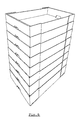
- the angle ⁇ and the difference in height between the outer and inner short side parts and between the long side parts and the inner short side parts are selected in such a way that the aforementioned underpart of the container fits into the uppermost part of a similar container, so that the containers can be stacked one on top of the other, as illustrated in Figure 9 .
- the difference in height between the outer and inner short side parts must be the same as or smaller than the difference in height between the long side parts and the inner short side parts in order for the load imposed by other containers stacked on top of a container to act essentially against the upper edge on the short sides of the container.
- the upper edges of the flaps 11 will also extend above the upper edges of the long side parts, which ensures the stability in the transverse direction of containers that are stacked on top of one another.
- the wall thickness is 3.75 ⁇ 0.5 mm.
- the total weight of the container was 350 g, whereas a plastic container with the same dimensions weighs 2 kg.
- the transport weight is also reduced, which naturally brings significant cost savings with it.
- the blank 1 also includes recesses which form openings for a user's hands in the finished container.
- a plastic container is preferably arranged at the bottom of the stack in order to absorb the shock loadings that can arise in conjunction with the careless handling of stacks of the kind that is encountered when the stacks are placed or set down on manually operated transport trucks.
- Containers in accordance with the invention can naturally be used for purposes other than the handling of packs of bread.
Landscapes
- Engineering & Computer Science (AREA)
- Mechanical Engineering (AREA)
- Cartons (AREA)
- Containers Having Bodies Formed In One Piece (AREA)
- Details Of Rigid Or Semi-Rigid Containers (AREA)
Abstract
Description
- The present invention relates to a container made of corrugated cardboard comprising a bottom and long sides and short sides projecting upwards from the bottom, in conjunction with which the short sides include two parts, an inner part and an outer part, folded towards one another, and a blank for manufacturing such a container.
- Bread rolls for hot dog sausages are baked centrally in large quantities and are packed in plastic bags, which are then laid in stackable containers or trays that are then distributed to storage facilities or individual shops. These bread trays are typically manufactured from plastic and can be transported in stacks of more than twenty filled trays stacked one on top of the other. One disadvantage associated with the use of plastic trays is that empty trays occupy a large space at the hot dog bread roll bakery and in the shops, and that empty trays from the shops must be transported back to the hot dog bread roll bakery to be refilled with packs of hot dog bread rolls. Another problem associated with such plastic trays is that they have a tendency to disappear from the distribution chain, with the result that not all empty trays find their way back to the hot dog bread roll bakery after having been delivered to the shops. This means that the stock of bread trays needs to be replenished from time to time.
-
SE-C2-508006 Claim 1.GB-A-2160507 FR 2263940 - The object of the present invention is to reduce these inconveniences by making available a container made of corrugated board, which is constructed in such a way that it can absorb the loads arising in stacks of filled containers and which is capable of being substituted fully or partially for such plastic trays.
- This object is achieved in accordance, with the invention through a container according to
claim 1. Such a container has an underpart situated beneath the bottom edge of the outer part of the short side, which can be introduced into a similar container or into a container made of plastic having the same dimensions. The container in accordance with the invention is thus able to replace plastic containers having the same dimensions in stacks of containers. The corrugated board container is stored before use in the form of a flat container blank, which takes up very little space. The container is also intended for disposable use, which means that an empty container does not need to be stored in the shop, but can be taken away as waste paper. A further advantage of the corrugated board container is that it is significantly lighter than a corresponding plastic container. - In a preferred embodiment, the outer part is demarcated from the inner part by means of an interjacent part defined by two parallel creasing lines, which are situated at a distance from one another that exceeds the combined thickness of the inner and outer short side parts. Flaps also extend executed in a single piece with the long sides between the inner and outer parts of the short sides over at least one part of the width of the short sides, and flaps executed in a single piece with the outer parts of the shorter sides extend over a part of the long sides on the outside of these. The inner and outer parts of the short sides are glued to the interjacent pieces of material executed in a single piece with the long sides, and the long sides are glued to the pieces of material executed in a single piece with the outer parts of the short sides.
- The invention also relates to a blank for manufacturing a container in accordance with claim 6.
- The invention also relates to the use of one or more corrugated board containers according to
claim 7. - The lowest container in such a stack of containers preferably consists of a plastic container.
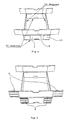
- The invention is now described with reference to the accompanying figures, in which:
-
Fig. 1 shows a plan view of a blank for manufacturing a container in accordance with a first preferred embodiment of the invention; -
Figs 2-6 show different stages in the manufacture of a container based on the blank inFig. 1 ; -
Figs 7 and 8 show a perspective view of a finished container viewed respectively from above and at an angle from below; -
Fig. 9 shows a perspective view of eight containers in accordance with the invention stacked in one another. - Shown in
Figure 1 is a plan view of a blank 1 made of corrugated cardboard to make available a container in accordance with a preferred embodiment of the invention. The blank 1 is stamped from a sheet of corrugated cardboard with the undulating lines in the undulating layer parallel to the longitudinal direction of the blank.Longitudinal creasing lines 2 andtransverse creasing lines 3 are also stamped in the corrugated cardboard blank in order to demarcate thebottom parts 4 of the blank, which constitute long sides of the finished container, and theparts 5 of the blank, which constitute short sides of the finished container, from the bottom part 6. Eachshort side part 5 comprises aninner part 7 adjacent to the bottom part 6 and anouter part 8, which are demarcated from one another via twoparallel creasing lines short side parts 8 are also extended in the transverse direction by means of twoflaps 11 that are demarcated from theshort side parts 8 viacreasing lines 12, and thelong side parts 4 are extended in the longitudinal direction by means of twoflaps 13 demarcated from the long sides viacreasing lines 14. Thecreasing lines Figure 1 , while thecreasing lines creasing lines - Illustrated in
Figs 2-6 are different stages in the forming of a container starting with the blank shown inFigure 1 . Strings of adhesive G are first applied to theflaps 13, which strings of adhesive are indicated in the Figures with heavy lines and are three in number in the example shown inFigure 2 . More or fewer strings of adhesive can naturally be applied. Theshort side parts 5 are then folded upwards about thecreasing lines 3, after which thelong side parts 4 are folded upwards about thecreasing lines 2, and the adhesive-bearingflaps 13 are then folded inwards along thecreasing lines 14 towards theunderparts 7 of the upward-foldedshort side parts 5, as illustrated inFigure 3 , and are attached to these. - As can be appreciated from
Figure 1 , thecreasing lines 14 which demarcate the edges of the longitudinal sides are not parallel to thecreasing lines 3, but are inclined at an angle α to a line parallel to thecreasing line 3. In this way, theshort side parts 5 will be inclined at an angle of 90° plus α to the bottom part 6 when theunderparts 7 are attached to the inward-foldedflaps 13, as illustrated inFigure 4 . In the illustrated example, the angle α is equivalent to three degrees. - Strings of adhesive G are then applied to the outside of the
flaps 13 and to theflaps 11 on the outershort side parts 8. Instead of applying adhesive to the outside of theflaps 13, as shown inFigure 5 , adhesive can be applied to the outershort side parts 8 in those parts thereof which, after folding, come into contact with theflaps 13. Theshort side parts 5 are then folded about thecreasing lines short side parts 8 come into contact with theflaps 13 that are attached to the innershort side parts 7, as illustrated inFigure 6 . Finally, theflaps 11 that are attached to the outershort side parts 8 are folded in towards the outside of thelong side parts 4 and are attached to these. - The finished container is shown in
Figures 7 and 8 in perspective views respectively from above and from below. As can be appreciated from these figures, the outershort side parts 8 exhibit a smaller height than the innershort side parts 7, which means that the resulting container has an underpart that is situated vertically below the lower edges of theshort side parts 7 and also below the lower edges of theflaps 11, which underpart has smaller external dimensions than the rest of the container. The outward inclination of the short side parts due to the angle α also contributes to the fact that the underpart has smaller dimensions than the upper part of the container. Thelong side parts 4 also exhibit a smaller height than theshort side parts 7. The angle α and the difference in height between the outer and inner short side parts and between the long side parts and the inner short side parts are selected in such a way that the aforementioned underpart of the container fits into the uppermost part of a similar container, so that the containers can be stacked one on top of the other, as illustrated inFigure 9 . In this case, the difference in height between the outer and inner short side parts must be the same as or smaller than the difference in height between the long side parts and the inner short side parts in order for the load imposed by other containers stacked on top of a container to act essentially against the upper edge on the short sides of the container. - As can be appreciated from the figures, the upper edges of the
flaps 11 will also extend above the upper edges of the long side parts, which ensures the stability in the transverse direction of containers that are stacked on top of one another. - The strength of a container in accordance with the invention has been tested by placing it in a plastic tray of similar dimensions, in conjunction with which filled trays were stacked on top of the container in accordance with the invention. In order to be able to replace existing plastic trays, it is necessary for the container to be capable of withstanding a load of 140 kg in such a test. A container in accordance with the invention with external dimensions of 600x395x110 mm manufactured from corrugated cardboard with the designation SCA 170 C sourced from SCA, Sweden, and with the use of an Instant-Pak 2300 hotmelt adhesive, was found to be capable of supporting more than 160 kg- SCA 170 C is constructed from outer liners with a weight per unit area of 186 g/cm2 and an interjacent semi chemical corrugated layer with a weight per unit area of 140 g/cm2. The wall thickness is 3.75 ± 0.5 mm. The total weight of the container was 350 g, whereas a plastic container with the same dimensions weighs 2 kg. In addition to improving the logistics by replacing plastic trays with containers in accordance with the invention, the transport weight is also reduced, which naturally brings significant cost savings with it.
- When the containers are stacked in one another in the manner illustrated in
Figure 9 , the load is absorbed essentially by the outershort side parts 8 and theflaps 13, which are in contact with the upper edge of the short sides of the container consisting of the material between thecreasing lines - As can be appreciated from the figures, the blank 1 also includes recesses which form openings for a user's hands in the finished container.
- When using the containers in accordance with the invention, a plastic container is preferably arranged at the bottom of the stack in order to absorb the shock loadings that can arise in conjunction with the careless handling of stacks of the kind that is encountered when the stacks are placed or set down on manually operated transport trucks.
- Containers in accordance with the invention can naturally be used for purposes other than the handling of packs of bread.
- The described embodiment can naturally be modified in a plurality of ways within the scope of the invention. For example, other dimensions and other qualities of corrugated cardboard can be used. The invention must accordingly be restricted only by the content of the accompanying patent claims.
Claims (7)
- A container made of corrugated cardboard comprising a bottom (6) and long sides (4) and short sides (5) projecting upwards from the bottom, in conjunction with which the short sides include two parts, an inner part (7) and an outer part (8), folded towards one another, the outer part (8) having a smaller height than the inner part (7) and that the long sides (4) having a smaller height than the short sides (5), characterized in that the short sides (5) being inclined at an angle of 90° plus α (α>0) to the bottom (6), the difference in height between the outer and inner short side parts being the same or smaller than the difference in height between the short and long sides.
- The container as claimed in claim 1, characterized
in that the outer part (8) is demarcated from the inner part by means of an interjacent part defined by two parallel creasing lines (9,10), which are situated at a distance from one another which exceeds the combined thickness of the inner and outer short side parts (7,8). - The container as claimed in claim 2, characterized
in that flaps (13), executed in a single piece with the long sides (4), extend between the inner (7) and outer (8) parts of the short sides over at least one part of the width of the short sides. - The container as claimed in claim 3, characterized
in that flaps (11), executed in a single piece with the outer parts (8) of the short sides, extend over a part of the long sides (4) on the outside of these. - The container as claimed in claim 4, characterized
in that the inner (7) and outer (8) parts of the short sides are glued to the Flaps (13), executed in a single piece with the long sides (4), and the long sides are glued to the Flaps (11) executed in a single piece with the outer parts (8) of the short sides. - A blank (1) for manufacturing a container according to claim 1 comprising a bottom (6), two long sides (4), two short sides (5) and flaps (11,13) projecting from the long sides and the short sides, in conjunction with which the short sides comprise an inner part (7) nearest the bottom and an outer part (8) at a distance from the bottom, as well as creasing lines (2,3,9,10,12,14), which demarcate the aforementioned parts from one another, the creasing lines (9,10), which demarcate the inner (7) and outer (8) parts of the short sides, are stamped from the opposite side from the creasing lines (2,3), which demarcate the bottom (6) from the long sides (4) and the short sides (5), the edges of the long sides (4) forming an angle of 90° plus α (α>0) to the creasing lines (2) democrating the long sides (4) from the bottom (6) and wherein the short and long sides (4,5) of the blank are so dimensioned that in erected state the long sides have a smaller height than the short sides, and the difference in height between the outer and inner short side parts being the same or smaller, than the difference in height between the short and long sides.
- The use of one or more corrugated cardboard containers according or claim 1 in a stack of similar corrugated cardboard containers and plastic containers with a similar form to the corrugated cardboard container.
Applications Claiming Priority (1)
| Application Number | Priority Date | Filing Date | Title |
|---|---|---|---|
| PCT/SE2005/000022 WO2006075935A1 (en) | 2005-01-11 | 2005-01-11 | A container made of corrugated cardboard, a blank and a use of the container |
Publications (2)
| Publication Number | Publication Date |
|---|---|
| EP1843947A1 EP1843947A1 (en) | 2007-10-17 |
| EP1843947B1 true EP1843947B1 (en) | 2008-12-17 |
Family
ID=36677906
Family Applications (1)
| Application Number | Title | Priority Date | Filing Date |
|---|---|---|---|
| EP05704696A Expired - Lifetime EP1843947B1 (en) | 2005-01-11 | 2005-01-11 | A container made of corrugated cardboard, a blank and a use of the container |
Country Status (5)
| Country | Link |
|---|---|
| EP (1) | EP1843947B1 (en) |
| AT (1) | ATE417788T1 (en) |
| DE (1) | DE602005011862D1 (en) |
| DK (1) | DK1843947T3 (en) |
| WO (1) | WO2006075935A1 (en) |
Families Citing this family (5)
| Publication number | Priority date | Publication date | Assignee | Title |
|---|---|---|---|---|
| FR2912728B1 (en) * | 2007-02-21 | 2011-04-08 | Smurfit Kappa France Sas | PRESENTATION TRAY. |
| WO2016054724A1 (en) * | 2014-10-07 | 2016-04-14 | Juma Maher | Merchandising, shipping and display container |
| CN107600619B (en) * | 2017-08-14 | 2024-03-19 | 北京赛升药业股份有限公司 | Medicine receiving box and use method thereof |
| KR200496512Y1 (en) | 2017-08-24 | 2023-02-14 | 스토라 엔소 오와이제이 | Leakproof and liquid-tight packaging box of corrugated board |
| JP2020189639A (en) * | 2019-05-20 | 2020-11-26 | レンゴー株式会社 | tray |
Family Cites Families (7)
| Publication number | Priority date | Publication date | Assignee | Title |
|---|---|---|---|---|
| GB899444A (en) * | 1960-07-15 | 1962-06-20 | Robert Skarstedt Aktiebolag | Improvements in packing cases |
| DK107926C (en) * | 1964-11-04 | 1967-07-17 | Brdr Schur Horsens As | Box of cardboard or similar material and with an inclined end wall. |
| FR2263940A1 (en) * | 1974-03-15 | 1975-10-10 | Barrez Ste Normande Carton Ond | Stackable corrugated cardboard fruit tray - has double thickness side walls and ventilation cut-outs |
| GB2160507A (en) * | 1984-06-22 | 1985-12-24 | Uk Corrugated Limited | Tray formed from a blank |
| CY1514A (en) * | 1985-02-21 | 1990-08-03 | Embalaje Iberoamericana | Stackable tray |
| DE9401380U1 (en) * | 1993-09-28 | 1994-03-31 | Haiss, Manfred, 71111 Waldenbuch | Cup-shaped packaging |
| SE508006C2 (en) * | 1995-04-04 | 1998-08-10 | Sca Packaging Sweden Ab | Reusable cardboard box assembly |
-
2005
- 2005-01-11 AT AT05704696T patent/ATE417788T1/en not_active IP Right Cessation
- 2005-01-11 DE DE602005011862T patent/DE602005011862D1/en not_active Expired - Fee Related
- 2005-01-11 EP EP05704696A patent/EP1843947B1/en not_active Expired - Lifetime
- 2005-01-11 DK DK05704696T patent/DK1843947T3/en active
- 2005-01-11 WO PCT/SE2005/000022 patent/WO2006075935A1/en not_active Ceased
Also Published As
| Publication number | Publication date |
|---|---|
| ATE417788T1 (en) | 2009-01-15 |
| DK1843947T3 (en) | 2009-04-14 |
| WO2006075935A1 (en) | 2006-07-20 |
| DE602005011862D1 (en) | 2009-01-29 |
| EP1843947A1 (en) | 2007-10-17 |
Similar Documents
| Publication | Publication Date | Title |
|---|---|---|
| JP5015401B2 (en) | Food and beverage carrier | |
| US20150336707A1 (en) | High strength partition box assembly | |
| AU2001273027A1 (en) | Beverage and food carrier | |
| US7159715B2 (en) | Container with integrated pallet for shipping television screens | |
| JPH09505792A (en) | Container with open top | |
| MX2012003592A (en) | Bakery tray. | |
| CA2565105C (en) | Platform comprising a blank and loading ledges | |
| CN100551789C (en) | Packaging systems for shipping multiple items | |
| US20110220520A1 (en) | Multi-purpose merchandise tray | |
| US5267663A (en) | Collapsible shipping container | |
| WO2006075935A1 (en) | A container made of corrugated cardboard, a blank and a use of the container | |
| US20030052038A1 (en) | Corrugated container with integral pallet | |
| AU596970B2 (en) | Packaging | |
| US20120305440A1 (en) | Layered product stacking structure | |
| JPH0326124Y2 (en) | ||
| CN216547211U (en) | Anti-falling high-strength corrugated carton | |
| IL29282A (en) | Container | |
| NZ547861A (en) | Nestable tray, blank, corresponding packaging and machine for forming one such tray | |
| JPH018515Y2 (en) | ||
| EP3626645A1 (en) | Cardboard palett | |
| NO164406B (en) | STABLE FOLD. | |
| US20120031898A1 (en) | Chafing dish transporter | |
| UA150728U (en) | Corrugated cardboard pallet | |
| CA2697286A1 (en) | Multipurpose merchandise tray | |
| US20110192809A1 (en) | Structure for the placement, display and packing of merchandise |
Legal Events
| Date | Code | Title | Description |
|---|---|---|---|
| PUAI | Public reference made under article 153(3) epc to a published international application that has entered the european phase |
Free format text: ORIGINAL CODE: 0009012 |
|
| 17P | Request for examination filed |
Effective date: 20070810 |
|
| AK | Designated contracting states |
Kind code of ref document: A1 Designated state(s): AT BE BG CH CY CZ DE DK EE ES FI FR GB GR HU IE IS IT LI LT LU MC NL PL PT RO SE SI SK TR |
|
| DAX | Request for extension of the european patent (deleted) | ||
| GRAP | Despatch of communication of intention to grant a patent |
Free format text: ORIGINAL CODE: EPIDOSNIGR1 |
|
| GRAS | Grant fee paid |
Free format text: ORIGINAL CODE: EPIDOSNIGR3 |
|
| GRAA | (expected) grant |
Free format text: ORIGINAL CODE: 0009210 |
|
| AK | Designated contracting states |
Kind code of ref document: B1 Designated state(s): AT BE BG CH CY CZ DE DK EE ES FI FR GB GR HU IE IS IT LI LT LU MC NL PL PT RO SE SI SK TR |
|
| REG | Reference to a national code |
Ref country code: GB Ref legal event code: FG4D |
|
| REG | Reference to a national code |
Ref country code: CH Ref legal event code: EP |
|
| REG | Reference to a national code |
Ref country code: IE Ref legal event code: FG4D |
|
| REF | Corresponds to: |
Ref document number: 602005011862 Country of ref document: DE Date of ref document: 20090129 Kind code of ref document: P |
|
| REG | Reference to a national code |
Ref country code: SE Ref legal event code: TRGR |
|
| REG | Reference to a national code |
Ref country code: DK Ref legal event code: T3 |
|
| PG25 | Lapsed in a contracting state [announced via postgrant information from national office to epo] |
Ref country code: LT Free format text: LAPSE BECAUSE OF FAILURE TO SUBMIT A TRANSLATION OF THE DESCRIPTION OR TO PAY THE FEE WITHIN THE PRESCRIBED TIME-LIMIT Effective date: 20081217 |
|
| PGFP | Annual fee paid to national office [announced via postgrant information from national office to epo] |
Ref country code: DK Payment date: 20090305 Year of fee payment: 5 |
|
| PG25 | Lapsed in a contracting state [announced via postgrant information from national office to epo] |
Ref country code: NL Free format text: LAPSE BECAUSE OF FAILURE TO SUBMIT A TRANSLATION OF THE DESCRIPTION OR TO PAY THE FEE WITHIN THE PRESCRIBED TIME-LIMIT Effective date: 20081217 Ref country code: PL Free format text: LAPSE BECAUSE OF FAILURE TO SUBMIT A TRANSLATION OF THE DESCRIPTION OR TO PAY THE FEE WITHIN THE PRESCRIBED TIME-LIMIT Effective date: 20081217 Ref country code: SI Free format text: LAPSE BECAUSE OF FAILURE TO SUBMIT A TRANSLATION OF THE DESCRIPTION OR TO PAY THE FEE WITHIN THE PRESCRIBED TIME-LIMIT Effective date: 20081217 Ref country code: FI Free format text: LAPSE BECAUSE OF FAILURE TO SUBMIT A TRANSLATION OF THE DESCRIPTION OR TO PAY THE FEE WITHIN THE PRESCRIBED TIME-LIMIT Effective date: 20081217 |
|
| PGFP | Annual fee paid to national office [announced via postgrant information from national office to epo] |
Ref country code: FI Payment date: 20090206 Year of fee payment: 5 |
|
| NLV1 | Nl: lapsed or annulled due to failure to fulfill the requirements of art. 29p and 29m of the patents act | ||
| PG25 | Lapsed in a contracting state [announced via postgrant information from national office to epo] |
Ref country code: BG Free format text: LAPSE BECAUSE OF FAILURE TO SUBMIT A TRANSLATION OF THE DESCRIPTION OR TO PAY THE FEE WITHIN THE PRESCRIBED TIME-LIMIT Effective date: 20090317 Ref country code: BE Free format text: LAPSE BECAUSE OF FAILURE TO SUBMIT A TRANSLATION OF THE DESCRIPTION OR TO PAY THE FEE WITHIN THE PRESCRIBED TIME-LIMIT Effective date: 20081217 Ref country code: EE Free format text: LAPSE BECAUSE OF FAILURE TO SUBMIT A TRANSLATION OF THE DESCRIPTION OR TO PAY THE FEE WITHIN THE PRESCRIBED TIME-LIMIT Effective date: 20081217 Ref country code: RO Free format text: LAPSE BECAUSE OF FAILURE TO SUBMIT A TRANSLATION OF THE DESCRIPTION OR TO PAY THE FEE WITHIN THE PRESCRIBED TIME-LIMIT Effective date: 20081217 Ref country code: ES Free format text: LAPSE BECAUSE OF FAILURE TO SUBMIT A TRANSLATION OF THE DESCRIPTION OR TO PAY THE FEE WITHIN THE PRESCRIBED TIME-LIMIT Effective date: 20090328 |
|
| PG25 | Lapsed in a contracting state [announced via postgrant information from national office to epo] |
Ref country code: IS Free format text: LAPSE BECAUSE OF FAILURE TO SUBMIT A TRANSLATION OF THE DESCRIPTION OR TO PAY THE FEE WITHIN THE PRESCRIBED TIME-LIMIT Effective date: 20090417 Ref country code: AT Free format text: LAPSE BECAUSE OF FAILURE TO SUBMIT A TRANSLATION OF THE DESCRIPTION OR TO PAY THE FEE WITHIN THE PRESCRIBED TIME-LIMIT Effective date: 20081217 Ref country code: CZ Free format text: LAPSE BECAUSE OF FAILURE TO SUBMIT A TRANSLATION OF THE DESCRIPTION OR TO PAY THE FEE WITHIN THE PRESCRIBED TIME-LIMIT Effective date: 20081217 Ref country code: PT Free format text: LAPSE BECAUSE OF FAILURE TO SUBMIT A TRANSLATION OF THE DESCRIPTION OR TO PAY THE FEE WITHIN THE PRESCRIBED TIME-LIMIT Effective date: 20090518 Ref country code: MC Free format text: LAPSE BECAUSE OF NON-PAYMENT OF DUE FEES Effective date: 20090131 |
|
| PGFP | Annual fee paid to national office [announced via postgrant information from national office to epo] |
Ref country code: SE Payment date: 20090204 Year of fee payment: 5 |
|
| REG | Reference to a national code |
Ref country code: CH Ref legal event code: PL |
|
| PG25 | Lapsed in a contracting state [announced via postgrant information from national office to epo] |
Ref country code: SK Free format text: LAPSE BECAUSE OF FAILURE TO SUBMIT A TRANSLATION OF THE DESCRIPTION OR TO PAY THE FEE WITHIN THE PRESCRIBED TIME-LIMIT Effective date: 20081217 |
|
| PLBE | No opposition filed within time limit |
Free format text: ORIGINAL CODE: 0009261 |
|
| STAA | Information on the status of an ep patent application or granted ep patent |
Free format text: STATUS: NO OPPOSITION FILED WITHIN TIME LIMIT |
|
| REG | Reference to a national code |
Ref country code: IE Ref legal event code: MM4A |
|
| PG25 | Lapsed in a contracting state [announced via postgrant information from national office to epo] |
Ref country code: CH Free format text: LAPSE BECAUSE OF NON-PAYMENT OF DUE FEES Effective date: 20090131 Ref country code: DE Free format text: LAPSE BECAUSE OF NON-PAYMENT OF DUE FEES Effective date: 20090801 Ref country code: LI Free format text: LAPSE BECAUSE OF NON-PAYMENT OF DUE FEES Effective date: 20090131 |
|
| 26N | No opposition filed |
Effective date: 20090918 |
|
| GBPC | Gb: european patent ceased through non-payment of renewal fee |
Effective date: 20090317 |
|
| REG | Reference to a national code |
Ref country code: FR Ref legal event code: ST Effective date: 20091030 |
|
| PG25 | Lapsed in a contracting state [announced via postgrant information from national office to epo] |
Ref country code: IE Free format text: LAPSE BECAUSE OF NON-PAYMENT OF DUE FEES Effective date: 20090111 |
|
| PG25 | Lapsed in a contracting state [announced via postgrant information from national office to epo] |
Ref country code: GB Free format text: LAPSE BECAUSE OF NON-PAYMENT OF DUE FEES Effective date: 20090317 Ref country code: FR Free format text: LAPSE BECAUSE OF NON-PAYMENT OF DUE FEES Effective date: 20090217 |
|
| REG | Reference to a national code |
Ref country code: DK Ref legal event code: EBP |
|
| EUG | Se: european patent has lapsed | ||
| PG25 | Lapsed in a contracting state [announced via postgrant information from national office to epo] |
Ref country code: GR Free format text: LAPSE BECAUSE OF FAILURE TO SUBMIT A TRANSLATION OF THE DESCRIPTION OR TO PAY THE FEE WITHIN THE PRESCRIBED TIME-LIMIT Effective date: 20090318 |
|
| PG25 | Lapsed in a contracting state [announced via postgrant information from national office to epo] |
Ref country code: DK Free format text: LAPSE BECAUSE OF NON-PAYMENT OF DUE FEES Effective date: 20100131 |
|
| PG25 | Lapsed in a contracting state [announced via postgrant information from national office to epo] |
Ref country code: IT Free format text: LAPSE BECAUSE OF FAILURE TO SUBMIT A TRANSLATION OF THE DESCRIPTION OR TO PAY THE FEE WITHIN THE PRESCRIBED TIME-LIMIT Effective date: 20081217 |
|
| PG25 | Lapsed in a contracting state [announced via postgrant information from national office to epo] |
Ref country code: LU Free format text: LAPSE BECAUSE OF NON-PAYMENT OF DUE FEES Effective date: 20090111 |
|
| PG25 | Lapsed in a contracting state [announced via postgrant information from national office to epo] |
Ref country code: HU Free format text: LAPSE BECAUSE OF FAILURE TO SUBMIT A TRANSLATION OF THE DESCRIPTION OR TO PAY THE FEE WITHIN THE PRESCRIBED TIME-LIMIT Effective date: 20090618 |
|
| PG25 | Lapsed in a contracting state [announced via postgrant information from national office to epo] |
Ref country code: TR Free format text: LAPSE BECAUSE OF FAILURE TO SUBMIT A TRANSLATION OF THE DESCRIPTION OR TO PAY THE FEE WITHIN THE PRESCRIBED TIME-LIMIT Effective date: 20081217 |
|
| PG25 | Lapsed in a contracting state [announced via postgrant information from national office to epo] |
Ref country code: CY Free format text: LAPSE BECAUSE OF FAILURE TO SUBMIT A TRANSLATION OF THE DESCRIPTION OR TO PAY THE FEE WITHIN THE PRESCRIBED TIME-LIMIT Effective date: 20081217 |
|
| PG25 | Lapsed in a contracting state [announced via postgrant information from national office to epo] |
Ref country code: SE Free format text: LAPSE BECAUSE OF NON-PAYMENT OF DUE FEES Effective date: 20100112 |