EP1843481A1 - Generalized two-stage data estimation - Google Patents
Generalized two-stage data estimation Download PDFInfo
- Publication number
- EP1843481A1 EP1843481A1 EP07112889A EP07112889A EP1843481A1 EP 1843481 A1 EP1843481 A1 EP 1843481A1 EP 07112889 A EP07112889 A EP 07112889A EP 07112889 A EP07112889 A EP 07112889A EP 1843481 A1 EP1843481 A1 EP 1843481A1
- Authority
- EP
- European Patent Office
- Prior art keywords
- matrix
- code
- diagonal matrix
- received
- block diagonal
- Prior art date
- Legal status (The legal status is an assumption and is not a legal conclusion. Google has not performed a legal analysis and makes no representation as to the accuracy of the status listed.)
- Withdrawn
Links
Images


Classifications
-
- H—ELECTRICITY
- H04—ELECTRIC COMMUNICATION TECHNIQUE
- H04B—TRANSMISSION
- H04B1/00—Details of transmission systems, not covered by a single one of groups H04B3/00 - H04B13/00; Details of transmission systems not characterised by the medium used for transmission
- H04B1/69—Spread spectrum techniques
- H04B1/707—Spread spectrum techniques using direct sequence modulation
- H04B1/7097—Interference-related aspects
- H04B1/7103—Interference-related aspects the interference being multiple access interference
- H04B1/7105—Joint detection techniques, e.g. linear detectors
- H04B1/71052—Joint detection techniques, e.g. linear detectors using decorrelation matrix
-
- H—ELECTRICITY
- H04—ELECTRIC COMMUNICATION TECHNIQUE
- H04B—TRANSMISSION
- H04B2201/00—Indexing scheme relating to details of transmission systems not covered by a single group of H04B3/00 - H04B13/00
- H04B2201/69—Orthogonal indexing scheme relating to spread spectrum techniques in general
- H04B2201/707—Orthogonal indexing scheme relating to spread spectrum techniques in general relating to direct sequence modulation
- H04B2201/70707—Efficiency-related aspects
Definitions
- the present invention relates to wireless communication systems. More particularly, the present invention is directed to data estimation in such systems.
- JD joint detection
- ISI intersymbol interference
- MAI multiple-access interference
- JD is characterized by good performance but high complexity. Even using approximate Cholesky or block Fourier transforms with Cholesky decomposition algorithms, the complexity of JD is still very high.
- JD is adopted in a wireless receiver, its complexity prevents the receiver from being implemented efficiently. This evidences the need for alternative algorithms that are not only simple in implementation but also good in performance.
- Symbols are to be recovered from signals received in a shared spectrum. Codes of the signals received in the shared spectrum are processed using a block Fourier transform (FT), producing a code block diagonal matrix. A channel response of the received signals is estimated. The channel response is extended and modified to produce a block circulant matrix and a block FT is taken, producing a channel response block diagonal matrix. The code block diagonal matrix is combined with the channel response block diagonal matrix. The received signals are sampled and processed using the combined code block diagonal matrix and the channel response block diagonal matrix with a Cholesky algorithm. A block inverse FT is performed on a result of the Cholesky algorithm to produce spread symbols. The spread symbols are despread to recover symbols of the received signals.
- FT block Fourier transform
- Figure 1 is a block diagram showing a two stage data detection.
- Figure 2 is a block diagram of an embodiment of two-stage data detection.
- Figure 3 is a block diagram of code assignment to reduce the complexity of two-stage data detection.
- Figures 4A-4D are block diagrams of utilizing look-up tables to determine ⁇ R .
- a two stage data estimator can be used in a wireless transmit/receive unit (WTRU) or base station, when all of the communications to be detected by the estimator experience a similar channel response.
- WTRU wireless transmit/receive unit
- W-CDMA wideband code division multiple access
- FIG. 1 is a simplified block diagram of a receiver using a two stage data estimator 55.
- An antenna 50 or antenna array receives radio frequency signals.
- the signals are sampled by a sampling device 51, typically at the chip rate or at a multiple of the chip rate, producing a received vector r .
- a channel estimation device 53 using a reference signal, such as a midamble sequence or pilot code, estimates the channel response for the received signals as a channel response matrix H.
- the channel estimation device 53 also estimates the noise variance, ⁇ 2 .
- the channel equalizer 52 takes the received vector r and equalizes it using the channel response matrix H and the noise variance ( ⁇ 2 , producing a spread symbol vector s .
- a despreader 54 despreads the spread symbol vector s , producing the estimated symbols d .
- the dimensions and structures of the above vectors and matrixes depend on specific system design. Usually, different systems have different system parameters such as frame structure, length of data field and length of delay spread.
- the matrix A has the different values of dimensions for different systems and the dimensions of matrix A depend on the length of data field, number of codes, spreading factor and length of delay spread.
- the matrix A has dimensions of 1032 by 488 for a WCDMA TDD system if burst type 1 is used and for delay spread of 57 chips long, while matrix A has dimensions of 367 by 176 for TD-SCDMA system for a delay spread of 16 chips long.
- the received signal can be viewed as a composite signal, denoted by s , passed through a single channel.
- W is the length of the channel response, and is therefore equal to the length of the delay spread.
- Q, K and N s denote the spread factor (SF), the number of active codes and the number of symbols carried on each channelization code, respectively.
- c i k is the i th element of the k th code.
- the matrix C is a matrix of size N s ⁇ Q by N s ⁇ K
- Equation (9) can be expressed in two stages:
- the first stage is the stage of generalized channel equalization. It estimates the spread signal s by an equalization process per Equation 10.
- the second stage is the despreading stage.
- the symbol sequence d is recovered by a despreading process per Equation 11.
- the block R 0 in the diagonal is a square matrix of size Q .
- the matrix R c is a square matrix of size N s ⁇ Q.
- the matrix R c is a block circular matrix
- the block Fast Fourier transform (FFT) can be used to realize the algorithm.
- the block circular matrix can be decomposed into simple and efficient FFT components, making a matrix inverse more efficient and less complex.
- the large matrix inverse is more efficient when it is performed in the frequency domain rather than in a time domain.
- it is advantage to use FFT and the use of a block circular matrix enables efficient FFT implementation.
- L is the number of data symbols affected by the delay spread of propagation channel is expressed as:
- H can be extended and modified into an exactly block circular matrix of the form:
- H C H 0 H L - 1 H 2 H 1 H 1 H 0 H L - 1 H 2 H 2 H 1 H L - 1 H L - 1 H 2 H L - 1 O H 0 H 1 H 0 H 2 H 1 H 0 H L - 1 H 2 H 1 H 0 H L - 1 H 2 H 1 H 0
- the block circular matrix H c is obtained by expanding the columns of matrix H in Equation (17) by circularly down-shifting one element block successively.
- H C F Q - 1 ⁇ ⁇ H ⁇ F Q
- H c (:,1:Q) denotes the first Q columns of matrix H c .
- Equation 10 ⁇ is obtained:
- Equations (23) and (24) can be performed using Cholesky decomposition and forward and backward substitutions.
- ⁇ H is a diagonal matrix whose diagonal is F ⁇ H(:,1) in which H(:,1) denotes the first column of matrix H.
- the notation (.)* denotes conjugate operator.
- Figure 2 is a preferred block diagram of the channel equalizer 15.
- a code matrix C is input into the channel equalizer 15.
- a Hermitian device 30 takes a complex conjugate transpose of the code matrix C, C H .
- the code matrix C and its Hermitian are multiplied by a multiplier 32, producing CC H .
- a block FT performed on CC H . producing block diagonal matrix ⁇ R .
- the channel response matrix H is extended and modified by an extend and modify device 36, producing H C .
- a block FT 38 takes H c and produces block diagonal matrix ⁇ H .
- a multiplier 40 multiplies ⁇ H and ⁇ R together, producing ⁇ H ⁇ R .
- a Hermitian device 42 takes the complex conjugate transpose of ⁇ H , producing ⁇ H H .
- a multiplier 44 multiplies ⁇ H H to ⁇ H , ⁇ R , producing ⁇ H ⁇ ⁇ R ⁇ H H , and an adder 46 adds to ⁇ 2 I , producing ⁇ H ⁇ ⁇ R ⁇ ⁇ H H + ⁇ 2 ⁇ I .
- a Cholesky decomposition device 48 produces a Cholesky factor.
- a block FT 20 takes a block FT of the received vector r .
- forward and backward substitution are performed by a forward substitution device 22 and backward substitution device 24.
- a conjugation device 56 takes the conjugate of ⁇ H , producing ⁇ . H .
- the result of backward substitution is multiplied at multiplier 58 to ⁇ H .
- a block inverse FT 60 takes a block inverse FT of the multiplied result, producing ⁇ .
- an approximate solution in which the generalized two-stage data detection process is a block-diagonal-approximation.
- the block-diagonal-approximation includes off-diagonal entries as well as the diagonal entries in the approximation process.
- R o a combination of four channelization codes, comprises a constant block diagonal part, which does not vary with the different combinations of the codes, and an edge part which changes with the combinations.
- R o has the structure of:
- the elements designated as x represent some variables whose values and locations vary with different combinations of channelization codes. Their locations vary following certain patterns depending on combinations of codes. As a result only a few of them are non-zero.
- code power is considered and is not unity power, the element c equals the total power of transmitted codes.
- a good approximation of the matrix R o is to include the constant part and ignore the variable part as:
- R ⁇ 0 contains only a constant part.
- R ⁇ 0 depends only on the number of active codes regardless of which codes are transmitted, and R ⁇ C can be decomposed as shown is Equation (13).
- the block diagonal of ⁇ R or F (Q) R ⁇ C (:,1: Q ) can be pre-calculated using an FFT for different numbers of codes and stored as a look-up table. This reduces the computational complexity by not computing F ( Q ) R C (:,1: Q ).
- the matrix R ⁇ 0 can be expressed as
- a scaling P avg should be applied in the process.
- block-diagonal approximation method can be derived by including more entries other than the constant block-diagonal part. This improves performance but entails more complexity because by including variable entries the FFT for F (Q) R c (:,1 : Q) has to be now recalculated as needed if the codes change. The use of more entries enhances the exact solution as all of the off-diagonal entries are included for processing.
- the assignment of channelization codes or resource units can be made following the rules that a code set is randomly picked among the code sets that have common constant part and those codes in the picked code set are assigned. For example of assignment of four codes, the code sets [1,2,3,4], [5,6,7,8], [9,10,11,12], .... have the common constant part in their correlation matrix. When channel assignment of four codes is made, one of those code sets should be used for optimal computational efficiency.
- Figure 3 is a flow diagram of such a channel code assignment. Codes sets having a constant part are determined, step 100. When assigning codes, the code sets having the constant part are used, step 102.
- Figures 4A, 4B, 4C and 4D are illustrations of preferred circuits for reducing the complexity in calculating ⁇ R .
- the number of codes processed by the two stage data detector are put in a look-up table 62 and the ⁇ R associated with that code number is used.
- the number of codes processed by the two stage data detector are put in a look-up table 64 and an unscaled ⁇ R is produced.
- the unscaled ⁇ R is scaled, such as by a multiplier 66 by P avg , producing ⁇ R .
- the code matrix C or code identifier is input into a look-up table 68.
- the ⁇ R is determined.
- the unscaled ⁇ R is scaled, such as by a multiplier 72 by P avg , producing ⁇ R .
- the code matrix C or code identifier is input into a look-up table 70, producing an unscaled ⁇ R .
Landscapes
- Physics & Mathematics (AREA)
- Mathematical Physics (AREA)
- Engineering & Computer Science (AREA)
- Computer Networks & Wireless Communication (AREA)
- Signal Processing (AREA)
- Mobile Radio Communication Systems (AREA)
Abstract
Description
- FIELD OF INVENTION
- The present invention relates to wireless communication systems. More particularly, the present invention is directed to data estimation in such systems.
- BACKGROUND
- In wireless systems, joint detection (JD) is used to mitigate intersymbol interference (ISI) and multiple-access interference (MAI). JD is characterized by good performance but high complexity. Even using approximate Cholesky or block Fourier transforms with Cholesky decomposition algorithms, the complexity of JD is still very high. When JD is adopted in a wireless receiver, its complexity prevents the receiver from being implemented efficiently. This evidences the need for alternative algorithms that are not only simple in implementation but also good in performance.
- To overcome this problem, prior art receivers based on a channel equalizer followed by a code despreader have been developed. These types of receivers are called single user detection (SUD) receivers because, contrary to JD receivers, the detection process does not require the knowledge of channelization codes of other users. SUD tends to not exhibit the same performance as JD for most data rates of interest, even though its complexity is very low. Accordingly, there exists a need for low complexity high performance data detectors.
- SUMMARY
- Symbols are to be recovered from signals received in a shared spectrum. Codes of the signals received in the shared spectrum are processed using a block Fourier transform (FT), producing a code block diagonal matrix. A channel response of the received signals is estimated. The channel response is extended and modified to produce a block circulant matrix and a block FT is taken, producing a channel response block diagonal matrix. The code block diagonal matrix is combined with the channel response block diagonal matrix. The received signals are sampled and processed using the combined code block diagonal matrix and the channel response block diagonal matrix with a Cholesky algorithm. A block inverse FT is performed on a result of the Cholesky algorithm to produce spread symbols. The spread symbols are despread to recover symbols of the received signals.
- BRIEF DESCRIPTION OF THE DRAWINGS
- Figure 1 is a block diagram showing a two stage data detection.
- Figure 2 is a block diagram of an embodiment of two-stage data detection.
- Figure 3 is a block diagram of code assignment to reduce the complexity of two-stage data detection.
- Figures 4A-4D are block diagrams of utilizing look-up tables to determine Λ R.
- DETAILED DESCRIPTION OF THE PREFERRED EMBODIMENT(S)
- The present invention will be described with reference to the drawing figures where like numerals represent like elements throughout.
- A two stage data estimator can be used in a wireless transmit/receive unit (WTRU) or base station, when all of the communications to be detected by the estimator experience a similar channel response. Although the following is described in conjunction with the preferred proposed third generation partnership project (3GPP) wideband code division multiple access (W-CDMA) communication system, it is applicable to other systems.
- Figure 1 is a simplified block diagram of a receiver using a two
stage data estimator 55. Anantenna 50 or antenna array receives radio frequency signals. The signals are sampled by asampling device 51, typically at the chip rate or at a multiple of the chip rate, producing a received vector r . Achannel estimation device 53 using a reference signal, such as a midamble sequence or pilot code, estimates the channel response for the received signals as a channel response matrix H. Thechannel estimation device 53 also estimates the noise variance, σ2. - The
channel equalizer 52 takes the received vector r and equalizes it using the channel response matrix H and the noise variance (σ2 , producing a spread symbol vector s . Using codes C of the received signals, adespreader 54 despreads the spread symbol vector s , producing the estimated symbols d . - With joint detection (JD), a minimum mean square error (MMSE) formula with respect to the symbol vector d can be expressed as:


- The matrix A has the different values of dimensions for different systems and the dimensions of matrix A depend on the length of data field, number of codes, spreading factor and length of delay spread. By way of example, for the transmission of 8 codes with spreading factor 16 each, the matrix A has dimensions of 1032 by 488 for a WCDMA TDD system if
burst type 1 is used and for delay spread of 57 chips long, while matrix A has dimensions of 367 by 176 for TD-SCDMA system for a delay spread of 16 chips long. - Assuming white noise and uncorrelated symbols with unity energy, Rn = σ2I and Rd = I, where I denotes the identity matrix. Substitution of these into
Equations 1 and 2 results in:

- The received signal can be viewed as a composite signal, denoted by s , passed through a single channel. The received signalr may be represented by r = Hs , where H is the channel response matrix and s is the composite spread signal. H takes the form of:

- In Equation (5), W is the length of the channel response, and is therefore equal to the length of the delay spread. Typically W=57 for W-CDMA time division duplex (TDD)
burst type 1 and W=16 for time division synchronous CDMA (TD-SCDMA). The composite spread signal s can be expressed ass = Cd , where the symbol vector d is:


- Q, K and Ns denote the spread factor (SF), the number of active codes and the number of symbols carried on each channelization code, respectively.

- Substitution of A = HC into Equation (4) results in:
-

- Rc = CCH . If ŝ denotes the estimated spread signal, Equation (9) can be expressed in two stages:
- Stage 1:

- Stage 2:

- The first stage is the stage of generalized channel equalization. It estimates the spread signal s by an equalization process per Equation 10. The second stage is the despreading stage. The symbol sequence d is recovered by a despreading process per Equation 11.
- The matrix Rc in Equation 9 is a block diagonal matrix of the form:

- The block R 0 in the diagonal is a square matrix of size Q. The matrix Rc is a square matrix of size Ns ·Q.
- Because the matrix Rc is a block circular matrix, the block Fast Fourier transform (FFT) can be used to realize the algorithm. With this approach the matrix Rc can be decomposed as:


- FNs is the Ns -point FFT matrix, IQ is the identity matrix of size Q and the notation ⊗ is the Kronecker product. By definition, the Kronecker product Z of matrix X and Y, (Z = X ⊗ Y) is:

F(Q)Rc(:,l: Q). That is,
- The block circular matrix can be decomposed into simple and efficient FFT components, making a matrix inverse more efficient and less complex. Usually, the large matrix inverse is more efficient when it is performed in the frequency domain rather than in a time domain. For this reason, it is advantage to use FFT and the use of a block circular matrix enables efficient FFT implementation. With proper partition, the matrix H can be expressed as an approximate block circular matrix of the form:

where each Hi, i =0,1,...,L-1 is a square matrix of size Q. L is the number of data symbols affected by the delay spread of propagation channel is expressed as: -

- To enable block FFT decomposition, H can be extended and modified into an exactly block circular matrix of the form:
-

- The block circular matrix Hc is obtained by expanding the columns of matrix H in Equation (17) by circularly down-shifting one element block successively.
- The matrix Hc can be decomposed by block FFT as:

- Λ H is a block-diagonal matrix whose diagonal blocks are F (Q) Hc (:,1:Q), as

- Hc(:,1:Q) denotes the first Q columns of matrix Hc . From Equation (20),


-

- For a zero forcing (ZF) solution, equation 19 is simplified to

- The matrix inverse in Equations (23) and (24) can be performed using Cholesky decomposition and forward and backward substitutions.
- In a special case of K=SF, where (the number of active codes equals the spreading factor), the matrix RC becomes a scalar-diagonal matrix with identical diagonal elements equal to SF. In this case, Equations (10) and (11) reduce to:


- Equation (25) can also be expressed in the form of:
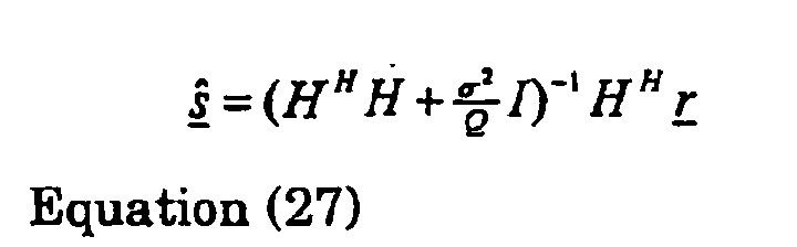
- With FFT, Equations (25) and (27) can be realized by:


- Figure 2 is a preferred block diagram of the
channel equalizer 15. A code matrix C is input into thechannel equalizer 15. AHermitian device 30 takes a complex conjugate transpose of the code matrix C, CH. The code matrix C and its Hermitian are multiplied by amultiplier 32, producing CCH. A block FT performed on CCH. producing block diagonal matrix ΛR. - The channel response matrix H is extended and modified by an extend and modify
device 36, producing HC . Ablock FT 38 takes Hc and produces block diagonal matrix Λ H. Amultiplier 40 multiplies Λ H and Λ R together, producing Λ H Λ R . AHermitian device 42 takes the complex conjugate transpose of Λ H , producing
multiplier 44 multiplies

adder 46 adds to σ 2I , producing
- A
Cholesky decomposition device 48 produces a Cholesky factor. Ablock FT 20 takes a block FT of the received vector r . Using the Cholesky factor and the FT of r, forward and backward substitution are performed by aforward substitution device 22 andbackward substitution device 24. - A
conjugation device 56 takes the conjugate of Λ H , producing Λ. H . The result of backward substitution is multiplied atmultiplier 58 to Λ·H . A blockinverse FT 60 takes a block inverse FT of the multiplied result, producing ŝ . - According to another embodiment of the present invention, an approximate solution is provided in which the generalized two-stage data detection process is a block-diagonal-approximation. The block-diagonal-approximation includes off-diagonal entries as well as the diagonal entries in the approximation process.
- As an example, the case of four channelization codes is considered. Ro, a combination of four channelization codes, comprises a constant block diagonal part, which does not vary with the different combinations of the codes, and an edge part which changes with the combinations. In general Ro has the structure of:
-

- where elements denoted as c represent constants and are always equal to the number of channelization codes, i.e., c = K . The elements designated as x represent some variables whose values and locations vary with different combinations of channelization codes. Their locations vary following certain patterns depending on combinations of codes. As a result only a few of them are non-zero. When code power is considered and is not unity power, the element c equals the total power of transmitted codes. A good approximation of the matrix Ro is to include the constant part and ignore the variable part as:
-

- In this case, the approximation R̂ 0 contains only a constant part. R̂ 0 depends only on the number of active codes regardless of which codes are transmitted, and R̂C can be decomposed as shown is Equation (13). The block diagonal of Λ R or F(Q)R̂C (:,1:Q) can be pre-calculated using an FFT for different numbers of codes and stored as a look-up table. This reduces the computational complexity by not computing F(Q)RC (:,1:Q). In the case, that code power is considered and is not unity power, the element c becomes total power of active codes, (i.e., c=PT in which PT is the total power of active codes). The matrix R̂ 0 can be expressed as
-

- where Pavg is the average code power obtained by

- Other variants of block-diagonal approximation method can be derived by including more entries other than the constant block-diagonal part. This improves performance but entails more complexity because by including variable entries the FFT for F(Q)Rc (:,1 : Q) has to be now recalculated as needed if the codes change. The use of more entries enhances the exact solution as all of the off-diagonal entries are included for processing.
- At a given number of channelization codes, one can derive the code sets for different combinations of channelization codes that have common constant part of the correlation matrix whose values are equal to the number of channelization codes, or the total power of channelization codes when the code does not have unity code power. To facilitate the low complexity implementation, the assignment of channelization codes or resource units can be made following the rules that a code set is randomly picked among the code sets that have common constant part and those codes in the picked code set are assigned. For example of assignment of four codes, the code sets [1,2,3,4], [5,6,7,8], [9,10,11,12], .... have the common constant part in their correlation matrix. When channel assignment of four codes is made, one of those code sets should be used for optimal computational efficiency.
- Figure 3 is a flow diagram of such a channel code assignment. Codes sets having a constant part are determined,
step 100. When assigning codes, the code sets having the constant part are used,step 102. - Figures 4A, 4B, 4C and 4D are illustrations of preferred circuits for reducing the complexity in calculating Δ R . In Figure 4A, the number of codes processed by the two stage data detector are put in a look-up table 62 and the ΛR associated with that code number is used. In Figure 4B, the number of codes processed by the two stage data detector are put in a look-up table 64 and an unscaled ΛR is produced. The unscaled ΛR is scaled, such as by a
multiplier 66 by P avg , producing Λ R . - In Figure 4C, the code matrix C or code identifier is input into a look-up table 68. Using the look-up table 68, the ΛR is determined. The unscaled ΛR is scaled, such as by a
multiplier 72 by P avg, producing Λ R . In Figure 4D, the code matrix C or code identifier is input into a look-up table 70, producing an unscaled Λ R . -
- 1. A method for recovering symbols from signals received in a shared spectrum, the method comprising:
- processing codes of the signals received in the shared spectrum using a block Fourier transform (FT) and producing a code block diagonal matrix;
- estimating a channel response of the received signals;
- extending and modifying the channel response to produce a block circulant matrix and taking a block FT and producing a channel response block diagonal matrix;
- combining the code block diagonal matrix and the channel response block diagonal matrix;
- sampling the received signals;
- processing the received signal using the combined code block diagonal matrix and the channel response block diagonal matrix with a Cholesky algorithm;
- performing a block inverse FT on a result of the Cholesky algorithm to produce spread symbols; and
- despreading the spread symbols to recover symbols of the received signals.
- 2. The method of
item 1 wherein the Cholesky algorithm includes determining a Cholesky factor and performing forward and backward substitution. - 3. The method of
item 1 wherein the combining the code block diagonal matrix and the channel response block diagonal matrix includes adding factor of the noise variance multiplied with an identity matrix. - 4. The method of
item 1 wherein the code block diagonal matrix is produced by multiplying a code matrix with a complex conjugate transpose of the code matrix and taking a block FT of a result of the multiplying. - 5. The method of
item 1 wherein the code block diagonal matrix is produced by inputting a number of codes of interest into a look-up table. - 6. The method of
item 1 wherein the code block diagonal matrix is produced by inputting a number of codes of interest into a look-up table and scaling a resulting diagonal block matrix from the look-up table by an average power level. - 7. The method of
item 1 wherein the code block diagonal matrix is produced by inputting code identifiers of the received signals into a look-up table. - 8. The method of
item 1 wherein the code block diagonal matrix is produced by inputting code identifiers of the received signals into a look-up table and scaling a resulting diagonal block matrix from the look-up table by an average power level. - 9. The method of
item 1 wherein the code block diagonal matrix is produced by inputting codes of the received signal into a look-up table. - 10. The method of
item 1 wherein the code block diagonal matrix is produced by inputting inputing codes of the received signal into a look-up table and scaling a resulting diagonal block matrix from the look-up table by an average power level. - 11. A wireless transmit/receive unit (WTRU) for use in recovering symbols from signals received in a shared spectrum, the WTRU comprising:
- means for processing codes of the signals received in the shared spectrum using a block Fourier transform (FT) and producing a code block diagonal matrix;
- means for estimating a channel response of the received signals;
- means for extending and modifying the channel response to produce a block circulant matrix and taking a block FT and producing a channel response block diagonal matrix;
- means for combining the code block diagonal matrix and the channel response block diagonal matrix;
- means for sampling the received signals;
- means for processing the received signal using the combined code block diagonal matrix and the channel response block diagonal matrix with a Cholesky algorithm;
- means for performing a block inverse FT on a result of the Cholesky algorithm to produce spread symbols; and
- means for despreading the spread symbols to recover symbols of the received signals.
- 12. The WTRU of item 11 wherein the Cholesky algorithm includes determining a Cholesky factor and performing forward and backward substitution.
- 13. The WTRU of item 11 wherein the combining the code block diagonal matrix and the channel response block diagonal matrix includes adding factor of the noise variance multiplied with an identity matrix.
- 14. The WTRU of item 11 wherein the code block diagonal matrix is produced by multiplying a code matrix with a complex conjugate transpose of the code matrix and taking a block FT of a result of the multiplying.
- 15. The WTRU of item 11 wherein the code block diagonal matrix is produced by inputting a number of codes of interest into a look-up table.
- 16. The WTRU of item 11 wherein the code block diagonal matrix is produced by inputting a number of codes of interest into a look-up table and scaling a resulting diagonal block matrix from the look-up table by an average power level.
- 17. The WTRU of item 11 wherein the code block diagonal matrix is produced by inputting code identifiers of the received signals into a look-up table.
- 18. The WTRU of item 11 wherein the code block diagonal matrix is produced by inputting code identifiers of the received signals into a look-up table and scaling a resulting diagonal block matrix from the look-up table by an average power level.
- 19. The WTRU of item 11 wherein the code block diagonal matrix is produced by inputting codes of the received signal into a look-up table.
- 20. The WTRU of item 11 wherein the code block diagonal matrix is produced by inputting inputing codes of the received signal into a look-up table and scaling a resulting diagonal block matrix from the look-up table by an average power level.
- 31. A wireless transmit/receive unit (WTRU) for use in recovering symbols from signals received in a shared spectrum, the WTRU comprising:
- a block Fourier transform (FT) device for processing codes of the signals received in the shared spectrum using a block FT and producing a code block diagonal matrix;
- a channel estimation device for estimating a channel response of the received signals;
- an extending and modifying block for extending and modifying the channel response to produce a block circulant matrix and taking a block FT and producing a channel response block diagonal matrix;
- a circuit for combining the code block diagonal matrix and the channel response block diagonal matrix;
- a sampling device for sampling the received signals;
- a Cholesky decomposition device and forward and backward substitution devices for processing the received signal using the combined code block diagonal matrix and the channel response block diagonal matrix with a Cholesky algorithm;
- an inverse block FT device for performing a block inverse FT on an output of the backward substitution device to produce spread symbols; and
- a despreader for despreading the spread symbols to recover symbols of the received signals.
- 32. The WTRU of item 31 wherein the circuit for combining comprises a two multipliers.
- 33. The WTRU of item 31 wherein the circuit for combining includes adding factor of the noise variance multiplied with an identity matrix.
- 34. The WTRU of item 31 further comprising a Hermitian device and a multiplier for multiplying a code matrix with a complex conjugate transpose of the code matrix.
- 35. The WTRU of item 31 further comprising a look-up table wherein the code block diagonal matrix is produced by inputting a number of codes of interest into a look-up table.
- 36. The WTRU of item 31 comprising a look-up table and a multiplier wherein the code block diagonal matrix is produced by inputting a number of codes of interest into a look-up table and multiplying a resulting diagonal block matrix from the look-up table by an average power level.
- 37. The WTRU of item 31 further comprising a look-up table wherein the code block diagonal matrix is produced by inputting code identifiers of the received signals into a look-up table.
- 38. The WTRU of item 31 comprising a look-up table and a multiplier wherein the code block diagonal matrix is produced by inputting code identifiers of the received signals into a look-up table and multiplying a resulting diagonal block matrix from the look-up table by an average power level.
- 39. The WTRU of item 31 further comprising a look-up table wherein the code block diagonal matrix is produced by inputting codes of the received signal into a look-up table.
- 40. The WTRU of item 31 comprising a look-up table and a multiplier wherein the code block diagonal matrix is produced by inputting inputting codes of the received signal into a look-up table and multiplying a resulting diagonal block matrix from the look-up table by an average power level.
- 51. A base station for use in recovering symbols from signals received in a shared spectrum, the base station comprising:
- means for processing codes of the signals received in the shared spectrum using a block Fourier transform (FT) and producing a code block diagonal matrix;
- means for estimating a channel response of the received signals;
- means for extending and modifying the channel response to produce a block circulant matrix and taking a block FT and producing a channel response block diagonal matrix;
- means for combining the code block diagonal matrix and the channel response block diagonal matrix;
- means for sampling the received signals;
- means for processing the received signal using the combined code block diagonal matrix and the channel response block diagonal matrix with a Cholesky algorithm;
- means for performing a block inverse FT on a result of the Cholesky algorithm to produce spread symbols; and
- means for despreading the spread symbols to recover symbols of the received signals.
- 52. The base station of
item 51 wherein the Cholesky algorithm includes determining a Cholesky factor and performing forward and backward substitution. - 53. The base station of
item 51 wherein the combining the code block diagonal matrix and the channel response block diagonal matrix includes adding factor of the noise variance multiplied with an identity matrix. - 54. The base station of
item 51 wherein the code block diagonal matrix is produced by multiplying a code matrix with a complex conjugate transpose of the code matrix and taking a block FT of a result of the multiplying. - 55. The base station of
item 51 wherein the code block diagonal matrix is produced by inputting a number of codes of interest into a look-up table. - 56. The base station of
item 51 wherein the code block diagonal matrix is produced by inputting a number of codes of interest into a look-up table and scaling a resulting diagonal block matrix from the look-up table by an average power level. - 57. The base station of
item 51 wherein the code block diagonal matrix is produced by inputting code identifiers of the received signals into a look-up table. - 58. The base station of
item 51 wherein the code block diagonal matrix is produced by inputting code identifiers of the received signals into a look-up table and scaling a resulting diagonal block matrix from the look-up table by an average power level. - 59. The base station of
item 51 wherein the code block diagonal matrix is produced by inputting codes of the received signal into a look-up table. - 60. The base station of
item 51 wherein the code block diagonal matrix is produced by inputting inputting codes of the received signal into a look-up table and scaling a resulting diagonal block matrix from the look-up table by an average power level. - 61. A base station for use in recovering symbols from signals received in a shared spectrum, the base station comprising:
- a block Fourier transform (FT) device for processing codes of the signals received in the shared spectrum using a block FT and producing a code block diagonal matrix;
- a channel estimation device for estimating a channel response of the received signals;
- an extending and modifying block for extending and modifying the channel response to produce a block circulant matrix and taking a block FT and producing a channel response block diagonal matrix;
- a circuit for combining the code block diagonal matrix and the channel response block diagonal matrix;
- a sampling device for sampling the received signals;
- a Cholesky decomposition device and forward and backward substitution devices for processing the received signal using the combined code block diagonal matrix and the channel response block diagonal matrix with a Cholesky algorithm;
- an inverse block FT device for performing a block inverse FT on an output of the backward substitution device to produce spread symbols; and
- a despreader for despreading the spread symbols to recover symbols of the received signals.
- 62. The base station of item 61 wherein the circuit for combining comprises a two multipliers.
- 63. The base station of item 61 wherein the circuit for combining includes adding factor of the noise variance multiplied with an identity matrix.
- 64. The base station of item 61 further comprising a Hermitian device and a multiplier for multiplying a code matrix with a complex conjugate transpose of the code matrix.
- 65. The base station of item 61 further comprising a look-up table wherein the code block diagonal matrix is produced by inputting a number of codes of interest into a look-up table.
- 66. The base station of item 61 comprising a look-up table and a multiplier wherein the code block diagonal matrix is produced by inputting a number of codes of interest into a look-up table and multiplying a resulting diagonal block matrix from the look-up table by an average power level.
- 67. The base station of item 61 further comprising a look-up table wherein the code block diagonal matrix is produced by inputting code identifiers of the received signals into a look-up table.
- 68. The base station of item 61 comprising a look-up table and a multiplier wherein the code block diagonal matrix is produced by inputting code identifiers of the received signals into a look-up table and multiplying a resulting diagonal block matrix from the look-up table by an average power level.
- 69. The base station of item 61 further comprising a look-up table wherein the code block diagonal matrix is produced by inputting codes of the received signal into a look-up table.
- 70. The base station of item 61 comprising a look-up table and a multiplier wherein the code block diagonal matrix is produced by inputting inputting codes of the received signal into a look-up table and multiplying a resulting diagonal block matrix from the look-up table by an average power level.
Claims (13)
- A wireless transmit/receive unit (WTRU) configured to receive (50) and sample (51) wireless signals in a shared spectrum where the wireless signals comprise encoded symbols, the WTRU characterized by:a channel estimation device (53) configured to process received signal samples to produce an estimate of a channel response of the received signals corresponding to a matrix H;said channel estimation device (53) further configured to process the received signal samples to produce an estimate of noise variance σ2 of the received signals;
a two stage data estimator (55) comprising a first stage channel equalizer (52) and a second stage despreader (54);
said channel equalizer (52) configured to process received signal samples using the estimated channel response matrix H and the estimate of noise variance σ2 to produce a spread signal estimate of the received signals; and
said despreader (54) configured to process the spread signal estimate of the received signals produced by said channel equalizer to recover encoded symbols of the received signals. - The WTRU of claim 1 wherein said channel equalizer (52) includes:means (34) for processing codes of the signals received in a shared spectrum using a block Fourier transform (FT) and producing a code block diagonal matrix;means (36, 38) for extending and modifying the channel response matrix H to produce a channel response block diagonal matrix;means (40, 42, 44, 46) for combining the code block diagonal matrix and the channel response block diagonal matrix;means (48, 20, 22, 24, 58) for processing the received signal samples using the combined code block diagonal matrix and the channel response block diagonal matrix with the noise variance σ2 and a Cholesky algorithm; andmeans (60) for performing a block inverse FT on a result of the Cholesky algorithm to produce the spread signal estimate of the received signals.
- The WTRU of claim 2 wherein said means (48, 20, 22, 24, 58) for processing the received signal samples using the combined code block diagonal matrix and the channel response block diagonal matrix with the noise variance σ2 and a Cholesky algorithm includes means (46) for adding a factor of the noise variance multiplied with an identity matrix.
- The WTRU of claim 2 or 3 wherein said means (34) for processing codes of the signals received in a shared spectrum using a block Fourier transform (FT) and producing a code block diagonal matrix includes a Hermitian device (30) and a multiplier (32) for multiplying a code matrix with a complex conjugate transpose of the code matrix.
- The WTRU of claim 1, 2, 3 or 4 wherein said channel equalizer (52) includes a look-up table wherein the code block diagonal matrix is produced by inputting a number of codes of interest, code identifiers of the received signals or codes of the received signal into the look-up table.
- The WTRU of claim 1, 2, 3 or 4 wherein said channel equalizer (52) includes a look-up table and a multiplier wherein the code block diagonal matrix is produced by inputting a number of codes of interest, code identifiers of the received signals or codes of the received signal into the look-up table and multiplying a resulting diagonal block matrix from the look-up table by an average power level.
- The WTRU of claim 1, 2, 3, 4, 5, 6 or 7 configured as a base station.
- A method for a wireless transmit/receive unit (WTRU) that receives and samples wireless signals in a shared spectrum where the wireless signals comprise encoded symbols, the method characterized by:processing received signal samples to produce an estimate of a channel response of the received signals corresponding to a matrix H;processing the received signal samples to produce an estimate of noise variance σ 2of the received signals;using a two stage data estimator (55) comprising a first stage channel equalizer (52) and a second stage despreader (54);using said channel equalizer (52) to process received signal samples using the estimated channel response matrix H and the estimate of noise variance σ 2 to produce a spread signal estimate of the received signals; andusing said despreader (54) to process the spread signal estimate of the received signals produced by said channel equalizer to recover encoded symbols of the received signals.
- The method of claim 8 wherein using said channel equalizer (52) includes:processing codes of the signals received in a shared spectrum using a block Fourier transform (FT) and producing a code block diagonal matrix;extending and modifying the channel response matrix H to produce a channel response block diagonal matrix;combining the code block diagonal matrix and the channel response block diagonal matrix;processing the received signal samples using the combined code block diagonal matrix and the channel response block diagonal matrix with the noise variance σ 2 and a Cholesky algorithm; andperforming a block inverse FT on a result of the Cholesky algorithm to produce the spread signal estimate of the received signals.
- The method of claim 9 wherein the processing of the received signal samples using the combined code block diagonal matrix and the channel response block diagonal matrix with the noise variance σ2 and a Cholesky algorithm includes adding a factor of the noise variance multiplied with an identity matrix.
- The method of claim 9 or 10 wherein the processing of codes of the signals received in a shared spectrum using a block Fourier transform (FT) and producing of a code block diagonal matrix includes multiplying a code matrix with a complex conjugate transpose of the code matrix.
- The method of claim 8, 9, 10 or 11 where said channel equalizer (52) includes a look-up table wherein the code block diagonal matrix is produced by inputting a number of codes of interest, code identifiers of the received signals or codes of the received signal into the look-up table.
- The method of claim 8, 9, 10 or 11 where said channel equalizer (52) includes a look-up table and a multiplier wherein the code block diagonal matrix is produced by inputting a number of codes of interest, code identifiers of the received signals or codes of the received signal into the look-up table and multiplying a resulting diagonal block matrix from the look-up table by an average power level.
Applications Claiming Priority (2)
| Application Number | Priority Date | Filing Date | Title |
|---|---|---|---|
| US43928403P | 2003-01-10 | 2003-01-10 | |
| EP04700894A EP1582008B1 (en) | 2003-01-10 | 2004-01-08 | Generalized two-stage data estimation |
Related Parent Applications (1)
| Application Number | Title | Priority Date | Filing Date |
|---|---|---|---|
| EP04700894A Division EP1582008B1 (en) | 2003-01-10 | 2004-01-08 | Generalized two-stage data estimation |
Publications (1)
| Publication Number | Publication Date |
|---|---|
| EP1843481A1 true EP1843481A1 (en) | 2007-10-10 |
Family
ID=38462185
Family Applications (1)
| Application Number | Title | Priority Date | Filing Date |
|---|---|---|---|
| EP07112889A Withdrawn EP1843481A1 (en) | 2003-01-10 | 2004-01-08 | Generalized two-stage data estimation |
Country Status (1)
| Country | Link |
|---|---|
| EP (1) | EP1843481A1 (en) |
Citations (2)
| Publication number | Priority date | Publication date | Assignee | Title |
|---|---|---|---|---|
| WO2002063779A2 (en) | 2001-02-06 | 2002-08-15 | Interdigital Technology Corporation | Low complexity data detection using fast fourier transform of channel correlation matrix |
| WO2002089346A1 (en) | 2001-04-30 | 2002-11-07 | Interdigital Technology Corporation | Fast joint detection |
-
2004
- 2004-01-08 EP EP07112889A patent/EP1843481A1/en not_active Withdrawn
Patent Citations (2)
| Publication number | Priority date | Publication date | Assignee | Title |
|---|---|---|---|---|
| WO2002063779A2 (en) | 2001-02-06 | 2002-08-15 | Interdigital Technology Corporation | Low complexity data detection using fast fourier transform of channel correlation matrix |
| WO2002089346A1 (en) | 2001-04-30 | 2002-11-07 | Interdigital Technology Corporation | Fast joint detection |
Similar Documents
| Publication | Publication Date | Title |
|---|---|---|
| EP1582008B1 (en) | Generalized two-stage data estimation | |
| EP1222746B9 (en) | Receiver for multiuser detection of cdma signals | |
| EP1391048B1 (en) | Fast joint detection | |
| EP1686696B1 (en) | Single user detection | |
| US7539238B2 (en) | Extended algorithm data estimator | |
| CN100542080C (en) | Combined detection method and device and system using the device | |
| US8295329B2 (en) | Efficient computation of soft scaling factors for linear multi-user detector |
Legal Events
| Date | Code | Title | Description |
|---|---|---|---|
| PUAI | Public reference made under article 153(3) epc to a published international application that has entered the european phase |
Free format text: ORIGINAL CODE: 0009012 |
|
| 17P | Request for examination filed |
Effective date: 20070720 |
|
| AC | Divisional application: reference to earlier application |
Ref document number: 1582008 Country of ref document: EP Kind code of ref document: P |
|
| AK | Designated contracting states |
Kind code of ref document: A1 Designated state(s): AT BE BG CH CY CZ DE DK EE ES FI FR GB GR HU IE IT LI LU MC NL PT RO SE SI SK TR |
|
| 17Q | First examination report despatched |
Effective date: 20080506 |
|
| AKX | Designation fees paid |
Designated state(s): AT BE BG CH CY CZ DE DK EE ES FI FR GB GR HU IE IT LI LU MC NL PT RO SE SI SK TR |
|
| RAP1 | Party data changed (applicant data changed or rights of an application transferred) |
Owner name: INTERDIGITAL TECHNOLOGY CORPORATION |
|
| STAA | Information on the status of an ep patent application or granted ep patent |
Free format text: STATUS: THE APPLICATION IS DEEMED TO BE WITHDRAWN |
|
| 18D | Application deemed to be withdrawn |
Effective date: 20150801 |