EP1843462A1 - Controller for brushless motor - Google Patents
Controller for brushless motor Download PDFInfo
- Publication number
- EP1843462A1 EP1843462A1 EP07005184A EP07005184A EP1843462A1 EP 1843462 A1 EP1843462 A1 EP 1843462A1 EP 07005184 A EP07005184 A EP 07005184A EP 07005184 A EP07005184 A EP 07005184A EP 1843462 A1 EP1843462 A1 EP 1843462A1
- Authority
- EP
- European Patent Office
- Prior art keywords
- axis
- value
- current
- calculation
- target voltage
- Prior art date
- Legal status (The legal status is an assumption and is not a legal conclusion. Google has not performed a legal analysis and makes no representation as to the accuracy of the status listed.)
- Granted
Links
- 238000004804 winding Methods 0.000 claims abstract description 51
- 230000004907 flux Effects 0.000 claims abstract description 10
- 230000007423 decrease Effects 0.000 claims description 20
- 238000001514 detection method Methods 0.000 claims description 16
- 230000003247 decreasing effect Effects 0.000 description 14
- 238000010586 diagram Methods 0.000 description 14
- 230000004043 responsiveness Effects 0.000 description 12
- 238000000034 method Methods 0.000 description 9
- 230000000052 comparative effect Effects 0.000 description 7
- 230000004044 response Effects 0.000 description 6
- 238000006243 chemical reaction Methods 0.000 description 5
- 230000007246 mechanism Effects 0.000 description 2
- 230000002159 abnormal effect Effects 0.000 description 1
- 230000008859 change Effects 0.000 description 1
- 230000004048 modification Effects 0.000 description 1
- 238000012986 modification Methods 0.000 description 1
- 230000008569 process Effects 0.000 description 1
- 230000001105 regulatory effect Effects 0.000 description 1
Images






Classifications
-
- H—ELECTRICITY
- H02—GENERATION; CONVERSION OR DISTRIBUTION OF ELECTRIC POWER
- H02P—CONTROL OR REGULATION OF ELECTRIC MOTORS, ELECTRIC GENERATORS OR DYNAMO-ELECTRIC CONVERTERS; CONTROLLING TRANSFORMERS, REACTORS OR CHOKE COILS
- H02P21/00—Arrangements or methods for the control of electric machines by vector control, e.g. by control of field orientation
- H02P21/06—Rotor flux based control involving the use of rotor position or rotor speed sensors
Definitions
- the present invention relates to a controller for a brushless motor that determines differences between target currents and detected currents in a dq coordinate system and determines a target voltage applied to an armature winding based on a feedback calculation, such as PI (Proportional Integral) calculation, P (Proportional) calculation, or PID (Proportional Integral Derivative) calculation, to decrease the differences.
- PI Proportional Integral
- P Proportional
- PID Proportional Integral Derivative
- a conventional controller for a brushless motor comprises a current detection part that detects currents flowing in the armature winding, a rotation position detection part that detects a rotation position of a rotor of the motor, a dq-axes target current calculation part that calculates a d-axis target current and a q-axis target current, a dq-axes current calculation part that determines a d-axis current and a q-axis current based on the detected currents and the detected rotation position, a d-axis target voltage calculation part that determines a d-axis target voltage based on the PI calculation for the d-axis current so as to decrease a d-axis difference between the d-axis target current and the d-axis current, and a q-axis target voltage calculation part that determines a q-axis target voltage based on the PI calculation for the q-axis current so as to decrease a q-axis difference between the q
- limiters for limiting the target voltages are required to prevent the target voltage applied to the armature winding from exceeding a maximum set value, with preventing the waveform representing the variation of voltage applied to the armature winding relative to the variation of the rotation position of the rotor from being discontinuous. If the limiters are not provided, the results of the PI calculation continuously increase in a case where the differences between the target currents and the detected currents are not decreased. As a result, a certain time is required for the target voltages corresponding to the results of the PI calculation to reach appropriate values even when the differences decrease.
- the waveform representing the variation of voltage applied to the armature winding relative to the variation of the rotation position of the rotor becomes discontinuous when the target voltages becomes too high.
- the waveform assumes a shape obtained by clipping the vicinity of peaks of the sine wave, thereby causing abnormal noise or vibrations.
- a d-axis difference ⁇ I d between a d-axis target current I d * and a d-axis current I d is determined in a d-axis PI calculation part 101a
- a result V do of the PI calculation is determined by performing the PI calculation
- a q-axis difference ⁇ I q between a q-axis target current I q * and a q-axis current I q is determined in a q-axis PI calculation part 101b
- a result V qo of the PI calculation is determined by performing the PI calculation.
- a d-axis limiting value and a q-axis limiting value are determined such that the target voltage applied to the armature winding does not exceed a set maximum value and a waveform representing the variation of the voltage applied to the armature winding relative to the variation of the rotation position of the rotor do not become discontinuous.
- a d-axis target voltage V d * is determined by limiting the absolute value of the result V do of the PI calculation for the d-axis current with a d-axis limiter 103 so that the absolute value becomes equal to or less than the d-axis limiting value
- a q-axis target voltage V q * is determined by limiting the absolute value of the result V qo of the PI calculation for the q-axis current with a q-axis limiter 104 so that the absolute value becomes equal to or less than the q-axis limiting value.
- the output value of the d-axis limiter 103 is used as a preceding value of the PI calculation for the d-axis current in the next calculation cycle
- the output value of the q-limiter 104 is used as a preceding value of the PI calculation for the q-axis current in the next calculation cycle.
- K P is a proportional gain
- K I is an integral gain
- Z -1 is a preceding value of signal.
- the responsiveness of the brushless motor fluctuates according to the rotation speed and current value even if the above-described limiters are provided, therefore stable responsiveness cannot be obtained. It is an object of the present invention to provide a controller for a brushless motor that can resolve such a problem.
- a controller for a brushless motor to which the present invention is applied comprises a current detection part that detect a current flowing in an armature winding of the brushless motor, a rotation position detection part that detects a rotation position of a rotor of the motor, a dq-axes target current calculation part that calculates a d-axis target current and a q-axis target current, where an axis along a magnetic flux direction of a field system of the rotor is taken as the d axis and an axis perpendicular to the d axis and a rotation axis of the rotor is taken as the q axis, a dq-axes current calculation part that determines a d-axis current and a q-axis current based on the detected current and the detected rotation position, a d-axis target voltage calculation part that determines a d-axis target voltage based on a feedback calculation for the d-axis current so as to decrease a
- the first feature of the present invention is that a d-axis correction value calculation part for determining a d-axis correction value - ⁇ L q I q and a q-axis correction value calculation part for determining a q-axis correction value ⁇ L d I d + ⁇ are provided, the d-axis target voltage is determined based on a value obtained by correcting a result of the feedback calculation for the d-axis current with the d-axis correction value - ⁇ L q I q , and the q-axis target voltage is determined based on a value obtained by correcting a result of the feedback calculation for the q-axis current with the q-axis correction value ⁇ L d I d + ⁇ .
- the second feature of the present invention is that a d-axis correction value calculation part for determining a d-axis correction value - ⁇ L q I q and a q-axis correction value calculation part for determining a q-axis correction value ⁇ L d I d , are provided, the d-axis target voltage is determined based on a value obtained by correcting a result of the feedback calculation for the d-axis current with the d-axis correction value - ⁇ L q I q , and the q-axis target voltage is determined based on a value obtained by correcting a result of the feedback calculation for the q-axis current with the q-axis correction value ⁇ L d I d .
- ⁇ stands for a rotation speed (rad/sec) of the rotor
- L d stands for a d-axis self-inductance of the armature winding
- Lq stands for a q-axis self-inductance of the armature winding
- I d stands for the d-axis current
- I q stands for the q-axis current
- ⁇ stands for a value obtained by multiplying a maximum value of magnetic flux linkage of the armature winding in the field system by a factor of (3/2) 1/2 .
- V d R + PL d ⁇ I d - ⁇ ⁇ L q ⁇ I q
- V q R + PL q ⁇ I q + ⁇ ⁇ L d ⁇ I d + ⁇
- the first feature of the present invention makes it possible to determine the q-axis target voltage based on the value obtained by correcting the result of the feedback calculation for the q-axis current with the q-axis correction value ⁇ L d I d + ⁇ , so that the influence on the responsiveness of the brushless motor due to the difference between the q-axis target voltage and the q-axis voltage arising in accordance with the rotation speed ⁇ , the d-axis current I d , and the magnetic flux ⁇ can be reduced by comparison with the case where no such correction is made.
- Using the second feature of the present invention makes it possible to determine the q-axis target voltage based on the value obtained by correcting the result of the feedback calculation for the q-axis current with the q-axis correction value ⁇ L d I d , so that the influence on the responsiveness of the brushless motor due to the difference between the q-axis target voltage and the q-axis voltage arising in accordance with the rotation speed ⁇ and the d-axis current I d can be reduced by comparison with the case where no such correction is made.
- the responsiveness of the brushless motor can be prevented from fluctuating even if the rotation speed and/or the current value change.
- the d-axis target voltage cannot be determined correctly when the result of the PI calculation for the d-axis current is corrected with the d-axis correction value, if the d-axis limiting value is determined without respect to the d-axis correction value and the result of the PI calculation for the d-axis current is limited with a single d-axis limiter.
- the correction value is added to the value used as the preceding value of the PI calculation in the next calculation cycle, so that there is a problem that the PI calculation cannot be performed appropriately.
- a case may be considered in which the result of the PI calculation for the d-axis current that is not corrected is used as the preceding value of the PI calculation for the d-axis current in the next calculation cycle (for example, in this case, the d-axis correction value is added to the result of the PI calculation for the d-axis current at the point of ⁇ in FIG.
- the preceding value of the PI calculation in the next calculation cycle cannot be limited by the d-axis limiter 103, so that there is a problem that the result of the PI calculation continues to increase when the difference between the target current and the detected current does not decrease.
- the absolute value of the result of the PI calculation for the d-axis current that is not corrected is limited to the d-axis limiting value by a single d-axis limiter (for example, in this case, the d-axis correction value is added to the result of the PI calculation for the d-axis current at the point of ⁇ in FIG. 11).
- the positive or negative of the d-axis correction value is set to decrease the absolute value of the d-axis target voltage
- the absolute value of the d-axis target voltage is further decreased by the correction after being decreased by the d-axis limiter 103.
- the absolute value of the d-axis target voltage is unnecessarily decreased, so that there is a problem that the power source voltage cannot be used effectively.
- the same problem arises when the result of the PI calculation for the q-axis current is corrected with the q-axis correction value.
- the above-described controller preferably comprises a dq-axes limiting value calculation part that determines a d-axis limiting value and a q-axis limiting value so that a target voltage applied to the armature winding does not exceed a set maximum value, a d-axis addition part that adds the d-axis correction value to the result of the feedback calculation for the d-axis current, a q-axis addition part that adds the q-axis correction value to the result of the feedback calculation for the q-axis current, a first d-axis limiter that limits an absolute value the sum of the d-axis correction value and the result of the feedback calculation for the d-axis current to the d-axis limiting value, a second d-axis limiter that limits an absolute value of the result of the feedback calculation for the d-axis current to the d-axis limiting value, a first q-axis limiter that limits an
- the absolute value of the sum of the d-axis correction value and the result of the feedback calculation for the d-axis current is limited to the d-axis limiting value by the first d-axis limiter.
- the d-axis target voltage can be determined based on the value limited by the first d-axis limiter, that is, the output value of the first d-axis limiter.
- the absolute value of the result of the feedback calculation for the d-axis current is limited to the d-axis limiting value by the second d-axis limiter.
- the value limited by the second d-axis limiter that is, the output value of the second d-axis limiter, can be used as a preceding value of the feedback calculation for the d-axis current in the next calculation cycle. Therefore, the result of the feedback calculation for the d-axis current can be corrected and the preceding value of the feedback calculation in the next calculation cycle can be limited to the d-axis limiting value, without unnecessarily decreasing the absolute value of the d-axis target value and without adding the correction value to the preceding value of the feedback calculation in the next calculation cycle.
- the absolute value of the sum of the q-axis correction value and the result of the feedback calculation for the q-axis current is limited to the q-axis limiting value by the first q-axis limiter.
- the q-axis target voltage can be determined based on the value limited to the first q-axis limiter, that is, the output value of the first q-axis limiter.
- the absolute value of the result of the feedback calculation for the q-axis current is limited to the q-axis limiting value by the second q-axis limiter.
- the value limited by the second q-axis limiter that is, the output value of the second q-axis limiter, can be used as a preceding value of the feedback calculation for the q-axis current in the next calculation cycle. Therefore, the result of feedback calculation for the q-axis current can be corrected and the preceding value of the feedback calculation in the next calculation cycle can be limited to the q-axis limiting value, without unnecessarily decreasing the absolute value of the q-axis target value and without adding the correction value to the preceding value of the feedback calculation in the next calculation cycle.
- the above-described controller preferably comprises a dq-axes limiting value calculation part that determines a d-axis limiting value and a q-axis limiting value so that a target voltage applied to the armature winding does not exceed a set maximum value, a d-axis corrected limiting value calculation part that determines a d-axis corrected limiting value that is obtained by subtracting an absolute value of the d-axis correction value from the d-axis limiting value, a q-axis corrected limiting value calculation part that determines a q-axis corrected limiting value that is obtained by subtracting an absolute value of the q-axis correction value from the q-axis limiting value, a d-axis limiter that limits an absolute value of the result of the feedback calculation for the d-axis current to the d-axis corrected limiting value, a q-axis limiter that limits an absolute value of the result of the feedback calculation for the q
- the d-axis corrected limiting value that is obtained by subtracting the absolute value of the d-axis correction value from the d-axis limiting value is determined by the d-axis corrected limiting value calculation part, and the absolute value of the result of the feedback calculation for the d-axis current is limited to the d-axis corrected limiting value by the d-axis limiter.
- the value limited by the d-axis limiter that is, the output value of the d-axis limiter, can be used as a preceding value of the feedback calculation for the d-axis current in the next calculation cycle.
- the d-axis target voltage can be determined based on the value obtained by adding the d-axis correction value to the output value of the d-axis limiter, that is, based on the output value of the d-axis addition part. Therefore, the result of the feedback calculation for the d-axis current can be corrected and the preceding value of the feedback calculation for the d-axis current in the next calculation cycle can be limited by the d-axis limiter, without unnecessarily decreasing the absolute value of the d-axis target voltage and without adding the correction value to the preceding value of the feedback calculation for the d-axis current in the next calculation cycle.
- the preceding value of the feedback calculation for the d-axis current in the next calculation cycle is limited to the d-axis corrected limiting value rather than to the d-axis limiting value.
- This d-axis limiting value is determined such that it does not exceed the set maximum value of the target voltage applied to the armature winding. Further, when one of the d-axis voltage and the q-axis voltage increases, the other decreases, and the d-axis correction value correlates with the q-axis current. Therefore, the d-axis corrected limiting value obtained by subtracting the absolute value of the d-axis correction value from the d-axis limiting value can be brought close to the actual maximum value that can be applied to the armature winding.
- the preceding value of the feedback calculation for the d-axis current in the next calculation cycle is prevented from being limited to an unnecessarily large limiting value, and the convergence ability of the result of the feedback calculation in the d-axis can be improved.
- the q-axis corrected limiting value that is obtained by subtracting the absolute value of the q-axis correction value from the q-axis limiting value is determined by the q-axis corrected limiting value calculation part, and the absolute value of the result of the feedback calculation for the q-axis current is limited to the q-axis corrected limiting value by the q-axis limiter.
- the value limited by the q-axis limiter that is, the output value of the q-axis limiter, can be used as the preceding value of the feedback calculation for the q-axis current in the next calculation cycle.
- the q-axis target voltage can be determined based on the value obtained by adding the q-axis correction value to the result of the feedback calculation for the q-axis current limited by the q-axis limiter with the q-axis addition part, that is, based on the output value of the q-axis addition part. Therefore, the result of the feedback calculation for the q-axis current can be corrected and the preceding value of the feedback calculation for the q-axis current in the next calculation cycle can be limited by the q-axis limiter, without unnecessarily decreasing the absolute value of the q-axis target voltage and without adding the correction value to the preceding value of the feedback calculation for the q-axis current in the next calculation cycle.
- the preceding value of the feedback calculation for the q-axis current in the next calculation cycle is limited to the q-axis corrected limiting value rather than to the q-axis limiting value.
- the q-axis limiting value is determined such that it does not exceed the set maximum value of the target voltage applied to the armature winding. Further, when one of the d-axis voltage and the q-axis voltage increases, the other decreases, and the q-axis correction value correlates with the d-axis current. Therefore, the q-axis corrected limiting value obtained by subtracting the absolute value of the q-axis correction value from the q-axis limiting value can be brought close to the actual maximum value that can be applied to the armature winding.
- the preceding value of the feedback calculation for the q-axis current in the next calculation cycle is prevented from being limited to an unnecessarily large limiting value, and the convergence ability of the result of the feedback calculation in the q-axis can be improved.
- the responsiveness of the brushless motor can be stabilized with eliminating the influence of the rotation speed and/or the current value.
- a controller for brushless motor of the first embodiment of the present invention is described below with reference to FIGS. 1 to 8B.
- An electric power steering device 101 of a rack-pinion type for a vehicle that is shown in FIG. 1 comprises a steering shaft 103 that is rotated by steering operation, a pinion 103a provided on the steering shaft 103, a rack 104 engaged with the pinion 103a, a three-phase brushless motor 1 for generating steering assist power, and a screw mechanism 110 for transmitting the output of the motor 1 to the rack 104.
- Each end of the rack 104 is linked to a wheel (no shown in the figures).
- the motor 1 comprises a stator 1a that is fixed to a housing 108 covering the rack 104, a cylindrical rotor 1b that is rotatably supported by the housing 108 via bearings 108a, 108b, and a magnet 1c provided as a field system of the rotor 1b.
- the stator 1a has three-phase coils constituting an armature winding of the motor 1. In the present embodiment, a U-phase coil, a V-phase coil, and a W-phase coil are provided as the three-phase coils.
- the rotor 1b surrounds the rack 104.
- a resolver 2 serves as a rotation position detection part that detects the rotation position of the rotor 1b.
- the screw mechanism 110 has a ball screw shaft 110a integrally formed on the outer periphery of the rack 104 and a ball nut 110b engaged with the ball screw shaft 110a via balls.
- the ball nut 110b is connected to the rotor 1b.
- the motor 1 rotates the ball nut 110b, the steering assist power is provided along the longitudinal direction of the rack 104.
- the motor 1 is connected to a controller 10.
- FIG. 2 A block diagram of FIG. 2 shows the configuration of the controller 10.
- the controller 10 has a current detection part 11, a signal processing part 12, and a drive part 13.
- the resolver 2, a torque sensor 7 that detects the steering torque transmitted by the steering shaft 103, and a vehicle velocity sensor 8 that detects the vehicle velocity are connected to the controller 10.
- the current detection part 11 detects currents flowing in the armature winding of the motor 1.
- the current detection part 11 of the present embodiment has current detectors 11u, 11v, 11w that detect respective phase currents in the three-phase coils and AD converters 11u', 11v', 11w' that perform AD conversion of current detection signals produced by the current detectors 11u, 11v, 11w.
- the signal processing part 12 is comprised, for example, of a microcomputer and has a basic target current calculation part 15, a dq-axes target current calculation part 16, a dq-axes current calculation part 17, a d-axes difference calculation part 18d, a q-axis difference calculation part 18q, a dq-axes target voltage calculation part 19, a target voltage coordinate conversion part 20, and PWM (pulse width modulation) control parts 21u, 21v, 21w.
- PWM pulse width modulation
- the drive part 13 has a pair of U-phase FET13u1, FET13u2, a pair of V-phase FET13v1, FET13v2, and a pair of W-phase FET13w1, FET13w2 as switching elements for power supply to constitute an inverter circuit.
- a point between the pair of FETs is connected to the coil of the motor 1 via a power supply line.
- the phase currents flowing between the drive part 13 and the coils of the motor 1 are detected by the current detectors 11u, 11v, 11w.
- the basic target current calculation part 15 calculates a basic target current I* of the motor 1 based on the steering torque that is detected by the torque sensor 7 and the vehicle velocity detected by the vehicle velocity sensor 8.
- the calculation of the basic target current I* can be performed by a known method. For example, the larger the value of the steering torque becomes and the smaller the vehicle velocity becomes, the larger the basic target current I* becomes.
- the basic target current I* calculated by the basic target current calculation part 15 is inputted into the dq-axes target current calculation part 16.
- the dq-axes target current calculation part 16 calculates a d-axis target current I d * for generating magnetic field in the d-axis direction and a q-axis target current I q * for generating magnetic field in the q-axis direction, where an axis along the magnetic flux direction of the field system (magnet 1c) of the rotor 1b is taken as the d axis, and an axis perpendicular to the d axis and the rotation axis of the rotor 1b is taken as the q axis.
- the calculations in the dq-axes target current calculation part 16 can be performed by using known calculation formulas.
- the phase currents I u , I v , I w outputted from the current detection part 11 are inputted into the dq-axes current calculation part 17.
- the dq-axes current calculation part 17 calculates a d-axis current I d and a q-axis current I q based on the detected phase currents I u , I v , I w outputted from the current detection part 11 and the rotation position of the rotor 1b detected by the resolver 2.
- the calculations in the dq-axes current calculation part 17 can be performed by using known calculation formulas.
- the d-axis difference calculation part 18d determines a d-axis difference ⁇ I d between the d-axis target current I d * and the d-axis current I d
- the q-axis difference calculation part 18q determines a q-axis difference ⁇ I q between the q-axis target current I q * and the q-axis current I q .
- the dq-axes target voltage calculation part 19 determines a d-axis target voltage V d * corresponding to the d-axis difference ⁇ I d and a q-axis target voltage V q * corresponding to the q-axis difference ⁇ I q .
- the target voltage coordinate conversion part 20 calculates target applied voltages V u *, V v *, V w * to the U-phase coil, V-phase coil, and W-phase coil from the d-axis target voltage V d *, the q-axis target voltage V q * and the rotation position of the rotor 1b detected by the resovler 2.
- the calculations in the target voltage coordinate conversion part 20 can be performed by using known calculation formulas.
- the PWM control parts 21u, 21v, 21w generate PWM control signals that are pulse signals having duty ratios corresponding to the respective target applied voltages V u *, V v *, V w *.
- the FET13u1, 13u2, 13v1, 13v2, 13w1, 13w2 of the drive part 13 are switched by the PWM control signals so that the voltages applied to the coils of respective phases of the motor 1 by a battery E become the target applied voltages V u *, V v *, V w *.
- a block-diagram of FIG. 3 shows the configuration of the dq-axes target voltage calculation part 19.
- the dq-axes target voltage calculation part 19 has a dq-axes limiting value calculation part 50, a d-axis target voltage calculation part 51, and a q-axis target voltage calculation part 52.
- the d-axis target voltage calculation part 51 determines the d-axis target voltage V d * based on the PI calculation for the d-axis current so as to decrease the d-axis difference ⁇ I d .
- the q-axis target voltage calculation part 52 determines the q-axis target voltage V q * based on the PI calculation for the q-axis current so as to decrease the q-axis difference ⁇ I q .
- the dq-axes limiting value calculation part 50 determines a d-axis limiting value V Ld and a q-axis limiting value V Lq such that the target applied voltages to the armature winding of the motor 1 do not exceed a set maximum value V max to make the waveform representing the variation of the voltage applied to the armature winding relative to the variation of the rotation position of the rotor 1b a sine wave rather than a discontinuous wave.
- FIG. 4 shows an example of the relationship between the rotation position ⁇ t of the rotor 1b and the target applied voltage to the coil of each phase.
- a broken line represents a case where the absolute value of the d-axis target voltage V d * is limited to the d-axis limiting value V Ld and the q-axis target voltage V q * is limited to the q-axis limiting value V Lq , and a solid line represents a case where no such limitations are imposed.
- the set maximum value V max of the target applied voltages is preset according, for example, to the capacity of the battery E, and the limiting values V Ld , V Lq are preset according, for example, to a d-axis output voltage.
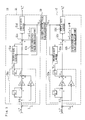
- the d-axis target voltage calculation part 51 has a d-axis PI calculation part 51a, a d-axis correction value calculation part 51b, a d-axis addition part 51c, a first d-axis limiter 51d, and a second d-axis limiter 51e.
- the d-axis PI calculation part 51a calculates a value V do by the PI calculation for the d-axis current, and outputs the result V do of the PI calculation to the d-axis addition part 51c and the second d-axis limiter 51e.
- K P is a proportional gain
- K I is an integral gain
- Z -1 is a preceding value of signal.
- the d-axis correction value calculation part 51b determines a d-axis correction value - ⁇ L q I q based on the variation rate of the detected rotation position obtained with the resovler 2 and the q-axis current I q determined with the dq-axes current calculation part 17, where ⁇ stands for a rotation speed (rad/sec) of the rotor 1b and Lq stands for a q-axis self-inductance of the armature winding of the motor 1.
- the d-axis addition part 51c adds the d-axis correction value - ⁇ L q I q to the result V do of the PI calculation for the d-axis current.
- the first d-axis limiter 51d limits an absolute value of the sum of the d-axis correction value - ⁇ L q I q and the result V do of the PI calculation for the d-axis current to the d-axis limiting value V Ld .
- the output value of the first d-axis limiter 51d is treated as the d-axis target value V d *.
- the d-axis target value V d * is determined based on the value obtained by correcting the result V do of the PI calculation for the d-axis current with the d-axis correction value - ⁇ L q I q .
- the second d-axis limiter 51e limits an absolute value of the result V do of the PI calculation for the d-axis current that is used as a preceding value of the PI calculation in the next calculation cycle to the d-axis limiting value V Ld .
- the output value V do ' of the second d-axis limiter 51e is used as a preceding value of the PI calculation for the d-axis current in the next calculation cycle.
- the q-axis target voltage calculation part 52 has a q-axis PI calculation part 52a, a q-axis correction value calculation part 52b, a q-axis addition part 52c, a first q-axis limiter 52d, and a second q-axis limiter 52e.
- the q-axis PI calculation part 52a calculates a value V qo by the PI calculation for the q-axis current, and outputs the result V qo of the PI calculation to the q-axis addition part 52c and the second q-axis limiter 52e.
- K P is a proportional gain
- K I is an integral gain
- Z -1 is a preceding value of signal.
- the q-axis correction value calculation part 52b determines a q-axis correction value ⁇ L d I d + ⁇ based on the variation rate of the detected rotation position obtained with the resovler 2 and the d-axis current I d determined with the dq-axes current calculation part 17, where ⁇ stands for a rotation speed (rad/sec) of the rotor 1b, L d stands for a d-axis self-inductance of the armature winding of the motor 1, and ⁇ stands for a value obtained by multiplying a maximum value of magnetic flux linkage of the armature winding in the field system of the rotor 1b by a factor of (3/2) 1/2 .
- the q-axis addition part 52c adds the q-axis correction value ⁇ L d I d + ⁇ to the result V qo of the PI calculation for the q-axis current.
- the first q-axis limiter 52d limits an absolute value of the sum of the q-axis correction value ⁇ L d I d + ⁇ and the result V qo of the PI calculation for the q-axis current to the q-axis limiting value V Lq .
- the output value of the first q-axis limiter 52d is treated as the q-axis target value Vq*.
- the q-axis target value V q * is determined based on the value obtained by correcting the result V qo of the PI calculation for the q-axis current with the q-axis correction value ⁇ L d I d + ⁇ .
- the second q-axis limiter 52e limits an absolute value of the result V qo of the PI calculation for the q-axis current that is used as a preceding value of the PI calculation in the next calculation cycle to the q-axis limiting value V Lq .
- the output value V qo ' of the second q-axis limiter 52e is used as a preceding value of the PI calculation for the q-axis current in the next calculation cycle.
- the flowchart of FIG. 5 shows a control procedure of the motor 1 with the controller 10.
- the detection values of the torque sensor 7, the vehicle velocity sensor 8, and the current detectors 11u, 11v, 11w are read (step S1)
- the target current I* is calculated in the basic target current calculation part 15 based on the detected steering torque and the vehicle velocity (step S2)
- the d-axis target current I d * and the q-axis target current I q * corresponding to the target current I* are calculated in the dq-axes target current calculation part 16 (step S3)
- the d-axis current I d and the q-axis current I q corresponding to the detected phase currents I u , I v , I w are calculated in the dq-axes current calculation part 17 (step S4)
- the d-axis difference ⁇ I d is calculated in the d-axis difference calculation part 18d from the d-axis target current I d * and the d-axis current I
- the flowcharts of FIG. 6A and FIG. 6B show the calculation procedure of the d-axis target voltage V d * and the q-axis target voltage V q * at the above-described step S6 in the first embodiment.
- the results V do , V qo of the PI calculations are determined by the PI calculation for the d-axis current and the PI calculation for the q-axis current (step S101)
- the d-axis correction value - ⁇ L q I q is determined in the d-axis correction value calculation part 51b
- the q-axis correction value (i)L d I d + ⁇ is determined in the q-axis correction value calculation part 52b
- the correction is performed by adding the d-axis correction value - ⁇ L q I q to the result V do of the PI calculation for the d-axis current and adding the q-axis correction value ⁇ L d I d + ⁇ to the result V qo of the
- a limiting process is performed in which an absolute value of V do - ⁇ L q I q , which is a value obtained by correcting the result of the PI calculation in the d-axis, is limited to the d-axis limiting value V Ld by the first d-axis limiter 51d, and an absolute value of V qo + ⁇ L d I d + ⁇ , which is a value obtained by correcting the result of the PI calculation in the q-axis, is limited to the q-axis limiting value V Lq by the first q-axis limiter 52d.
- V do - ⁇ L q I q is judged (step S105), and if it is equal to or less than V Ld , the V do - ⁇ L q I q is outputted as the d-axis target voltage V d * (step S106), and if it is not equal to or lower than V Ld , a judgment is made as to whether or not the V do - ⁇ L q I q is positive (step S107).
- V Ld is outputted as the d-axis target voltage V d * (step S108), and if it is not positive, -V Ld is outputted as the d-axis target voltage V d * (step S109). Furthermore, a judgment is made as to whether or not the absolute value of V qo + ⁇ L d I d + ⁇ is equal to or less than V Lq (step S110), and if it is equal to or less than V Lq , then V qo + ⁇ L d I d + ⁇ is outputted as the q-axis target voltage V q * (step S111), and if it is not equal to or less than V Lq , then a judgment is made as to whether or not the V qo + ⁇ L d I d + ⁇ is positive (step S112).
- V Lq is outputted as the q-axis target voltage V q * (step S113), and if it is not positive, then -V Lq is outputted as the q-axis target voltage V q * (step S114).
- the absolute value of the result V do of the PI calculation for the d-axis current that is used as a preceding value of the PI calculation in the next calculation cycle is limited to the d-axis limiting value V Ld by the second d-axis limiter 51e
- the absolute value of the result V qo of the PI calculation for the q-axis current that is used as a preceding value of the PI calculation in the next calculation cycle is limited to the q-axis limiting value V Lq by the second q-axis limiter 52e.
- V do is taken as an output value V do ' of the second d-axis limiter 51e and stored to be used as a preceding value of the PI calculation in the next calculation cycle (step S116). If it is not equal to or less than V Ld , then whether or not V do is positive is judged (step S117).
- V Ld is taken as an output value V do ' of the second d-axis limiter 51e and stored to be used as a preceding value of the PI calculation in the next calculation cycle (step S118), if it is not positive, then -V Ld is taken as an output value V do ' of the second d-axis limiter 51e and stored to be used as a preceding value of the PI calculation in the next calculation cycle (step 5119).
- V qo is taken as an output value V qo ' of the second q-axis limiter 52e and stored to be used as a preceding value of the PI calculation in the next calculation cycle (step S121), and if it is not equal to or less than V Lq , then whether or not V qo is positive is judged (step S122).
- V Lq is taken as an output value V qo ' of the second q-axis limiter 52e and stored to be used as a preceding value of the PI calculation in the next calculation cycle (step S123), and if it is not positive, then -V Lq is taken as an output value V qo ' of the second q-axis limiter 52e and stored to be used as a preceding value of the PI calculation in the next calculation cycle (step S124), followed by the return.
- the d-axis target voltage V d * is determined based on the value obtained by correcting the result V do of the PI calculation for the d-axis current with the d-axis correction value - ⁇ L q I q , so that the influence on the responsiveness of the motor 1 due to the difference between the d-axis target voltage V d * and the d-axis voltage V d arising in accordance with the rotation speed ⁇ and the q-axis current I q can be reduced by comparison with the case where no such correction is made.
- the q-axis target voltage V q * is determined based on the value obtained by correcting the result V qo of the PI calculation for the q-axis current with the q-axis correction value ⁇ L d I d + ⁇ , so that the influence on the responsiveness of the motor 1 due to the difference between the q-axis target voltage V q * and the q-axis voltage V q arising in accordance with the rotation speed ⁇ , the d-axis current I d , and the magnetic flux ⁇ can be reduced by comparison with the case where no such correction is made.
- the absolute value of the sum of the d-axis correction value - ⁇ L q I q and the result V do of the PI calculation for the d-axis current is limited to the d-axis limiting value V Ld by the first d-axis limit 51d.
- the d-axis target voltage V d * can be determined based on this value limited by the first d-axis limiter 51d, that is, based on the output value of the first d-axis limiter 51d.
- the absolute value of the result V do of the PI calculation for the d-axis current is limited to the d-axis limiting value V Ld by the second d-axis limiter 51e.
- This value limited by the second d-axis limiter 51e that is, the output value V do ' of the second d-axis limiter 51e, can be used as a preceding value of the PI calculation for the d-axis current in the next calculation cycle.
- the result V do of the PI calculation for the d-axis current can be corrected and the preceding value of the PI calculation in the next calculation cycle can be limited by the second d-axis limiter 51e, without unnecessarily decreasing the absolute value of the d-axis target voltage V d * and without adding the correction value to the preceding value of the PI calculation in the next calculation cycle.
- the absolute value of the sum of the q-axis correction value ⁇ L d I d + ⁇ and the result V qo of the PI calculation for the q-axis current is limited to the q-axis limiting value V Lq by the first q-axis limiter 52d.
- the q-axis target voltage V q * can be determined based on this value limited by the first q-axis limiter 52d, that is, based on the output value of the first q-axis limiter 52d.
- the absolute value of the result V qo of the PI calculation for the q-axis current is limited to the q-axis limiting value V Lq by the second q-axis limiter 52e.
- This value limited by the second q-axis limiter 52e that is, the output value V qo ' of the second q-axis limiter 52e, can be used as a preceding value of the PI calculation for the q-axis current in the next calculation cycle.
- the result V qo of the PI calculation for the q-axis current can be corrected and the preceding value of the PI calculation in the next calculation cycle can be limited by the second q-axis limiter 52e, without unnecessarily decreasing the absolute value of the q-axis target voltage V q * and without adding the correction value to the preceding value of the PI calculation in the next calculation cycle.
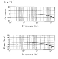
- FIG. 7A and FIG. 7B are bode diagrams illustrating the frequency response characteristic of the q-axis current relative to the q-axis target current in a case where the rotation speed of the brushless motor is 1500 rpm.
- FIG. 7A illustrates a comparative example in which the correction of the result of the PI calculation is not performed
- FIG. 7B illustrates a case where the correction is performed as in the above-described embodiment.
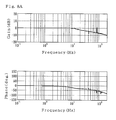
- FIG. 8A and FIG. 8B are bode diagrams illustrating the frequency response characteristic of the q-axis current relative to the q-axis target current in a case where the rotation speed of the brushless motor is 500 rpm.
- FIG. 7A illustrates a comparative example in which the correction of the result of the PI calculation is not performed
- FIG. 7B illustrates a case where the correction is performed as in the above-described embodiment.
- FIG. 8A and FIG. 8B are bode diagrams illustrating the frequency response characteristic of the q-axis current relative to
- FIG. 8A illustrates a comparative example in which the correction of the result of the PI calculation is not performed
- FIG. 8B illustrates a case where the correction is performed as in the above-described embodiment. It is confirmed by the bode diagrams that the influence of rotation speed on the responsiveness of the brushless motor can be reduced, and the responsiveness can be stabilized.
- a controller for brushless motor of the second embodiment of the present invention is described below with reference to FIG. 9 and FIG. 10.
- the explanation of components identical to those of the first embodiment is omitted and differences between the embodiments are explained.
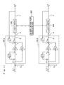
- a dq-axes target voltage calculation part 19' of the second embodiment has a dq-axes limiting value calculation part 50, a d-axis target voltage calculation part 51', and a q-axis target voltage calculation part 52'.
- the d-axis target voltage calculation part 51' determines a d-axis target voltage V d * based on the PI calculation for the d-axis current so as to decrease the d-axis difference ⁇ I d .
- the q-axis target voltage calculation part 52' determines a q-axis target voltage V q * based on the PI calculation for the q-axis current so as to decrease the q-axis difference ⁇ I q .
- the dq-axes limiting value calculation part 50 of the second embodiment determines a d-axis limiting value V Ld and a q-axis limiting value V Lq such that the target applied voltages to the armature winding of the motor 1 do not exceed a set maximum value V max and the waveform representing the variation of the voltage applied to the armature winding relative to the variation of the rotation position of the rotor 1b becomes a sine wave rather than a discontinuous wave.
- the d-axis target voltage calculation part 51' has a d-axis PI calculation part 51a', a d-axis correction value calculation part 51b', a d-axis addition part 51c', a d-axis limiter 51d', and a d-axis corrected limiting value calculation part 51f.
- the d-axis PI calculation part 51a' calculates a value V do by the PI calculation for the d-axis current, and outputs the result V do of the PI calculation to the d-axis limiter 51d'.
- the d-axis correction value calculation part 51b' determines a d-axis correction value - ⁇ L q I q and also determines an absolute value of the d-axis correction value - ⁇ L q I q .
- the d-axis corrected limiting value calculation part 51f determines a d-axis corrected limiting value V Ld ' by subtracting the absolute value of the d-axis correction value - ⁇ L q I q from the d-axis limiting value V Ld .
- the d-axis limiter 51d' limits the absolute value of the result V do of the PI calculation for the d-axis current to the d-axis corrected limiting value V Ld '.
- the d-axis addition part 51c' adds the d-axis correction value - ⁇ L q I q to an output value V do " of the d-axis limiter 51d'.
- the output value of the d-axis addition part 51c' is treated as the d-axis target value V d *.
- the d-axis target value V d * is determined based on the value obtained by correcting the limited result V do of the PI calculation for the d-axis current with the d-axis correction value ⁇ L q I q .
- the output value V do " of the d-axis limiter 51d' is used as a preceding value of the PI calculation for the d-axis current in the next calculation cycle.
- the q-axis target voltage calculation part 52' has a q-axis PI calculation part 52a', a q-axis correction value calculation part 52b', a q-axis addition part 52c', a q-axis limiter 52d', and a q-axis corrected limiting value calculation part 52f.
- the q-axis PI calculation part 52a' calculates a value V qo by the PI calculation for the q-axis current, and outputs the result V qo of the PI calculation to the q-axis limiter 52d'.
- the q-axis correction value calculation part 52b' determines a q-axis correction value ⁇ L d I d + ⁇ and also determines an absolute value of the q-axis correction value ⁇ L d I d + ⁇ .
- the q-axis corrected limiting value calculation part 52f determines a q-axis corrected limiting value V Lq ' by subtracting the absolute value of the q-axis correction value ⁇ L d I d + ⁇ from the q-axis limiting value V Lq .
- the q-axis limiter 52d' limits the absolute value of the result V qo of the PI calculation for the q-axis current to the q-axis corrected limiting value V Lq '.
- the q-axis addition part 52c' adds the q-axis correction value ⁇ L d I d + ⁇ to the output value V qo " of the q-axis limiter 52d'.
- the output value of the q-axis addition part 52c' is treated as the q-axis target value Vq*.
- the q-axis target value V q * is determined based on the value obtained by correcting the limited result V qo of the PI calculation for the q-axis current with the q-axis correction value ⁇ L d I d + ⁇ .
- the output value V qo " of the q-axis limiter 52d' is used as a preceding value of the PI calculation for the q-axis current in the next calculation cycle.
- the flowchart of FIG. 10 shows a calculation procedure of the d-axis target voltage V d * and the q-axis target voltage V q * at the above-described step S6 in the second embodiment.
- results V do V qo of the PI calculation are determined by the PI calculation for the d-axis current and the PI calculation for the q-axis current (step S201)
- a d-axis correction value - ⁇ L q I q is determined in the d-axis correction value calculation part 51b'
- a q-axis correction value ⁇ L d I d + ⁇ is determined in the q-axis correction value calculation part 52b' (step S202).
- a d-axis limiting value V Ld and a q-axis limiting value V Lq are calculated (step S203), a d-axis corrected limiting value V Ld ' is determined in the d-axis corrected limiting value calculation part 51f by subtracting the absolute value of the d-axis correction value - ⁇ L q I q from the d-axis limiting value V Ld , and a q-axis corrected limiting value V Lq ' is determined in the q-axis corrected limiting value calculation part 52f by subtracting the absolute value of the q-axis correction value ⁇ L d I d + ⁇ from the q-axis limiting value V Lq (step S204).
- the absolute value of the result V do of the PI calculation for the d-axis current that is used as a preceding value of the PI calculation in the next calculation cycle is limited to the d-axis corrected limiting value V Ld ' by the d-axis limiter 51d', and the absolute value of the result V qo of the PI calculation for the q-axis current that is used as a preceding value of the PI calculation in the next calculation cycle is limited to the q-axis corrected limiting value V Lq ' by the q-axis limiter 52d'.
- V do is taken as the output value V do " of the d-axis limiter 51d' and stored to be used as a preceding value of the PI calculation in the next calculation cycle (step S206), if it is not equal to or lower than V Ld ', a judgment is made as to whether or not the V do is positive (step S207).
- V Ld is taken as the output value V do " of the d-axis limiter 51d' and stored to be used as a preceding value of the PI calculation in the next calculation cycle (step S208), and if it is not positive, -V Ld is taken as the output value V do " of the d-axis limiter 51d' and stored to be used as a preceding value of the PI calculation in the next calculation cycle (step S209).
- V qo is taken as the output value V qo " of the q-axis limiter 52d' and stored to be used as a preceding value of the PI calculation in the next calculation cycle (step S211), if it is not equal to or lower than V Lq ', a judgment is made as to whether or not the V qo is positive (step S212).
- V Lq is taken as the output value V qo " of the q-axis limiter 52d' and stored to be used as a preceding value of the PI calculation in the next calculation cycle (step S213), and if it is not positive, -V Lq is taken as the output value V qo " of the q-axis limiter 52d' and stored to be used as a preceding value of the PI calculation in the next calculation cycle (step S214).
- a value obtained by adding the d-axis correction value - ⁇ L q I q to the output value V do " of the d-axis limiter 51d' in the d-axis addition part 51c' is outputted as the d-axis target voltage V d * (step S215), and a value obtained by adding the q-axis correction value ⁇ L d I d + ⁇ to the output value V qo " of the q-axis limiter 52d' in the q-axis addition part 52c' is outputted as the q-axis target voltage V q * (step S216), followed by the return.
- the d-axis corrected limiting value V Ld ' that is obtained by subtracting the absolute value of d-axis correction value - ⁇ L q I q from the d-axis limiting value V Ld is determined with the d-axis corrected limiting value calculation part 51f, and the absolute value of the result V do of the PI calculation for the d-axis current is limited to the d-axis corrected limiting value V Ld ' by the d-axis limiter 51d'.
- This value limited by the d-axis limiter 51d' that is the output value V do " of the d-axis limiter 51d', can be used as a preceding value of the PI calculation for the d-axis current in the next calculation cycle. Further, the d-axis target voltage V d * can be determined based on a value obtained by adding the d-axis correction value - ⁇ L q I q to the output value V do " of the d-axis limiter 51d', that is, based on the output value of the d-axis addition part 51c'.
- the result V do of the PI calculation for the d-axis current can be corrected and the preceding value of the PI calculation for the d-axis current in the next calculation cycle can be limited by the d-axis limiter 51d', without unnecessarily decreasing the absolute value of the d-axis target voltage V d * and without adding the correction value to the preceding value of the PI calculation for the d-axis current in the next calculation cycle.
- the preceding value of the PI calculation for the d-axis current in the next calculation cycle is limited to the d-axis corrected limiting value V Ld ' rather than to the d-axis limiting value V Ld .
- the d-axis limiting value V Ld is determined such that it does not exceed the set maximum value of the target voltages applied to the armature winding of motor 1. Further, when one of the d-axis voltage V d and the q-axis voltage V q increases, the other decreases, and the d-axis correction value - wL q I q correlates with the q-axis current I q . Therefore, the d-axis corrected limiting value V Ld ' obtained by subtracting the absolute value of the d-axis correction value - ⁇ L q I q from the d-axis limiting value V Ld can be brought close to the actual maximum value that can be applied to the armature winding.
- the preceding value of the PI calculation for the d-axis current in the next calculation cycle is prevented from being limited to an unnecessarily large limiting value, and the convergence ability of the result V do of the PI calculation for the d-axis can be improved.
- the q-axis corrected limiting value V Lq ' that is obtained by subtracting the absolute value of the q-axis correction value ⁇ L d I d + ⁇ from the q-axis limiting value V Lq is determined with the q-axis corrected limiting value calculation part 52f, and the absolute value of the result V qo of the PI calculation for the q-axis current is limited to the q-axis corrected limiting value V Lq ' by the q-axis limiter 52d'.
- This value limited by the q-axis limiter 52d' that is the output value V qo " of the q-axis limiter 52d', can be used as a preceding value of the PI calculation for the q-axis current in the next calculation cycle. Further, the q-axis target voltage V q * can be determined based on the value obtained by adding the q-axis correction value ⁇ L d I d + ⁇ to the result of the PI calculation limited by the q-axis limiter 52d', that is, based on the output value of the q-axis addition part 52c'.
- the result V qo of the PI calculation for the q-axis current can be corrected and the preceding value of the PI calculation for the q-axis current in the next calculation cycle can be limited by the q-axis limiter 52d', without unnecessarily decreasing the absolute value of the q-axis target voltage V q * and without adding the correction value to the preceding value of the PI calculation for the q-axis current in the next calculation cycle.
- the preceding value of the PI calculation for the q-axis current in the next calculation cycle is limited to the q-axis corrected limiting value V Lq ' rather than to the q-axis limiting value V Lq .
- the q-axis limiting value V Lq is determined such that it does not exceed the set maximum value of the target voltages applied to the armature winding. Further, when one of the d-axis voltage V d and q-axis voltage V q increases, the other decreases, and the q-axis correction value ⁇ L d I d + ⁇ correlates with the d-axis current I d .
- the q-axis corrected limiting value V Lq ' obtained by subtracting the absolute value of the q-axis correction value ⁇ L d I d + ⁇ from the q-axis limiting value V Lq can be brought close to the actual maximum value that can be applied to the armature winding.
- the preceding value of the PI calculation for the q-axis current in the next calculation cycle is prevented from being limited to an unnecessarily large limiting value, and convergence ability of the result V qo of the PI calculation in the q-axis can be improved.
- ⁇ L d I d can be used instead of ⁇ L d I d + ⁇ as the q-axis correction value determined by the q-axis correction value calculation parts 52b, 52b', other features being identical to those of the embodiment.
- the q-axis target voltage V q * is determined based on a value obtained by correcting the result V qo of the PI calculation for the q-axis current with the q-axis correction value ⁇ L d I d , and the influence on the responsiveness of the motor 1 due to the difference between the q-axis target voltage V q * and the q-axis voltage V q occurring arising in accordance with the rotation speed ⁇ and the d-axis current I d can be also reduced by comparison with the case where no such correction is made.
- the present invention is not limited to the above-described embodiments.
- the feedback calculation for decreasing the d-axis difference and the q-axis difference is not limited to the PI calculation of the embodiments, and other feedback calculation such as the P calculation or the PID calculation can be used, provided that the differences are decreased.
- the brushless motor is not limited to a three-phase configuration, and the application thereof is not limited to the generation of steering assist power.
Landscapes
- Engineering & Computer Science (AREA)
- Power Engineering (AREA)
- Control Of Ac Motors In General (AREA)
Abstract
Description
- The present invention relates to a controller for a brushless motor that determines differences between target currents and detected currents in a dq coordinate system and determines a target voltage applied to an armature winding based on a feedback calculation, such as PI (Proportional Integral) calculation, P (Proportional) calculation, or PID (Proportional Integral Derivative) calculation, to decrease the differences.
- A conventional controller for a brushless motor comprises a current detection part that detects currents flowing in the armature winding, a rotation position detection part that detects a rotation position of a rotor of the motor, a dq-axes target current calculation part that calculates a d-axis target current and a q-axis target current, a dq-axes current calculation part that determines a d-axis current and a q-axis current based on the detected currents and the detected rotation position, a d-axis target voltage calculation part that determines a d-axis target voltage based on the PI calculation for the d-axis current so as to decrease a d-axis difference between the d-axis target current and the d-axis current, and a q-axis target voltage calculation part that determines a q-axis target voltage based on the PI calculation for the q-axis current so as to decrease a q-axis difference between the q-axis target current and the q-axis current, in which the controller generates the rotation force of the rotor by applying the voltage to the armature winding based on the d-axis target voltage, q-axis target voltage, and the detected rotation position (
Japanese Patent Application Laid-open No. 2001-187578 - When the dq-axes target voltages are determined based on the results of the PI calculation, limiters for limiting the target voltages are required to prevent the target voltage applied to the armature winding from exceeding a maximum set value, with preventing the waveform representing the variation of voltage applied to the armature winding relative to the variation of the rotation position of the rotor from being discontinuous. If the limiters are not provided, the results of the PI calculation continuously increase in a case where the differences between the target currents and the detected currents are not decreased. As a result, a certain time is required for the target voltages corresponding to the results of the PI calculation to reach appropriate values even when the differences decrease. Further, because the maximum voltage that can be applied to the armature winding is regulated according to, e.g., the power source capacity, the waveform representing the variation of voltage applied to the armature winding relative to the variation of the rotation position of the rotor becomes discontinuous when the target voltages becomes too high. For example, the waveform assumes a shape obtained by clipping the vicinity of peaks of the sine wave, thereby causing abnormal noise or vibrations.
- In a comparative example represented by the block diagram in FIG. 11, a d-axis difference δId between a d-axis target current Id* and a d-axis current Id is determined in a d-axis
PI calculation part 101a, a result Vdo of the PI calculation is determined by performing the PI calculation, a q-axis difference δIq between a q-axis target current Iq* and a q-axis current Iq is determined in a q-axisPI calculation part 101b, and a result Vqo of the PI calculation is determined by performing the PI calculation. In a dq-axes limitingvalue calculation part 102, a d-axis limiting value and a q-axis limiting value are determined such that the target voltage applied to the armature winding does not exceed a set maximum value and a waveform representing the variation of the voltage applied to the armature winding relative to the variation of the rotation position of the rotor do not become discontinuous. A d-axis target voltage Vd* is determined by limiting the absolute value of the result Vdo of the PI calculation for the d-axis current with a d-axis limiter 103 so that the absolute value becomes equal to or less than the d-axis limiting value, and a q-axis target voltage Vq* is determined by limiting the absolute value of the result Vqo of the PI calculation for the q-axis current with a q-axis limiter 104 so that the absolute value becomes equal to or less than the q-axis limiting value. Here, the output value of the d-axis limiter 103 is used as a preceding value of the PI calculation for the d-axis current in the next calculation cycle, and the output value of the q-limiter 104 is used as a preceding value of the PI calculation for the q-axis current in the next calculation cycle. In the figure, KP is a proportional gain, KI is an integral gain, and Z-1 is a preceding value of signal. - In the conventional controller, the responsiveness of the brushless motor fluctuates according to the rotation speed and current value even if the above-described limiters are provided, therefore stable responsiveness cannot be obtained. It is an object of the present invention to provide a controller for a brushless motor that can resolve such a problem.
- A controller for a brushless motor to which the present invention is applied comprises a current detection part that detect a current flowing in an armature winding of the brushless motor, a rotation position detection part that detects a rotation position of a rotor of the motor, a dq-axes target current calculation part that calculates a d-axis target current and a q-axis target current, where an axis along a magnetic flux direction of a field system of the rotor is taken as the d axis and an axis perpendicular to the d axis and a rotation axis of the rotor is taken as the q axis, a dq-axes current calculation part that determines a d-axis current and a q-axis current based on the detected current and the detected rotation position, a d-axis target voltage calculation part that determines a d-axis target voltage based on a feedback calculation for the d-axis current so as to decrease a d-axis difference between the d-axis target current and the d-axis current, and a q-axis target voltage calculation part that determines a q-axis target voltage based on a feedback calculation for the q-axis current so as to decrease a q-axis difference between the q-axis target current and the q-axis current, in which a rotation force of the rotor is generated by applying a voltage to the armature winding based on the d-axis target voltage, the q-axis target voltage, and the detected rotation position.
- The first feature of the present invention is that a d-axis correction value calculation part for determining a d-axis correction value -ωLqIq and a q-axis correction value calculation part for determining a q-axis correction value ωLdId + ωΦ are provided, the d-axis target voltage is determined based on a value obtained by correcting a result of the feedback calculation for the d-axis current with the d-axis correction value -ωLqIq, and the q-axis target voltage is determined based on a value obtained by correcting a result of the feedback calculation for the q-axis current with the q-axis correction value ωLdId + ωΦ.
- The second feature of the present invention is that a d-axis correction value calculation part for determining a d-axis correction value -ωLqIq and a q-axis correction value calculation part for determining a q-axis correction value ωLdId, are provided, the d-axis target voltage is determined based on a value obtained by correcting a result of the feedback calculation for the d-axis current with the d-axis correction value -ωLqIq, and the q-axis target voltage is determined based on a value obtained by correcting a result of the feedback calculation for the q-axis current with the q-axis correction value ωLdId.
- In the present invention, ω stands for a rotation speed (rad/sec) of the rotor, Ld stands for a d-axis self-inductance of the armature winding, Lq stands for a q-axis self-inductance of the armature winding, Id stands for the d-axis current, Iq stands for the q-axis current, and Φ stands for a value obtained by multiplying a maximum value of magnetic flux linkage of the armature winding in the field system by a factor of (3/2)1/2.
- The d-axis voltage Vd and the q-axis voltage Vq can be approximately determined from the following formulas, where R stands for a resistance of the armature wiring, and P stands for a differential operator:


- Therefore, using either feature of the present invention makes it possible to determine the d-axis target voltage based on the value obtained by correcting the result of the feedback calculation for the d-axis current with the d-axis correction value -ωLqIq, so that the influence on the responsiveness of the brushless motor due to the difference between the d-axis target voltage and the d-axis voltage arising in accordance with the rotation speed ω and the q-axis current Iq can be reduced by comparison with the case where no such correction is made.
- Using the first feature of the present invention makes it possible to determine the q-axis target voltage based on the value obtained by correcting the result of the feedback calculation for the q-axis current with the q-axis correction value ωLdId + ωΦ, so that the influence on the responsiveness of the brushless motor due to the difference between the q-axis target voltage and the q-axis voltage arising in accordance with the rotation speed ω, the d-axis current Id, and the magnetic flux Φ can be reduced by comparison with the case where no such correction is made.
- Using the second feature of the present invention makes it possible to determine the q-axis target voltage based on the value obtained by correcting the result of the feedback calculation for the q-axis current with the q-axis correction value ωLdId, so that the influence on the responsiveness of the brushless motor due to the difference between the q-axis target voltage and the q-axis voltage arising in accordance with the rotation speed ω and the d-axis current Id can be reduced by comparison with the case where no such correction is made.
- As a result, the responsiveness of the brushless motor can be prevented from fluctuating even if the rotation speed and/or the current value change.
- In the comparative example shown in FIG. 11, limiting the absolute value of the result Vdo of the PI calculation for the d-axis current to the d-axis limiting value with the single d-
axis limiter 103 and limiting an absolute value of the result Vqo of the PI calculation for the q-axis current to the q-axis limiting value with the single q-axis limiter 104 are fulfilled; it suffices to determine the d-axis limiting value and the q-axis limiting value such that the target voltage applied to the armature winding does not exceed a set maximum value and the waveform representing the variation of the voltage applied to the armature winding relative to the variation of the rotation position of the rotor does not become a discontinuous wave. - However, the d-axis target voltage cannot be determined correctly when the result of the PI calculation for the d-axis current is corrected with the d-axis correction value, if the d-axis limiting value is determined without respect to the d-axis correction value and the result of the PI calculation for the d-axis current is limited with a single d-axis limiter. Thus, a case may by considered in which an absolute value of a value obtained by correcting the result of the PI calculation for the d-axis current with the d-axis correction value is limited to the d-axis limiting value by a single d-axis limiter and the output value of the d-axis limiter is used as a preceding value of the PI calculation for the d-axis current in the next calculation cycle (for example, in this case, the d-axis correction value is added to the result of the PI calculation for the d-axis current at the point of α in FIG. 11). In this case, the correction value is added to the value used as the preceding value of the PI calculation in the next calculation cycle, so that there is a problem that the PI calculation cannot be performed appropriately. To resolve this problem, a case may be considered in which the result of the PI calculation for the d-axis current that is not corrected is used as the preceding value of the PI calculation for the d-axis current in the next calculation cycle (for example, in this case, the d-axis correction value is added to the result of the PI calculation for the d-axis current at the point of α in FIG. 11, and the result of the PI calculation for the d-axis current at the point of β is used as the preceding value of the PI calculation in the next calculation cycle as shown by a broken line). In this case, the preceding value of the PI calculation in the next calculation cycle cannot be limited by the d-
axis limiter 103, so that there is a problem that the result of the PI calculation continues to increase when the difference between the target current and the detected current does not decrease. Further, a case may be considered in which the absolute value of the result of the PI calculation for the d-axis current that is not corrected is limited to the d-axis limiting value by a single d-axis limiter (for example, in this case, the d-axis correction value is added to the result of the PI calculation for the d-axis current at the point of Υ in FIG. 11). In this case, if the positive or negative of the d-axis correction value is set to decrease the absolute value of the d-axis target voltage, the absolute value of the d-axis target voltage is further decreased by the correction after being decreased by the d-axis limiter 103. Thus, the absolute value of the d-axis target voltage is unnecessarily decreased, so that there is a problem that the power source voltage cannot be used effectively. The same problem arises when the result of the PI calculation for the q-axis current is corrected with the q-axis correction value. - Hence, in the present invention, the above-described controller preferably comprises a dq-axes limiting value calculation part that determines a d-axis limiting value and a q-axis limiting value so that a target voltage applied to the armature winding does not exceed a set maximum value, a d-axis addition part that adds the d-axis correction value to the result of the feedback calculation for the d-axis current, a q-axis addition part that adds the q-axis correction value to the result of the feedback calculation for the q-axis current, a first d-axis limiter that limits an absolute value the sum of the d-axis correction value and the result of the feedback calculation for the d-axis current to the d-axis limiting value, a second d-axis limiter that limits an absolute value of the result of the feedback calculation for the d-axis current to the d-axis limiting value, a first q-axis limiter that limits an absolute value of the sum of the q-axis correction value and the result of the feedback calculation for the q-axis current to the q-axis limiting value, and a second q-axis limiter that limits an absolute value of the result of the feedback calculation for the q-axis current to the q-axis limiting value, wherein an output value of the first d-axis limiter is treated as the d-axis target voltage, an output value of the first q-axis limiter is treated as the q-axis target voltage, an output value of the second d-axis limiter is used as a preceding value of the feedback calculation for the d-axis current in a next calculation cycle, and an output value of the second q-axis limiter is used as a preceding value of the feedback calculation for the q-axis current in a next calculation cycle.
- As a result, the absolute value of the sum of the d-axis correction value and the result of the feedback calculation for the d-axis current is limited to the d-axis limiting value by the first d-axis limiter. The d-axis target voltage can be determined based on the value limited by the first d-axis limiter, that is, the output value of the first d-axis limiter. Further, the absolute value of the result of the feedback calculation for the d-axis current is limited to the d-axis limiting value by the second d-axis limiter. The value limited by the second d-axis limiter, that is, the output value of the second d-axis limiter, can be used as a preceding value of the feedback calculation for the d-axis current in the next calculation cycle. Therefore, the result of the feedback calculation for the d-axis current can be corrected and the preceding value of the feedback calculation in the next calculation cycle can be limited to the d-axis limiting value, without unnecessarily decreasing the absolute value of the d-axis target value and without adding the correction value to the preceding value of the feedback calculation in the next calculation cycle.
- Likewise, the absolute value of the sum of the q-axis correction value and the result of the feedback calculation for the q-axis current is limited to the q-axis limiting value by the first q-axis limiter. The q-axis target voltage can be determined based on the value limited to the first q-axis limiter, that is, the output value of the first q-axis limiter. Further, the absolute value of the result of the feedback calculation for the q-axis current is limited to the q-axis limiting value by the second q-axis limiter. The value limited by the second q-axis limiter, that is, the output value of the second q-axis limiter, can be used as a preceding value of the feedback calculation for the q-axis current in the next calculation cycle. Therefore, the result of feedback calculation for the q-axis current can be corrected and the preceding value of the feedback calculation in the next calculation cycle can be limited to the q-axis limiting value, without unnecessarily decreasing the absolute value of the q-axis target value and without adding the correction value to the preceding value of the feedback calculation in the next calculation cycle.
- Alternatively, in the present invention, the above-described controller preferably comprises a dq-axes limiting value calculation part that determines a d-axis limiting value and a q-axis limiting value so that a target voltage applied to the armature winding does not exceed a set maximum value, a d-axis corrected limiting value calculation part that determines a d-axis corrected limiting value that is obtained by subtracting an absolute value of the d-axis correction value from the d-axis limiting value, a q-axis corrected limiting value calculation part that determines a q-axis corrected limiting value that is obtained by subtracting an absolute value of the q-axis correction value from the q-axis limiting value, a d-axis limiter that limits an absolute value of the result of the feedback calculation for the d-axis current to the d-axis corrected limiting value, a q-axis limiter that limits an absolute value of the result of the feedback calculation for the q-axis current to the q-axis corrected limiting value, a d-axis addition part that adds the d-axis correction value to an output value of the d-axis limiter, a q-axis addition part that adds the q-axis correction value to an output value of the q-axis limiter, wherein an output value of the d-axis addition part is treated as the d-axis target voltage, an output value of the q-axis addition part is treated as the q-axis target voltage, the output value of the d-axis limiter is used as a preceding value of the feedback calculation for the d-axis current in a next calculation cycle, and the output value of the q-axis limiter is used as a preceding value of the feedback calculation for the q-axis current in a next calculation cycle.
- As a result, the d-axis corrected limiting value that is obtained by subtracting the absolute value of the d-axis correction value from the d-axis limiting value is determined by the d-axis corrected limiting value calculation part, and the absolute value of the result of the feedback calculation for the d-axis current is limited to the d-axis corrected limiting value by the d-axis limiter. The value limited by the d-axis limiter, that is, the output value of the d-axis limiter, can be used as a preceding value of the feedback calculation for the d-axis current in the next calculation cycle. Further, the d-axis target voltage can be determined based on the value obtained by adding the d-axis correction value to the output value of the d-axis limiter, that is, based on the output value of the d-axis addition part. Therefore, the result of the feedback calculation for the d-axis current can be corrected and the preceding value of the feedback calculation for the d-axis current in the next calculation cycle can be limited by the d-axis limiter, without unnecessarily decreasing the absolute value of the d-axis target voltage and without adding the correction value to the preceding value of the feedback calculation for the d-axis current in the next calculation cycle.
- Moreover, the preceding value of the feedback calculation for the d-axis current in the next calculation cycle is limited to the d-axis corrected limiting value rather than to the d-axis limiting value. This d-axis limiting value is determined such that it does not exceed the set maximum value of the target voltage applied to the armature winding. Further, when one of the d-axis voltage and the q-axis voltage increases, the other decreases, and the d-axis correction value correlates with the q-axis current. Therefore, the d-axis corrected limiting value obtained by subtracting the absolute value of the d-axis correction value from the d-axis limiting value can be brought close to the actual maximum value that can be applied to the armature winding. Thus, the preceding value of the feedback calculation for the d-axis current in the next calculation cycle is prevented from being limited to an unnecessarily large limiting value, and the convergence ability of the result of the feedback calculation in the d-axis can be improved.
- Likewise, the q-axis corrected limiting value that is obtained by subtracting the absolute value of the q-axis correction value from the q-axis limiting value is determined by the q-axis corrected limiting value calculation part, and the absolute value of the result of the feedback calculation for the q-axis current is limited to the q-axis corrected limiting value by the q-axis limiter. The value limited by the q-axis limiter, that is, the output value of the q-axis limiter, can be used as the preceding value of the feedback calculation for the q-axis current in the next calculation cycle. The q-axis target voltage can be determined based on the value obtained by adding the q-axis correction value to the result of the feedback calculation for the q-axis current limited by the q-axis limiter with the q-axis addition part, that is, based on the output value of the q-axis addition part. Therefore, the result of the feedback calculation for the q-axis current can be corrected and the preceding value of the feedback calculation for the q-axis current in the next calculation cycle can be limited by the q-axis limiter, without unnecessarily decreasing the absolute value of the q-axis target voltage and without adding the correction value to the preceding value of the feedback calculation for the q-axis current in the next calculation cycle.
- Moreover, the preceding value of the feedback calculation for the q-axis current in the next calculation cycle is limited to the q-axis corrected limiting value rather than to the q-axis limiting value. The q-axis limiting value is determined such that it does not exceed the set maximum value of the target voltage applied to the armature winding. Further, when one of the d-axis voltage and the q-axis voltage increases, the other decreases, and the q-axis correction value correlates with the d-axis current. Therefore, the q-axis corrected limiting value obtained by subtracting the absolute value of the q-axis correction value from the q-axis limiting value can be brought close to the actual maximum value that can be applied to the armature winding. Thus, the preceding value of the feedback calculation for the q-axis current in the next calculation cycle is prevented from being limited to an unnecessarily large limiting value, and the convergence ability of the result of the feedback calculation in the q-axis can be improved.
- With the controller for a brushless motor according to the present invention, the responsiveness of the brushless motor can be stabilized with eliminating the influence of the rotation speed and/or the current value.
-
- FIG. 1 is a partial sectional view of an electric power steering apparatus of embodiments of the present invention.
- FIG. 2 is a schematic explanatory drawing of a controller of the embodiments of the present invention.
- FIG. 3 is a block-diagram illustrating the configuration of a dq-axes target voltage calculation part in the controller of the first embodiment of the present invention.
- FIG. 4 illustrates an example of relationship between the rotation position of the rotor and the target applied voltage.
- FIG. 5 is a flowchart illustrating the control procedure performed with the controller of the embodiment of the present invention.
- FIG. 6A is a flow chart illustrating the calculation procedure of the target voltage with the controller of the first embodiment of the present invention.
- FIG. 6B is a flow chart illustrating the calculation procedure of the target voltage with the controller of the first embodiment of the present invention.
- FIG. 7A is a bode diagram representing a frequency response characteristic of q-axis current relative to q-axis target current in a case where the rotation speed of the brushless motor of the comparative example is 1500 rpm.
- FIG. 7B is a bode diagram representing a frequency response characteristic of q-axis current relative to q-axis target current in a case where the rotation speed of the brushless motor of the first embodiment is 1500 rpm.
- FIG. 8A is a bode diagram representing a frequency response characteristic of q-axis current relative to q-axis target current in a case where the rotation speed of the brushless motor of the comparative example is 500 rpm.
- FIG. 8B is a bode diagram representing a frequency response characteristic of q-axis current relative to q-axis target current in a case where the rotation speed of the brushless motor of the first embodiment is 500 rpm.
- FIG. 9 is a block-diagram illustrating the configuration of a dq-axes target voltage calculation part in the controller of the second embodiment of the present invention.
- FIG. 10 is a flow chart illustrating the calculation procedure of the target voltage with the controller of the second embodiment of the present invention.
- FIG. 11 is a block diagram illustrating the configuration of a dq-axis target voltage calculation part in the controller of a brushless motor of the comparative example of the present invention.
- A controller for brushless motor of the first embodiment of the present invention is described below with reference to FIGS. 1 to 8B.
- An electric
power steering device 101 of a rack-pinion type for a vehicle that is shown in FIG. 1 comprises asteering shaft 103 that is rotated by steering operation, apinion 103a provided on thesteering shaft 103, arack 104 engaged with thepinion 103a, a three-phase brushless motor 1 for generating steering assist power, and ascrew mechanism 110 for transmitting the output of themotor 1 to therack 104. Each end of therack 104 is linked to a wheel (no shown in the figures). When thepinion 103a is rotated by steering operation, therack 104 moves in the widthwise direction of the vehicle, and the steering angle changes due to the movement of therack 104. - The
motor 1 comprises a stator 1a that is fixed to ahousing 108 covering therack 104, a cylindrical rotor 1b that is rotatably supported by thehousing 108 viabearings motor 1. In the present embodiment, a U-phase coil, a V-phase coil, and a W-phase coil are provided as the three-phase coils. The rotor 1b surrounds therack 104. Aresolver 2 serves as a rotation position detection part that detects the rotation position of the rotor 1b. - The
screw mechanism 110 has aball screw shaft 110a integrally formed on the outer periphery of therack 104 and aball nut 110b engaged with theball screw shaft 110a via balls. Theball nut 110b is connected to the rotor 1b. As a result, when themotor 1 rotates theball nut 110b, the steering assist power is provided along the longitudinal direction of therack 104. Themotor 1 is connected to acontroller 10. - A block diagram of FIG. 2 shows the configuration of the
controller 10. Thecontroller 10 has acurrent detection part 11, asignal processing part 12, and adrive part 13. Theresolver 2, atorque sensor 7 that detects the steering torque transmitted by the steeringshaft 103, and a vehicle velocity sensor 8 that detects the vehicle velocity are connected to thecontroller 10. - The
current detection part 11 detects currents flowing in the armature winding of themotor 1. Thecurrent detection part 11 of the present embodiment hascurrent detectors AD converters 11u', 11v', 11w' that perform AD conversion of current detection signals produced by thecurrent detectors - The
signal processing part 12 is comprised, for example, of a microcomputer and has a basic targetcurrent calculation part 15, a dq-axes targetcurrent calculation part 16, a dq-axes current calculation part 17, a d-axesdifference calculation part 18d, a q-axis difference calculation part 18q, a dq-axes targetvoltage calculation part 19, a target voltage coordinateconversion part 20, and PWM (pulse width modulation)control parts - The
drive part 13 has a pair of U-phase FET13u1, FET13u2, a pair of V-phase FET13v1, FET13v2, and a pair of W-phase FET13w1, FET13w2 as switching elements for power supply to constitute an inverter circuit. In each phase, a point between the pair of FETs is connected to the coil of themotor 1 via a power supply line. The phase currents flowing between thedrive part 13 and the coils of themotor 1 are detected by thecurrent detectors - The basic target
current calculation part 15 calculates a basic target current I* of themotor 1 based on the steering torque that is detected by thetorque sensor 7 and the vehicle velocity detected by the vehicle velocity sensor 8. The calculation of the basic target current I* can be performed by a known method. For example, the larger the value of the steering torque becomes and the smaller the vehicle velocity becomes, the larger the basic target current I* becomes. - The basic target current I* calculated by the basic target
current calculation part 15 is inputted into the dq-axes targetcurrent calculation part 16. The dq-axes targetcurrent calculation part 16 calculates a d-axis target current Id* for generating magnetic field in the d-axis direction and a q-axis target current Iq* for generating magnetic field in the q-axis direction, where an axis along the magnetic flux direction of the field system (magnet 1c) of the rotor 1b is taken as the d axis, and an axis perpendicular to the d axis and the rotation axis of the rotor 1b is taken as the q axis. The calculations in the dq-axes targetcurrent calculation part 16 can be performed by using known calculation formulas. - The phase currents Iu, Iv, Iw outputted from the
current detection part 11 are inputted into the dq-axes current calculation part 17. The dq-axes current calculation part 17 calculates a d-axis current Id and a q-axis current Iq based on the detected phase currents Iu, Iv, Iw outputted from thecurrent detection part 11 and the rotation position of the rotor 1b detected by theresolver 2. The calculations in the dq-axes current calculation part 17 can be performed by using known calculation formulas. - The d-axis
difference calculation part 18d determines a d-axis difference δId between the d-axis target current Id* and the d-axis current Id, and the q-axis difference calculation part 18q determines a q-axis difference δIq between the q-axis target current Iq* and the q-axis current Iq. - The dq-axes target
voltage calculation part 19 determines a d-axis target voltage Vd* corresponding to the d-axis difference δId and a q-axis target voltage Vq* corresponding to the q-axis difference δIq. - The target voltage coordinate
conversion part 20 calculates target applied voltages Vu*, Vv*, Vw* to the U-phase coil, V-phase coil, and W-phase coil from the d-axis target voltage Vd*, the q-axis target voltage Vq* and the rotation position of the rotor 1b detected by theresovler 2. The calculations in the target voltage coordinateconversion part 20 can be performed by using known calculation formulas. - The
PWM control parts drive part 13 are switched by the PWM control signals so that the voltages applied to the coils of respective phases of themotor 1 by a battery E become the target applied voltages Vu*, Vv*, Vw*. As a result, voltages are applied to the armature winding to generate the rotation force of the rotor 1b based on the d-axis target voltage Vd*, q-axis target voltage Vq*, and detected rotation position of the rotor 1b. - A block-diagram of FIG. 3 shows the configuration of the dq-axes target
voltage calculation part 19. The dq-axes targetvoltage calculation part 19 has a dq-axes limitingvalue calculation part 50, a d-axis targetvoltage calculation part 51, and a q-axis targetvoltage calculation part 52. The d-axis targetvoltage calculation part 51 determines the d-axis target voltage Vd* based on the PI calculation for the d-axis current so as to decrease the d-axis difference δId. The q-axis targetvoltage calculation part 52 determines the q-axis target voltage Vq* based on the PI calculation for the q-axis current so as to decrease the q-axis difference δIq. - The dq-axes limiting
value calculation part 50 determines a d-axis limiting value VLd and a q-axis limiting value VLq such that the target applied voltages to the armature winding of themotor 1 do not exceed a set maximum value Vmax to make the waveform representing the variation of the voltage applied to the armature winding relative to the variation of the rotation position of the rotor 1b a sine wave rather than a discontinuous wave. FIG. 4 shows an example of the relationship between the rotation position ωt of the rotor 1b and the target applied voltage to the coil of each phase. A broken line represents a case where the absolute value of the d-axis target voltage Vd * is limited to the d-axis limiting value VLd and the q-axis target voltage Vq* is limited to the q-axis limiting value VLq, and a solid line represents a case where no such limitations are imposed. The set maximum value Vmax of the target applied voltages is preset according, for example, to the capacity of the battery E, and the limiting values VLd, VLq are preset according, for example, to a d-axis output voltage. - The d-axis target
voltage calculation part 51 has a d-axisPI calculation part 51a, a d-axis correctionvalue calculation part 51b, a d-axis addition part 51c, a first d-axis limiter 51d, and a second d-axis limiter 51e. - The d-axis
PI calculation part 51a calculates a value Vdo by the PI calculation for the d-axis current, and outputs the result Vdo of the PI calculation to the d-axis addition part 51c and the second d-axis limiter 51e. In the figure, KP is a proportional gain, KI is an integral gain, and Z-1 is a preceding value of signal. - The d-axis correction
value calculation part 51b determines a d-axis correction value -ωLqIq based on the variation rate of the detected rotation position obtained with theresovler 2 and the q-axis current Iq determined with the dq-axes current calculation part 17, where ω stands for a rotation speed (rad/sec) of the rotor 1b and Lq stands for a q-axis self-inductance of the armature winding of themotor 1. - The d-
axis addition part 51c adds the d-axis correction value -ωLqIq to the result Vdo of the PI calculation for the d-axis current. - The first d-
axis limiter 51d limits an absolute value of the sum of the d-axis correction value -ωLqIq and the result Vdo of the PI calculation for the d-axis current to the d-axis limiting value VLd. The output value of the first d-axis limiter 51d is treated as the d-axis target value Vd*. As a result, the d-axis target value Vd* is determined based on the value obtained by correcting the result Vdo of the PI calculation for the d-axis current with the d-axis correction value -ωLqIq. - The second d-
axis limiter 51e limits an absolute value of the result Vdo of the PI calculation for the d-axis current that is used as a preceding value of the PI calculation in the next calculation cycle to the d-axis limiting value VLd. In other words, the output value Vdo' of the second d-axis limiter 51e is used as a preceding value of the PI calculation for the d-axis current in the next calculation cycle. - The q-axis target
voltage calculation part 52 has a q-axisPI calculation part 52a, a q-axis correctionvalue calculation part 52b, a q-axis addition part 52c, a first q-axis limiter 52d, and a second q-axis limiter 52e. - The q-axis
PI calculation part 52a calculates a value Vqo by the PI calculation for the q-axis current, and outputs the result Vqo of the PI calculation to the q-axis addition part 52c and the second q-axis limiter 52e. In the figure, KP is a proportional gain, KI is an integral gain, and Z-1 is a preceding value of signal. - The q-axis correction
value calculation part 52b determines a q-axis correction value ωLdId + ωΦ based on the variation rate of the detected rotation position obtained with theresovler 2 and the d-axis current Id determined with the dq-axes current calculation part 17, where ω stands for a rotation speed (rad/sec) of the rotor 1b, Ld stands for a d-axis self-inductance of the armature winding of themotor 1, and Φ stands for a value obtained by multiplying a maximum value of magnetic flux linkage of the armature winding in the field system of the rotor 1b by a factor of (3/2)1/2. - The q-
axis addition part 52c adds the q-axis correction value ωLdId + ωΦ to the result Vqo of the PI calculation for the q-axis current. - The first q-
axis limiter 52d limits an absolute value of the sum of the q-axis correction value ωLdId + ωΦ and the result Vqo of the PI calculation for the q-axis current to the q-axis limiting value VLq. The output value of the first q-axis limiter 52d is treated as the q-axis target value Vq*. As a result, the q-axis target value Vq* is determined based on the value obtained by correcting the result Vqo of the PI calculation for the q-axis current with the q-axis correction value ωLdId + ωΦ. - The second q-
axis limiter 52e limits an absolute value of the result Vqo of the PI calculation for the q-axis current that is used as a preceding value of the PI calculation in the next calculation cycle to the q-axis limiting value VLq. In other words, the output value Vqo' of the second q-axis limiter 52e is used as a preceding value of the PI calculation for the q-axis current in the next calculation cycle. - The flowchart of FIG. 5 shows a control procedure of the
motor 1 with thecontroller 10. First, the detection values of the torque sensor 7, the vehicle velocity sensor 8, and the current detectors 11u, 11v, 11w are read (step S1), the target current I* is calculated in the basic target current calculation part 15 based on the detected steering torque and the vehicle velocity (step S2), the d-axis target current Id* and the q-axis target current Iq* corresponding to the target current I* are calculated in the dq-axes target current calculation part 16 (step S3), the d-axis current Id and the q-axis current Iq corresponding to the detected phase currents Iu, Iv, Iw are calculated in the dq-axes current calculation part 17 (step S4), the d-axis difference δId is calculated in the d-axis difference calculation part 18d from the d-axis target current Id* and the d-axis current Id, and the q-axis difference δIq is calculated in the q-axis difference calculation part 18q from the q-axis target current Iq* and the q-axis current Iq (step S5), then the d-axis target voltage Vd* and the q-axis target voltage Vq* are calculated in the dq-axes target voltage calculation part 19 (step S6), the target applied voltages Vu*, Vv*, Vw* to the U-phase coil, V-phase coil, and W-phase coil corresponding to the d-axis target voltage Vd* and the q-axis target voltage Vq* are calculated in the target voltage coordinate conversion part 20 (step S7), then the motor 1 is driven by switching the FET13u1, 13u2, 13v1, 13v2, 13w1, 13w2 of the drive part 13 by the PWM control signals corresponding to the target applied voltages Vu*, Vv*, Vw* generated in the PWM control parts 21u, 21v, 21w (step S8), and whether the control is to be ended is judged, for example, by ON/OFF state of the ignition switch (step S9); where the control is not to be ended, the processing flow returns to step S1 to proceed to the next calculation cycle. - The flowcharts of FIG. 6A and FIG. 6B show the calculation procedure of the d-axis target voltage Vd* and the q-axis target voltage Vq* at the above-described step S6 in the first embodiment. First, the results Vdo, Vqo of the PI calculations are determined by the PI calculation for the d-axis current and the PI calculation for the q-axis current (step S101), the d-axis correction value -ωLqIq is determined in the d-axis correction
value calculation part 51b, and the q-axis correction value (i)LdId + ωΦ is determined in the q-axis correctionvalue calculation part 52b (step S102), the correction is performed by adding the d-axis correction value -ωLqIq to the result Vdo of the PI calculation for the d-axis current and adding the q-axis correction value ωLdId + ωΦ to the result Vqo of the PI calculation for the q-axis current (step S103), and the d-axis limiting value VLd and the q-axis limiting value VLq are calculated (step S104). Then, a limiting process is performed in which an absolute value of Vdo - ωLqIq, which is a value obtained by correcting the result of the PI calculation in the d-axis, is limited to the d-axis limiting value VLd by the first d-axis limiter 51d, and an absolute value of Vqo + ωLdId + ωΦ, which is a value obtained by correcting the result of the PI calculation in the q-axis, is limited to the q-axis limiting value VLq by the first q-axis limiter 52d. To be more precise, whether or not the absolute value of Vdo - ωLqIq is equal to or lower than VLd is judged (step S105), and if it is equal to or less than VLd, the Vdo - ωLqIq is outputted as the d-axis target voltage Vd* (step S106), and if it is not equal to or lower than VLd, a judgment is made as to whether or not the Vdo - ωLqIq is positive (step S107). If it is positive, VLd is outputted as the d-axis target voltage Vd* (step S108), and if it is not positive, -VLd is outputted as the d-axis target voltage Vd* (step S109). Furthermore, a judgment is made as to whether or not the absolute value of Vqo + ωLdId + ωΦ is equal to or less than VLq (step S110), and if it is equal to or less than VLq, then Vqo + ωLdId + ωΦ is outputted as the q-axis target voltage Vq* (step S111), and if it is not equal to or less than VLq, then a judgment is made as to whether or not the Vqo + ωLdId + ωΦ is positive (step S112). If it is positive, VLq is outputted as the q-axis target voltage Vq* (step S113), and if it is not positive, then -VLq is outputted as the q-axis target voltage Vq* (step S114). Then, the absolute value of the result Vdo of the PI calculation for the d-axis current that is used as a preceding value of the PI calculation in the next calculation cycle is limited to the d-axis limiting value VLd by the second d-axis limiter 51e, and the absolute value of the result Vqo of the PI calculation for the q-axis current that is used as a preceding value of the PI calculation in the next calculation cycle is limited to the q-axis limiting value VLq by the second q-axis limiter 52e. To be more precise, whether or not the absolute value of Vdo is equal to or less than VLd is judged (step S115), and if it is equal to or less than VLd, then Vdo is taken as an output value Vdo' of the second d-axis limiter 51e and stored to be used as a preceding value of the PI calculation in the next calculation cycle (step S116). If it is not equal to or less than VLd, then whether or not Vdo is positive is judged (step S117). If it is positive, then VLd is taken as an output value Vdo' of the second d-axis limiter 51e and stored to be used as a preceding value of the PI calculation in the next calculation cycle (step S118), if it is not positive, then -VLd is taken as an output value Vdo' of the second d-axis limiter 51e and stored to be used as a preceding value of the PI calculation in the next calculation cycle (step 5119). Then, a judgment is made as to whether or not the absolute value of Vqo is equal to or less than VLq (step S120), if it is equal to or less than VLq, then Vqo is taken as an output value Vqo' of the second q-axis limiter 52e and stored to be used as a preceding value of the PI calculation in the next calculation cycle (step S121), and if it is not equal to or less than VLq, then whether or not Vqo is positive is judged (step S122). If it is positive, then VLq is taken as an output value Vqo' of the second q-axis limiter 52e and stored to be used as a preceding value of the PI calculation in the next calculation cycle (step S123), and if it is not positive, then -VLq is taken as an output value Vqo' of the second q-axis limiter 52e and stored to be used as a preceding value of the PI calculation in the next calculation cycle (step S124), followed by the return. - According to the above-described embodiment, the d-axis target voltage Vd* is determined based on the value obtained by correcting the result Vdo of the PI calculation for the d-axis current with the d-axis correction value -ωLqIq, so that the influence on the responsiveness of the
motor 1 due to the difference between the d-axis target voltage Vd* and the d-axis voltage Vd arising in accordance with the rotation speed ω and the q-axis current Iq can be reduced by comparison with the case where no such correction is made. Furthermore, the q-axis target voltage Vq* is determined based on the value obtained by correcting the result Vqo of the PI calculation for the q-axis current with the q-axis correction value ωLdId + ωΦ, so that the influence on the responsiveness of themotor 1 due to the difference between the q-axis target voltage Vq* and the q-axis voltage Vq arising in accordance with the rotation speed ω, the d-axis current Id, and the magnetic flux Φ can be reduced by comparison with the case where no such correction is made. - Further, the absolute value of the sum of the d-axis correction value -ωLqIq and the result Vdo of the PI calculation for the d-axis current is limited to the d-axis limiting value VLd by the first d-
axis limit 51d. The d-axis target voltage Vd* can be determined based on this value limited by the first d-axis limiter 51d, that is, based on the output value of the first d-axis limiter 51d. Furthermore, the absolute value of the result Vdo of the PI calculation for the d-axis current is limited to the d-axis limiting value VLd by the second d-axis limiter 51e. This value limited by the second d-axis limiter 51e, that is, the output value Vdo' of the second d-axis limiter 51e, can be used as a preceding value of the PI calculation for the d-axis current in the next calculation cycle. As a result, the result Vdo of the PI calculation for the d-axis current can be corrected and the preceding value of the PI calculation in the next calculation cycle can be limited by the second d-axis limiter 51e, without unnecessarily decreasing the absolute value of the d-axis target voltage Vd* and without adding the correction value to the preceding value of the PI calculation in the next calculation cycle. - Likewise, the absolute value of the sum of the q-axis correction value ωLdId + ωΦ and the result Vqo of the PI calculation for the q-axis current is limited to the q-axis limiting value VLq by the first q-
axis limiter 52d. The q-axis target voltage Vq* can be determined based on this value limited by the first q-axis limiter 52d, that is, based on the output value of the first q-axis limiter 52d. Furthermore, the absolute value of the result Vqo of the PI calculation for the q-axis current is limited to the q-axis limiting value VLq by the second q-axis limiter 52e. This value limited by the second q-axis limiter 52e, that is, the output value Vqo' of the second q-axis limiter 52e, can be used as a preceding value of the PI calculation for the q-axis current in the next calculation cycle. As a result, the result Vqo of the PI calculation for the q-axis current can be corrected and the preceding value of the PI calculation in the next calculation cycle can be limited by the second q-axis limiter 52e, without unnecessarily decreasing the absolute value of the q-axis target voltage Vq* and without adding the correction value to the preceding value of the PI calculation in the next calculation cycle. - FIG. 7A and FIG. 7B are bode diagrams illustrating the frequency response characteristic of the q-axis current relative to the q-axis target current in a case where the rotation speed of the brushless motor is 1500 rpm. FIG. 7A illustrates a comparative example in which the correction of the result of the PI calculation is not performed, and FIG. 7B illustrates a case where the correction is performed as in the above-described embodiment. FIG. 8A and FIG. 8B are bode diagrams illustrating the frequency response characteristic of the q-axis current relative to the q-axis target current in a case where the rotation speed of the brushless motor is 500 rpm. FIG. 8A illustrates a comparative example in which the correction of the result of the PI calculation is not performed, and FIG. 8B illustrates a case where the correction is performed as in the above-described embodiment. It is confirmed by the bode diagrams that the influence of rotation speed on the responsiveness of the brushless motor can be reduced, and the responsiveness can be stabilized.
- A controller for brushless motor of the second embodiment of the present invention is described below with reference to FIG. 9 and FIG. 10. The explanation of components identical to those of the first embodiment is omitted and differences between the embodiments are explained.
- As shown in a block diagram in FIG. 9, a dq-axes target voltage calculation part 19' of the second embodiment has a dq-axes limiting
value calculation part 50, a d-axis target voltage calculation part 51', and a q-axis target voltage calculation part 52'. The d-axis target voltage calculation part 51' determines a d-axis target voltage Vd* based on the PI calculation for the d-axis current so as to decrease the d-axis difference δId. The q-axis target voltage calculation part 52' determines a q-axis target voltage Vq* based on the PI calculation for the q-axis current so as to decrease the q-axis difference δIq. - Similarly to the first embodiment, the dq-axes limiting
value calculation part 50 of the second embodiment determines a d-axis limiting value VLd and a q-axis limiting value VLq such that the target applied voltages to the armature winding of themotor 1 do not exceed a set maximum value Vmax and the waveform representing the variation of the voltage applied to the armature winding relative to the variation of the rotation position of the rotor 1b becomes a sine wave rather than a discontinuous wave. - The d-axis target voltage calculation part 51' has a d-axis
PI calculation part 51a', a d-axis correctionvalue calculation part 51b', a d-axis addition part 51c', a d-axis limiter 51d', and a d-axis corrected limitingvalue calculation part 51f. - Similarly to the first embodiment, the d-axis
PI calculation part 51a' calculates a value Vdo by the PI calculation for the d-axis current, and outputs the result Vdo of the PI calculation to the d-axis limiter 51d'. - Similarly to the first embodiment, the d-axis correction
value calculation part 51b' determines a d-axis correction value -ωLqIq and also determines an absolute value of the d-axis correction value -ωLqIq. - The d-axis corrected limiting
value calculation part 51f determines a d-axis corrected limiting value VLd' by subtracting the absolute value of the d-axis correction value -ωLqIq from the d-axis limiting value VLd. - The d-
axis limiter 51d' limits the absolute value of the result Vdo of the PI calculation for the d-axis current to the d-axis corrected limiting value VLd'. - The d-
axis addition part 51c' adds the d-axis correction value -ωLqIq to an output value Vdo" of the d-axis limiter 51d'. The output value of the d-axis addition part 51c' is treated as the d-axis target value Vd*. As a result, the d-axis target value Vd* is determined based on the value obtained by correcting the limited result Vdo of the PI calculation for the d-axis current with the d-axis correction value ωLqIq. - Furthermore, the output value Vdo" of the d-
axis limiter 51d' is used as a preceding value of the PI calculation for the d-axis current in the next calculation cycle. - The q-axis target voltage calculation part 52' has a q-axis
PI calculation part 52a', a q-axis correctionvalue calculation part 52b', a q-axis addition part 52c', a q-axis limiter 52d', and a q-axis corrected limitingvalue calculation part 52f. - Similarly to the first embodiment, the q-axis
PI calculation part 52a' calculates a value Vqo by the PI calculation for the q-axis current, and outputs the result Vqo of the PI calculation to the q-axis limiter 52d'. - Similarly to the first embodiment, the q-axis correction
value calculation part 52b' determines a q-axis correction value ωLdId + ωΦ and also determines an absolute value of the q-axis correction value ωLdId + ωΦ. - The q-axis corrected limiting
value calculation part 52f determines a q-axis corrected limiting value VLq' by subtracting the absolute value of the q-axis correction value ωLdId + ωΦ from the q-axis limiting value VLq. - The q-
axis limiter 52d' limits the absolute value of the result Vqo of the PI calculation for the q-axis current to the q-axis corrected limiting value VLq'. - The q-
axis addition part 52c' adds the q-axis correction value ωLdId + ωΦ to the output value Vqo" of the q-axis limiter 52d'. The output value of the q-axis addition part 52c' is treated as the q-axis target value Vq*. As a result, the q-axis target value Vq* is determined based on the value obtained by correcting the limited result Vqo of the PI calculation for the q-axis current with the q-axis correction value ωLdId + ωΦ. - Furthermore, the output value Vqo" of the q-
axis limiter 52d' is used as a preceding value of the PI calculation for the q-axis current in the next calculation cycle. - The flowchart of FIG. 10 shows a calculation procedure of the d-axis target voltage Vd* and the q-axis target voltage Vq* at the above-described step S6 in the second embodiment. First, results Vdo, Vqo of the PI calculation are determined by the PI calculation for the d-axis current and the PI calculation for the q-axis current (step S201), a d-axis correction value -ωLqIq is determined in the d-axis correction
value calculation part 51b', and a q-axis correction value ωLdId + ωΦ is determined in the q-axis correctionvalue calculation part 52b' (step S202). Furthermore, a d-axis limiting value VLd and a q-axis limiting value VLq are calculated (step S203), a d-axis corrected limiting value VLd' is determined in the d-axis corrected limitingvalue calculation part 51f by subtracting the absolute value of the d-axis correction value -ωLqIq from the d-axis limiting value VLd, and a q-axis corrected limiting value VLq' is determined in the q-axis corrected limitingvalue calculation part 52f by subtracting the absolute value of the q-axis correction value ωLdId + ωΦ from the q-axis limiting value VLq (step S204). Then, the absolute value of the result Vdo of the PI calculation for the d-axis current that is used as a preceding value of the PI calculation in the next calculation cycle is limited to the d-axis corrected limiting value VLd' by the d-axis limiter 51d', and the absolute value of the result Vqo of the PI calculation for the q-axis current that is used as a preceding value of the PI calculation in the next calculation cycle is limited to the q-axis corrected limiting value VLq' by the q-axis limiter 52d'. In other words, whether or not the absolute value of Vdo is equal to or lower than VLd' is judged (step S205), and if it is equal to or less than VLd', the Vdo is taken as the output value Vdo" of the d-axis limiter 51d' and stored to be used as a preceding value of the PI calculation in the next calculation cycle (step S206), if it is not equal to or lower than VLd', a judgment is made as to whether or not the Vdo is positive (step S207). If it is positive, VLd is taken as the output value Vdo" of the d-axis limiter 51d' and stored to be used as a preceding value of the PI calculation in the next calculation cycle (step S208), and if it is not positive, -VLd is taken as the output value Vdo" of the d-axis limiter 51d' and stored to be used as a preceding value of the PI calculation in the next calculation cycle (step S209). Furthermore, a judgment is made as to whether or not the absolute value of Vqo is equal to or less than VLq' (step S210), and if it is equal to or less than VLq', then Vqo is taken as the output value Vqo" of the q-axis limiter 52d' and stored to be used as a preceding value of the PI calculation in the next calculation cycle (step S211), if it is not equal to or lower than VLq', a judgment is made as to whether or not the Vqo is positive (step S212). If it is positive, VLq is taken as the output value Vqo" of the q-axis limiter 52d' and stored to be used as a preceding value of the PI calculation in the next calculation cycle (step S213), and if it is not positive, -VLq is taken as the output value Vqo" of the q-axis limiter 52d' and stored to be used as a preceding value of the PI calculation in the next calculation cycle (step S214). Then, a value obtained by adding the d-axis correction value - ωLqIq to the output value Vdo" of the d-axis limiter 51d' in the d-axis addition part 51c' is outputted as the d-axis target voltage Vd* (step S215), and a value obtained by adding the q-axis correction value ωLdId + ωΦ to the output value Vqo" of the q-axis limiter 52d' in the q-axis addition part 52c' is outputted as the q-axis target voltage Vq* (step S216), followed by the return. - According to the above-described second embodiment, the d-axis corrected limiting value VLd' that is obtained by subtracting the absolute value of d-axis correction value -ωLqIq from the d-axis limiting value VLd is determined with the d-axis corrected limiting
value calculation part 51f, and the absolute value of the result Vdo of the PI calculation for the d-axis current is limited to the d-axis corrected limiting value VLd' by the d-axis limiter 51d'. This value limited by the d-axis limiter 51d', that is the output value Vdo" of the d-axis limiter 51d', can be used as a preceding value of the PI calculation for the d-axis current in the next calculation cycle. Further, the d-axis target voltage Vd* can be determined based on a value obtained by adding the d-axis correction value -ωLqIq to the output value Vdo" of the d-axis limiter 51d', that is, based on the output value of the d-axis addition part 51c'. Therefore, the result Vdo of the PI calculation for the d-axis current can be corrected and the preceding value of the PI calculation for the d-axis current in the next calculation cycle can be limited by the d-axis limiter 51d', without unnecessarily decreasing the absolute value of the d-axis target voltage Vd* and without adding the correction value to the preceding value of the PI calculation for the d-axis current in the next calculation cycle. Moreover, the preceding value of the PI calculation for the d-axis current in the next calculation cycle is limited to the d-axis corrected limiting value VLd' rather than to the d-axis limiting value VLd. The d-axis limiting value VLd is determined such that it does not exceed the set maximum value of the target voltages applied to the armature winding ofmotor 1. Further, when one of the d-axis voltage Vd and the q-axis voltage Vq increases, the other decreases, and the d-axis correction value - wLqIq correlates with the q-axis current Iq. Therefore, the d-axis corrected limiting value VLd' obtained by subtracting the absolute value of the d-axis correction value -ωLqIq from the d-axis limiting value VLd can be brought close to the actual maximum value that can be applied to the armature winding. Thus, the preceding value of the PI calculation for the d-axis current in the next calculation cycle is prevented from being limited to an unnecessarily large limiting value, and the convergence ability of the result Vdo of the PI calculation for the d-axis can be improved. - Likewise, the q-axis corrected limiting value VLq' that is obtained by subtracting the absolute value of the q-axis correction value ωLdId + ωΦ from the q-axis limiting value VLq is determined with the q-axis corrected limiting
value calculation part 52f, and the absolute value of the result Vqo of the PI calculation for the q-axis current is limited to the q-axis corrected limiting value VLq' by the q-axis limiter 52d'. This value limited by the q-axis limiter 52d', that is the output value Vqo" of the q-axis limiter 52d', can be used as a preceding value of the PI calculation for the q-axis current in the next calculation cycle. Further, the q-axis target voltage Vq* can be determined based on the value obtained by adding the q-axis correction value ωLdId + ωΦ to the result of the PI calculation limited by the q-axis limiter 52d', that is, based on the output value of the q-axis addition part 52c'. Therefore, the result Vqo of the PI calculation for the q-axis current can be corrected and the preceding value of the PI calculation for the q-axis current in the next calculation cycle can be limited by the q-axis limiter 52d', without unnecessarily decreasing the absolute value of the q-axis target voltage Vq* and without adding the correction value to the preceding value of the PI calculation for the q-axis current in the next calculation cycle. - Moreover, the preceding value of the PI calculation for the q-axis current in the next calculation cycle is limited to the q-axis corrected limiting value VLq' rather than to the q-axis limiting value VLq. The q-axis limiting value VLq is determined such that it does not exceed the set maximum value of the target voltages applied to the armature winding. Further, when one of the d-axis voltage Vd and q-axis voltage Vq increases, the other decreases, and the q-axis correction value ωLdId + ωΦ correlates with the d-axis current Id. Therefore, the q-axis corrected limiting value VLq' obtained by subtracting the absolute value of the q-axis correction value ωLdId + ωΦ from the q-axis limiting value VLq can be brought close to the actual maximum value that can be applied to the armature winding. Thus, the preceding value of the PI calculation for the q-axis current in the next calculation cycle is prevented from being limited to an unnecessarily large limiting value, and convergence ability of the result Vqo of the PI calculation in the q-axis can be improved.
- Other features are similar to those of the first embodiment.
- As a modification of the above-described embodiments, ωLdId can be used instead of ωLdId + ωΦ as the q-axis correction value determined by the q-axis correction
value calculation parts motor 1 due to the difference between the q-axis target voltage Vq* and the q-axis voltage Vq occurring arising in accordance with the rotation speed ω and the d-axis current Id can be also reduced by comparison with the case where no such correction is made. - The present invention is not limited to the above-described embodiments. For example, the feedback calculation for decreasing the d-axis difference and the q-axis difference is not limited to the PI calculation of the embodiments, and other feedback calculation such as the P calculation or the PID calculation can be used, provided that the differences are decreased. Further, the brushless motor is not limited to a three-phase configuration, and the application thereof is not limited to the generation of steering assist power.
Claims (4)
- A controller for a brushless motor (1), comprising
a current detection part (11) that detects a current flowing in an armature winding of said motor (1);
a rotation position detection part (2) that detects a rotation position of a rotor (1b) of said motor (1);
a dq-axes target current calculation part (16) that calculates a d-axis target current and a q-axis target current, where an axis along a magnetic flux direction of a field system (1c) of said rotor (1b) is taken as the d axis, and an axis perpendicular to said d axis and a rotation axis of said rotor (1b) is taken as the q axis;
a dq-axes current calculation part (17) that determines a d-axis current and a q-axis current based on the detected current and the detected rotation position;
a d-axis target voltage calculation part (51) that determines a d-axis target voltage based on a feedback calculation for said d-axis current so as to decrease a d-axis difference between said d-axis target current and said d-axis current; and
a q-axis target voltage calculation part (52) that determines a q-axis target voltage based on a feedback calculation for said q-axis current so as to decrease a q-axis difference between said q-axis target current and said q-axis current, wherein
a rotation force of said rotor (1b) is generated by applying a voltage to said armature winding based on said d-axis target voltage, said q-axis target voltage, and the detected rotation position;
a d-axis correction value calculation part (51b, 51b') for determining a d-axis correction value -ωLqIq and a q-axis correction value calculation part (52b, 52b') for determining a q-axis correction value ωLdId + ωΦ are provided, where ω stands for a rotation speed (rad/sec) of said rotor (1b), Ld stands for a d-axis self-inductance of said armature winding, Lq stands for a q-axis self-inductance of said armature winding, Id stands for said d-axis current, Iq stands for said q-axis current, and Φ stands for a value obtained by multiplying a maximum value of magnetic flux linkage of said armature winding in said field system (1c) by a factor of (3/2)1/2;
said d-axis target voltage is determined based on a value obtained by correcting a result of the feedback calculation for said d-axis current with said d-axis correction value -ωLqIq; and
said q-axis target voltage is determined based on a value obtained by correcting a result of the feedback calculation for said q-axis current with said q-axis correction value ωLdId + ωΦ. - A controller (10) for a brushless motor (1), comprising
a current detection part (11) that detects a current flowing in an armature winding of said brushless motor (1);
a rotation position detection part (2) that detects a rotation position of a rotor (1b) of said motor (1);
a dq-axes target current calculation part (16) that calculates a d-axis target current and a q-axis target current, where an axis along a magnetic flux direction of a field system (1c) of said rotor (1b) is taken as the d axis, and an axis perpendicular to said d axis and a rotation axis of said rotor (1b) is taken as the q axis;
a dq-axes current calculation part (17) that determines a d-axis current and a q-axis current based on the detected current and the detected rotation position;
a d-axis target voltage calculation part (51) that determines a d-axis target voltage based on a feedback calculation for said d-axis current so as to decrease a d-axis difference between said d-axis target current and said d-axis current; and
a q-axis target voltage calculation part (52) that determines a q-axis target voltage based on a feedback calculation for said q-axis current so as to decrease a q-axis difference between said q-axis target current and said q-axis current, wherein
a rotation force of said rotor (1b) is generated by applying a voltage to said armature winding based on said d-axis target voltage, said q-axis target voltage, and the detected rotation position;
a d-axis correction value calculation part (51b, 51b') for determining a d-axis correction value -ωLqIq and a q-axis correction value calculation part (52b, 52b') for determining a q-axis correction value ωLdId are provide, where ω stands for a rotation speed (rad/sec) of said rotor (1b), Ld stands for a d-axis self-inductance of said armature winding, Lq stands for a q-axis self-inductance of said armature winding, Id stands for said d-axis current, and Iq stands for said q-axis current;
said d-axis target voltage is determined based on a value obtained by correcting a result of the feedback calculation for said d-axis current with said d-axis correction value -ωLqIq; and
said q-axis target voltage is determined based on a value obtained by correcting a result of the feedback calculation for said q-axis current with said q-axis correction value ωLdId. - The controller for a brushless motor (1) according to claim 1 or claim 2, comprising:a dq-axes limiting value calculation part (50) that determines a d-axis limiting value and a q-axis limiting value so that a target voltage applied to said armature winding does not exceed a set maximum value;a d-axis addition part (51c, 51c') that adds said d-axis correction value to the result of the feedback calculation for said d-axis current;a q-axis addition part (52c, 52c') that adds said q-axis correction value to the result of the feedback calculation for said q-axis current;a first d-axis limiter (51d) that limits an absolute value of the sum of said d-axis correction value and the result of the feedback calculation for said d-axis current to said d-axis limiting value;a second d-axis limiter (51e) that limits an absolute value of the result of the feedback calculation for said d-axis current to said d-axis limiting value;a first q-axis limiter (52d) that limits an absolute value of the sum of said q-axis correction value and the result of the feedback calculation for said q-axis current to said q-axis limiting value; anda second q-axis limiter (52e) that limits an absolute value of the result of the feedback calculation for said q-axis current to said q-axis limiting value, whereinan output value of said first d-axis limiter (51d) is treated as said d-axis target voltage;an output value of said first q-axis limiter (52d) is treated as said q-axis target voltage;an output value of said second d-axis limiter (51e) is used as a preceding value in the feedback calculation for said d-axis current in a next calculation cycle; andan output value of said second q-axis limiter (52e) is used as a preceding value in the feedback calculation for said q-axis current in a next calculation cycle.
- The controller for a brushless motor (1) according to claim 1 or claim 2, comprising:a dq-axes limiting value calculation part (50) that determines a d-axis limiting value and a q-axis limiting value so that a target voltage applied to said armature winding does not exceed a set maximum value;a d-axis corrected limiting value calculation part (51f) that determines a d-axis corrected limiting value that is obtained by subtracting an absolute value of said d-axis correction value from said d-axis limiting value;a q-axis corrected limiting value calculation part (52f) that determines a q-axis corrected limiting value that is obtained by subtracting an absolute value of said q-axis correction value from said q-axis limiting value;a d-axis limiter (51d') that limits an absolute value of the result of the feedback calculation for said d-axis current to said d-axis corrected limiting value;a q-axis limiter (52d') that limits an absolute value of the result of the feedback calculation for said q-axis current to said q-axis corrected limiting value;a d-axis addition part (51c, 51c') that adds said d-axis correction value to an output value of said d-axis limiter (51d'); anda q-axis addition part (52c, 52c') that adds said q-axis correction value to an output value of said q-axis limiter (52d'), whereinan output value of said d-axis addition part (51c, 51c') is treated as said d-axis target voltage;an output value of said q-axis addition part (52c, 52c') is treated as said q-axis target voltage;the output value of said d-axis limiter (51d') is used as a preceding value in the feedback calculation for said d-axis current in a next calculation cycle; andthe output value of said q-axis limiter (52d') is used as a preceding value in the feedback calculation for said q-axis current in a next calculation cycle.
Applications Claiming Priority (1)
| Application Number | Priority Date | Filing Date | Title |
|---|---|---|---|
| JP2006081746A JP4816919B2 (en) | 2006-03-23 | 2006-03-23 | Control device for brushless motor |
Publications (2)
| Publication Number | Publication Date |
|---|---|
| EP1843462A1 true EP1843462A1 (en) | 2007-10-10 |
| EP1843462B1 EP1843462B1 (en) | 2009-01-14 |
Family
ID=38372419
Family Applications (1)
| Application Number | Title | Priority Date | Filing Date |
|---|---|---|---|
| EP07005184A Ceased EP1843462B1 (en) | 2006-03-23 | 2007-03-13 | Controller for brushless motor |
Country Status (4)
| Country | Link |
|---|---|
| US (1) | US7567055B2 (en) |
| EP (1) | EP1843462B1 (en) |
| JP (1) | JP4816919B2 (en) |
| DE (1) | DE602007000476D1 (en) |
Cited By (3)
| Publication number | Priority date | Publication date | Assignee | Title |
|---|---|---|---|---|
| EP2290804A4 (en) * | 2008-03-31 | 2014-12-31 | Jtekt Corp | Motor control device |
| FR3073691A1 (en) * | 2017-11-16 | 2019-05-17 | Renault S.A.S | METHOD FOR CONTROLLING A SYNCHRONOUS ELECTRIC MACHINE |
| WO2020147956A1 (en) * | 2019-01-17 | 2020-07-23 | HELLA GmbH & Co. KGaA | Device and method for monitoring the torque of a brushless ac motor |
Families Citing this family (8)
| Publication number | Priority date | Publication date | Assignee | Title |
|---|---|---|---|---|
| DE602008000946D1 (en) * | 2007-07-10 | 2010-05-20 | Jtekt Corp | Motor controller |
| JP2009106129A (en) * | 2007-10-25 | 2009-05-14 | Denso Corp | Electronic equipment |
| JP5387892B2 (en) * | 2009-03-12 | 2014-01-15 | 株式会社ジェイテクト | Motor control device |
| JP5633551B2 (en) * | 2012-11-05 | 2014-12-03 | 株式会社安川電機 | AC motor control device |
| CN103490398B (en) * | 2013-10-17 | 2015-02-18 | 南车株洲电力机车研究所有限公司 | Direct axis current protection method and device for PMSM (permanent magnet synchronous motor) transmission system |
| JP6279151B2 (en) * | 2015-04-27 | 2018-02-14 | 三菱電機株式会社 | AC rotating machine control device and electric power steering device |
| CN108347210A (en) * | 2018-03-01 | 2018-07-31 | 北京新能源汽车股份有限公司 | Permanent magnet synchronous motor parameter identification method and device and controller |
| US20250080018A1 (en) * | 2023-09-01 | 2025-03-06 | Steering Solutions Ip Holding Corporation | Feedforward current control of induction machines |
Citations (4)
| Publication number | Priority date | Publication date | Assignee | Title |
|---|---|---|---|---|
| JP2001145399A (en) | 1999-11-15 | 2001-05-25 | Toyo Electric Mfg Co Ltd | Control device for permanent magnet synchronous motor |
| KR20020072077A (en) | 2001-03-08 | 2002-09-14 | 한국전기연구원 | Method for controlling interior permanent magnet synchronous motor using neural network estimator |
| GB2390767A (en) | 2002-07-11 | 2004-01-14 | Visteon Global Tech Inc | Vector control system for permanent magnet synchronous motor |
| WO2006014150A1 (en) | 2004-07-01 | 2006-02-09 | International Rectifier Corporation | Start-up method and system for permanent magnet synchronous motor drive |
Family Cites Families (4)
| Publication number | Priority date | Publication date | Assignee | Title |
|---|---|---|---|---|
| JP4154101B2 (en) | 1999-12-28 | 2008-09-24 | 株式会社ジェイテクト | Motor control device for electric power steering device |
| JP2002325498A (en) * | 2001-04-24 | 2002-11-08 | Toyota Motor Corp | AC motor control device |
| JP2004023843A (en) * | 2002-06-13 | 2004-01-22 | Nissan Motor Co Ltd | Motor control device |
| JP3979289B2 (en) * | 2002-12-26 | 2007-09-19 | アイシン・エィ・ダブリュ株式会社 | Electric drive control device, electric drive control method and program thereof |
-
2006
- 2006-03-23 JP JP2006081746A patent/JP4816919B2/en not_active Expired - Fee Related
-
2007
- 2007-03-13 EP EP07005184A patent/EP1843462B1/en not_active Ceased
- 2007-03-13 DE DE602007000476T patent/DE602007000476D1/en active Active
- 2007-03-22 US US11/726,554 patent/US7567055B2/en not_active Expired - Fee Related
Patent Citations (4)
| Publication number | Priority date | Publication date | Assignee | Title |
|---|---|---|---|---|
| JP2001145399A (en) | 1999-11-15 | 2001-05-25 | Toyo Electric Mfg Co Ltd | Control device for permanent magnet synchronous motor |
| KR20020072077A (en) | 2001-03-08 | 2002-09-14 | 한국전기연구원 | Method for controlling interior permanent magnet synchronous motor using neural network estimator |
| GB2390767A (en) | 2002-07-11 | 2004-01-14 | Visteon Global Tech Inc | Vector control system for permanent magnet synchronous motor |
| WO2006014150A1 (en) | 2004-07-01 | 2006-02-09 | International Rectifier Corporation | Start-up method and system for permanent magnet synchronous motor drive |
Cited By (7)
| Publication number | Priority date | Publication date | Assignee | Title |
|---|---|---|---|---|
| EP2290804A4 (en) * | 2008-03-31 | 2014-12-31 | Jtekt Corp | Motor control device |
| FR3073691A1 (en) * | 2017-11-16 | 2019-05-17 | Renault S.A.S | METHOD FOR CONTROLLING A SYNCHRONOUS ELECTRIC MACHINE |
| WO2019096630A1 (en) * | 2017-11-16 | 2019-05-23 | Renault S.A.S | Method for controlling a synchronous electrical machine |
| US11211886B2 (en) | 2017-11-16 | 2021-12-28 | Nissan Motor Co., Ltd. | Method for controlling a synchronous electrical machine |
| WO2020147956A1 (en) * | 2019-01-17 | 2020-07-23 | HELLA GmbH & Co. KGaA | Device and method for monitoring the torque of a brushless ac motor |
| CN113261197A (en) * | 2019-01-17 | 2021-08-13 | 海拉有限双合股份公司 | Apparatus and method for monitoring torque of brushless AC motor |
| US11671043B2 (en) | 2019-01-17 | 2023-06-06 | HELLA GmbH & Co. KGaA | Device and method for monitoring the torque of a brushless AC motor |
Also Published As
| Publication number | Publication date |
|---|---|
| JP4816919B2 (en) | 2011-11-16 |
| US20070222409A1 (en) | 2007-09-27 |
| EP1843462B1 (en) | 2009-01-14 |
| JP2007259603A (en) | 2007-10-04 |
| DE602007000476D1 (en) | 2009-03-05 |
| US7567055B2 (en) | 2009-07-28 |
Similar Documents
| Publication | Publication Date | Title |
|---|---|---|
| EP1843462B1 (en) | Controller for brushless motor | |
| US7737648B2 (en) | Motor controller | |
| CN107878554B (en) | Motor control device and electric power steering system | |
| EP1276225B1 (en) | Motor control apparatus for reducing higher harmonic current | |
| US8285451B2 (en) | Method and apparatus for controlling electric power steering system | |
| US7548038B2 (en) | Controller for motor | |
| US6900613B2 (en) | Motor control apparatus | |
| US10333440B2 (en) | Motor control apparatus and electric power steering system | |
| US8606462B2 (en) | Electric power steering device | |
| EP2979356B1 (en) | Motor drive circuit and method of driving a motor | |
| EP1583217B1 (en) | Motor drive-controlling device and electric power-steering device | |
| JP5351002B2 (en) | Motor control device | |
| EP2290804A1 (en) | Motor control device | |
| JP5136839B2 (en) | Motor control device | |
| JP5595436B2 (en) | Motor control device | |
| JP2010208591A (en) | Vehicle steering device | |
| JP2009081915A (en) | Motor control device | |
| JP2012235556A (en) | Motor controller | |
| JP5595437B2 (en) | Motor control device | |
| JP4037536B2 (en) | Motor control device | |
| JP4835845B2 (en) | Control device for brushless motor | |
| JP2012239281A (en) | Motor controller | |
| JP2012130248A (en) | Motor control device | |
| JP2012249379A (en) | Motor controller | |
| JP2012235647A (en) | Motor controller |
Legal Events
| Date | Code | Title | Description |
|---|---|---|---|
| PUAI | Public reference made under article 153(3) epc to a published international application that has entered the european phase |
Free format text: ORIGINAL CODE: 0009012 |
|
| AK | Designated contracting states |
Kind code of ref document: A1 Designated state(s): AT BE BG CH CY CZ DE DK EE ES FI FR GB GR HU IE IS IT LI LT LU LV MC MT NL PL PT RO SE SI SK TR |
|
| AX | Request for extension of the european patent |
Extension state: AL BA HR MK YU |
|
| 17P | Request for examination filed |
Effective date: 20080408 |
|
| AKX | Designation fees paid |
Designated state(s): DE FR |
|
| GRAP | Despatch of communication of intention to grant a patent |
Free format text: ORIGINAL CODE: EPIDOSNIGR1 |
|
| GRAS | Grant fee paid |
Free format text: ORIGINAL CODE: EPIDOSNIGR3 |
|
| GRAA | (expected) grant |
Free format text: ORIGINAL CODE: 0009210 |
|
| AK | Designated contracting states |
Kind code of ref document: B1 Designated state(s): DE FR |
|
| REF | Corresponds to: |
Ref document number: 602007000476 Country of ref document: DE Date of ref document: 20090305 Kind code of ref document: P |
|
| PLBE | No opposition filed within time limit |
Free format text: ORIGINAL CODE: 0009261 |
|
| STAA | Information on the status of an ep patent application or granted ep patent |
Free format text: STATUS: NO OPPOSITION FILED WITHIN TIME LIMIT |
|
| 26N | No opposition filed |
Effective date: 20091015 |
|
| REG | Reference to a national code |
Ref country code: FR Ref legal event code: PLFP Year of fee payment: 10 |
|
| REG | Reference to a national code |
Ref country code: FR Ref legal event code: PLFP Year of fee payment: 11 |
|
| REG | Reference to a national code |
Ref country code: FR Ref legal event code: PLFP Year of fee payment: 12 |
|
| PGFP | Annual fee paid to national office [announced via postgrant information from national office to epo] |
Ref country code: DE Payment date: 20200303 Year of fee payment: 14 |
|
| PGFP | Annual fee paid to national office [announced via postgrant information from national office to epo] |
Ref country code: FR Payment date: 20200214 Year of fee payment: 14 |
|
| REG | Reference to a national code |
Ref country code: DE Ref legal event code: R119 Ref document number: 602007000476 Country of ref document: DE |
|
| PG25 | Lapsed in a contracting state [announced via postgrant information from national office to epo] |
Ref country code: FR Free format text: LAPSE BECAUSE OF NON-PAYMENT OF DUE FEES Effective date: 20210331 Ref country code: DE Free format text: LAPSE BECAUSE OF NON-PAYMENT OF DUE FEES Effective date: 20211001 |