EP1843422A1 - Method and circuit for managing a start-up phase of at least a micro fuel cell to be connected to a load - Google Patents
Method and circuit for managing a start-up phase of at least a micro fuel cell to be connected to a load Download PDFInfo
- Publication number
- EP1843422A1 EP1843422A1 EP20060425242 EP06425242A EP1843422A1 EP 1843422 A1 EP1843422 A1 EP 1843422A1 EP 20060425242 EP20060425242 EP 20060425242 EP 06425242 A EP06425242 A EP 06425242A EP 1843422 A1 EP1843422 A1 EP 1843422A1
- Authority
- EP
- European Patent Office
- Prior art keywords
- micro fuel
- fuel cell
- managing
- circuit
- stack
- Prior art date
- Legal status (The legal status is an assumption and is not a legal conclusion. Google has not performed a legal analysis and makes no representation as to the accuracy of the status listed.)
- Granted
Links
- 239000000446 fuel Substances 0.000 title claims abstract description 140
- 238000000034 method Methods 0.000 title claims abstract description 22
- 230000003068 static effect Effects 0.000 claims abstract description 11
- 238000002347 injection Methods 0.000 claims abstract description 4
- 239000007924 injection Substances 0.000 claims abstract description 4
- 239000003990 capacitor Substances 0.000 claims description 17
- 230000007423 decrease Effects 0.000 claims description 7
- 238000001914 filtration Methods 0.000 claims description 7
- 238000006243 chemical reaction Methods 0.000 description 9
- 230000004913 activation Effects 0.000 description 8
- 238000004088 simulation Methods 0.000 description 5
- 229910052739 hydrogen Inorganic materials 0.000 description 4
- 239000001257 hydrogen Substances 0.000 description 4
- 239000000243 solution Substances 0.000 description 4
- OKKJLVBELUTLKV-UHFFFAOYSA-N Methanol Chemical compound OC OKKJLVBELUTLKV-UHFFFAOYSA-N 0.000 description 3
- QVGXLLKOCUKJST-UHFFFAOYSA-N atomic oxygen Chemical group [O] QVGXLLKOCUKJST-UHFFFAOYSA-N 0.000 description 3
- 238000010586 diagram Methods 0.000 description 3
- 230000005611 electricity Effects 0.000 description 3
- 150000002431 hydrogen Chemical class 0.000 description 3
- 239000012528 membrane Substances 0.000 description 3
- 229910052760 oxygen Inorganic materials 0.000 description 3
- 239000001301 oxygen Substances 0.000 description 3
- 239000000376 reactant Substances 0.000 description 3
- 239000003054 catalyst Substances 0.000 description 2
- 238000009792 diffusion process Methods 0.000 description 2
- 239000007789 gas Substances 0.000 description 2
- 230000004044 response Effects 0.000 description 2
- 239000000126 substance Substances 0.000 description 2
- XLYOFNOQVPJJNP-UHFFFAOYSA-N water Substances O XLYOFNOQVPJJNP-UHFFFAOYSA-N 0.000 description 2
- UFHFLCQGNIYNRP-UHFFFAOYSA-N Hydrogen Chemical compound [H][H] UFHFLCQGNIYNRP-UHFFFAOYSA-N 0.000 description 1
- 239000008186 active pharmaceutical agent Substances 0.000 description 1
- 239000007795 chemical reaction product Substances 0.000 description 1
- 230000010354 integration Effects 0.000 description 1
- 210000003127 knee Anatomy 0.000 description 1
- 238000004519 manufacturing process Methods 0.000 description 1
- 230000007246 mechanism Effects 0.000 description 1
- 238000004377 microelectronic Methods 0.000 description 1
- 230000003020 moisturizing effect Effects 0.000 description 1
- 238000012544 monitoring process Methods 0.000 description 1
- 229910052757 nitrogen Inorganic materials 0.000 description 1
- 229910052698 phosphorus Inorganic materials 0.000 description 1
- 239000000047 product Substances 0.000 description 1
- 230000001105 regulatory effect Effects 0.000 description 1
- 235000013599 spices Nutrition 0.000 description 1
- 230000006641 stabilisation Effects 0.000 description 1
- 230000003019 stabilising effect Effects 0.000 description 1
Images





Classifications
-
- H—ELECTRICITY
- H01—ELECTRIC ELEMENTS
- H01M—PROCESSES OR MEANS, e.g. BATTERIES, FOR THE DIRECT CONVERSION OF CHEMICAL ENERGY INTO ELECTRICAL ENERGY
- H01M8/00—Fuel cells; Manufacture thereof
- H01M8/10—Fuel cells with solid electrolytes
- H01M8/1097—Fuel cells applied on a support, e.g. miniature fuel cells deposited on silica supports
-
- H—ELECTRICITY
- H01—ELECTRIC ELEMENTS
- H01M—PROCESSES OR MEANS, e.g. BATTERIES, FOR THE DIRECT CONVERSION OF CHEMICAL ENERGY INTO ELECTRICAL ENERGY
- H01M8/00—Fuel cells; Manufacture thereof
- H01M8/04—Auxiliary arrangements, e.g. for control of pressure or for circulation of fluids
- H01M8/04223—Auxiliary arrangements, e.g. for control of pressure or for circulation of fluids during start-up or shut-down; Depolarisation or activation, e.g. purging; Means for short-circuiting defective fuel cells
-
- H—ELECTRICITY
- H01—ELECTRIC ELEMENTS
- H01M—PROCESSES OR MEANS, e.g. BATTERIES, FOR THE DIRECT CONVERSION OF CHEMICAL ENERGY INTO ELECTRICAL ENERGY
- H01M8/00—Fuel cells; Manufacture thereof
- H01M8/04—Auxiliary arrangements, e.g. for control of pressure or for circulation of fluids
- H01M8/04223—Auxiliary arrangements, e.g. for control of pressure or for circulation of fluids during start-up or shut-down; Depolarisation or activation, e.g. purging; Means for short-circuiting defective fuel cells
- H01M8/04225—Auxiliary arrangements, e.g. for control of pressure or for circulation of fluids during start-up or shut-down; Depolarisation or activation, e.g. purging; Means for short-circuiting defective fuel cells during start-up
-
- H—ELECTRICITY
- H01—ELECTRIC ELEMENTS
- H01M—PROCESSES OR MEANS, e.g. BATTERIES, FOR THE DIRECT CONVERSION OF CHEMICAL ENERGY INTO ELECTRICAL ENERGY
- H01M8/00—Fuel cells; Manufacture thereof
- H01M8/04—Auxiliary arrangements, e.g. for control of pressure or for circulation of fluids
- H01M8/04298—Processes for controlling fuel cells or fuel cell systems
- H01M8/04313—Processes for controlling fuel cells or fuel cell systems characterised by the detection or assessment of variables; characterised by the detection or assessment of failure or abnormal function
- H01M8/04537—Electric variables
- H01M8/04544—Voltage
- H01M8/04559—Voltage of fuel cell stacks
-
- H—ELECTRICITY
- H01—ELECTRIC ELEMENTS
- H01M—PROCESSES OR MEANS, e.g. BATTERIES, FOR THE DIRECT CONVERSION OF CHEMICAL ENERGY INTO ELECTRICAL ENERGY
- H01M8/00—Fuel cells; Manufacture thereof
- H01M8/04—Auxiliary arrangements, e.g. for control of pressure or for circulation of fluids
- H01M8/04298—Processes for controlling fuel cells or fuel cell systems
- H01M8/04313—Processes for controlling fuel cells or fuel cell systems characterised by the detection or assessment of variables; characterised by the detection or assessment of failure or abnormal function
- H01M8/04537—Electric variables
- H01M8/04574—Current
- H01M8/04589—Current of fuel cell stacks
-
- H—ELECTRICITY
- H01—ELECTRIC ELEMENTS
- H01M—PROCESSES OR MEANS, e.g. BATTERIES, FOR THE DIRECT CONVERSION OF CHEMICAL ENERGY INTO ELECTRICAL ENERGY
- H01M8/00—Fuel cells; Manufacture thereof
- H01M8/04—Auxiliary arrangements, e.g. for control of pressure or for circulation of fluids
- H01M8/04298—Processes for controlling fuel cells or fuel cell systems
- H01M8/04694—Processes for controlling fuel cells or fuel cell systems characterised by variables to be controlled
- H01M8/04858—Electric variables
- H01M8/04865—Voltage
- H01M8/0488—Voltage of fuel cell stacks
-
- H—ELECTRICITY
- H01—ELECTRIC ELEMENTS
- H01M—PROCESSES OR MEANS, e.g. BATTERIES, FOR THE DIRECT CONVERSION OF CHEMICAL ENERGY INTO ELECTRICAL ENERGY
- H01M8/00—Fuel cells; Manufacture thereof
- H01M8/04—Auxiliary arrangements, e.g. for control of pressure or for circulation of fluids
- H01M8/04298—Processes for controlling fuel cells or fuel cell systems
- H01M8/04694—Processes for controlling fuel cells or fuel cell systems characterised by variables to be controlled
- H01M8/04858—Electric variables
- H01M8/04895—Current
- H01M8/0491—Current of fuel cell stacks
-
- H—ELECTRICITY
- H01—ELECTRIC ELEMENTS
- H01M—PROCESSES OR MEANS, e.g. BATTERIES, FOR THE DIRECT CONVERSION OF CHEMICAL ENERGY INTO ELECTRICAL ENERGY
- H01M8/00—Fuel cells; Manufacture thereof
- H01M8/04—Auxiliary arrangements, e.g. for control of pressure or for circulation of fluids
- H01M8/04298—Processes for controlling fuel cells or fuel cell systems
- H01M8/04694—Processes for controlling fuel cells or fuel cell systems characterised by variables to be controlled
- H01M8/04955—Shut-off or shut-down of fuel cells
-
- H—ELECTRICITY
- H01—ELECTRIC ELEMENTS
- H01M—PROCESSES OR MEANS, e.g. BATTERIES, FOR THE DIRECT CONVERSION OF CHEMICAL ENERGY INTO ELECTRICAL ENERGY
- H01M8/00—Fuel cells; Manufacture thereof
- H01M8/04—Auxiliary arrangements, e.g. for control of pressure or for circulation of fluids
- H01M8/04298—Processes for controlling fuel cells or fuel cell systems
- H01M8/04992—Processes for controlling fuel cells or fuel cell systems characterised by the implementation of mathematical or computational algorithms, e.g. feedback control loops, fuzzy logic, neural networks or artificial intelligence
-
- H—ELECTRICITY
- H01—ELECTRIC ELEMENTS
- H01M—PROCESSES OR MEANS, e.g. BATTERIES, FOR THE DIRECT CONVERSION OF CHEMICAL ENERGY INTO ELECTRICAL ENERGY
- H01M8/00—Fuel cells; Manufacture thereof
- H01M8/10—Fuel cells with solid electrolytes
- H01M8/12—Fuel cells with solid electrolytes operating at high temperature, e.g. with stabilised ZrO2 electrolyte
- H01M8/1286—Fuel cells applied on a support, e.g. miniature fuel cells deposited on silica supports
-
- Y—GENERAL TAGGING OF NEW TECHNOLOGICAL DEVELOPMENTS; GENERAL TAGGING OF CROSS-SECTIONAL TECHNOLOGIES SPANNING OVER SEVERAL SECTIONS OF THE IPC; TECHNICAL SUBJECTS COVERED BY FORMER USPC CROSS-REFERENCE ART COLLECTIONS [XRACs] AND DIGESTS
- Y02—TECHNOLOGIES OR APPLICATIONS FOR MITIGATION OR ADAPTATION AGAINST CLIMATE CHANGE
- Y02E—REDUCTION OF GREENHOUSE GAS [GHG] EMISSIONS, RELATED TO ENERGY GENERATION, TRANSMISSION OR DISTRIBUTION
- Y02E60/00—Enabling technologies; Technologies with a potential or indirect contribution to GHG emissions mitigation
- Y02E60/30—Hydrogen technology
- Y02E60/50—Fuel cells
Definitions
- the present invention relates to a managing method of the start-up phase of at least one micro fuel cell to be connected to a load.
- the invention relates to a method of the above type comprising the steps of:
- the invention also relates to a managing circuit of the start-up phase of at least one micro fuel cell to be connected to a load.
- the invention particularly, but not exclusively, relates to a method and circuit for managing the start-up phase of a stack of micro fuel cells and the following description is made with reference to this field of application by way of illustration only.
- a fuel cell substantially is an energy electrochemical converter which transforms the chemical energy of a fuel directly into DC electricity.
- the operation mechanism of a fuel cell is based on a chemical reaction, wherein the elements at stake are a fuel and a comburent.
- the fuel can be hydrogen, methanol or other, while the comburent is oxygen. From this chemical reaction electricity, heat and water originate, as schematically shown in Figure 1.
- a fuel cell 1 is schematised which is supplied with hydrogen (H 2 ) and oxygen (O 2 ) and which produces electric energy (in particular electrons e - ), water (H 2 O) and heat (cal).
- start-up indicates the time interval lapsing between the introduction of the fuel into a fuel cell and the stabilisation of its static characteristic I-V.
- micro fuel cells as portable supply sources for low power electronic devices.
- a central membrane coated on both sides by a catalyst layer is the core of a micro fuel cell; across the membrane the reaction occurs with the fuel on one side and with the oxygen present in the air on the other side and they can be realised with techniques known in the field of the microelectronics with extremely reduced dimensions.
- Micro fuel cells are normally organised in stack structures, where the cells are substantially overlapped on one another.
- the progress of the open circuit voltage obtained across it during the start-up phase has a typical profile of the type shown in Figure 3A, the stack of micro fuel cells reaching the steady state after a period equal to about 40s.
- a stack of micro fuel cells shows a I-V (current-voltage) characteristic which is static - i.e. relative to all the possible working points of the stack - and stabilised - i.e. once the full operation condition has been reached - of the type shown in Figure 3B.
- I-V current-voltage
- three operation areas are distinguished: an activation biasing region (A1), an ohmic region (A2), and a concentration biasing region (A3).
- connection of a load to a stack of micro fuel cells before the start-up phase has been completed causes, as a matter-of-fact, the operation of the stack below its potentiality.
- the delicacy and the importance that this step holds are thus evident so as to operate with a perfectly stabilised stack of micro fuel cells.
- systems for supplying micro fuel cells comprising at least one precharged buffer battery able to supply a load connected to the micro fuel cell, or the stack of micro fuel cells, during the start-up period, with enough power to allow a connection also in this initial operation phase of the micro fuel cells.
- These supply systems comprising a buffer battery thus provide a connection of this latter to the load up to the completion of the stack start-up phase.
- the buffer battery supplies, in addition, the energy necessary to supply a control circuit supervising the start-up phase so as to connect the load to the stack only once it is stabilised.
- the technical problem underlying the present invention is that of providing a system for managing the power up step of at least one micro fuel cell, having such structural and functional characteristics as to allow to overcome the limits and drawbacks still affecting the systems realised according to the prior art.
- the solution idea underlying the present invention is that of maintaining the micro fuel cells in an open circuit state until their activation or start-up phase has been ended by inserting, between at least one micro fuel cell and a load which must be driven thereby, a circuit for managing the start-up phase essentially acting as a controlled switch and connecting the micro fuel cell to the load only after this micro fuel cell has ended its start-up phase, indeed.
- a circuit for managing the start-up phase of at least one micro fuel cell realised according to the invention, globally and schematically indicated with 10.
- the managing circuit 10 is inserted between at least one micro fuel cell, preferably a stack 11 of micro fuel cells, and a load 12 and it essentially comprises a switch SW driven by a control portion 13.
- the managing circuit 10 implements a method for managing the start-up phase of at least one micro fuel cell, preferably a stack 11 of micro fuel cells comprising the steps of:
- the managing method of the start-up phase thus provides the steps of:
- the managing method of the start-up phase according to the invention finally provides a step of return to the first open circuit state when the stack voltage V FC decreases below a second threshold voltage value, hereafter indicated as shut down threshold V TL .
- the managing circuit 10 does not allow its connection to the load 12. Once the stack voltage V FC overcomes the ignition threshold V TH , the stack 11 of micro fuel cells is requested to supply a value of current I FC corresponding to the ignition threshold V TH , according to the static V-I characteristic of the stack 11 of micro fuel cells.
- the ignition threshold V TH is chosen so that it is next to a predetermined loadless voltage of the stack 11 of micro fuel cells corresponding to the end of the start-up phase, i.e. to a stabilised condition of the stack.
- the stack 11 of micro fuel cells remains in this third ignition state until, once the fuel is exhausted, the stack voltage V FC decreases below the shut down threshold V TH .
- the stack 11 of micro fuel cells is maintained in the first open circuit state S 1 until the condition V FC ⁇ V TH (connection C1) turns out and passes to the second pre-ignition state S2 when the stack voltage V FC overcomes the ignition threshold V TH , i.e. the condition V FC >V TH (connection C2) is verified.
- the stack 11 of micro fuel cells remains in the third ignition state S3 until the condition V FC >V TL (connection C5) is verified and returns into the first open circuit state S1 when the stack voltage V FC decreases below the shut down threshold V TL , i.e. the relation V FC ⁇ V TL (connection C6) is verified.
- Figure 5 shows an approximated stabilised static V-I characteristic typical of a stack of micro fuel cells, globally indicated with CIV, where also the real characteristic (CIVr) and its detachment from an ideal condition in correspondence with the extreme values of this characteristic are indicated with broken lines.
- Figure 5 again indicates the ignition V TH and the shut down V TL threshold values and the corresponding values of supplied current, as well as a pre-selected working point PL in case of staying in the third ignition state S3, to which working current and voltage values, indicated with V L and I L respectively, as well as the power curve of such a stack of micro fuel cells, indicated with PWfc, correspond.
- the method for managing the start-up phase as just described is implemented by a managing circuit 10 interposed between a stack 11 of micro fuel cells and a load 12, this managing circuit 10 essentially acting as a driven switch.
- An embodiment of the managing circuit 10 according to the invention is schematically shown in Figure 6.
- the managing circuit 10 has an input terminal IN connected to a stack 11 of micro fuel cells and an output terminal OUT connected to a load 12 and comprises at least one first enable block 14 inserted between the input terminal IN and the output terminal OUT of the managing circuit 10 and having at least one control terminal connected to an output terminal O* of a generator block 20 comprised in the managing circuit 10.
- a reference voltage signal VREF is generated at the output terminal O* of this generator block 20 at the output terminal O* of this generator block 20 .
- the managing circuit 10 further comprises a second enable block 15 inserted, in series to the first enable block 14, between the input terminal IN and the output terminal OUT of the managing circuit 10 and having at least one control terminal connected to the output terminal O* of the generator block 20.
- these first and second enable block, 14 and 15 essentially comprise a first M1 and a second transistor M2 inserted, in series to each other, between the input terminal IN and the output terminal OUT of the managing circuit 10 and having respective control terminals connected to the output terminal O* of the generator block 20 of an inner voltage reference.
- the managing circuit 10 also comprises a first control block 16 inserted between the input terminal IN and a first inner circuit node X1 of interconnection between this first control block 16 and the generator block 20.
- the first control block 16 comprises a first control transistor M3 inserted between the input terminal IN and the first inner circuit node X1 and having a control terminal connected to a second inner circuit node X2 of interconnection between the first 14 and the second biasing block 15.
- the managing circuit 10 further comprises a second control block 17, inserted between the output terminal O* of the generator block 20 and a voltage reference, in particular a ground GND.
- the second control block 17 comprises in turn a second control transistor M4 inserted between the output terminal O* of the generator block 20 and the ground GND and having a control terminal connected to the output terminal OUT of the managing circuit 10.
- the managing circuit 10 finally comprises a pre-ignition capacitor Cb1, inserted between the second inner circuit node X2 and the ground GND.
- the generator block 20 comprises a first bipolar transistor Q1, as well as a first R1 and a second resistor R2 inserted, in series to each other between the first inner circuit node X1 and the ground GND.
- the generator block 20 further comprises a third resistor R3 and a second bipolar transistor Q2 also inserted, in series to each other, between the first inner circuit node X1 and the ground GND.
- the first bipolar transistor Q1 is inserted between the first inner circuit node X1 and the output terminal O* of the generator block 20 and has a control terminal connected to a third inner circuit node X3 of interconnection between the third resistor R3 and the second bipolar transistor Q2, in turn inserted between this third inner circuit node X3 and the ground GND and having a control terminal connected to a fourth inner circuit node X4 of interconnection between the first R1 and the second resistor R2.
- the generator block 20 comprises a filtering capacitor Cb2 inserted between the third inner circuit node X3 and the ground GND.
- the bipolar transistors Q1 and Q2 and the resistors R1, R2 and R3 realise a generator of the reference voltage VREF while the third resistor R3 and the filtering capacitor Cb2 realise a low-pass filter for the noises coming from the stack 11 of micro fuel cells connected to the input terminal IN of the managing circuit 10.
- the first and second transistors, M1 and M2, of the first and second enable blocks, 14 and 15, are substantially switches enabled to the passage from the first open circuit state S1 to the second pre-ignition circuit state S2 and from the second pre-ignition state S2 to the third ignition state S3, while the pre-ignition capacitor Cb1 supervises the second pre-ignition state S2.
- the first transistor M1 of the first enable block 14 is enabled in the passage from the first open circuit state S1 to the second pre-ignition state S2.
- This first transistor M 1 is powered-on in a sub-threshold state and charges the pre-ignition capacitor Cb1 with a sub-threshold current of limited value, drawn from the stack 11 of micro fuel cells.
- the managing circuit 10 absorbs an irrelevant current value with respect to a current potentially supplied by the stack 11 of micro fuel cells and, advantageously according to the invention, does not require an external supply battery.
- the ignition of the second transistor M2 of the second enable block 15 brings the voltage value onto the output terminal O* to the ground GND and connects the input terminal IN to the output terminal OUT of the managing circuit 10.
- This second transistor M2 is enabled in the passage from the second pre-ignition state S2 to the third ignition state S3 and enables the connection of the stack 11 of micro fuel cells to the load 12.
- this ignition threshold V TL allows to maintain the operation level of the stack 11 of micro fuel cells slightly below its maximum performances and can be used for indicating the approaching of the exhausting of the fuel of the stack itself.
- the first open circuit state S1 essentially comprises two operation sub-steps of the managing circuit 10.
- V FC a threshold voltage value V TM3 of the first control transistor M3 of the first control block 16 (V FC ⁇ V TM3 )
- the transistors M1, M2, M3 and M4 are off and the generator block 20 which generates the reference voltage signal VREF is disconnected.
- the first control transistor M3 When the stack voltage V FC equals or overcomes the threshold voltage value V TM3 of the first control transistor M3 of the first control block 16 (V FC ⁇ V TM3 ), the first control transistor M3 is powered-on and connects the generator block 20 to the input terminal IN of the managing circuit 10 whereat there is the stack voltage V FC .
- the voltage value at the output terminal O* of the generator block 20, corresponding to the voltage V EQ1 of the emitter terminal of the first bipolar transistor Q1 grows in turn, following the same profile as the stack voltage V FC - unless a voltage drop occurs equal to the sum of the voltage between base and emitter of the first bipolar transistor Q1 (V BE1 ) and the voltage between source and drain of the first control transistor M3 (V SDM3 ) - until a limit value V LIM is reached corresponding to a limit value of the reference voltage signal VREF, as shown in Figure 7A, which reports the progress of the stack voltage V FC and of the voltage V EQ1 of the emitter terminal of the first bipolar transistor Q1.
- the first open circuit state S1 comprises the following two sub-steps:
- the first control transistor M1 is in the "sub-threshold" operation region.
- V SD V SD > 0 and V SD V T > 1
- e - V SD V T can be neglected.
- V SG V FC - V LIM ⁇
- the following is obtained: I D I 0 ⁇ W L ⁇ e V T M ⁇ 1 V T
- the first control transistor M3 starts to shut down, and the reference voltage signal VREF generated by the generator block 20 decreases allowing a full power-on of the first transistor M1 of the first enable block 14 and thus of the second transistor M2 of the second enable block 15.
- a voltage signal V OUT at the output terminal OUT of the managing circuit 10 reaches a threshold voltage value V TM4 of the second control transistor M4, this transistor is powered on, bringing the reference voltage signal VREF at the output terminal O* to a value next to zero.
- the managing circuit 10 remains in the third ignition state S3 until the exhaust of the fuel of the stack 11 of micro fuel cells causes a decrease of the stack voltage V FC below the shut down threshold V TL .
- V LIM * is obtained for the reference voltage signal VREF equal to: V LIM * ⁇ V BE ⁇ 2 ⁇ 1 + R ⁇ 1 R ⁇ 2 being V BE2 the voltage between base and emitter of the second bipolar transistor Q2.
- the values of the resistors R1, R2 and R3 comprised in the generator block 20 are dimensioned taking into account the currents absorbed by the managing circuit 10.
- I I 3 + I 1 - 2
- the value of the pre-ignition capacitor Cb1 is established on the basis of the dynamics of the stack 11 of micro fuel cells as considered and of the duration which is to be obtained for the staying of the managing circuit 10 in the second pre-ignition state S2.
- the managing circuit 10 proposed has been simulated by the Applicant, the results of this simulation being shown in Figures 8A-8C under the following conditions:
- V TP and V TN being the threshold voltage values of the MOS transistors with P and N channel, respectively
- Figure 8A shows the results obtained by varying the stack voltage V FC , corresponding to an input voltage value V IN of the managing circuit 10 in a linear way from 0V up to 3V.
- the progress is indicated of the signal V OUT at the output terminal OUT of the managing circuit 10 and the progress of the voltage V EQ1 at the emitter of the first bipolar transistor Q1 until the limit voltage value VLIM is obtained.
- Figure 8B shows the results of an analysis in DC of the managing circuit 10 obtained by varying the input voltage V IN in a linear way from 3V up to 0V. Also in this case, in particular, the progress is indicated of the signal V OUT on the output terminal OUT of the managing circuit 10 and the progress of the voltage V EQ1 on the emitter of the first bipolar transistor Q1.
- Figure 8C shows the response of the managing circuit 10 when, to its input terminal IN, a voltage signal V IN is applied which varies in time with a trapezoidal profile.
- the input voltage V IN takes 300s in the passage from 0V up to 3V, and, symmetrically, in the passage from 3V up to 0V.
- the progresses are shown of the input signal V IN , of the output signal V OUT and of the voltage V EQ1 at the emitter of the first bipolar transistor Q1.
- the current absorbed by the managing circuit 10 as a function of the input voltage V IN has also been evaluated, in particular in the first open circuit state S1 and in the second pre-ignition state S2, as shown in Figures 9A and 9B respectively.
- the Applicant has then simulated the responses of the managing circuit 10 when the static I-V characteristic of the stack 11 of micro fuel cells connected thereto varies, by applying, at the input, a typical start-up profile as the one shown in Figure 3A.
- the simulations have been carried out by connecting, at the input of the managing circuit 10 proposed, a spice model of a stack 11 of micro fuel cells and, at the output, a load 12 of the resistive type of 233 ⁇ , as schematically indicated in Figure 10.
- the managing circuit 10 can be easily integrated.
- the method and the circuit for managing the start-up phase of a stack of micro fuel cells allow to ensure that the stack of micro fuel cells is connected to the load only at the end of its start-up period, i.e. when it is possible to exploit its potentialities at the maximum, its static I-V characteristic having stabilised.
- the method and the circuit for managing the start-up phase provide an operation mode of the stack of micro fuel cells in the pre-ignition state, useful for monitoring the start-up profile at best, regulating possible spurious peaks on the start-up current of the stack itself.
- the value of the third resistor R3 is linked to the current absorbed by the generator block 20. Moreover, the values of this third resistor R3 and of the filtering capacitor Cb2 is linked to the cut-off frequency of the low-pass filter 19 realised thereby inside the generator block 20.
- the managing circuit 10 allows to fix the ignition threshold value V TH in an accurate way by dimensioning the resistances R1 and R2 fixing a limit value VLIM* of the driving voltage signal VREF according to the relation: V LIM * ⁇ 0.85 ⁇ V BE ⁇ 2 ⁇ 1 + R ⁇ 1 R ⁇ 2
- V BE2 being the difference of voltage between base and emitter of the second bipolar transistor Q2.
- the managing circuit 10 shows a low power consumption and operates using only a small portion of the energy generated by the stack of micro fuel cells, thus not requiring an external supply battery.
- a shut down threshold V TL is also provided for the disconnection of the load when the stack of micro fuel cells has ended the fuel.
- the managing circuit 10 although absorbing a small current from the stack of micro fuel cells can be used as evidence of the operation of the stack itself.
- the managing circuit 10 according to the invention can thus be used also in applications wherein possible buffer batteries already present can be completely down thus overcoming the limitations of the known supply systems and allowing to manage the start-up phase of the stack of micro fuel cells independently from the presence of a charge buffer battery.
Landscapes
- Engineering & Computer Science (AREA)
- General Chemical & Material Sciences (AREA)
- Manufacturing & Machinery (AREA)
- Sustainable Development (AREA)
- Sustainable Energy (AREA)
- Chemical & Material Sciences (AREA)
- Chemical Kinetics & Catalysis (AREA)
- Electrochemistry (AREA)
- Life Sciences & Earth Sciences (AREA)
- Automation & Control Theory (AREA)
- Health & Medical Sciences (AREA)
- Artificial Intelligence (AREA)
- Computing Systems (AREA)
- Evolutionary Computation (AREA)
- Fuzzy Systems (AREA)
- Medical Informatics (AREA)
- Software Systems (AREA)
- Theoretical Computer Science (AREA)
- Fuel Cell (AREA)
Abstract
- measuring a micro fuel cell voltage value (VFC) across the micro fuel cell (11) activated by means of a fuel injection;
- comparing the micro fuel cell voltage value (VFC) with a first predetermined threshold voltage value (VTH); and
- establishing an operation mode of the micro fuel cell (11) according to the following conditions:
- as long as the micro fuel cell voltage value (VFC) is lower than the first threshold voltage value (VTH), the micro fuel cell (11) operates in a first open circuit state (S1), during which it is not connected to the load (12);
- when the micro fuel cell voltage value (VFC) overcomes the first threshold voltage value (VTH), the micro fuel cell (11) passes to a second pre-ignition state (S2), during which it supplies a current value (IFC) corresponding to the first threshold voltage value (VTH), according to a static voltage-current or V-I characteristic of the micro fuel cell (11).
A managing circuit (10) of the start-up phase of at least one micro fuel cell (11) to be connected to a load (12) is also described.

Description
- The present invention relates to a managing method of the start-up phase of at least one micro fuel cell to be connected to a load.
- More specifically the invention relates to a method of the above type comprising the steps of:
- measuring a micro fuel cell voltage value across said at least one micro fuel cell activated by means of fuel injection.
- The invention also relates to a managing circuit of the start-up phase of at least one micro fuel cell to be connected to a load.
- The invention particularly, but not exclusively, relates to a method and circuit for managing the start-up phase of a stack of micro fuel cells and the following description is made with reference to this field of application by way of illustration only.
- As it is well known, a fuel cell substantially is an energy electrochemical converter which transforms the chemical energy of a fuel directly into DC electricity.
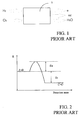
- The operation mechanism of a fuel cell is based on a chemical reaction, wherein the elements at stake are a fuel and a comburent. The fuel can be hydrogen, methanol or other, while the comburent is oxygen. From this chemical reaction electricity, heat and water originate, as schematically shown in Figure 1.
- In particular, in this figure a
fuel cell 1 is schematised which is supplied with hydrogen (H2) and oxygen (O2) and which produces electric energy (in particular electrons e-), water (H2O) and heat (cal). - The energetic profile of a generic chemical reaction can be represented by the following diagram:

- In general, in order for two substances (A+B) to react and give reaction products (C+D) it is necessary that these reactants impact against each other. Not all the impacts between reactants are reactive, but to the purposes of the obtainment of the products and from an energetic point of view only those occurring between molecules having a higher or equal energy with respect to an activation energy Ea are useful. The activation speed of a reaction is thus linked to the number of molecules having a higher or equal energy E with respect to the activation energy Ea (E ≥ Ea), as schematically shown in Figure 2, where the energy E is indicated as a function of the reaction state, as well as a portion of energy Er released by the reaction itself. If the probability of having molecules with enough energy is low, then the reaction will proceed slowly, vice versa if the number of molecules is high.
- It is possible to act on the activation speed by increasing the temperature of the reactants or by lowering the activation energy Ea by using catalysts, as it usually occurs in the use of fuel cell.
- Notwithstanding the adoption of these measures, the attainment of the complete functionality of the fuel cells, is not, however, instantaneous; in particular, when a fuel cell is supplied with a fuel, the production of electricity is not immediate, but it effectively starts after a certain delay commonly indicated as "start-up" time.
- In general, "start-up" indicates the time interval lapsing between the introduction of the fuel into a fuel cell and the stabilisation of its static characteristic I-V.
- The use is also widespread of micro fuel cells as portable supply sources for low power electronic devices. A central membrane coated on both sides by a catalyst layer is the core of a micro fuel cell; across the membrane the reaction occurs with the fuel on one side and with the oxygen present in the air on the other side and they can be realised with techniques known in the field of the microelectronics with extremely reduced dimensions.
- In this case, among the factors influencing the start-up time there are also the moisturizing of the membrane, the diffusion time of the gases through a so called "gas diffusion layer", and others more.
- Micro fuel cells are normally organised in stack structures, where the cells are substantially overlapped on one another.
- Considering the case of a stack of three micro fuel cells supplied with hydrogen, the progress of the open circuit voltage obtained across it during the start-up phase has a typical profile of the type shown in Figure 3A, the stack of micro fuel cells reaching the steady state after a period equal to about 40s.
- Moreover, it is known that a stack of micro fuel cells shows a I-V (current-voltage) characteristic which is static - i.e. relative to all the possible working points of the stack - and stabilised - i.e. once the full operation condition has been reached - of the type shown in Figure 3B. In particular, three operation areas are distinguished: an activation biasing region (A1), an ohmic region (A2), and a concentration biasing region (A3).
- It is thus easily understood that, if a load is connected to a stack of micro fuel cells before the end of the start-up time, the time necessary for the micro fuel cells to reach their optimal operation condition increases and, at least initially, the stack cannot operate at the maximum of its potentiality.
- In other words, the connection of a load to a stack of micro fuel cells before the start-up phase has been completed causes, as a matter-of-fact, the operation of the stack below its potentiality. The delicacy and the importance that this step holds are thus evident so as to operate with a perfectly stabilised stack of micro fuel cells.
- To overcome this drawback, the solutions of the prior art being currently used in the field provide the use of power generators with functions of backup or emergency elements. In particular, systems for supplying micro fuel cells are known comprising at least one precharged buffer battery able to supply a load connected to the micro fuel cell, or the stack of micro fuel cells, during the start-up period, with enough power to allow a connection also in this initial operation phase of the micro fuel cells.
- These supply systems comprising a buffer battery thus provide a connection of this latter to the load up to the completion of the stack start-up phase. The buffer battery supplies, in addition, the energy necessary to supply a control circuit supervising the start-up phase so as to connect the load to the stack only once it is stabilised.
- Although advantageous under several points of view, these known solutions show several drawbacks. In particular, it is immediately evident that these supply systems are not able to manage a start-up phase of a stack of micro fuel cells in case this buffer battery is down as well.
- The technical problem underlying the present invention is that of providing a system for managing the power up step of at least one micro fuel cell, having such structural and functional characteristics as to allow to overcome the limits and drawbacks still affecting the systems realised according to the prior art.
- The solution idea underlying the present invention is that of maintaining the micro fuel cells in an open circuit state until their activation or start-up phase has been ended by inserting, between at least one micro fuel cell and a load which must be driven thereby, a circuit for managing the start-up phase essentially acting as a controlled switch and connecting the micro fuel cell to the load only after this micro fuel cell has ended its start-up phase, indeed.
- On the basis of this solution idea the technical problem is solved by a managing method of the start-up phase of at least one micro fuel cell of the type as previously indicated and defined by the characterising part of
claim 1. - The problem is also solved by a managing circuit of the start-up phase of at least one micro fuel cell of the type as previously indicated and defined by the characterising part of
claim 6. - The characteristics and the advantages of the managing method and circuit of the start-up phase of at least one micro fuel cell according to the invention will be apparent from the following description of embodiments thereof given by way of indicative and non limiting example with reference to the annexed drawings.
- In these drawings:
- Figure 1 shows a functional scheme of a fuel cell supplied with hydrogen according to the prior art;
- Figure 2 shows an energetic diagram of a generic exothermic chemical reaction;
- Figures 3A to 3B show the progress of inner signals relative to a stack of micro fuel cells realised according to the prior art;
- Figures 4A and 4B schematically show the operation principle of a managing circuit of the start-up phase of at least one micro fuel cell realised according to the invention;
- Figure 5 schematically shows a voltage-current or V-I characteristic of a stack of micro fuel cells under static conditions and the relative power curve;
- Figure 6 schematically shows a managing circuit of the start-up phase of at least one micro fuel cell realised according to the invention;
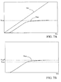
- Figures 7A and 7B show the progress of inner signals of the managing circuit according to the invention;
- Figures 8A-8C show the progress of inner signals of the managing circuit according to the invention under different operative conditions of the same;
- Figures 9A and 9B show values of the current absorbed by the managing circuit according to the invention under different operative conditions of the same;
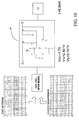
- Figure 10 shows a configuration set-up used to simulate the operation of the managing circuit according to the invention;
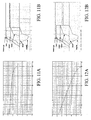
- Figures 11A-11B and 12A-12B show the results of simulations carried out on the managing circuit according to the invention;
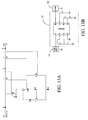
- Figures 13A-13B show a possible integration of the managing circuit according to the invention.
- With reference to these figures, a circuit is described for managing the start-up phase of at least one micro fuel cell realised according to the invention, globally and schematically indicated with 10.
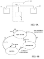
- In particular, as shown in Figure 4A, the managing
circuit 10 according to the invention is inserted between at least one micro fuel cell, preferably astack 11 of micro fuel cells, and aload 12 and it essentially comprises a switch SW driven by acontrol portion 13. - Advantageously according to the invention, the managing
circuit 10 implements a method for managing the start-up phase of at least one micro fuel cell, preferably astack 11 of micro fuel cells comprising the steps of: - measuring a voltage value across the
stack 11 of micro fuel cells, hereafter indicated as stack voltage VFC, thestack 11 being activated through fuel injection; - comparing this stack voltage VFC with a first predetermined threshold voltage value, hereafter indicated as ignition or turn-on threshold VTH; and
- stabilising an operation mode of the
stack 11 of micro fuel cells according to the following conditions:- as long as the stack voltage VFC is lower than the ignition threshold VTH (VFC<VTH), the
stack 11 of micro fuel cells operates in a first "open circuit" state, during which it is not connected to the load 12 (loadless operation); - when the stack voltage VFC overcomes the ignition threshold VTH (VFC>VTH), the
stack 11 of micro fuel cells passes to a second "pre-ignition" state, during which thestack 11 of micro fuel cells supplies a current value IFC corresponding to the ignition threshold VTH, according to a static voltage current or V-I characteristic of thestack 11 of micro fuel cells.
- as long as the stack voltage VFC is lower than the ignition threshold VTH (VFC<VTH), the
- The managing method of the start-up phase according to the invention thus provides the steps of:
- measuring a current value IFC as supplied by the
stack 11 of micro fuel cells; and - modifying the operation of the
stack 11 of micro fuel cells according to the following characteristics:- if the
stack 11 of micro fuel cells is not able to supply a current required by theload 12, return into the first open circuit state; - if the
stack 11 of micro fuel cells succeeds in supplying the current required by theload 12, passage to a third "ignition" state.
- if the
- The managing method of the start-up phase according to the invention finally provides a step of return to the first open circuit state when the stack voltage VFC decreases below a second threshold voltage value, hereafter indicated as shut down threshold VTL.
- Advantageously, when the
stack 11 of micro fuel cells is in the first open circuit operation mode, the managingcircuit 10 does not allow its connection to theload 12. Once the stack voltage VFC overcomes the ignition threshold VTH, thestack 11 of micro fuel cells is requested to supply a value of current IFC corresponding to the ignition threshold VTH, according to the static V-I characteristic of thestack 11 of micro fuel cells. - In particular, the ignition threshold VTH is chosen so that it is next to a predetermined loadless voltage of the
stack 11 of micro fuel cells corresponding to the end of the start-up phase, i.e. to a stabilised condition of the stack. - At this point, if the
stack 11 of micro fuel cells does not succeeds in supplying the current IFC required, there is a return to the first open circuit state; vice versa, there is a passage to the third ignition state. - The
stack 11 of micro fuel cells remains in this third ignition state until, once the fuel is exhausted, the stack voltage VFC decreases below the shut down threshold VTH. - When this occurs, the
stack 11 of micro fuel cells returns to the first "open circuit" state. - The operation principle of the managing
circuit 10 according to the method of the invention is shown by means of a state diagram in Figure 4B. - In particular, in this Figure 4B the first open circuit state, the second pre-ignition state and the third ignition state of a
stack 11 of micro fuel cells are shown, respectively indicated with S1, S2 and S3, connected to each other by connections C1, C2, C3, C4, C5 and C6 corresponding to the conditions of the above indicated steps of the method. - In particular, as above explained, the
stack 11 of micro fuel cells is maintained in the first opencircuit state S 1 until the condition VFC<VTH (connection C1) turns out and passes to the second pre-ignition state S2 when the stack voltage VFC overcomes the ignition threshold VTH, i.e. the condition VFC>VTH (connection C2) is verified. - At this point, the characteristic of the
stack 11 of micro fuel cells is verified by measuring the current IFC supplied and two state passages are possible: - if the
stack 11 of micro fuel cells does not succeeds in supplying the current IFC required, i.e. in case of a non-stabilised characteristic, thestack 11 of micro fuel cells returns into the first open circuit state S1 (connection C3); - if the
stack 11 of micro fuel cells succeeds in supplying the current IFC required, i.e. in case of a stabilised characteristic, thestack 11 of micro fuel cells passes to the third ignition state S3 (connection C4). - The
stack 11 of micro fuel cells remains in the third ignition state S3 until the condition VFC>VTL (connection C5) is verified and returns into the first open circuit state S1 when the stack voltage VFC decreases below the shut down threshold VTL, i.e. the relation VFC<VTL (connection C6) is verified. - Figure 5 shows an approximated stabilised static V-I characteristic typical of a stack of micro fuel cells, globally indicated with CIV, where also the real characteristic (CIVr) and its detachment from an ideal condition in correspondence with the extreme values of this characteristic are indicated with broken lines.
- Figure 5 again indicates the ignition VTH and the shut down VTL threshold values and the corresponding values of supplied current, as well as a pre-selected working point PL in case of staying in the third ignition state S3, to which working current and voltage values, indicated with VL and IL respectively, as well as the power curve of such a stack of micro fuel cells, indicated with PWfc, correspond.
- Advantageously according to the invention, the method for managing the start-up phase as just described is implemented by a managing
circuit 10 interposed between astack 11 of micro fuel cells and aload 12, this managingcircuit 10 essentially acting as a driven switch. An embodiment of the managingcircuit 10 according to the invention is schematically shown in Figure 6. - In particular, the managing
circuit 10 has an input terminal IN connected to astack 11 of micro fuel cells and an output terminal OUT connected to aload 12 and comprises at least one first enableblock 14 inserted between the input terminal IN and the output terminal OUT of the managingcircuit 10 and having at least one control terminal connected to an output terminal O* of agenerator block 20 comprised in the managingcircuit 10. In particular, at the output terminal O* of this generator block 20 a reference voltage signal VREF is generated. - Advantageously, the managing
circuit 10 further comprises a second enable block 15 inserted, in series to the first enableblock 14, between the input terminal IN and the output terminal OUT of the managingcircuit 10 and having at least one control terminal connected to the output terminal O* of thegenerator block 20. - In the example of Figure 6, these first and second enable block, 14 and 15, essentially comprise a first M1 and a second transistor M2 inserted, in series to each other, between the input terminal IN and the output terminal OUT of the managing
circuit 10 and having respective control terminals connected to the output terminal O* of thegenerator block 20 of an inner voltage reference. - The managing
circuit 10 also comprises afirst control block 16 inserted between the input terminal IN and a first inner circuit node X1 of interconnection between thisfirst control block 16 and thegenerator block 20. In particular, in the example shown in Figure 6, thefirst control block 16 comprises a first control transistor M3 inserted between the input terminal IN and the first inner circuit node X1 and having a control terminal connected to a second inner circuit node X2 of interconnection between the first 14 and thesecond biasing block 15. - The managing
circuit 10 further comprises asecond control block 17, inserted between the output terminal O* of thegenerator block 20 and a voltage reference, in particular a ground GND. In particular, in the example shown in Figure 6, thesecond control block 17 comprises in turn a second control transistor M4 inserted between the output terminal O* of thegenerator block 20 and the ground GND and having a control terminal connected to the output terminal OUT of the managingcircuit 10. - The managing
circuit 10 finally comprises a pre-ignition capacitor Cb1, inserted between the second inner circuit node X2 and the ground GND. - In the example shown in Figure 6, the
generator block 20 comprises a first bipolar transistor Q1, as well as a first R1 and a second resistor R2 inserted, in series to each other between the first inner circuit node X1 and the ground GND. Thegenerator block 20 further comprises a third resistor R3 and a second bipolar transistor Q2 also inserted, in series to each other, between the first inner circuit node X1 and the ground GND. - In particular, the first bipolar transistor Q1 is inserted between the first inner circuit node X1 and the output terminal O* of the
generator block 20 and has a control terminal connected to a third inner circuit node X3 of interconnection between the third resistor R3 and the second bipolar transistor Q2, in turn inserted between this third inner circuit node X3 and the ground GND and having a control terminal connected to a fourth inner circuit node X4 of interconnection between the first R1 and the second resistor R2. - Finally, the
generator block 20 comprises a filtering capacitor Cb2 inserted between the third inner circuit node X3 and the ground GND. - Advantageously according to the invention, the bipolar transistors Q1 and Q2 and the resistors R1, R2 and R3 realise a generator of the reference voltage VREF while the third resistor R3 and the filtering capacitor Cb2 realise a low-pass filter for the noises coming from the
stack 11 of micro fuel cells connected to the input terminal IN of the managingcircuit 10. - Let's now see the operation of the managing
circuit 10 according to the invention. - The first and second transistors, M1 and M2, of the first and second enable blocks, 14 and 15, are substantially switches enabled to the passage from the first open circuit state S1 to the second pre-ignition circuit state S2 and from the second pre-ignition state S2 to the third ignition state S3, while the pre-ignition capacitor Cb1 supervises the second pre-ignition state S2.
- In particular, the first transistor M1 of the first enable
block 14 is enabled in the passage from the first open circuit state S1 to the second pre-ignition state S2. Thisfirst transistor M 1 is powered-on in a sub-threshold state and charges the pre-ignition capacitor Cb1 with a sub-threshold current of limited value, drawn from thestack 11 of micro fuel cells. In this way, advantageously according to the invention, the managingcircuit 10 absorbs an irrelevant current value with respect to a current potentially supplied by thestack 11 of micro fuel cells and, advantageously according to the invention, does not require an external supply battery. - Moreover, by acting on the value of the pre-ignition capacitor Cb1 one can intervene on the duration of the staying time of the managing
circuit 10 in the second pre-ignition state S2. - The ignition of the second transistor M2 of the second enable
block 15 brings the voltage value onto the output terminal O* to the ground GND and connects the input terminal IN to the output terminal OUT of the managingcircuit 10. This second transistor M2 is enabled in the passage from the second pre-ignition state S2 to the third ignition state S3 and enables the connection of thestack 11 of micro fuel cells to theload 12. - In particular, the sum of the threshold voltage values of these first and second enable transistors, M1 and M2, fix the shut down threshold value VTL, used for the shut-down of the managing
circuit 10. - It is to be noted that the presence of this ignition threshold VTL allows to maintain the operation level of the
stack 11 of micro fuel cells slightly below its maximum performances and can be used for indicating the approaching of the exhausting of the fuel of the stack itself. - To understand the operation of the managing
circuit 10 it is to be specified that the first open circuit state S1 essentially comprises two operation sub-steps of the managingcircuit 10. - In particular, at the beginning of the start-up phase of the
stack 11 of micro fuel cells, the stack voltage VFC applied to the input terminal IN of the managingcircuit 10 is null (VFC=0). Under these conditions, all the current and voltage values of the managingcircuit 10 are null. - As long as the stack voltage VFC remains below a threshold voltage value VTM3 of the first control transistor M3 of the first control block 16 (VFC<VTM3), the transistors M1, M2, M3 and M4 are off and the
generator block 20 which generates the reference voltage signal VREF is disconnected. - When the stack voltage VFC equals or overcomes the threshold voltage value VTM3 of the first control transistor M3 of the first control block 16 (VFC≥VTM3), the first control transistor M3 is powered-on and connects the
generator block 20 to the input terminal IN of the managingcircuit 10 whereat there is the stack voltage VFC. - By further increasing this stack voltage VFC at the input terminal IN, the voltage value at the output terminal O* of the
generator block 20, corresponding to the voltage VEQ1 of the emitter terminal of the first bipolar transistor Q1, grows in turn, following the same profile as the stack voltage VFC - unless a voltage drop occurs equal to the sum of the voltage between base and emitter of the first bipolar transistor Q1 (VBE1) and the voltage between source and drain of the first control transistor M3 (VSDM3) - until a limit value VLIM is reached corresponding to a limit value of the reference voltage signal VREF, as shown in Figure 7A, which reports the progress of the stack voltage VFC and of the voltage VEQ1 of the emitter terminal of the first bipolar transistor Q1. - If the stack voltage VFC further grows until it takes a value equal to the ignition threshold VTH, given by the sum of the limit value VLIM and of the threshold voltage value VTM1 of the first control transistor M1 of the first control block 16 (VFC=VLIM+VTM1=VTH), this first
control transistor M 1 is powered on switching the operation mode of the managingcircuit 10 in the second pre-ignition state S2. - In other words, the first open circuit state S1 comprises the following two sub-steps:
- VFC<VTM3
- M1, M2, M3 and M4 are off and the
generator block 20 is disconnected - VTM3<VFC<VLIM+VTM1
- M3 is on, the voltage VEQ1 at the emitter of Q1 grows following the profile of the input voltage equal to the stack voltage VFC until the limit value VLIM is attained
- In the second pre-ignition state S2, the ignition threshold VTH being fixed at the limits of a voltage value expected for an open circuit operation mode for the
stack 11 of micro fuel cells, the first control transistor M1 is in the "sub-threshold" operation region. The current ID flowing through this transistor is given by:
- VSG and VSD the voltage values between source and gate and between source and drain, respectively, of the transistor M1;
- I0 a technological parameter linked to the realisation of the transistor M1; and
-

- Being VSD > 0 and


M1 | the following is obtained:
- It is thus easily obtained that the second pre-ignition state S2 remains active for a time equal to:

- Moreover, the passage from the second pre-ignition state S2 to the third ignition state S3 immediately occurs when the following relation is verified:

- In fact, as soon as the above reported relation (5) turns out, the first control transistor M3 starts to shut down, and the reference voltage signal VREF generated by the
generator block 20 decreases allowing a full power-on of the first transistor M1 of the first enableblock 14 and thus of the second transistor M2 of the second enableblock 15. As soon as a voltage signal VOUT at the output terminal OUT of the managingcircuit 10 reaches a threshold voltage value VTM4 of the second control transistor M4, this transistor is powered on, bringing the reference voltage signal VREF at the output terminal O* to a value next to zero. - The decrease of the reference voltage signal VREF and the power-on of the second control transistor M4 cause matterly-of-fact a variation of the shut down threshold value of the enable transistors M1 and M2. In fact, in the second pre-ignition state S2 this shut down threshold is equal to the ignition threshold VTH, i.e.:


- As previously seen, the managing
circuit 10 remains in the third ignition state S3 until the exhaust of the fuel of thestack 11 of micro fuel cells causes a decrease of the stack voltage VFC below the shut down threshold VTL. - It is also to be specified that, neglecting the voltage variation between base and emitter VBE1 of the first bipolar transistor Q1 due to the temperature, a theoretical limit value VLIM* is obtained for the reference voltage signal VREF equal to:

- In a practical case, however, the limit value of the reference voltage signal VREF to be considered for the purposes of the activation of the first enable transistor M1 is next to a "knee", as shown in Figure 7B. The above reported equation (8) is thus to be modified with the introduction of a suitable correction factor (equal to 0.85), obtaining:

- Advantageously, the values of the resistors R1, R2 and R3 comprised in the
generator block 20 are dimensioned taking into account the currents absorbed by the managingcircuit 10. In particular considering:
- I being the current absorbed by the
generator block 20, I3 the current in the first resistor R1 and I1-2 the current flowing through the series of the first R1 and of the second resistor R2; neglecting the source-drain voltage VSDM3 of the first control transistor M3 and the base current of thebipolar transistors Q 1 and Q2, what follows is obtained:


- Moreover, considering that the third resistor R3 and the filtering capacitor Cb2 realise a low-
pass filter 19 of the noises of the stack voltage VFC in the first open circuit state S1 and in the second pre-ignition state S2 having a cut-off frequency fT, the value of the filtering capacitor Cb2 is advantageously determined with the following relation:
- Finally, the value of the pre-ignition capacitor Cb1 is established on the basis of the dynamics of the
stack 11 of micro fuel cells as considered and of the duration which is to be obtained for the staying of the managingcircuit 10 in the second pre-ignition state S2. - It is further possible to determine the form ratios of the enable transistors M1 and M2 according to the desired values of ignition resistances RDSON; taking into account that in the ignition state these transistors are in triode region the following is obtained:

- The managing
circuit 10 proposed has been simulated by the Applicant, the results of this simulation being shown in Figures 8A-8C under the following conditions: - the values of the resistors R1, R2 and R3 have been chosen so that a limit value VLIM = 1.7V was fixed;
- the values of the capacitors have been set equal to CB1= 47uF and Cb2= 10pF; and
- the MOS transistors have been realised with minimum channel length equal to 1.2um and with threshold voltages given by:


- VTP and VTN being the threshold voltage values of the MOS transistors with P and N channel, respectively
- Thus, by using the above reported equations (6) and (7), ignition threshold VTH and shut down threshold VTL values are obtained equal to:


- Figure 8A shows the results obtained by varying the stack voltage VFC, corresponding to an input voltage value VIN of the managing
circuit 10 in a linear way from 0V up to 3V. In particular the progress is indicated of the signal VOUT at the output terminal OUT of the managingcircuit 10 and the progress of the voltage VEQ1 at the emitter of the first bipolar transistor Q1 until the limit voltage value VLIM is obtained. - Figure 8B shows the results of an analysis in DC of the managing
circuit 10 obtained by varying the input voltage VIN in a linear way from 3V up to 0V. Also in this case, in particular, the progress is indicated of the signal VOUT on the output terminal OUT of the managingcircuit 10 and the progress of the voltage VEQ1 on the emitter of the first bipolar transistor Q1. - Similarly, Figure 8C shows the response of the managing
circuit 10 when, to its input terminal IN, a voltage signal VIN is applied which varies in time with a trapezoidal profile. In particular, the input voltage VIN takes 300s in the passage from 0V up to 3V, and, symmetrically, in the passage from 3V up to 0V. In this Figure 8C the progresses are shown of the input signal VIN, of the output signal VOUT and of the voltage VEQ1 at the emitter of the first bipolar transistor Q1. - The current absorbed by the managing
circuit 10 as a function of the input voltage VIN has also been evaluated, in particular in the first open circuit state S1 and in the second pre-ignition state S2, as shown in Figures 9A and 9B respectively. - It has thus been verified that the maximum value of absorbed current is equal to about 5uA.
- The Applicant has then simulated the responses of the managing
circuit 10 when the static I-V characteristic of thestack 11 of micro fuel cells connected thereto varies, by applying, at the input, a typical start-up profile as the one shown in Figure 3A. The simulations have been carried out by connecting, at the input of the managingcircuit 10 proposed, a spice model of astack 11 of micro fuel cells and, at the output, aload 12 of the resistive type of 233Ω, as schematically indicated in Figure 10. - In particular, the simulations have been repeated when the static I-V characteristic of the
stack 11 of micro fuel cells varied. The results of these simulations - carried out with the voltage profiles indicated in Figures 11A and 12A - are shown in Figures 11B and 12B where a typical start-up profile Vstart-up, the stack voltage VFC, the reference voltage signal VREF, the voltage Vcb1 across the pre-ignition capacitor Cb1, the voltage VSGM2 between source and gate of the second enable transistor M2 and the output voltage VOUT are represented. - Advantageously according to the invention, the managing
circuit 10 can be easily integrated. In particular, it is possible to integrate the transistors comprised therein, by connecting, as external components, the resistors R1, R2 and R3 and the capacitors Cb1 and Cb2, by means of suitable PINs, as shown in Figures 13A and 13B, where the portion to be integrated (Figure 13A) and the discrete equivalent of the managingcircuit 10 as proposed (Figure 13B) are shown. - In conclusion, the method and the circuit for managing the start-up phase of a stack of micro fuel cells according to the invention allow to ensure that the stack of micro fuel cells is connected to the load only at the end of its start-up period, i.e. when it is possible to exploit its potentialities at the maximum, its static I-V characteristic having stabilised.
- Advantageously, the method and the circuit for managing the start-up phase according to the invention provide an operation mode of the stack of micro fuel cells in the pre-ignition state, useful for monitoring the start-up profile at best, regulating possible spurious peaks on the start-up current of the stack itself.
- Moreover, by acting on the value of the pre-ignition capacitor Cb1 it is also possible to intervene on the duration of the staying time of the managing
circuit 10 in this pre-ignition state. - The value of the third resistor R3 is linked to the current absorbed by the
generator block 20. Moreover, the values of this third resistor R3 and of the filtering capacitor Cb2 is linked to the cut-off frequency of the low-pass filter 19 realised thereby inside thegenerator block 20. - Furthermore, the managing
circuit 10 as proposed allows to fix the ignition threshold value VTH in an accurate way by dimensioning the resistances R1 and R2 fixing a limit value VLIM* of the driving voltage signal VREF according to the relation:
- VBE2 being the difference of voltage between base and emitter of the second bipolar transistor Q2.
- Advantageously, the managing
circuit 10 according to the invention shows a low power consumption and operates using only a small portion of the energy generated by the stack of micro fuel cells, thus not requiring an external supply battery. - Suitably, a shut down threshold VTL is also provided for the disconnection of the load when the stack of micro fuel cells has ended the fuel.
- Finally, it is to be noted that the managing
circuit 10 although absorbing a small current from the stack of micro fuel cells can be used as evidence of the operation of the stack itself. - The managing
circuit 10 according to the invention can thus be used also in applications wherein possible buffer batteries already present can be completely down thus overcoming the limitations of the known supply systems and allowing to manage the start-up phase of the stack of micro fuel cells independently from the presence of a charge buffer battery.
Claims (21)
- Managing method of the start-up phase of at least one micro fuel cell (11) to be connected to a load (12) comprising the steps of:- measuring a micro fuel cell voltage value (VFC) across said at least one micro fuel cell (11) activated by means of a fuel injection;said method being characterised in that it further comprises the steps of:- comparing said micro fuel cell voltage value (VFC) with a first predetermined threshold voltage value (VTH); and- establishing an operation mode of said at least one micro fuel cell (11) according to the following conditions:- as long as said micro fuel cell voltage value (VFC) is lower than said first threshold voltage value (VTH), said at least one micro fuel cell (11) operates in a first open circuit state (S1), during which it is not connected to said load (12);- when said micro fuel cell voltage value (VFC) overcomes said first threshold voltage value (VTH), said at least one micro fuel cell (11) passes to a second pre-ignition state (S2), during which it supplies a current value (IFC) corresponding to said first threshold voltage value (VTH), according to a static voltage-current or V-I characteristic of said at least one micro fuel cell (11).
- Managing method according to claim 1, characterised in that it further comprises the steps of:- measuring a value (IFC) of current supplied by said at least one micro fuel cell (11) ; and- modifying said operation mode of said at least one micro fuel cell (11) according to the following conditions:- if said at least one micro fuel cell (11) does not succeed in supplying a current value as required by said load (12), return into said first open circuit state (S1);- if said at least one micro fuel cell (11) succeeds in supplying said required current value, passage to a third ignition state (S3).
- Managing method according to claim 1, characterised in that it further comprises a return step to said open circuit state (S1) when said micro fuel cell voltage value (VFC) decreases below a predetermined second threshold voltage value (VTL).
- Managing method according to claim 1, characterised in that said first threshold voltage value (VTH) is chosen so that it is next to a predetermined loadless voltage of said at least one micro fuel cell (11) corresponding to the end of the start-up phase of said at least one micro fuel cell (11).
- Managing method according to any one of the preceding claims, characterised in that it manages a start-up phase in a stack of micro fuel cells (11) to be connected to said load (12).
- Managing circuit (10) of the start-up phase of at least one micro fuel cell (11) to be connected to a load (12), said managing circuit (10) being characterised in that it has an input terminal (IN) connected to said at least one micro fuel cell (11) and an output terminal (OUT) connected to said load (12) and in that it comprises at least a first enable block (14) inserted between said input and output terminals (IN, OUT) and having at least one control terminal connected to an output terminal (O*) of a generator block (20) of a reference voltage signal (VREF) comprised in said managing circuit (10).
- Managing circuit (10) according to claim 6, characterised in that it further comprises at least a second enable block (15) inserted, in series to said first enable block (14), between said input and output terminals (IN, OUT) and having at least one control terminal connected to said output terminal (O*) of said generator block (20).
- Managing circuit (10) according to claim 7, characterised in that said first and second enable blocks (14, 15) comprise respective first and second enable transistors (M1, M2) having respective conduction terminals connected, in series to each other, between said input and output terminals (IN, OUT) and respective control terminals connected to said output terminal (O*) of said generator block (20).
- Managing circuit (10) according to claim 8, characterised in that said first and second enable transistors (M1, M2) are transistors of the MOS type.
- Managing circuit (10) according to claim 6, characterised in that said generator block (20) is inserted between a first inner circuit node (X1) and a voltage reference (GND) and it comprises at least one first transistor (Q1) as well as a first and a second resistor (R1, R2) inserted, in series to each other, between said first inner circuit node (X1) and said voltage reference (GND), said first transistor (Q1) being inserted between said first inner circuit node (X1) and said output terminal (O*) of said generator block (20).
- Managing circuit (10) according to claim 10, characterised in that said generator block (20) further comprises a third resistor (R3) and a second transistor (Q2) also inserted, in series to each other, between said first inner circuit node (X1) and said voltage reference (GND) and defining together a first interconnection node (X3) connected to a control terminal of said first transistor (Q1).
- Managing circuit (10) according to claim 11, characterised in that said second transistor (Q2) has a control terminal connected to a second interconnection node (X4) defined by said first and second resistors (R1, R2).
- Managing circuit (10) according to claim 11, characterised in that said generator block (20) further comprises a filtering capacitor (Cb2) inserted, in parallel to said second transistor (Q2) between said first interconnection node (X3) and said voltage reference (GND), said third resistor (R3) and said filtering capacitor (Cb2) realising a low-pass filter (19) of said generator block (20).
- Managing circuit (10) according to claim 10, characterised in that it further comprises a first control block (16) inserted between said input terminal (IN) and said first inner circuit node (X1) and having a control terminal connected to a second inner circuit node (X2) defined by the interconnection of said first and second enable blocks (14, 15).
- Managing circuit (10) according to claim 14, characterised in that said first control block (16) comprises a first control transistor (M3) having conduction terminals connected to said input terminal (X1) and to said first inner circuit node (X1) and a control terminal connected to said second inner circuit node (X2).
- Managing circuit (10) according to claim 10, characterised in that it further comprises a second control block (17) inserted between said output terminal (O*) of said generator block (20) and said voltage reference (GND) and having a control terminal connected to said output terminal (OUT) of said managing circuit (10).
- Managing circuit (10) according to claim 16, characterised in that said second control block (17) comprises a second control transistor (M4) having conduction terminals connected to said output terminal (O*) of said generator block (20) and to said voltage reference (GND) and a control terminal connected to said output terminal (OUT) of said managing circuit (10).
- Managing circuit (10) according to claim 5, characterised in that it further comprises a pre-ignition capacitor (Cb1) inserted between an inner circuit node (X2) defined by the interconnection of said first and second enable blocks (14, 15) and a voltage reference (GND).
- Managing circuit (10) according to claim 11, characterised in that said first and second transistors (Q1, Q2) of said generator block (20) are bipolar transistors.
- Managing circuit (10) according to claim 15 or 17, characterised in that said first and second control transistors (M3, M4) are MOS transistors.
- Managing circuit (10) according to any of the claim 6 to 20, characterised in that said input terminal (IN) is connected to a stack of micro fuel cells (11) to be connected to said load (12).
Priority Applications (3)
| Application Number | Priority Date | Filing Date | Title |
|---|---|---|---|
| EP20060425242 EP1843422B1 (en) | 2006-04-06 | 2006-04-06 | Method and circuit for managing a start-up phase of at least a micro fuel cell to be connected to a load |
| DE200660018259 DE602006018259D1 (en) | 2006-04-06 | 2006-04-06 | Method and circuit for controlling the startup of a micro fuel cell |
| US11/697,153 US7906874B2 (en) | 2006-04-06 | 2007-04-05 | Method and circuit for managing start-up phase of at least a micro fuel cell to be connected to a load |
Applications Claiming Priority (1)
| Application Number | Priority Date | Filing Date | Title |
|---|---|---|---|
| EP20060425242 EP1843422B1 (en) | 2006-04-06 | 2006-04-06 | Method and circuit for managing a start-up phase of at least a micro fuel cell to be connected to a load |
Publications (2)
| Publication Number | Publication Date |
|---|---|
| EP1843422A1 true EP1843422A1 (en) | 2007-10-10 |
| EP1843422B1 EP1843422B1 (en) | 2010-11-17 |
Family
ID=37441037
Family Applications (1)
| Application Number | Title | Priority Date | Filing Date |
|---|---|---|---|
| EP20060425242 Expired - Lifetime EP1843422B1 (en) | 2006-04-06 | 2006-04-06 | Method and circuit for managing a start-up phase of at least a micro fuel cell to be connected to a load |
Country Status (3)
| Country | Link |
|---|---|
| US (1) | US7906874B2 (en) |
| EP (1) | EP1843422B1 (en) |
| DE (1) | DE602006018259D1 (en) |
Cited By (1)
| Publication number | Priority date | Publication date | Assignee | Title |
|---|---|---|---|---|
| WO2015122097A1 (en) * | 2014-02-17 | 2015-08-20 | 日産自動車株式会社 | Fuel cell system and control method for fuel cell system |
Families Citing this family (2)
| Publication number | Priority date | Publication date | Assignee | Title |
|---|---|---|---|---|
| WO2009040112A2 (en) * | 2007-09-25 | 2009-04-02 | Eads Deutschland Gmbh | Method for operating a gas turbine engine, power supplying device for conducting such method and aircraft using such method |
| US8986899B2 (en) * | 2012-10-29 | 2015-03-24 | Gm Global Technology Operations, Llc | Systems and methods for enhancing fuel cell vehicle startup |
Citations (6)
| Publication number | Priority date | Publication date | Assignee | Title |
|---|---|---|---|---|
| JPH01154469A (en) * | 1987-12-10 | 1989-06-16 | Fuji Electric Co Ltd | Automatic start-up-control method for fuel cell |
| EP1233468A2 (en) * | 2001-02-15 | 2002-08-21 | Delphi Technologies, Inc. | A fuel cell and battery voltage controlling method in a hybrid fuel cell/battery system |
| US20030022031A1 (en) | 2001-07-25 | 2003-01-30 | Ballard Power Systems Inc. | Fuel cell system automatic power switching method and apparatus |
| US20030207162A1 (en) * | 2002-05-01 | 2003-11-06 | Reiser Carl A. | Battery-Boosted, rapid startup of frozen fuel cell |
| EP1471588A1 (en) * | 2002-01-29 | 2004-10-27 | Matsushita Electric Industrial Co., Ltd. | Semiconductor device having fuel cell and its manufacturing method |
| EP1638159A2 (en) * | 2004-09-16 | 2006-03-22 | Seiko Instruments Inc. | Fuel cell system |
-
2006
- 2006-04-06 DE DE200660018259 patent/DE602006018259D1/en not_active Expired - Lifetime
- 2006-04-06 EP EP20060425242 patent/EP1843422B1/en not_active Expired - Lifetime
-
2007
- 2007-04-05 US US11/697,153 patent/US7906874B2/en not_active Expired - Fee Related
Patent Citations (6)
| Publication number | Priority date | Publication date | Assignee | Title |
|---|---|---|---|---|
| JPH01154469A (en) * | 1987-12-10 | 1989-06-16 | Fuji Electric Co Ltd | Automatic start-up-control method for fuel cell |
| EP1233468A2 (en) * | 2001-02-15 | 2002-08-21 | Delphi Technologies, Inc. | A fuel cell and battery voltage controlling method in a hybrid fuel cell/battery system |
| US20030022031A1 (en) | 2001-07-25 | 2003-01-30 | Ballard Power Systems Inc. | Fuel cell system automatic power switching method and apparatus |
| EP1471588A1 (en) * | 2002-01-29 | 2004-10-27 | Matsushita Electric Industrial Co., Ltd. | Semiconductor device having fuel cell and its manufacturing method |
| US20030207162A1 (en) * | 2002-05-01 | 2003-11-06 | Reiser Carl A. | Battery-Boosted, rapid startup of frozen fuel cell |
| EP1638159A2 (en) * | 2004-09-16 | 2006-03-22 | Seiko Instruments Inc. | Fuel cell system |
Cited By (1)
| Publication number | Priority date | Publication date | Assignee | Title |
|---|---|---|---|---|
| WO2015122097A1 (en) * | 2014-02-17 | 2015-08-20 | 日産自動車株式会社 | Fuel cell system and control method for fuel cell system |
Also Published As
| Publication number | Publication date |
|---|---|
| DE602006018259D1 (en) | 2010-12-30 |
| US20070237992A1 (en) | 2007-10-11 |
| US7906874B2 (en) | 2011-03-15 |
| EP1843422B1 (en) | 2010-11-17 |
Similar Documents
| Publication | Publication Date | Title |
|---|---|---|
| Xiao et al. | A modified adaptive hill climbing MPPT method for photovoltaic power systems | |
| EP2806531B1 (en) | Booster | |
| US8362748B2 (en) | Voltage comparison circuit | |
| TWI354197B (en) | Device and method for controlling current limits w | |
| CN1738087B (en) | Power supply device and control method thereof | |
| US9897663B2 (en) | Integrated DC/DC converter, electrochemical energy storage system, and methods for analyzing electrochemical impedance spectroscopy and working state of electrochemical energy storage apparatus | |
| US6828764B2 (en) | Regulator circuit and control method thereof | |
| US20110068817A1 (en) | Solar cell output characteristic evaluation apparatus and solar cell output characteristic evaluation method | |
| CN101097456B (en) | Voltage regulator | |
| RU2000128660A (en) | FUEL ELEMENT SYSTEM AND METHOD FOR FUEL ELEMENT MANAGEMENT | |
| CN101165958A (en) | Fuel cell system and method of operating the same | |
| CN102119460B (en) | Fuel cell system and electronic device | |
| CN101315568A (en) | Reference voltage generator and voltage regulator incorporating same | |
| US7906874B2 (en) | Method and circuit for managing start-up phase of at least a micro fuel cell to be connected to a load | |
| Guilbert et al. | Hydrogen flow rate control of a proton exchange membrane electrolyzer | |
| CN106160419A (en) | Low voltage difference voltage-stabilized power supply circuit structure | |
| JP3220100B2 (en) | Power supply circuit and power supply method | |
| Henni et al. | Design and implementation of a low-cost characterization system for photovoltaic solar panels | |
| JPWO2015045074A1 (en) | Step-down power supply circuit, power supply module, and step-down power supply circuit control method | |
| US7012412B2 (en) | Switching power source circuit capable of turning off an “off” drive circuit before a drive control signal becomes active and an electronic device using the same | |
| US7844434B2 (en) | System and methods for implementing a non-linear electrical circuit dynamic fuel cell model | |
| Jupke et al. | Bidirectional dc-dc converter with digital droop parameterization | |
| US20210211094A1 (en) | Method for driving electronic device | |
| CN107528468A (en) | A kind of high tension charge pump circuit | |
| KR20100098870A (en) | Photovoltaic power generation system, apparatus and method for tracking maximum power point |
Legal Events
| Date | Code | Title | Description |
|---|---|---|---|
| PUAI | Public reference made under article 153(3) epc to a published international application that has entered the european phase |
Free format text: ORIGINAL CODE: 0009012 |
|
| AK | Designated contracting states |
Kind code of ref document: A1 Designated state(s): AT BE BG CH CY CZ DE DK EE ES FI FR GB GR HU IE IS IT LI LT LU LV MC NL PL PT RO SE SI SK TR |
|
| AX | Request for extension of the european patent |
Extension state: AL BA HR MK YU |
|
| 17P | Request for examination filed |
Effective date: 20080410 |
|
| AKX | Designation fees paid |
Designated state(s): DE FR GB IT |
|
| 17Q | First examination report despatched |
Effective date: 20080606 |
|
| RAP1 | Party data changed (applicant data changed or rights of an application transferred) |
Owner name: STMICROELECTRONICS SRL |
|
| GRAP | Despatch of communication of intention to grant a patent |
Free format text: ORIGINAL CODE: EPIDOSNIGR1 |
|
| GRAS | Grant fee paid |
Free format text: ORIGINAL CODE: EPIDOSNIGR3 |
|
| GRAA | (expected) grant |
Free format text: ORIGINAL CODE: 0009210 |
|
| AK | Designated contracting states |
Kind code of ref document: B1 Designated state(s): DE FR GB IT |
|
| REG | Reference to a national code |
Ref country code: GB Ref legal event code: FG4D |
|
| REF | Corresponds to: |
Ref document number: 602006018259 Country of ref document: DE Date of ref document: 20101230 Kind code of ref document: P |
|
| PLBE | No opposition filed within time limit |
Free format text: ORIGINAL CODE: 0009261 |
|
| STAA | Information on the status of an ep patent application or granted ep patent |
Free format text: STATUS: NO OPPOSITION FILED WITHIN TIME LIMIT |
|
| 26N | No opposition filed |
Effective date: 20110818 |
|
| REG | Reference to a national code |
Ref country code: DE Ref legal event code: R097 Ref document number: 602006018259 Country of ref document: DE Effective date: 20110818 |
|
| GBPC | Gb: european patent ceased through non-payment of renewal fee |
Effective date: 20110406 |
|
| PG25 | Lapsed in a contracting state [announced via postgrant information from national office to epo] |
Ref country code: DE Free format text: LAPSE BECAUSE OF NON-PAYMENT OF DUE FEES Effective date: 20111101 |
|
| REG | Reference to a national code |
Ref country code: DE Ref legal event code: R119 Ref document number: 602006018259 Country of ref document: DE Effective date: 20111101 |
|
| PG25 | Lapsed in a contracting state [announced via postgrant information from national office to epo] |
Ref country code: GB Free format text: LAPSE BECAUSE OF NON-PAYMENT OF DUE FEES Effective date: 20110406 |
|
| PGFP | Annual fee paid to national office [announced via postgrant information from national office to epo] |
Ref country code: IT Payment date: 20120321 Year of fee payment: 7 |
|
| PGFP | Annual fee paid to national office [announced via postgrant information from national office to epo] |
Ref country code: FR Payment date: 20120522 Year of fee payment: 7 |
|
| REG | Reference to a national code |
Ref country code: FR Ref legal event code: ST Effective date: 20131231 |
|
| PG25 | Lapsed in a contracting state [announced via postgrant information from national office to epo] |
Ref country code: FR Free format text: LAPSE BECAUSE OF NON-PAYMENT OF DUE FEES Effective date: 20130430 Ref country code: IT Free format text: LAPSE BECAUSE OF NON-PAYMENT OF DUE FEES Effective date: 20130406 |