EP1843163A1 - Conduction-cooled accelerated test fixture - Google Patents
Conduction-cooled accelerated test fixture Download PDFInfo
- Publication number
- EP1843163A1 EP1843163A1 EP07250936A EP07250936A EP1843163A1 EP 1843163 A1 EP1843163 A1 EP 1843163A1 EP 07250936 A EP07250936 A EP 07250936A EP 07250936 A EP07250936 A EP 07250936A EP 1843163 A1 EP1843163 A1 EP 1843163A1
- Authority
- EP
- European Patent Office
- Prior art keywords
- test subject
- conduction
- operable
- testing apparatus
- cooling
- Prior art date
- Legal status (The legal status is an assumption and is not a legal conclusion. Google has not performed a legal analysis and makes no representation as to the accuracy of the status listed.)
- Withdrawn
Links
Images

Classifications
-
- G—PHYSICS
- G01—MEASURING; TESTING
- G01R—MEASURING ELECTRIC VARIABLES; MEASURING MAGNETIC VARIABLES
- G01R31/00—Arrangements for testing electric properties; Arrangements for locating electric faults; Arrangements for electrical testing characterised by what is being tested not provided for elsewhere
- G01R31/28—Testing of electronic circuits, e.g. by signal tracer
- G01R31/2801—Testing of printed circuits, backplanes, motherboards, hybrid circuits or carriers for multichip packages [MCP]
- G01R31/281—Specific types of tests or tests for a specific type of fault, e.g. thermal mapping, shorts testing
- G01R31/2817—Environmental-, stress-, or burn-in tests
Definitions
- This invention relates generally to the field of highly-accelerated life testing (HALT) fixtures and, more particularly, to a conduction-cooled accelerated test fixture.
- HALT highly-accelerated life testing
- HALT fixtures are designed to test products to uncover design defects and weaknesses in electronic and electro-mechanical assemblies by applying extreme vibrational and thermal stresses to the product.
- the thermal stresses can consist of rapid and extreme temperature changes.
- the HALT fixture can emulate in a brief time frame (i.e., a few days or hours) the entire lifetime of stresses that a product will typically undergo during conventional use.
- a testing apparatus for executing highly accelerated life testing on at least one test subject includes at least one structure operable to thermally stress the test subject via conduction and at least one pneumatic hammer operable to input imparting vibrations to the test subject.
- a method for executing highly accelerated life testing of at least one test subject includes applying a thermal stress to the test subject via conduction at a rate of change of at least 8oC per minute and imparting vibrations to the test subject at a rate of at least 3Gs rms.
- a technical advantage of one embodiment may include the reduction of overlooked design flaws or weaknesses, which reduction results from more accurate emulation of the test subject's thermal environment during HALT testing.
- An additional technical advantage of this embodiment and/or of an alternate embodiment may include chamber-free HALT testing.
- FIGURE 1 is a schematic diagram of an example embodiment of a testing apparatus 100 housed inside of a chamber 184.
- the testing apparatus 100 is operable to stress a test subject 120 by applying either or both of a thermal stress and vibrational stress to the test subject 120.
- the test subject 120 can include one or more electrical circuit cards or other electrical components.
- the test subject 120 is a circuit card that contains a protective cover; however, test configuration apparatus 100 may be used with a variety of types of test subjects.
- the testing apparatus 100 includes, in this embodiment, a pair of structures 110 for thermally stressing the test subject 120 via conduction heating and/or conduction cooling.
- structures 110 are referred to as rails 110 and are illustrated in greater detail in FIGURES 2 through 3D.
- Conduction heating and/or conduction cooling of the test subject 120 occurs by first heating and/or cooling the rails 110, which then conduction heat and/or conduction cool the test subject 120.
- the rails 110 abut the edges of test subject 120, which allows the heating and/or cooling by conduction to take place.
- Conduction cooling may take place, in one embodiment, by first introducing liquid nitrogen (LN 2 ) into a pipe 130; however, other cooling fluids may be utilized.
- LN 2 liquid nitrogen
- Previous HALT systems cooled and/or heated a test subject by convection, blowing cold and/or hot air over the test subject.
- Convection cooling is not effective when testing a high-powered rail-cooled test subject because convection cooling does not accurately simulate the environment that the test subject is exposed to in the field.
- certain temperature gradients that the test subject is exposed to in the field cannot be recreated in a test setting by blowing cold and/or hot air over the test subject.
- thermal stress testing of the test subject by conduction cooling and/or conduction heating more accurately simulates the environment that the test subject is exposed to in the field.
- cooling and/or heating by conduction maintains a dry nitrogen atmosphere around the test subject, thereby eliminating potential electrical shorts due to moisture condensation.
- the LN 2 flows through the pipe 130 and enters the rails 110 through openings at the bottom of the rails 110. After entering the rails 110, the LN 2 flows throughout channels inside of the rails 110, as is illustrated in, and described in greater detail in conjunction with, FIGURES 3C and 3D. As the LN 2 flows through the internal channels of the rails 110, the LN 2 evaporates, thereby causing the rails 110 to lose heat. Because the edges of test subject 120 abut the rails 110, the heat loss experienced by the test subject 120 is transferred to the rails 110, thereby conduction cooling the test subject 120. After the LN 2 evaporates, the nitrogen gas exits the rails and vents across the test subject 120.
- Conduction heating of the test subject 120 can take place by introducing one or more heated rods 172 into respective openings 112 in the rails 110, as illustrated in FIGURE 2.
- the rods 172 may include cartridge heaters, or other types of heaters. Referring back to FIGURE 1, power is provided to the heated rods through a line 140. When powered, the heated rods heat by conduction the rails 110. Because the edges of the test subject 120 abut the rails 110, heat is transferred to the test subject 120 through conduction.
- the testing apparatus 100 vibrationally stresses the test subject 120. Vibrational stress is generated, in one embodiment, by one or more pneumatic hammers 150 that are attached at one end 152 to the bottom of a base plate 180 upon which the rails 110 are fitted. The other end of each pneumatic hammer 150 is left unattached so that it can impart vibrations to the testing apparatus 100 when air is supplied to the pneumatic hammers 150.
- the air that drives the pneumatic hammers 150 may be supplied to the testing apparatus 100 via pipe 170.
- the testing apparatus 100 is fitted with shock mounts 160 between the base plate 180 and the base 182 of the testing apparatus 100 for dampening the vibrations generated by the pneumatic hammers 150, in one embodiment.
- the testing apparatus 100 is housed inside of a chamber 184.
- Chamber 184 includes walls 186 that act as sound proofing, dampening the sound generated by the testing apparatus 100.
- the testing apparatus 100 utilizes a chamber 184 as a housing, the testing apparatus 100 can be operated without such a chamber 184, as can be seen in FIGURE 2.
- a computer 190 controls the test settings of the testing apparatus 100.
- Computer 190 controls the test settings of the testing apparatus 100 by transmitting signals through a line 191 to an environment controller 192. Environment controller 192, in turn, controls the heating, shaking, as well as cooling of the test subject 120 via control lines 194, 196, and 198 respectively.
- Computer 190 may also receive test results from the testing apparatus 100 while thermal and vibrational stresses are applied to the test subject 120. Additional details of test configuration apparatus 100 are described in conjunction with FIGURES 2 through 3D.
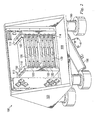
- FIGURE 2 is an illustration of selected portions of test configuration apparatus 100.
- the frame of the configuration apparatus 100 includes structural support 183 and the base plate 180.
- the test subject 120 includes a plurality of circuit cards.
- the circuit cards are held in place by card guides 122, which can be seen more clearly in FIGURE 3A.
- the card guides 122 are also the location where the rails 110 abut the test subject 120 and thus are the location where conduction heating and/or conduction cooling of the test subject 120 takes place.
- the LN 2 is piped into the rails 110 through openings on the bottom of the rails 110. This will be illustrated more clearly in FIGURE 3D.
- the LN 2 Once the LN 2 enters the rails 110, it flows through various circular channels emptying into central channels, which extend the entire height of the rails 110, in this embodiment. This will be illustrated more clearly in FIGURE 3C. Openings 102 of the central channels are illustrated in FIGURE 2 as the center openings in the top surface of the rails 110, which openings 102 are flanked on two sides by three openings 112 for receiving the heated rods. From the central channels, the LN 2 flows into the cooling tubes, the openings 114 of which can be seen in FIGURE 2.
- the cooling tubes extend the full length of the rails 110 and will be illustrated more clearly in FIGURE 3A.
- the cooling tubes are the location where the LN 2 evaporates, thus conduction cooling the rails 110 and the card guides 122 which conduction cool the test subject 120.
- Variable-sized plugs can be inserted into the openings 114 of the cooling tubes, providing a means for adjusting the amount of cooling of the test subject 120.
- the temperature of each circuit card can be controlled independently from the others.
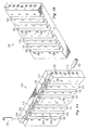
- FIGURE 3A is an illustration of the inner face of the rail 110 of the test configuration apparatus.
- the rail 110 consists of the card guides 122 into which the test subject is inserted.
- the card guides 122 are conduction cooled by evaporation of the LN 2 in the cooling tubes 113 within columns 115.
- Variable-sized plugs can be inserted into the openings 114 of the cooling tubes 113 in order to control the amount of cooling of the test subject.
- Notches 124 in the rail 110 are openings from which the nitrogen gas vents after cooling the rail 110 and the card guides 122. With respect to conduction heating, the heated rods mentioned in connection with FIGURE 1 can be inserted into the openings 112 to the heating tubes in the rail 110.
- FIGURE 3B is an illustration of an alternate view of the inner face of the rail 110 of the test configuration apparatus.
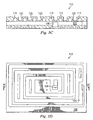
- FIGURE 3C is a schematic diagram of a vertical cross-section of the short side of the rail 110.
- FIGURE 3D is a schematic diagram of a vertical cross-section of the long side of the rail 110.
- LN 2 enters the rail 110 through slot 108.
- the LN 2 is then circulated through the rail 110 via the circular channels 104 until it reaches the opening 106 to the central channel 103.
- the LN 2 flows into the central channel 103, which then distributes the LN 2 to each of the vertical cooling tubes 113.
- the LN 2 flows through the various channels, it evaporates, conduction cooling the rail 110 and card guides 122, which conduction cools the test subject.
- HALT Highly Accelerated Stress Screening
Landscapes
- Engineering & Computer Science (AREA)
- Computer Hardware Design (AREA)
- Microelectronics & Electronic Packaging (AREA)
- General Engineering & Computer Science (AREA)
- Physics & Mathematics (AREA)
- General Physics & Mathematics (AREA)
- Investigating Strength Of Materials By Application Of Mechanical Stress (AREA)
Abstract
Description
- This invention relates generally to the field of highly-accelerated life testing (HALT) fixtures and, more particularly, to a conduction-cooled accelerated test fixture.
- It is important for a manufacturer to test its products before releasing them to the public to ensure that the products function reliably when released. Faulty or dysfunctional products can often cause consumer confidence in the manufacturer to decrease, and in addition, can have costly repercussions for the manufacturer consisting of, among other things, product recalls, product liability suits, and the like. However, thorough testing of consumer products can be realized through the use of HALT fixtures.
- HALT fixtures are designed to test products to uncover design defects and weaknesses in electronic and electro-mechanical assemblies by applying extreme vibrational and thermal stresses to the product. The thermal stresses can consist of rapid and extreme temperature changes. Through the application of such stresses to a product during HALT testing, the HALT fixture can emulate in a brief time frame (i.e., a few days or hours) the entire lifetime of stresses that a product will typically undergo during conventional use.
- According to one embodiment of the invention, a testing apparatus for executing highly accelerated life testing on at least one test subject includes at least one structure operable to thermally stress the test subject via conduction and at least one pneumatic hammer operable to input imparting vibrations to the test subject. According to another embodiment of the invention, a method for executing highly accelerated life testing of at least one test subject includes applying a thermal stress to the test subject via conduction at a rate of change of at least 8ºC per minute and imparting vibrations to the test subject at a rate of at least 3Gs rms.
- Certain embodiments of the invention may provide numerous technical advantages. For example, a technical advantage of one embodiment may include the reduction of overlooked design flaws or weaknesses, which reduction results from more accurate emulation of the test subject's thermal environment during HALT testing. An additional technical advantage of this embodiment and/or of an alternate embodiment may include chamber-free HALT testing.
- Although specific advantages have been enumerated above, various embodiments may include all, some, or none of the enumerated advantages. Additionally, other technical advantages may become readily apparent to one of ordinary skill in the art after review of the following figures and description.
- For a more complete understanding of example embodiments of the present invention and its advantages, reference is now made to the following description, taken in conjunction with the accompanying drawings, in which:
- FIGURE 1 is a schematic diagram of an example embodiment of a testing apparatus housed inside of a chamber;
- FIGURE 2 is an illustration of the testing apparatus of FIGURE 1;
- FIGURE 3A is an illustration of the inner face of a rail of the testing apparatus of FIGURE 1;
- FIGURE 3B is an illustration of an alternate view of the inner face of the rail of FIGURE 3A;
- FIGURE 3C is a schematic diagram of a vertical cross-section of the short side of the rail of FIGURE 3A; and
- FIGURE 3D is a schematic diagram of a vertical cross-section of the long side of the rail of FIGURE 3A.
- It should be understood at the outset that although example embodiments of the present invention are illustrated below, the present invention may be implemented using any number of techniques, whether currently known or in existence. The present invention should in no way be limited to the example embodiments, drawings, and techniques illustrated below, including the embodiments and implementation illustrated and described herein. Additionally, the drawings are not necessarily drawn to scale.
- FIGURE 1 is a schematic diagram of an example embodiment of a
testing apparatus 100 housed inside of achamber 184. Thetesting apparatus 100 is operable to stress atest subject 120 by applying either or both of a thermal stress and vibrational stress to thetest subject 120. Thetest subject 120 can include one or more electrical circuit cards or other electrical components. In one example implementation, thetest subject 120 is a circuit card that contains a protective cover; however,test configuration apparatus 100 may be used with a variety of types of test subjects. - The
testing apparatus 100 includes, in this embodiment, a pair ofstructures 110 for thermally stressing thetest subject 120 via conduction heating and/or conduction cooling. In this embodiment,structures 110 are referred to asrails 110 and are illustrated in greater detail in FIGURES 2 through 3D. Conduction heating and/or conduction cooling of thetest subject 120 occurs by first heating and/or cooling therails 110, which then conduction heat and/or conduction cool thetest subject 120. In one embodiment, therails 110 abut the edges oftest subject 120, which allows the heating and/or cooling by conduction to take place. - Conduction cooling may take place, in one embodiment, by first introducing liquid nitrogen (LN2) into a
pipe 130; however, other cooling fluids may be utilized. - Previous HALT systems cooled and/or heated a test subject by convection, blowing cold and/or hot air over the test subject. Convection cooling, however, is not effective when testing a high-powered rail-cooled test subject because convection cooling does not accurately simulate the environment that the test subject is exposed to in the field. In particular, certain temperature gradients that the test subject is exposed to in the field cannot be recreated in a test setting by blowing cold and/or hot air over the test subject. In contrast, thermal stress testing of the test subject by conduction cooling and/or conduction heating more accurately simulates the environment that the test subject is exposed to in the field. Additionally, cooling and/or heating by conduction, as opposed to convection, in one embodiment, maintains a dry nitrogen atmosphere around the test subject, thereby eliminating potential electrical shorts due to moisture condensation.
- Referring back to FIGURE 1, the LN2 flows through the
pipe 130 and enters therails 110 through openings at the bottom of therails 110. After entering therails 110, the LN2 flows throughout channels inside of therails 110, as is illustrated in, and described in greater detail in conjunction with, FIGURES 3C and 3D. As the LN2 flows through the internal channels of therails 110, the LN2 evaporates, thereby causing therails 110 to lose heat. Because the edges oftest subject 120 abut therails 110, the heat loss experienced by thetest subject 120 is transferred to therails 110, thereby conduction cooling thetest subject 120. After the LN2 evaporates, the nitrogen gas exits the rails and vents across thetest subject 120. This process will be further described in connection with FIGURE 3A. It is noted that, in one embodiment, neither the LN2 nor the nitrogen gas comes into contact with the electrical components of the card. Conduction cooling thetest subject 120 provides a benefit of more accurately emulating the thermal environment of thetest subject 120. - Conduction heating of the
test subject 120 can take place by introducing one or moreheated rods 172 intorespective openings 112 in therails 110, as illustrated in FIGURE 2. Therods 172 may include cartridge heaters, or other types of heaters. Referring back to FIGURE 1, power is provided to the heated rods through aline 140. When powered, the heated rods heat by conduction therails 110. Because the edges of thetest subject 120 abut therails 110, heat is transferred to thetest subject 120 through conduction. - Additionally, the
testing apparatus 100 vibrationally stresses thetest subject 120. Vibrational stress is generated, in one embodiment, by one or morepneumatic hammers 150 that are attached at oneend 152 to the bottom of abase plate 180 upon which therails 110 are fitted. The other end of eachpneumatic hammer 150 is left unattached so that it can impart vibrations to thetesting apparatus 100 when air is supplied to thepneumatic hammers 150. The air that drives thepneumatic hammers 150 may be supplied to thetesting apparatus 100 viapipe 170. Thetesting apparatus 100 is fitted withshock mounts 160 between thebase plate 180 and thebase 182 of thetesting apparatus 100 for dampening the vibrations generated by thepneumatic hammers 150, in one embodiment. - In one embodiment of the invention, the
testing apparatus 100 is housed inside of achamber 184.Chamber 184 includeswalls 186 that act as sound proofing, dampening the sound generated by thetesting apparatus 100. Although one embodiment of thetesting apparatus 100 utilizes achamber 184 as a housing, thetesting apparatus 100 can be operated without such achamber 184, as can be seen in FIGURE 2. - A
computer 190 controls the test settings of thetesting apparatus 100.Computer 190 controls the test settings of thetesting apparatus 100 by transmitting signals through aline 191 to anenvironment controller 192.Environment controller 192, in turn, controls the heating, shaking, as well as cooling of thetest subject 120 viacontrol lines Computer 190 may also receive test results from thetesting apparatus 100 while thermal and vibrational stresses are applied to thetest subject 120. Additional details oftest configuration apparatus 100 are described in conjunction with FIGURES 2 through 3D. - FIGURE 2 is an illustration of selected portions of
test configuration apparatus 100. The frame of theconfiguration apparatus 100 includesstructural support 183 and thebase plate 180. In this embodiment, thetest subject 120 includes a plurality of circuit cards. The circuit cards are held in place by card guides 122, which can be seen more clearly in FIGURE 3A. The card guides 122 are also the location where therails 110 abut thetest subject 120 and thus are the location where conduction heating and/or conduction cooling of thetest subject 120 takes place. - With respect to conduction cooling, the LN2 is piped into the
rails 110 through openings on the bottom of therails 110. This will be illustrated more clearly in FIGURE 3D. Once the LN2 enters therails 110, it flows through various circular channels emptying into central channels, which extend the entire height of therails 110, in this embodiment. This will be illustrated more clearly in FIGURE 3C.Openings 102 of the central channels are illustrated in FIGURE 2 as the center openings in the top surface of therails 110, whichopenings 102 are flanked on two sides by threeopenings 112 for receiving the heated rods. From the central channels, the LN2 flows into the cooling tubes, theopenings 114 of which can be seen in FIGURE 2. The cooling tubes extend the full length of therails 110 and will be illustrated more clearly in FIGURE 3A. The cooling tubes are the location where the LN2 evaporates, thus conduction cooling therails 110 and the card guides 122 which conduction cool thetest subject 120. Variable-sized plugs can be inserted into theopenings 114 of the cooling tubes, providing a means for adjusting the amount of cooling of thetest subject 120. In one embodiment, because eachopening 114 is associated with aspecific card guide 122, the temperature of each circuit card can be controlled independently from the others. - FIGURE 3A is an illustration of the inner face of the
rail 110 of the test configuration apparatus. Therail 110 consists of the card guides 122 into which the test subject is inserted. As mentioned in FIGURE 2, the card guides 122 are conduction cooled by evaporation of the LN2 in thecooling tubes 113 withincolumns 115. Variable-sized plugs can be inserted into theopenings 114 of the coolingtubes 113 in order to control the amount of cooling of the test subject.Notches 124 in therail 110 are openings from which the nitrogen gas vents after cooling therail 110 and the card guides 122. With respect to conduction heating, the heated rods mentioned in connection with FIGURE 1 can be inserted into theopenings 112 to the heating tubes in therail 110. - FIGURE 3B is an illustration of an alternate view of the inner face of the
rail 110 of the test configuration apparatus. - The conduction cooling of the rails will be described in more detail in FIGURES 3C and 3D. FIGURE 3C is a schematic diagram of a vertical cross-section of the short side of the
rail 110. - FIGURE 3D is a schematic diagram of a vertical cross-section of the long side of the
rail 110. When thermally stressing the test subject by conduction cooling, LN2 enters therail 110 throughslot 108. The LN2 is then circulated through therail 110 via thecircular channels 104 until it reaches theopening 106 to thecentral channel 103. The LN2 flows into thecentral channel 103, which then distributes the LN2 to each of thevertical cooling tubes 113. As the LN2 flows through the various channels, it evaporates, conduction cooling therail 110 and card guides 122, which conduction cools the test subject. - The teachings of the invention described hereinabove are applicable to testing purposes other than HALT, such as Highly Accelerated Stress Screening (HASS).
- Numerous other changes, substitutions, variations, alterations and modifications may be ascertained by those skilled in the art and it is intended that the present invention encompass all such changes, substitutions, variations, alterations and modifications as falling within the spirit and scope of the appended claims.
Claims (20)
- A testing apparatus for executing testing on at least one test subject, comprising:a first set of channels for cooling the at least one test subject by conduction, comprising:at least one first cooling channel operable to receive a supply of liquid nitrogen and further operable to distribute the supply of liquid nitrogen to at least one second cooling channel;the at least one second cooling channel, connected to the at least one first cooling channel, operable to receive the supply of liquid nitrogen from the at least one first cooling channel and further operable to distribute the supply of liquid nitrogen to at least one third cooling channel; andthe at least one third cooling channel, connected to the at least one second cooling channel, operable to receive the supply of liquid nitrogen from the at least one second cooling channel and further operable to cool by conduction a structure that is operable to cool by conduction the test subject; anda second set of channels for heating the at least one test subject by conduction, comprising:at least one first heating channel operable to receive at least one heating rod and further operable to heat by conduction a structure that is operable to heat by conduction the at least one test subject.
- The testing apparatus of claim 1, wherein the at least one third cooling channel is at least substantially perpendicular to the at least one first heating channel.
- The testing apparatus of claim 1 or claim 2, wherein the at least one third cooling channel comprises:vents operable to allow nitrogen gas to exit from the at least one third cooling channel; andopenings operable to regulate the cooling of the structure that is operable to cool by conduction the at least one test subject.
- A testing apparatus for executing testing on at least one test subject, comprising:at least one structure operable to thermally stress the test subject via conduction; andat least one pneumatic hammer operable to input imparting vibrations to the test subject.
- The testing apparatus of claim 4, and further comprising at least one shock mount associated with the testing apparatus, the at least one shock mount having vibration dampening capability.
- The testing apparatus of claim 4 or claim 5, wherein the at least one structure is operable to thermally stress the test subject via conduction of heat to the test subject.
- The testing apparatus of any of claims 4 to 6, wherein the at least one structure is operable to thermally stress the test subject via conduction cooling.
- The testing apparatus of any of claims 4 to 7, and further comprising the test subject, wherein the test subject is a circuit card.
- The testing apparatus of any of claims 4 to 8, wherein the at least one structure abuts the edges of the test subject.
- The testing apparatus of any of claims 4 to 9, and further comprising a liquid nitrogen supply associated with the at least one structure; and
a plurality of chambers formed in the at least one structure and containing liquid nitrogen from the supply for cooling the test subject. - The testing apparatus of any of claims 4 to 10, and further comprising heated rods disposed within the at least one structure for thermally stressing the test subject via conduction.
- A method for executing testing of at least one test subject comprising:applying a thermal stress to the test subject via conduction at a rate of change of at least 8ºC per minute; andimparting vibrations to the test subject at a rate of at least 3Gs rms.
- The method of claim 12, wherein applying a thermal stress comprises cooling the test subject by conduction.
- The method of claim 12 or claim 13, wherein applying a thermal stress comprises heating the test subject by conduction.
- The method of any of claims 12 to 14, wherein the vibrations are imparted to the test subject by at least one pneumatic hammer.
- The method of any of claims 12 to 15, wherein the vibrations are dampened by at least one shock mount.
- The method of any of claims 12 to 16, wherein the test subject is a circuit card.
- The method of any of claims 12 to 17, wherein at least one structure for applying a thermal stress to the test subject via conduction abuts the edges of the test subject.
- The method of any of claims 13 to 18, wherein liquid nitrogen is used for cooling the test subject by conduction.
- The method of any of claims 14 to 19, wherein heated rods are used for heating the test subject by conduction.
Applications Claiming Priority (1)
| Application Number | Priority Date | Filing Date | Title |
|---|---|---|---|
| US11/278,765 US7498831B2 (en) | 2006-04-05 | 2006-04-05 | Conduction-cooled accelerated test fixture |
Publications (1)
| Publication Number | Publication Date |
|---|---|
| EP1843163A1 true EP1843163A1 (en) | 2007-10-10 |
Family
ID=38278937
Family Applications (1)
| Application Number | Title | Priority Date | Filing Date |
|---|---|---|---|
| EP07250936A Withdrawn EP1843163A1 (en) | 2006-04-05 | 2007-03-06 | Conduction-cooled accelerated test fixture |
Country Status (2)
| Country | Link |
|---|---|
| US (2) | US7498831B2 (en) |
| EP (1) | EP1843163A1 (en) |
Cited By (4)
| Publication number | Priority date | Publication date | Assignee | Title |
|---|---|---|---|---|
| CN103616328A (en) * | 2013-11-05 | 2014-03-05 | 西安交通大学 | High acceleration stress screening apparatus used for testing coating life |
| CN103852677A (en) * | 2012-12-04 | 2014-06-11 | 天津市电力公司 | Method for quickly diagnosing and positioning poor contact faults in electronic product |
| CN107632216A (en) * | 2017-08-31 | 2018-01-26 | 阜阳市风雅颂生产力促进中心有限责任公司 | New forms of energy fill electric pile's aging testing device |
| CN110907725A (en) * | 2019-11-20 | 2020-03-24 | 北京航空航天大学 | Electronic product accelerated life test method based on fault behaviors |
Families Citing this family (1)
| Publication number | Priority date | Publication date | Assignee | Title |
|---|---|---|---|---|
| US8186875B2 (en) * | 2008-09-14 | 2012-05-29 | Nuovo Pignone S.P.A. | Method for determining reheat cracking susceptibility |
Citations (7)
| Publication number | Priority date | Publication date | Assignee | Title |
|---|---|---|---|---|
| US5077523A (en) * | 1989-11-03 | 1991-12-31 | John H. Blanz Company, Inc. | Cryogenic probe station having movable chuck accomodating variable thickness probe cards |
| US5166607A (en) * | 1991-05-31 | 1992-11-24 | Vlsi Technology, Inc. | Method and apparatus to heat the surface of a semiconductor die in a device during burn-in while withdrawing heat from device leads |
| EP0611968A1 (en) * | 1993-02-10 | 1994-08-24 | Siemens Schweiz AG | Apparatus for testing modules |
| US5744975A (en) * | 1996-06-06 | 1998-04-28 | International Business Machines Corporation | Enhanced defect elimination process for electronic assemblies via application of sequentially combined multiple stress processes |
| DE19747399A1 (en) * | 1997-10-27 | 1999-05-06 | Siemens Ag | Plug-in errors detection method e.g. for component-equipped circuit boards |
| US20040178808A1 (en) * | 2003-03-13 | 2004-09-16 | Intel Corporation | Thermal stratification test apparatus and method providing cyclical and steady-state stratified environments |
| US7015712B1 (en) * | 2005-04-18 | 2006-03-21 | Hong-Sun Liu | Production line environmental stress screening system |
Family Cites Families (5)
| Publication number | Priority date | Publication date | Assignee | Title |
|---|---|---|---|---|
| US5600257A (en) * | 1995-08-09 | 1997-02-04 | International Business Machines Corporation | Semiconductor wafer test and burn-in |
| US6054869A (en) * | 1998-03-19 | 2000-04-25 | H+W Test Products, Inc. | Bi-level test fixture for testing printed circuit boards |
| US6668570B2 (en) * | 2001-05-31 | 2003-12-30 | Kryotech, Inc. | Apparatus and method for controlling the temperature of an electronic device under test |
| US6771086B2 (en) * | 2002-02-19 | 2004-08-03 | Lucas/Signatone Corporation | Semiconductor wafer electrical testing with a mobile chiller plate for rapid and precise test temperature control |
| KR100542126B1 (en) * | 2003-04-29 | 2006-01-11 | 미래산업 주식회사 | Semiconductor Device Test Handler |
-
2006
- 2006-04-05 US US11/278,765 patent/US7498831B2/en not_active Expired - Fee Related
-
2007
- 2007-03-06 EP EP07250936A patent/EP1843163A1/en not_active Withdrawn
-
2009
- 2009-01-29 US US12/361,886 patent/US7982476B2/en not_active Expired - Fee Related
Patent Citations (7)
| Publication number | Priority date | Publication date | Assignee | Title |
|---|---|---|---|---|
| US5077523A (en) * | 1989-11-03 | 1991-12-31 | John H. Blanz Company, Inc. | Cryogenic probe station having movable chuck accomodating variable thickness probe cards |
| US5166607A (en) * | 1991-05-31 | 1992-11-24 | Vlsi Technology, Inc. | Method and apparatus to heat the surface of a semiconductor die in a device during burn-in while withdrawing heat from device leads |
| EP0611968A1 (en) * | 1993-02-10 | 1994-08-24 | Siemens Schweiz AG | Apparatus for testing modules |
| US5744975A (en) * | 1996-06-06 | 1998-04-28 | International Business Machines Corporation | Enhanced defect elimination process for electronic assemblies via application of sequentially combined multiple stress processes |
| DE19747399A1 (en) * | 1997-10-27 | 1999-05-06 | Siemens Ag | Plug-in errors detection method e.g. for component-equipped circuit boards |
| US20040178808A1 (en) * | 2003-03-13 | 2004-09-16 | Intel Corporation | Thermal stratification test apparatus and method providing cyclical and steady-state stratified environments |
| US7015712B1 (en) * | 2005-04-18 | 2006-03-21 | Hong-Sun Liu | Production line environmental stress screening system |
Cited By (5)
| Publication number | Priority date | Publication date | Assignee | Title |
|---|---|---|---|---|
| CN103852677A (en) * | 2012-12-04 | 2014-06-11 | 天津市电力公司 | Method for quickly diagnosing and positioning poor contact faults in electronic product |
| CN103616328A (en) * | 2013-11-05 | 2014-03-05 | 西安交通大学 | High acceleration stress screening apparatus used for testing coating life |
| CN107632216A (en) * | 2017-08-31 | 2018-01-26 | 阜阳市风雅颂生产力促进中心有限责任公司 | New forms of energy fill electric pile's aging testing device |
| CN107632216B (en) * | 2017-08-31 | 2019-08-27 | 阜阳市风雅颂生产力促进中心有限责任公司 | New forms of energy fill electric pile's aging testing device |
| CN110907725A (en) * | 2019-11-20 | 2020-03-24 | 北京航空航天大学 | Electronic product accelerated life test method based on fault behaviors |
Also Published As
| Publication number | Publication date |
|---|---|
| US7498831B2 (en) | 2009-03-03 |
| US20070255361A1 (en) | 2007-11-01 |
| US20090135879A1 (en) | 2009-05-28 |
| US7982476B2 (en) | 2011-07-19 |
Similar Documents
| Publication | Publication Date | Title |
|---|---|---|
| US7982476B2 (en) | Conduction-cooled accelerated test fixture | |
| US20090082907A1 (en) | Mechanically isolated environmental test chamber | |
| CN109119127B (en) | High-low temperature aging test box for semiconductor memory | |
| CN105416609B (en) | A kind of multi- scenarios method pilot system and test method | |
| US20020154489A1 (en) | Support rack for vibratory testing of printed circuit boards | |
| CN112578149B (en) | Aging equipment for chip reliability test | |
| KR101370462B1 (en) | Test chamber for semiconductor | |
| CA2951378C (en) | Airflow diverter for reduced specimen temperature gradient | |
| CN218330495U (en) | An integral fuel tank vibration test device | |
| CN213091109U (en) | Pencil vibration test device | |
| CN108918147A (en) | It is a kind of bilayer targeting testing device and hot environment test method | |
| KR20170023339A (en) | Apparatus for testing reliability of semiconductor component having vertical loading direction | |
| CN205910141U (en) | A test device for automobile test heat insulating board performance | |
| KR100643837B1 (en) | Smoke supply device for fire tunnel testing equipment of railway tunnel | |
| Smith et al. | The bathtub curve: an alternative explanation | |
| CN110989727A (en) | Accelerometer test temperature control device | |
| US7882891B2 (en) | Precision surface plate | |
| JP7577590B2 (en) | Simple fire resistance test method and column-shaped specimen holder | |
| CN205079920U (en) | High temperature vibration testing appearance | |
| CN111722972A (en) | Memory high-low temperature testing device and testing method thereof | |
| CN223846944U (en) | A sensor-controlled temperature and humidity chamber | |
| CN221612755U (en) | High temperature resistance testing arrangement of sealant | |
| JP4729025B2 (en) | Insulated lens set | |
| CN224122598U (en) | Thermal barrier coating thermal vibration simulation test device | |
| CN222421373U (en) | Thermal insulation panel |
Legal Events
| Date | Code | Title | Description |
|---|---|---|---|
| PUAI | Public reference made under article 153(3) epc to a published international application that has entered the european phase |
Free format text: ORIGINAL CODE: 0009012 |
|
| AK | Designated contracting states |
Kind code of ref document: A1 Designated state(s): AT BE BG CH CY CZ DE DK EE ES FI FR GB GR HU IE IS IT LI LT LU LV MC MT NL PL PT RO SE SI SK TR |
|
| AX | Request for extension of the european patent |
Extension state: AL BA HR MK YU |
|
| 17P | Request for examination filed |
Effective date: 20080318 |
|
| 17Q | First examination report despatched |
Effective date: 20080415 |
|
| AKX | Designation fees paid |
Designated state(s): AT BE BG CH CY CZ DE DK EE ES FI FR GB GR HU IE IS IT LI LT LU LV MC MT NL PL PT RO SE SI SK TR |
|
| STAA | Information on the status of an ep patent application or granted ep patent |
Free format text: STATUS: THE APPLICATION IS DEEMED TO BE WITHDRAWN |
|
| 18D | Application deemed to be withdrawn |
Effective date: 20081028 |