EP1843112A2 - Arrangement to quickly remove the frost from the lower temperature wall of a 0 °C cavity of a refrigerator - Google Patents
Arrangement to quickly remove the frost from the lower temperature wall of a 0 °C cavity of a refrigerator Download PDFInfo
- Publication number
- EP1843112A2 EP1843112A2 EP07104040A EP07104040A EP1843112A2 EP 1843112 A2 EP1843112 A2 EP 1843112A2 EP 07104040 A EP07104040 A EP 07104040A EP 07104040 A EP07104040 A EP 07104040A EP 1843112 A2 EP1843112 A2 EP 1843112A2
- Authority
- EP
- European Patent Office
- Prior art keywords
- wall
- compartment
- arrangement
- resistance element
- rear wall
- Prior art date
- Legal status (The legal status is an assumption and is not a legal conclusion. Google has not performed a legal analysis and makes no representation as to the accuracy of the status listed.)
- Granted
Links
Images

Classifications
-
- F—MECHANICAL ENGINEERING; LIGHTING; HEATING; WEAPONS; BLASTING
- F25—REFRIGERATION OR COOLING; COMBINED HEATING AND REFRIGERATION SYSTEMS; HEAT PUMP SYSTEMS; MANUFACTURE OR STORAGE OF ICE; LIQUEFACTION SOLIDIFICATION OF GASES
- F25D—REFRIGERATORS; COLD ROOMS; ICE-BOXES; COOLING OR FREEZING APPARATUS NOT OTHERWISE PROVIDED FOR
- F25D21/00—Defrosting; Preventing frosting; Removing condensed or defrost water
- F25D21/06—Removing frost
- F25D21/08—Removing frost by electric heating
-
- F—MECHANICAL ENGINEERING; LIGHTING; HEATING; WEAPONS; BLASTING
- F25—REFRIGERATION OR COOLING; COMBINED HEATING AND REFRIGERATION SYSTEMS; HEAT PUMP SYSTEMS; MANUFACTURE OR STORAGE OF ICE; LIQUEFACTION SOLIDIFICATION OF GASES
- F25D—REFRIGERATORS; COLD ROOMS; ICE-BOXES; COOLING OR FREEZING APPARATUS NOT OTHERWISE PROVIDED FOR
- F25D21/00—Defrosting; Preventing frosting; Removing condensed or defrost water
- F25D21/14—Collecting or removing condensed and defrost water; Drip trays
-
- F—MECHANICAL ENGINEERING; LIGHTING; HEATING; WEAPONS; BLASTING
- F25—REFRIGERATION OR COOLING; COMBINED HEATING AND REFRIGERATION SYSTEMS; HEAT PUMP SYSTEMS; MANUFACTURE OR STORAGE OF ICE; LIQUEFACTION SOLIDIFICATION OF GASES
- F25D—REFRIGERATORS; COLD ROOMS; ICE-BOXES; COOLING OR FREEZING APPARATUS NOT OTHERWISE PROVIDED FOR
- F25D23/00—General constructional features
- F25D23/06—Walls
- F25D23/065—Details
-
- F—MECHANICAL ENGINEERING; LIGHTING; HEATING; WEAPONS; BLASTING
- F25—REFRIGERATION OR COOLING; COMBINED HEATING AND REFRIGERATION SYSTEMS; HEAT PUMP SYSTEMS; MANUFACTURE OR STORAGE OF ICE; LIQUEFACTION SOLIDIFICATION OF GASES
- F25D—REFRIGERATORS; COLD ROOMS; ICE-BOXES; COOLING OR FREEZING APPARATUS NOT OTHERWISE PROVIDED FOR
- F25D2321/00—Details or arrangements for defrosting; Preventing frosting; Removing condensed or defrost water, not provided for in other groups of this subclass
- F25D2321/14—Collecting condense or defrost water; Removing condense or defrost water
- F25D2321/142—Collecting condense or defrost water; Removing condense or defrost water characterised by droplet guides
-
- F—MECHANICAL ENGINEERING; LIGHTING; HEATING; WEAPONS; BLASTING
- F25—REFRIGERATION OR COOLING; COMBINED HEATING AND REFRIGERATION SYSTEMS; HEAT PUMP SYSTEMS; MANUFACTURE OR STORAGE OF ICE; LIQUEFACTION SOLIDIFICATION OF GASES
- F25D—REFRIGERATORS; COLD ROOMS; ICE-BOXES; COOLING OR FREEZING APPARATUS NOT OTHERWISE PROVIDED FOR
- F25D2500/00—Problems to be solved
- F25D2500/02—Geometry problems
Definitions
- the present invention relates to an arrangement for rapidly removing the condensate which forms on a lower temperature wall of a 0°C compartment in a refrigerator, in accordance with the introduction to the main claim.
- a 0°C compartment or drawer also known as a crisp drawer, is a cavity present in an upright refrigerator usually between an underlying freezer compartment and an overlying cooling compartment.
- This 0°C compartment can be simply closed by its own door, and may also contain a movable drawer to contain for example vegetables or similar products.
- This compartment is usually refrigerated by the movement (generally forced) of cold air which grazes a compartment rear wall having a first face facing the compartment and a second face, opposite the first, grazed by this flow of cold air. This latter originates from the freezer compartment and grazes said wall, possibly being deviated onto it by a conduit which transfers this air from the freezer compartment to the preservation compartment.
- the 0°C compartment is hence cooled by convection or by conduction/convection to enable temperatures between -2°C and +3°C to be obtained in the compartment, with an average of around 0°C to enable proper preservation of elements such as meat, fish and vegetables.
- a heating element in the form of an electrical resistance element is preferably and advantageously present at the second face of said rear wall to enable automatic defrosting of the 0°C compartment and removal from the first face of said rear wall of any ice which may form on it.
- the water generated by the ice thawing descends along the wall and is collected in a tray positioned below it, from which the water passes into a drainage hole provided in a lower part of this wall close to the bottom wall of the 0°C compartment or directly in this latter. From there the water is removed in known manner from said compartment and subsequently evaporated.
- An object of the present invention is to provide an arrangement enabling rapid and fast drainage of the defrost water and/or of the condensate which forms on the lower temperature wall, i.e. on the rear wall of a 0°C compartment of a refrigerator.
- Another object is to provide an arrangement of the stated type which is of simple construction and application even in currently produced refrigerators.
- FIGS. 1 and 3A show a refrigerator 1 having a freezer compartment 2 and a preservation compartment 3 closed by corresponding doors 2A and 3A.
- a known compartment 4 temperature controlled substantially at zero degrees, is present between the compartments 2 and 3; the compartment 4 is provided with its own door 4A.
- Said compartment 4 is bounded by side walls 6 and 7, a lower wall 8, an upper wall 9 and a rear wall 10.
- This latter presents a first face 11 facing the interior of the compartment 4 and a second face 12 facing a usual conduit 13 for circulating forced air originating in known manner from the compartment 2 and directed towards the compartment 3.
- the wall 10 is cooled by the air passing through the conduit 13, this air also cooling the interior of the compartment 4 by convection or by conduction/convection.
- Ribs 15 are present on the first face 11 of the rear wall 10 and comprise at least two consecutive portions 15A and 15B of different inclinations to the plane of the face 11 of the wall 10, or rather to an axis K lying in that plane and perpendicular to the wall 8 of the compartment (see Figure 3).
- the ribs 15 also enable condensate water formed on the wall 10 to flow towards a lower part 10K of this wall close to the lower wall 8 of the compartment 4, towards a drainage hole 20 provided in this latter at the lower part 10K of said wall 10.
- the different inclination of the consecutive portions 15A, 15B of the ribs 15 enables the water droplets to move rapidly along them, these droplets accelerating along those portions 15B more distant from the drainage hole 20 (and of greater inclination) and slowing down when they reach the portion 15A closer to said hole (of lesser inclination). This enables more rapid defrosting of the of the wall 10 to be achieved.
- each rib 15 can be formed as a broken line and be defined by rectilinear portions or comprise a rectilinear portion (such as the portion 15B in Figures 2 and 3) and a curved portion (such as the portion 15A in Figures 2 and 3), the inclination of this latter being defined by the tangents at its external points, these tangents varying their inclination to the vertical axis K lying on the wall 10 and perpendicular to the lower wall.
- inclination means the angle formed by the rib portion to the vertical axis K lying in the plane of the wall: in this case the more the angle approaches zero degrees, the greater the inclination of that rib portion, this inclination reaching its maximum (angle of 0 degrees) if the rib portion were perfectly parallel to or coinciding with said vertical axis.
- the defrosting is achieved, as stated, by the heating element or resistance element 18 present on the second face 11 of the wall 10.
- this resistance element 18 is arranged to generate greater heat in proximity to the lower part 10K of the wall 10.
- the resistance element 18 is of serpentine shape and comprises a part 18A presenting a series of close-together portions which give this part a greater "resistive density" such that when traversed by current, this part 18A heats up more than the remaining part of the resistance element 18 disposed above the part 18A on the second face 12 of the wall 10.
- the part 18A is disposed on the second face 12 of the rear wall 10 at the lower part 10K of the first face 11.
- the resistivity of the resistance element is constant.
- the resistance element 18 has a variable power density, with a greater power density at the lower part 10K of the wall 10. In this case, the resistance element 18 is present on the face 11 of the wall 10 at a uniform pitch.
- the resistance element 18 having a variable power density which is greater in a portion positioned at the lower part 10K of the wall 10, the greater density part being shaped as the aforesaid part 18A shown in Figure 4.
Landscapes
- Engineering & Computer Science (AREA)
- Chemical & Material Sciences (AREA)
- Combustion & Propulsion (AREA)
- Physics & Mathematics (AREA)
- Mechanical Engineering (AREA)
- Thermal Sciences (AREA)
- General Engineering & Computer Science (AREA)
- Removal Of Water From Condensation And Defrosting (AREA)
- Devices That Are Associated With Refrigeration Equipment (AREA)
- Defrosting Systems (AREA)
- Freezers Or Refrigerated Showcases (AREA)
- Processing Of Solid Wastes (AREA)
Abstract
Description
- The present invention relates to an arrangement for rapidly removing the condensate which forms on a lower temperature wall of a 0°C compartment in a refrigerator, in accordance with the introduction to the main claim.
- A 0°C compartment or drawer, also known as a crisp drawer, is a cavity present in an upright refrigerator usually between an underlying freezer compartment and an overlying cooling compartment. This 0°C compartment can be simply closed by its own door, and may also contain a movable drawer to contain for example vegetables or similar products. This compartment is usually refrigerated by the movement (generally forced) of cold air which grazes a compartment rear wall having a first face facing the compartment and a second face, opposite the first, grazed by this flow of cold air. This latter originates from the freezer compartment and grazes said wall, possibly being deviated onto it by a conduit which transfers this air from the freezer compartment to the preservation compartment. The 0°C compartment is hence cooled by convection or by conduction/convection to enable temperatures between -2°C and +3°C to be obtained in the compartment, with an average of around 0°C to enable proper preservation of elements such as meat, fish and vegetables.
- A heating element in the form of an electrical resistance element is preferably and advantageously present at the second face of said rear wall to enable automatic defrosting of the 0°C compartment and removal from the first face of said rear wall of any ice which may form on it. The water generated by the ice thawing descends along the wall and is collected in a tray positioned below it, from which the water passes into a drainage hole provided in a lower part of this wall close to the bottom wall of the 0°C compartment or directly in this latter. From there the water is removed in known manner from said compartment and subsequently evaporated.
- An object of the present invention is to provide an arrangement enabling rapid and fast drainage of the defrost water and/or of the condensate which forms on the lower temperature wall, i.e. on the rear wall of a 0°C compartment of a refrigerator.
- Another object is to provide an arrangement of the stated type which is of simple construction and application even in currently produced refrigerators.
- These and further objects which will be apparent to the expert of the art are attained by an arrangement in accordance with the accompanying claims.
- The present invention will be more apparent from the accompanying drawings, which are provided by way of non-limiting example and in which:
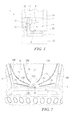
- Figure 1 is a partly sectional side view of a refrigerator provided with the arrangement of the invention;
- Figure 2 is a perspective front view of part of the interior of a 0°C compartment of the refrigerator of Figure 1;
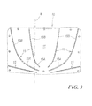
- Figure 3 is a front view of a wall of the compartment of Figure 2; and
- Figure 4 is a rear view of the compartment wall of Figure 3.
- With reference to said figures, these show a refrigerator 1 having a
freezer compartment 2 and apreservation compartment 3 closed by corresponding doors 2A and 3A. In the embodiment shown in the figures, a known compartment 4, temperature controlled substantially at zero degrees, is present between thecompartments - Said compartment 4 is bounded by side walls 6 and 7, a
lower wall 8, an upper wall 9 and arear wall 10. This latter presents afirst face 11 facing the interior of the compartment 4 and asecond face 12 facing ausual conduit 13 for circulating forced air originating in known manner from thecompartment 2 and directed towards thecompartment 3. Thewall 10 is cooled by the air passing through theconduit 13, this air also cooling the interior of the compartment 4 by convection or by conduction/convection.Ribs 15 are present on thefirst face 11 of therear wall 10 and comprise at least two consecutive portions 15A and 15B of different inclinations to the plane of theface 11 of thewall 10, or rather to an axis K lying in that plane and perpendicular to thewall 8 of the compartment (see Figure 3). Water runs along these ribs on thawing of the ice which forms on saidface 11 following activation of a usual heating member or element or defrostingresistance element 18 associated with thesecond face 12 of thewall 10. Theribs 15 also enable condensate water formed on thewall 10 to flow towards a lower part 10K of this wall close to thelower wall 8 of the compartment 4, towards adrainage hole 20 provided in this latter at the lower part 10K ofsaid wall 10. - The different inclination of the consecutive portions 15A, 15B of the
ribs 15 enables the water droplets to move rapidly along them, these droplets accelerating along those portions 15B more distant from the drainage hole 20 (and of greater inclination) and slowing down when they reach the portion 15A closer to said hole (of lesser inclination). This enables more rapid defrosting of the of thewall 10 to be achieved. It should be noted that eachrib 15 can be formed as a broken line and be defined by rectilinear portions or comprise a rectilinear portion (such as the portion 15B in Figures 2 and 3) and a curved portion (such as the portion 15A in Figures 2 and 3), the inclination of this latter being defined by the tangents at its external points, these tangents varying their inclination to the vertical axis K lying on thewall 10 and perpendicular to the lower wall. Finally, it should be noted that the term "inclination"" means the angle formed by the rib portion to the vertical axis K lying in the plane of the wall: in this case the more the angle approaches zero degrees, the greater the inclination of that rib portion, this inclination reaching its maximum (angle of 0 degrees) if the rib portion were perfectly parallel to or coinciding with said vertical axis. - The defrosting is achieved, as stated, by the heating element or
resistance element 18 present on thesecond face 11 of thewall 10. According to a further characteristic of the invention, thisresistance element 18 is arranged to generate greater heat in proximity to the lower part 10K of thewall 10. To achieve this, in one embodiment shown in Figure 4, theresistance element 18 is of serpentine shape and comprises a part 18A presenting a series of close-together portions which give this part a greater "resistive density" such that when traversed by current, this part 18A heats up more than the remaining part of theresistance element 18 disposed above the part 18A on thesecond face 12 of thewall 10. - The part 18A is disposed on the
second face 12 of therear wall 10 at the lower part 10K of thefirst face 11. In this embodiment, the resistivity of the resistance element is constant. - In a variant of the invention, the
resistance element 18 has a variable power density, with a greater power density at the lower part 10K of thewall 10. In this case, theresistance element 18 is present on theface 11 of thewall 10 at a uniform pitch. - In a further variant, a combination of the two aforesaid solutions is provided, in this case the
resistance element 18 having a variable power density which is greater in a portion positioned at the lower part 10K of thewall 10, the greater density part being shaped as the aforesaid part 18A shown in Figure 4. - By virtue of the present invention, a zero degree preservation compartment is obtained which can be rapidly defrosted because of the particular arrangement of the
ribs 15 and theresistance element 18. Other embodiments are possible in the light of the aforegoing description and are therefore to be considered as falling within the scope of the present document.
Claims (7)
- An arrangement for rapidly removing the condensate and/or defrost water from the lower temperature wall (10) of a 0°C compartment or drawer (4) in a refrigerator (1), said compartment (4) being bounded by side walls (6, 7), an upper wall (9), a lower wall (8) and a rear wall (10), the rear wall (10) being refrigerated and presenting on a face (11) facing the interior of the compartment (4) a series of drainage ribs (15) arranged to direct the defrost water and/or condensate towards a drainage hole (20) positioned at the bottom of said wall (10), a defrost resistance element (18) being present on a second face (12) of the rear wall (10) opposite the first (11), characterised in that the ribs (15) present at least two portions (15A, 15B) with different inclinations, the defrost resistance element (18) being arranged to generate greater heat in proximity to a lower portion (10K) of the wall (10) close to the lower wall (8) of the compartment (4).
- An arrangement as claimed in claim 1, characterised in that the rib (15) has at least one rectilinear portion (15B).
- An arrangement as claimed in claim 1, characterised in that the rib (15) has at least one curved portion (15A).
- An arrangement as claimed in claims 2 and 3, characterised in that the rib presents a first curved portion (15A) at least terminating in the lower portion (10K) of the rear wall (10), and a second rectilinear portion (15B) connected to the first and positioned along a wall part distant from said lower part (10K).
- An arrangement as claimed in claim 1, characterised in that the defrost resistance element (18) is of serpentine shape and presents a wall (18A) having a series of close-together portions which confer a high resistive density on said part, said part (18A) corresponding with the lower portion (10K) of the rear wall (10) of the compartment (4).
- An arrangement as claimed in claim 1, characterised in that the defrost resistance element (18) has a variable power density which is greater in a part positioned at the lower portion (10K) of the wall (10) of the compartment (4).
- An arrangement as claimed in claims 5 and 6, characterised in that the greater power density part is the close-together portion part of the resistance element (18A) corresponding in position with the lower portion (10K) of the rear wall (10) of the compartment (4).
Priority Applications (1)
| Application Number | Priority Date | Filing Date | Title |
|---|---|---|---|
| PL07104040T PL1843112T3 (en) | 2006-04-07 | 2007-03-13 | Arrangement to quickly remove the frost from the lower temperature wall of a 0 °C cavity of a refrigerator |
Applications Claiming Priority (1)
| Application Number | Priority Date | Filing Date | Title |
|---|---|---|---|
| IT000132U ITMI20060132U1 (en) | 2006-04-07 | 2006-04-07 | ARRANGEMENT FOR QUICKLY REMOVING THE WALL CONDENSATION AT LESS TEMPERATURE OF A COMPARTMENT AT 0 ° C IN A REFRIGERATOR |
Publications (3)
| Publication Number | Publication Date |
|---|---|
| EP1843112A2 true EP1843112A2 (en) | 2007-10-10 |
| EP1843112A3 EP1843112A3 (en) | 2007-12-19 |
| EP1843112B1 EP1843112B1 (en) | 2009-06-10 |
Family
ID=38229844
Family Applications (1)
| Application Number | Title | Priority Date | Filing Date |
|---|---|---|---|
| EP07104040A Not-in-force EP1843112B1 (en) | 2006-04-07 | 2007-03-13 | Arrangement to quickly remove the frost from the lower temperature wall of a 0 °C cavity of a refrigerator |
Country Status (6)
| Country | Link |
|---|---|
| EP (1) | EP1843112B1 (en) |
| AT (1) | ATE433555T1 (en) |
| DE (1) | DE602007001256D1 (en) |
| ES (1) | ES2328413T3 (en) |
| IT (1) | ITMI20060132U1 (en) |
| PL (1) | PL1843112T3 (en) |
Cited By (2)
| Publication number | Priority date | Publication date | Assignee | Title |
|---|---|---|---|---|
| ITVR20120036A1 (en) * | 2012-03-05 | 2013-09-06 | Vecam Co S P A | CONDENSATE COLLECTION TANK EQUIPPED WITH A HEATING SYSTEM |
| CN105737485A (en) * | 2014-12-10 | 2016-07-06 | 博西华电器(江苏)有限公司 | Refrigerating device with cover plate |
Citations (2)
| Publication number | Priority date | Publication date | Assignee | Title |
|---|---|---|---|---|
| GB2175384A (en) | 1985-05-15 | 1986-11-26 | Hotpoint Ltd | Refrigerators |
| US20020069659A1 (en) | 2000-09-21 | 2002-06-13 | Young-Gil Lee | Kim-chi refrigerator having a heater for a vegetable chamber |
Family Cites Families (5)
| Publication number | Priority date | Publication date | Assignee | Title |
|---|---|---|---|---|
| US1855432A (en) * | 1931-08-03 | 1932-04-26 | Hussman Ligonier Company | Baffle and drip pan for refrigerators |
| BR8102363U (en) * | 2001-09-05 | 2003-07-08 | Multibras Eletrodomesticos Sa | Defrost water directing arrangement in refrigerators |
| DE10259765A1 (en) * | 2002-12-19 | 2004-07-01 | BSH Bosch und Siemens Hausgeräte GmbH | Inner container for a refrigerator |
| DE10360901A1 (en) * | 2003-12-23 | 2005-07-21 | BSH Bosch und Siemens Hausgeräte GmbH | Housing for a refrigeration device |
| DE202004008765U1 (en) * | 2004-06-01 | 2004-09-09 | Berto, Elisabeth | Defrosting system for use on refrigerators has an electrically heated foil coupled to a controller |
-
2006
- 2006-04-07 IT IT000132U patent/ITMI20060132U1/en unknown
-
2007
- 2007-03-13 ES ES07104040T patent/ES2328413T3/en active Active
- 2007-03-13 AT AT07104040T patent/ATE433555T1/en not_active IP Right Cessation
- 2007-03-13 EP EP07104040A patent/EP1843112B1/en not_active Not-in-force
- 2007-03-13 DE DE602007001256T patent/DE602007001256D1/en active Active
- 2007-03-13 PL PL07104040T patent/PL1843112T3/en unknown
Patent Citations (2)
| Publication number | Priority date | Publication date | Assignee | Title |
|---|---|---|---|---|
| GB2175384A (en) | 1985-05-15 | 1986-11-26 | Hotpoint Ltd | Refrigerators |
| US20020069659A1 (en) | 2000-09-21 | 2002-06-13 | Young-Gil Lee | Kim-chi refrigerator having a heater for a vegetable chamber |
Cited By (3)
| Publication number | Priority date | Publication date | Assignee | Title |
|---|---|---|---|---|
| ITVR20120036A1 (en) * | 2012-03-05 | 2013-09-06 | Vecam Co S P A | CONDENSATE COLLECTION TANK EQUIPPED WITH A HEATING SYSTEM |
| EP2636966A1 (en) * | 2012-03-05 | 2013-09-11 | VECAM-CO S.p.A. | Condensate collecting tank with a heating system |
| CN105737485A (en) * | 2014-12-10 | 2016-07-06 | 博西华电器(江苏)有限公司 | Refrigerating device with cover plate |
Also Published As
| Publication number | Publication date |
|---|---|
| ATE433555T1 (en) | 2009-06-15 |
| EP1843112A3 (en) | 2007-12-19 |
| EP1843112B1 (en) | 2009-06-10 |
| DE602007001256D1 (en) | 2009-07-23 |
| ITMI20060132U1 (en) | 2007-10-08 |
| ES2328413T3 (en) | 2009-11-12 |
| PL1843112T3 (en) | 2009-11-30 |
Similar Documents
| Publication | Publication Date | Title |
|---|---|---|
| KR101650303B1 (en) | Ice maker unit and refrigerator having the same | |
| RU2413143C1 (en) | Refrigerator | |
| KR20100033762A (en) | Heat-exchange apparatus of food and refrigerator having the same | |
| KR20160105218A (en) | Refrigerator | |
| CN208688080U (en) | refrigerator | |
| JP2018141625A (en) | refrigerator | |
| CN111609633B (en) | air-cooled refrigerator | |
| EP1843112B1 (en) | Arrangement to quickly remove the frost from the lower temperature wall of a 0 °C cavity of a refrigerator | |
| CN1223819C (en) | Refrigerator having defreezing chamber | |
| WO2013084473A1 (en) | Refrigerator | |
| AU2020346937B2 (en) | Refrigerator | |
| EP2593734B1 (en) | No-frost refrigerator | |
| JP6426350B2 (en) | refrigerator | |
| JP5529218B2 (en) | refrigerator | |
| JP5165522B2 (en) | refrigerator | |
| JP5053238B2 (en) | refrigerator | |
| JP6744731B2 (en) | refrigerator | |
| JP2009092340A (en) | refrigerator | |
| JP3599977B2 (en) | Refrigerator drainage device | |
| CN203478781U (en) | Refrigerator | |
| JP6866995B2 (en) | refrigerator | |
| CN213396082U (en) | Rapid freezing device for boneless chicken feet | |
| US2637180A (en) | Electrical defrosting arrangement for refrigerators | |
| CN112484370A (en) | Refrigerator with a door | |
| EP0272761A2 (en) | Upright freezer with selective frost accumulation |
Legal Events
| Date | Code | Title | Description |
|---|---|---|---|
| PUAI | Public reference made under article 153(3) epc to a published international application that has entered the european phase |
Free format text: ORIGINAL CODE: 0009012 |
|
| AK | Designated contracting states |
Kind code of ref document: A2 Designated state(s): AT BE BG CH CY CZ DE DK EE ES FI FR GB GR HU IE IS IT LI LT LU LV MC MT NL PL PT RO SE SI SK TR |
|
| AX | Request for extension of the european patent |
Extension state: AL BA HR MK YU |
|
| PUAL | Search report despatched |
Free format text: ORIGINAL CODE: 0009013 |
|
| AK | Designated contracting states |
Kind code of ref document: A3 Designated state(s): AT BE BG CH CY CZ DE DK EE ES FI FR GB GR HU IE IS IT LI LT LU LV MC MT NL PL PT RO SE SI SK TR |
|
| AX | Request for extension of the european patent |
Extension state: AL BA HR MK YU |
|
| 17P | Request for examination filed |
Effective date: 20080610 |
|
| 17Q | First examination report despatched |
Effective date: 20080717 |
|
| AKX | Designation fees paid |
Designated state(s): AT BE BG CH CY CZ DE DK EE ES FI FR GB GR HU IE IS IT LI LT LU LV MC MT NL PL PT RO SE SI SK TR |
|
| GRAP | Despatch of communication of intention to grant a patent |
Free format text: ORIGINAL CODE: EPIDOSNIGR1 |
|
| GRAS | Grant fee paid |
Free format text: ORIGINAL CODE: EPIDOSNIGR3 |
|
| GRAA | (expected) grant |
Free format text: ORIGINAL CODE: 0009210 |
|
| AK | Designated contracting states |
Kind code of ref document: B1 Designated state(s): AT BE BG CH CY CZ DE DK EE ES FI FR GB GR HU IE IS IT LI LT LU LV MC MT NL PL PT RO SE SI SK TR |
|
| REG | Reference to a national code |
Ref country code: GB Ref legal event code: FG4D |
|
| REG | Reference to a national code |
Ref country code: CH Ref legal event code: EP |
|
| REG | Reference to a national code |
Ref country code: IE Ref legal event code: FG4D |
|
| REF | Corresponds to: |
Ref document number: 602007001256 Country of ref document: DE Date of ref document: 20090723 Kind code of ref document: P |
|
| PG25 | Lapsed in a contracting state [announced via postgrant information from national office to epo] |
Ref country code: FI Free format text: LAPSE BECAUSE OF FAILURE TO SUBMIT A TRANSLATION OF THE DESCRIPTION OR TO PAY THE FEE WITHIN THE PRESCRIBED TIME-LIMIT Effective date: 20090610 Ref country code: AT Free format text: LAPSE BECAUSE OF FAILURE TO SUBMIT A TRANSLATION OF THE DESCRIPTION OR TO PAY THE FEE WITHIN THE PRESCRIBED TIME-LIMIT Effective date: 20090610 Ref country code: LT Free format text: LAPSE BECAUSE OF FAILURE TO SUBMIT A TRANSLATION OF THE DESCRIPTION OR TO PAY THE FEE WITHIN THE PRESCRIBED TIME-LIMIT Effective date: 20090610 |
|
| NLV1 | Nl: lapsed or annulled due to failure to fulfill the requirements of art. 29p and 29m of the patents act | ||
| REG | Reference to a national code |
Ref country code: ES Ref legal event code: FG2A Ref document number: 2328413 Country of ref document: ES Kind code of ref document: T3 |
|
| PG25 | Lapsed in a contracting state [announced via postgrant information from national office to epo] |
Ref country code: SE Free format text: LAPSE BECAUSE OF FAILURE TO SUBMIT A TRANSLATION OF THE DESCRIPTION OR TO PAY THE FEE WITHIN THE PRESCRIBED TIME-LIMIT Effective date: 20090910 Ref country code: LV Free format text: LAPSE BECAUSE OF FAILURE TO SUBMIT A TRANSLATION OF THE DESCRIPTION OR TO PAY THE FEE WITHIN THE PRESCRIBED TIME-LIMIT Effective date: 20090610 Ref country code: SI Free format text: LAPSE BECAUSE OF FAILURE TO SUBMIT A TRANSLATION OF THE DESCRIPTION OR TO PAY THE FEE WITHIN THE PRESCRIBED TIME-LIMIT Effective date: 20090610 Ref country code: NL Free format text: LAPSE BECAUSE OF FAILURE TO SUBMIT A TRANSLATION OF THE DESCRIPTION OR TO PAY THE FEE WITHIN THE PRESCRIBED TIME-LIMIT Effective date: 20090610 |
|
| REG | Reference to a national code |
Ref country code: PL Ref legal event code: T3 |
|
| PG25 | Lapsed in a contracting state [announced via postgrant information from national office to epo] |
Ref country code: CZ Free format text: LAPSE BECAUSE OF FAILURE TO SUBMIT A TRANSLATION OF THE DESCRIPTION OR TO PAY THE FEE WITHIN THE PRESCRIBED TIME-LIMIT Effective date: 20090610 Ref country code: RO Free format text: LAPSE BECAUSE OF FAILURE TO SUBMIT A TRANSLATION OF THE DESCRIPTION OR TO PAY THE FEE WITHIN THE PRESCRIBED TIME-LIMIT Effective date: 20090610 Ref country code: EE Free format text: LAPSE BECAUSE OF FAILURE TO SUBMIT A TRANSLATION OF THE DESCRIPTION OR TO PAY THE FEE WITHIN THE PRESCRIBED TIME-LIMIT Effective date: 20090610 Ref country code: IS Free format text: LAPSE BECAUSE OF FAILURE TO SUBMIT A TRANSLATION OF THE DESCRIPTION OR TO PAY THE FEE WITHIN THE PRESCRIBED TIME-LIMIT Effective date: 20091010 |
|
| PG25 | Lapsed in a contracting state [announced via postgrant information from national office to epo] |
Ref country code: SK Free format text: LAPSE BECAUSE OF FAILURE TO SUBMIT A TRANSLATION OF THE DESCRIPTION OR TO PAY THE FEE WITHIN THE PRESCRIBED TIME-LIMIT Effective date: 20090610 Ref country code: BE Free format text: LAPSE BECAUSE OF FAILURE TO SUBMIT A TRANSLATION OF THE DESCRIPTION OR TO PAY THE FEE WITHIN THE PRESCRIBED TIME-LIMIT Effective date: 20090610 |
|
| PG25 | Lapsed in a contracting state [announced via postgrant information from national office to epo] |
Ref country code: PT Free format text: LAPSE BECAUSE OF FAILURE TO SUBMIT A TRANSLATION OF THE DESCRIPTION OR TO PAY THE FEE WITHIN THE PRESCRIBED TIME-LIMIT Effective date: 20091010 Ref country code: BG Free format text: LAPSE BECAUSE OF FAILURE TO SUBMIT A TRANSLATION OF THE DESCRIPTION OR TO PAY THE FEE WITHIN THE PRESCRIBED TIME-LIMIT Effective date: 20090910 |
|
| PLBE | No opposition filed within time limit |
Free format text: ORIGINAL CODE: 0009261 |
|
| STAA | Information on the status of an ep patent application or granted ep patent |
Free format text: STATUS: NO OPPOSITION FILED WITHIN TIME LIMIT |
|
| PG25 | Lapsed in a contracting state [announced via postgrant information from national office to epo] |
Ref country code: DK Free format text: LAPSE BECAUSE OF FAILURE TO SUBMIT A TRANSLATION OF THE DESCRIPTION OR TO PAY THE FEE WITHIN THE PRESCRIBED TIME-LIMIT Effective date: 20090610 |
|
| 26N | No opposition filed |
Effective date: 20100311 |
|
| PG25 | Lapsed in a contracting state [announced via postgrant information from national office to epo] |
Ref country code: MC Free format text: LAPSE BECAUSE OF NON-PAYMENT OF DUE FEES Effective date: 20100331 |
|
| PG25 | Lapsed in a contracting state [announced via postgrant information from national office to epo] |
Ref country code: IE Free format text: LAPSE BECAUSE OF NON-PAYMENT OF DUE FEES Effective date: 20100313 |
|
| PG25 | Lapsed in a contracting state [announced via postgrant information from national office to epo] |
Ref country code: MT Free format text: LAPSE BECAUSE OF FAILURE TO SUBMIT A TRANSLATION OF THE DESCRIPTION OR TO PAY THE FEE WITHIN THE PRESCRIBED TIME-LIMIT Effective date: 20090610 |
|
| PGRI | Patent reinstated in contracting state [announced from national office to epo] |
Ref country code: IT Effective date: 20110501 |
|
| REG | Reference to a national code |
Ref country code: CH Ref legal event code: PL |
|
| PG25 | Lapsed in a contracting state [announced via postgrant information from national office to epo] |
Ref country code: CH Free format text: LAPSE BECAUSE OF NON-PAYMENT OF DUE FEES Effective date: 20110331 Ref country code: LI Free format text: LAPSE BECAUSE OF NON-PAYMENT OF DUE FEES Effective date: 20110331 |
|
| PG25 | Lapsed in a contracting state [announced via postgrant information from national office to epo] |
Ref country code: CY Free format text: LAPSE BECAUSE OF FAILURE TO SUBMIT A TRANSLATION OF THE DESCRIPTION OR TO PAY THE FEE WITHIN THE PRESCRIBED TIME-LIMIT Effective date: 20090610 |
|
| PG25 | Lapsed in a contracting state [announced via postgrant information from national office to epo] |
Ref country code: LU Free format text: LAPSE BECAUSE OF NON-PAYMENT OF DUE FEES Effective date: 20100313 Ref country code: HU Free format text: LAPSE BECAUSE OF FAILURE TO SUBMIT A TRANSLATION OF THE DESCRIPTION OR TO PAY THE FEE WITHIN THE PRESCRIBED TIME-LIMIT Effective date: 20091211 |
|
| PG25 | Lapsed in a contracting state [announced via postgrant information from national office to epo] |
Ref country code: TR Free format text: LAPSE BECAUSE OF FAILURE TO SUBMIT A TRANSLATION OF THE DESCRIPTION OR TO PAY THE FEE WITHIN THE PRESCRIBED TIME-LIMIT Effective date: 20090610 |
|
| PG25 | Lapsed in a contracting state [announced via postgrant information from national office to epo] |
Ref country code: GR Free format text: LAPSE BECAUSE OF FAILURE TO SUBMIT A TRANSLATION OF THE DESCRIPTION OR TO PAY THE FEE WITHIN THE PRESCRIBED TIME-LIMIT Effective date: 20090610 |
|
| REG | Reference to a national code |
Ref country code: FR Ref legal event code: PLFP Year of fee payment: 10 |
|
| PGFP | Annual fee paid to national office [announced via postgrant information from national office to epo] |
Ref country code: DE Payment date: 20160308 Year of fee payment: 10 Ref country code: ES Payment date: 20160211 Year of fee payment: 10 |
|
| PGFP | Annual fee paid to national office [announced via postgrant information from national office to epo] |
Ref country code: FR Payment date: 20160208 Year of fee payment: 10 Ref country code: GB Payment date: 20160309 Year of fee payment: 10 |
|
| PGFP | Annual fee paid to national office [announced via postgrant information from national office to epo] |
Ref country code: IT Payment date: 20160324 Year of fee payment: 10 |
|
| PGFP | Annual fee paid to national office [announced via postgrant information from national office to epo] |
Ref country code: PL Payment date: 20170113 Year of fee payment: 11 |
|
| REG | Reference to a national code |
Ref country code: DE Ref legal event code: R119 Ref document number: 602007001256 Country of ref document: DE |
|
| GBPC | Gb: european patent ceased through non-payment of renewal fee |
Effective date: 20170313 |
|
| REG | Reference to a national code |
Ref country code: FR Ref legal event code: ST Effective date: 20171130 |
|
| PG25 | Lapsed in a contracting state [announced via postgrant information from national office to epo] |
Ref country code: DE Free format text: LAPSE BECAUSE OF NON-PAYMENT OF DUE FEES Effective date: 20171003 Ref country code: FR Free format text: LAPSE BECAUSE OF NON-PAYMENT OF DUE FEES Effective date: 20170331 |
|
| PG25 | Lapsed in a contracting state [announced via postgrant information from national office to epo] |
Ref country code: GB Free format text: LAPSE BECAUSE OF NON-PAYMENT OF DUE FEES Effective date: 20170313 Ref country code: IT Free format text: LAPSE BECAUSE OF NON-PAYMENT OF DUE FEES Effective date: 20170313 |
|
| REG | Reference to a national code |
Ref country code: ES Ref legal event code: FD2A Effective date: 20180704 |
|
| PG25 | Lapsed in a contracting state [announced via postgrant information from national office to epo] |
Ref country code: ES Free format text: LAPSE BECAUSE OF NON-PAYMENT OF DUE FEES Effective date: 20170314 |
|
| PG25 | Lapsed in a contracting state [announced via postgrant information from national office to epo] |
Ref country code: PL Free format text: LAPSE BECAUSE OF NON-PAYMENT OF DUE FEES Effective date: 20180313 |