EP1843075A1 - Repair of composite structures - Google Patents
Repair of composite structures Download PDFInfo
- Publication number
- EP1843075A1 EP1843075A1 EP07251452A EP07251452A EP1843075A1 EP 1843075 A1 EP1843075 A1 EP 1843075A1 EP 07251452 A EP07251452 A EP 07251452A EP 07251452 A EP07251452 A EP 07251452A EP 1843075 A1 EP1843075 A1 EP 1843075A1
- Authority
- EP
- European Patent Office
- Prior art keywords
- adhesive
- doubler
- support
- damaged
- composite
- Prior art date
- Legal status (The legal status is an assumption and is not a legal conclusion. Google has not performed a legal analysis and makes no representation as to the accuracy of the status listed.)
- Granted
Links
Images




Classifications
-
- B—PERFORMING OPERATIONS; TRANSPORTING
- B29—WORKING OF PLASTICS; WORKING OF SUBSTANCES IN A PLASTIC STATE IN GENERAL
- B29C—SHAPING OR JOINING OF PLASTICS; SHAPING OF MATERIAL IN A PLASTIC STATE, NOT OTHERWISE PROVIDED FOR; AFTER-TREATMENT OF THE SHAPED PRODUCTS, e.g. REPAIRING
- B29C73/00—Repairing of articles made from plastics or substances in a plastic state, e.g. of articles shaped or produced by using techniques covered by this subclass or subclass B29D
- B29C73/04—Repairing of articles made from plastics or substances in a plastic state, e.g. of articles shaped or produced by using techniques covered by this subclass or subclass B29D using preformed elements
-
- B—PERFORMING OPERATIONS; TRANSPORTING
- B29—WORKING OF PLASTICS; WORKING OF SUBSTANCES IN A PLASTIC STATE IN GENERAL
- B29C—SHAPING OR JOINING OF PLASTICS; SHAPING OF MATERIAL IN A PLASTIC STATE, NOT OTHERWISE PROVIDED FOR; AFTER-TREATMENT OF THE SHAPED PRODUCTS, e.g. REPAIRING
- B29C73/00—Repairing of articles made from plastics or substances in a plastic state, e.g. of articles shaped or produced by using techniques covered by this subclass or subclass B29D
- B29C73/04—Repairing of articles made from plastics or substances in a plastic state, e.g. of articles shaped or produced by using techniques covered by this subclass or subclass B29D using preformed elements
- B29C73/10—Repairing of articles made from plastics or substances in a plastic state, e.g. of articles shaped or produced by using techniques covered by this subclass or subclass B29D using preformed elements using patches sealing on the surface of the article
-
- Y—GENERAL TAGGING OF NEW TECHNOLOGICAL DEVELOPMENTS; GENERAL TAGGING OF CROSS-SECTIONAL TECHNOLOGIES SPANNING OVER SEVERAL SECTIONS OF THE IPC; TECHNICAL SUBJECTS COVERED BY FORMER USPC CROSS-REFERENCE ART COLLECTIONS [XRACs] AND DIGESTS
- Y10—TECHNICAL SUBJECTS COVERED BY FORMER USPC
- Y10T—TECHNICAL SUBJECTS COVERED BY FORMER US CLASSIFICATION
- Y10T428/00—Stock material or miscellaneous articles
- Y10T428/20—Patched hole or depression
Definitions
- the present invention generally relates to the field of repairing composite structures.
- the invention relates to doubler repair assemblies for composite arcuate flanges.
- Composite structures that are formed of a thermoplastic material such as polyamideimide or polyetherimide are resistant to high temperatures and engine fluids. Thus, these composite structures can be exposed to extreme environments, such as hot engine oils in aircraft engines, which typically cause degradation of mechanical properties of most other elastomeric materials.
- the composite structure may be temperature resistant, the composite structure and its parts are subjected to thermal stresses when rigidly attached to metal structures with significantly different coefficients of thermal expansion, causing cracks in the weaker composite structure.
- arcuate flanges formed of composite materials can easily form cracks radiating from apertures in the flanges where the bolts are positioned. If left unattended, the thermal stresses of the environment may cause the crack to continue to extend to the edge of the flange and cause the entire flange to break.
- a doubler assembly repairs at least one damaged aperture of a composite flange.
- the doubler assembly includes an insert, an adhesive, and a support.
- the insert is positioned in the damaged aperture to provide compressive load transfer through the composite flange.
- the adhesive is positioned directly on at least a portion of the composite flange proximate the damaged aperture.
- the support is positioned over the adhesive.
- FIG. 1 shows a perspective view of composite seal 10 with arcuate flange 12.
- Composite seal 10 is formed of a thermoplastic material and is typically exposed to extreme environments such as high-temperature jet engine oils.
- Arcuate flange 12 extends from composite seal 10 and has a plurality of apertures 14 along its perimeter.
- Bushings 16 and bolts 18 are positioned within apertures 14 of arcuate flange 12 and are used to connect composite seal 10 to a structure, such as a gearbox housing. Due to the extreme environment in which composite seal 10 is typically located, thermal stress resulting from coefficient of thermal expansion mismatches is constantly exerted on composite seal 10, and particularly on apertures 14 of arcuate flange 12. Thus, the area proximate apertures 14 can crack, with the crack typically radiating outward on arcuate flange 12 to the perimeter of composite seal 10.
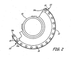
- FIG. 2 shows a top view of arcuate flange 12 having a damaged aperture 14a with crack 15 at wing end 20 and a damaged aperture 14a with crack 15 at non-wing end 22.
- Arcuate flange 12 could be repaired by conventional methods by trimming the cantilevered area, or the area proximate the damaged apertures 14a to remove damaged wing end 20 and damaged non-wing end 22 from arcuate flange 12, leaving only the undamaged apertures 14 on arcuate flange 12.
- the systems and methods of this invention can be used to repair such damage.
- FIG. 3 shows a top view of arcuate flange 12 having doubler 24, and specifically, two different three-hole doublers 24a and 24b.
- Doubler 24 is preferably fabricated having holes 26 with a diameter similar to apertures 14 of arcuate flange 12 to overlap damaged aperture 14a as well as undamaged apertures 14 proximate damaged apertures 14a.
- Doubler 24 is preferably formed of a material that is stronger than the material of composite arcuate flange 12 and that has a coefficient of thermal expansion similar to the coefficient of thermal expansion of the material that arcuate flange 12 is rigidly attached to.
- doubler 24 is designed to act as a repair of an existing part. Cracks 15 radiating from damaged aperture 14a can be bridged using doubler 24, which is operatively connected (i.e. bonded) to arcuate flange 12. While those skilled in the art will understand that doubler 24 can be made of any suitable material, in one embodiment, doubler 24 is made of stainless steel.
- First and second three-hole doublers 24a and 24b as shown in FIG. 3, represent two exemplary uses of three-hole doubler 24.
- only one aperture 14a covered by each three-hole doubler 24a or 24b is damaged, while the remaining two apertures 14 covered by each three-hole doubler 24a or 24b are undamaged.
- damaged aperture 14a is at non-wing end 22 of arcuate flange 12.
- First doubler 24a is thus positioned on arcuate flange 12 such that an end hole 26a of first doubler 24a is positioned over damaged aperture 14a, while the remaining two holes 26b and 26c of three-hole doubler 24a are positioned over undamaged apertures 14.
- Second doubler 24b is positioned on arcuate flange 12 such that center hole 26b of second doubler 24b is positioned over damaged aperture 14a, while the remaining two holes 26a and 26c of three-hole doubler 24b are positioned over undamaged holes 14.
- three-hole doublers 24a and 24b may be most effective if only one of the three apertures that three-hole doublers 24a and 24b cover is damaged, but other embodiments are also possible.
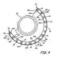
- FIG. 4 Three different exemplary uses of four-hole doublers are shown in FIG. 4.
- Four-hole doublers 24c-24e function in the same manner as three-hole doublers 24a and 24b, except that four-hole doublers 24c-24e are designed with four-holes, rather than just three.
- damaged aperture 14a is on non-wing end 22 of arcuate flange 12.
- Four-hole doubler 24c is thus positioned on arcuate flange 12 such that an end hole 26a of third doubler 24c is positioned over damaged aperture 14a, while the remaining three holes 26b-26d of four-hole doubler 24c may be positioned over undamaged apertures 14.
- the last hole 26d of four-hole doubler 24c will cover an undamaged aperture 14, and at least one of the middle holes 26b and 26c will also cover an undamaged aperture 14.
- Four-hole doubler 24d is shown being used to repair two adjacent damaged apertures 14a.
- four-hole doubler 24d may be positioned on arcuate flange 12 such that center holes 26b and 26c of four-hole doubler 24d are positioned over damaged apertures 14a, while end holes 26a and 26d are positioned over undamaged apertures 14 on either side of damaged apertures 14a.
- Four-hole doubler 24e is shown being used to repair two other adjacent damaged apertures 14a on wing end 20 of arcuate flange 12.
- Four-hole doubler 24e is positioned on arcuate flange 12 such that end hole 26d and center hole 26c of four-hole doubler 24e are positioned over damaged apertures 14a, while end hole 26a and center hole 26b are positioned over undamaged apertures 14.
- four-hole doublers 24c-24e may be most effective if only two of the four apertures that four-hole doublers 24c-24e cover are damaged, but other embodiments are also possible.
- FIGS. 5A and 5B show a partial side view and a partial top view, respectively, of arcuate flange 12 with two undamaged apertures 14 and a damaged aperture 14a.
- a bushing 16 and a bolt 18 are positioned in each aperture 14 of arcuate flange 12.
- Bushing 16 provides a compressive load path for bolt 18 through arcuate flange 12.
- apertures 14 may exhibit damage in the form of cracking. Damaged aperture 14a can be distinguished by crack 15 radiating from damaged aperture 14a to the perimeter of arcuate flange 12.
- doubler 24 shown in FIGS. 6A and 6B
- FIGS. 6A and 6B show a partial side view and a partial top view, respectively, of arcuate flange 12 with doubler 24 installed. Doubler 24 is used to transfer the load across the damaged area of arcuate flange 12 and to provide compressive load distribution at apertures 14.
- a thin sheet, or thick film adhesive 28 may be positioned on top of the surface of arcuate flange 12 to act as an expansion joint between arcuate flange 12 and doubler 24. Before adhesive 28 is positioned on arcuate flange 12, holes 30 may be cut from adhesive 28 to allow inserts 32 to be positioned within apertures 14 and overlap apertures 14.
- Adhesive 28 may comprise any suitable material.
- adhesive 28 may be a fluoroelastomer film that is stable in high temperature environments, for example, DuPont's Viton® fluoroelastomer, available from Eagle Elastomer, Cuyahoga Falls, Ohio.
- fluoroelastomer for adhesive 28 because of its rubbery and ductile properties, which allow for thermal expansion differences when heated to high temperatures.
- fluoroelastomers may be employed for their fluid resistance, which is necessary in extreme environments, such as near hot aircraft engine oil. Doubler 24 may then be positioned over adhesive 28 and thereby become attached to arcuate flange 12, bridging the damaged area of arcuate flange 12.
- FIG. 7 shows an exemplary non-limiting method of installing doubler 24 to an arcuate flange 12 having one or more damaged apertures 14a.
- the surface of arcuate flange 12 may be cleaned and the cracked material may be trimmed away, if desired, as represented by Step 100. Any adhesive in damaged aperture 14a around bushing 16 may also be removed. Additionally, any remaining bushings 16 in apertures 14 on either side of damaged aperture 14a may also be removed.
- repair inserts 32 may then be attached to arcuate flange 12 in any suitable manner, such as by being tack welded to doubler 24 or bonded to arcuate flange 12, as represented by Step 102.
- Inserts 32 may comprise any suitable material, such as for example, a metallic material.
- inserts 32 can be bonded with a high temperature epoxy to damaged apertures 14a, replacing the original bushings 16. Inserts 32 provide a load transfer path through arcuate flange 12 by extending beyond both faces of arcuate flange 12. The rigid bond created by inserts 32 may help restore damaged apertures 14a.
- inserts 32 may be tack welded to metallic doubler 24 for certain locations, such as on wing end 20 or non-wing end 22 where arcuate flange 12 is trimmed away to remove damage, where doubler 24 may be cantilevered over the area that wing end 20 or non-wing end 22 previously occupied to prevent misalignment of arcuate flange 12 during assembly.
- holes 30 may then be cut from adhesive 28 to match up with apertures 14 of arcuate flange 12.
- Doubler 24 is preferably machine-holed with any appropriate number of holes, depending on the needs of the particular arcuate flange 12 (represented by Step 104). After lining up holes 30 in adhesive 28 with inserts 32 positioned in apertures 14 and damaged aperture 14a of arcuate flange 12, adhesive 28 may be applied to the surface of arcuate flange 12, Step 106. Holes 26 of doubler 24 may then be aligned with apertures 14 and 14a and inserts 32, Step 108. In some embodiments, it may be preferable to prevent bonding between inserts 32 and doubler 24. In some embodiments, doubler 24 may be mechanically clamped to arcuate flange 12 while adhesive 28 is curing.
- adhesive 28 When adhesive 28 is initially positioned on arcuate flange 12, adhesive 28 is preferably in a semi-cured state. Adhesive 28 may then be heated to a temperature sufficient to cure adhesive 28 to arcuate flange 12 and doubler 24, as represented by Step 110. Adhesive 28 may also be cured at a sufficient pressure to bring adhesive 28 into contact with both arcuate flange 12 and doubler 24. In some embodiments, adhesive 28 may be heated to a temperature of approximately 320°F to 360°F (160°C to 182°C) for approximately fifteen minutes to thirty minutes under vacuum or at a pressure of approximately 10 pounds per square inch (psi) to 100 psi (69 kPa to 689 kPa).
- psi pounds per square inch
- Doubler 24 may then be allowed to cool to approximately 150°F (65.5°C) before removing the clamp. After doubler 24 has cooled down, adhesive 28 may then be post cured, Step 112. In some embodiments, adhesive 28 may be post cured by being heated to a temperature of approximately 340°F to 360°F (171°C to 182°C) for approximately two to four hours.
- Adhesive is preferably excluded between the contact surfaces of inserts 32 and doubler 24 so that adhesive 28 does not prevent load transfer between doubler 24 and inserts 32.
- the doubler assembly of the present invention can be used to repair damaged apertures of various composite structures, such as those that are exposed to harsh environments.
Landscapes
- Engineering & Computer Science (AREA)
- Mechanical Engineering (AREA)
- Lining Or Joining Of Plastics Or The Like (AREA)
- Laminated Bodies (AREA)
Abstract
Description
- The present invention generally relates to the field of repairing composite structures. In particular, the invention relates to doubler repair assemblies for composite arcuate flanges.
- Composite structures that are formed of a thermoplastic material such as polyamideimide or polyetherimide are resistant to high temperatures and engine fluids. Thus, these composite structures can be exposed to extreme environments, such as hot engine oils in aircraft engines, which typically cause degradation of mechanical properties of most other elastomeric materials. However, while the composite structure may be temperature resistant, the composite structure and its parts are subjected to thermal stresses when rigidly attached to metal structures with significantly different coefficients of thermal expansion, causing cracks in the weaker composite structure. For example, arcuate flanges formed of composite materials can easily form cracks radiating from apertures in the flanges where the bolts are positioned. If left unattended, the thermal stresses of the environment may cause the crack to continue to extend to the edge of the flange and cause the entire flange to break.
- Traditional repair techniques are limited to flange reconstruction techniques using fiberglass/epoxy laminates or either solvent or thermal welded replacement sections. Most of these current repair techniques result in a repair assembly that has inferior mechanical properties when compared to the original structure and also do not account for thermal disparity between parts. One method of repairing the damaged composite structure is to replace the entire structure. However, this can be a costly process, particularly if only a single aperture or only a small percentage of the composite structure is damaged. Another option is to restore only a piece or segment of the flange to a workable condition using a splint or doubler assembly that is applied to the damaged portion of the structure. Additional methods of repairing a damaged composite structure are described in
U.S. Patent No. 5,876,651 andU.S. Patent No. 5,965,240 , issued to Blackburn et al. - According to one aspect of the invention, a doubler assembly repairs at least one damaged aperture of a composite flange. The doubler assembly includes an insert, an adhesive, and a support. The insert is positioned in the damaged aperture to provide compressive load transfer through the composite flange. The adhesive is positioned directly on at least a portion of the composite flange proximate the damaged aperture. The support is positioned over the adhesive.
-
- FIG. 1 is a perspective view of an arcuate flange having apertures.
- FIG. 2 is a top view of the arcuate flange having damaged ends.
- FIG. 3 is a top view of the arcuate flange having a three-hole doubler in two different locations.
- FIG. 4 is a top view of the arcuate flange having a four-hole doubler in three different locations.
- FIG. 5A is a partial side view of a damaged arcuate flange.
- FIG. 5B is a partial top view of the damaged arcuate flange of FIG. 5A.
- FIG. 6A is a partial side view of a repaired arcuate flange having a doubler.
- FIG. 6B is a partial top view of the repaired arcuate flange of FIG. 6A having a doubler assembly.
- FIG. 7 is a block diagram of a method of installing the doubler to the arcuate flange.
- FIG. 1 shows a perspective view of
composite seal 10 witharcuate flange 12.Composite seal 10 is formed of a thermoplastic material and is typically exposed to extreme environments such as high-temperature jet engine oils.Arcuate flange 12 extends fromcomposite seal 10 and has a plurality ofapertures 14 along its perimeter.Bushings 16 and bolts 18 (shown in FIG. 5A) are positioned withinapertures 14 ofarcuate flange 12 and are used to connectcomposite seal 10 to a structure, such as a gearbox housing. Due to the extreme environment in whichcomposite seal 10 is typically located, thermal stress resulting from coefficient of thermal expansion mismatches is constantly exerted oncomposite seal 10, and particularly onapertures 14 ofarcuate flange 12. Thus, the areaproximate apertures 14 can crack, with the crack typically radiating outward onarcuate flange 12 to the perimeter ofcomposite seal 10. - FIG. 2 shows a top view of
arcuate flange 12 having a damagedaperture 14a withcrack 15 atwing end 20 and a damagedaperture 14a withcrack 15 atnon-wing end 22.Arcuate flange 12 could be repaired by conventional methods by trimming the cantilevered area, or the area proximate the damagedapertures 14a to remove damagedwing end 20 and damagednon-wing end 22 fromarcuate flange 12, leaving only theundamaged apertures 14 onarcuate flange 12. Alternatively, the systems and methods of this invention can be used to repair such damage. - FIG. 3 shows a top view of
arcuate flange 12 havingdoubler 24, and specifically, two different three-hole doublers discussion involving doubler 24 refers to all doublers subsequently disclosed.Doubler 24 is preferably fabricated having holes 26 with a diameter similar toapertures 14 ofarcuate flange 12 to overlap damagedaperture 14a as well asundamaged apertures 14 proximate damagedapertures 14a.Doubler 24 is preferably formed of a material that is stronger than the material of compositearcuate flange 12 and that has a coefficient of thermal expansion similar to the coefficient of thermal expansion of the material thatarcuate flange 12 is rigidly attached to. That allows the damaged area ofarcuate flange 12 to be strengthened bydoubler 24, which is designed to act as a repair of an existing part.Cracks 15 radiating from damagedaperture 14a can be bridged usingdoubler 24, which is operatively connected (i.e. bonded) toarcuate flange 12. While those skilled in the art will understand thatdoubler 24 can be made of any suitable material, in one embodiment,doubler 24 is made of stainless steel. - First and second three-
hole doublers hole doubler 24. In these particular embodiments, only oneaperture 14a covered by each three-hole doubler apertures 14 covered by each three-hole doubler first doubler 24a, damagedaperture 14a is atnon-wing end 22 ofarcuate flange 12.First doubler 24a is thus positioned onarcuate flange 12 such that anend hole 26a offirst doubler 24a is positioned over damagedaperture 14a, while the remaining twoholes hole doubler 24a are positioned overundamaged apertures 14. -
Second doubler 24b is positioned onarcuate flange 12 such thatcenter hole 26b ofsecond doubler 24b is positioned over damagedaperture 14a, while the remaining twoholes hole doubler 24b are positioned overundamaged holes 14. In some embodiments, it may be desirable to have no more than six of the fifteenapertures 14 ofarcuate flange 12 covered bydoublers 24, with no more than two damagedapertures 14a having cracks 15 radiating therefrom. As shown in FIG. 3, three-hole doublers hole doublers - Three different exemplary uses of four-hole doublers are shown in FIG. 4. Four-
hole doublers 24c-24e function in the same manner as three-hole doublers hole doublers 24c-24e are designed with four-holes, rather than just three. In four-hole doubler 24c, damagedaperture 14a is onnon-wing end 22 ofarcuate flange 12. Four-hole doubler 24c is thus positioned onarcuate flange 12 such that anend hole 26a ofthird doubler 24c is positioned over damagedaperture 14a, while the remaining threeholes 26b-26d of four-hole doubler 24c may be positioned overundamaged apertures 14. In some embodiments, thelast hole 26d of four-hole doubler 24c will cover anundamaged aperture 14, and at least one of themiddle holes undamaged aperture 14. - Four-
hole doubler 24d is shown being used to repair two adjacentdamaged apertures 14a. To repairarcuate flange 12, four-hole doubler 24d may be positioned onarcuate flange 12 such that center holes 26b and 26c of four-hole doubler 24d are positioned over damagedapertures 14a, whileend holes undamaged apertures 14 on either side of damagedapertures 14a. - Four-
hole doubler 24e is shown being used to repair two other adjacentdamaged apertures 14a onwing end 20 ofarcuate flange 12. Four-hole doubler 24e is positioned onarcuate flange 12 such thatend hole 26d andcenter hole 26c of four-hole doubler 24e are positioned over damagedapertures 14a, whileend hole 26a andcenter hole 26b are positioned overundamaged apertures 14. In some embodiments, it may be desirable to have no more than eight out of fifteenapertures 14 covered bydoublers 24 with no more than four damagedapertures 14a having cracks 15 radiating therefrom. As shown in FIG. 4, four-hole doublers 24c-24e may be most effective if only two of the four apertures that four-hole doublers 24c-24e cover are damaged, but other embodiments are also possible. - FIGS. 5A and 5B show a partial side view and a partial top view, respectively, of
arcuate flange 12 with twoundamaged apertures 14 and a damagedaperture 14a. In operation, abushing 16 and abolt 18 are positioned in eachaperture 14 ofarcuate flange 12.Bushing 16 provides a compressive load path forbolt 18 througharcuate flange 12. When exposed to high thermal stress,apertures 14 may exhibit damage in the form of cracking.Damaged aperture 14a can be distinguished bycrack 15 radiating from damagedaperture 14a to the perimeter ofarcuate flange 12. Whenarcuate flange 12 has a damagedaperture 14a, doubler 24 (shown in FIGS. 6A and 6B) may be used to repairarcuate flange 12. - FIGS. 6A and 6B show a partial side view and a partial top view, respectively, of
arcuate flange 12 withdoubler 24 installed.Doubler 24 is used to transfer the load across the damaged area ofarcuate flange 12 and to provide compressive load distribution atapertures 14. A thin sheet, or thick film adhesive 28 may be positioned on top of the surface ofarcuate flange 12 to act as an expansion joint betweenarcuate flange 12 anddoubler 24. Before adhesive 28 is positioned onarcuate flange 12, holes 30 may be cut from adhesive 28 to allowinserts 32 to be positioned withinapertures 14 and overlapapertures 14.Adhesive 28 may comprise any suitable material. In some embodiments, adhesive 28 may be a fluoroelastomer film that is stable in high temperature environments, for example, DuPont's Viton® fluoroelastomer, available from Eagle Elastomer, Cuyahoga Falls, Ohio. In some embodiments, it may be desirable to use a fluoroelastomer for adhesive 28 because of its rubbery and ductile properties, which allow for thermal expansion differences when heated to high temperatures. Additionally, fluoroelastomers may be employed for their fluid resistance, which is necessary in extreme environments, such as near hot aircraft engine oil.Doubler 24 may then be positioned over adhesive 28 and thereby become attached toarcuate flange 12, bridging the damaged area ofarcuate flange 12. - FIG. 7 shows an exemplary non-limiting method of installing
doubler 24 to anarcuate flange 12 having one or moredamaged apertures 14a. First, the surface ofarcuate flange 12 may be cleaned and the cracked material may be trimmed away, if desired, as represented byStep 100. Any adhesive in damagedaperture 14a aroundbushing 16 may also be removed. Additionally, any remainingbushings 16 inapertures 14 on either side of damagedaperture 14a may also be removed. - In some embodiments, repair inserts 32 may then be attached to
arcuate flange 12 in any suitable manner, such as by being tack welded to doubler 24 or bonded toarcuate flange 12, as represented byStep 102.Inserts 32 may comprise any suitable material, such as for example, a metallic material. In some embodiments, inserts 32 can be bonded with a high temperature epoxy to damagedapertures 14a, replacing theoriginal bushings 16.Inserts 32 provide a load transfer path througharcuate flange 12 by extending beyond both faces ofarcuate flange 12. The rigid bond created byinserts 32 may help restore damagedapertures 14a. In another embodiment, inserts 32 may be tack welded tometallic doubler 24 for certain locations, such as onwing end 20 ornon-wing end 22 wherearcuate flange 12 is trimmed away to remove damage, wheredoubler 24 may be cantilevered over the area thatwing end 20 ornon-wing end 22 previously occupied to prevent misalignment ofarcuate flange 12 during assembly. - In some embodiments, holes 30 may then be cut from adhesive 28 to match up with
apertures 14 ofarcuate flange 12.Doubler 24 is preferably machine-holed with any appropriate number of holes, depending on the needs of the particular arcuate flange 12 (represented by Step 104). After lining upholes 30 in adhesive 28 withinserts 32 positioned inapertures 14 and damagedaperture 14a ofarcuate flange 12, adhesive 28 may be applied to the surface ofarcuate flange 12,Step 106. Holes 26 ofdoubler 24 may then be aligned withapertures Step 108. In some embodiments, it may be preferable to prevent bonding betweeninserts 32 anddoubler 24. In some embodiments,doubler 24 may be mechanically clamped toarcuate flange 12 while adhesive 28 is curing. - When adhesive 28 is initially positioned on
arcuate flange 12, adhesive 28 is preferably in a semi-cured state.Adhesive 28 may then be heated to a temperature sufficient to cure adhesive 28 toarcuate flange 12 anddoubler 24, as represented byStep 110.Adhesive 28 may also be cured at a sufficient pressure to bring adhesive 28 into contact with botharcuate flange 12 anddoubler 24. In some embodiments, adhesive 28 may be heated to a temperature of approximately 320°F to 360°F (160°C to 182°C) for approximately fifteen minutes to thirty minutes under vacuum or at a pressure of approximately 10 pounds per square inch (psi) to 100 psi (69 kPa to 689 kPa).Doubler 24 may then be allowed to cool to approximately 150°F (65.5°C) before removing the clamp. Afterdoubler 24 has cooled down, adhesive 28 may then be post cured,Step 112. In some embodiments, adhesive 28 may be post cured by being heated to a temperature of approximately 340°F to 360°F (171°C to 182°C) for approximately two to four hours. - Any excess adhesive 28 may then be removed from
apertures adhesive 28 around the perimeter ofdoubler 24, as represented byStep 114. Adhesive is preferably excluded between the contact surfaces ofinserts 32 anddoubler 24 so that adhesive 28 does not prevent load transfer betweendoubler 24 and inserts 32. - The doubler assembly of the present invention can be used to repair damaged apertures of various composite structures, such as those that are exposed to harsh environments.
- Although the present invention has been described with reference to preferred embodiments, workers skilled in the art will recognize that changes may be made in form and detail without departing from the scope of the invention. For example, while only three or four aperture doublers were described, the doublers of this invention could have any number of apertures therein.
Claims (25)
- A doubler assembly for repairing at least one damaged aperture (14a) of a composite flange (12), the doubler assembly comprising:an insert (32) positioned in the damaged aperture (14a) capable of providing compressive load transfer through the composite flange (12);an adhesive (28) positioned on at least a portion of the composite flange (12) proximate the damaged aperture (14a); anda support (24) positioned over the adhesive (28).
- The doubler assembly of claim 1, wherein the adhesive (28) is capable of bonding the support (24) to the composite flange (12).
- The doubler assembly of claim 1 or 2, wherein the adhesive (28) is capable of acting as an expansion joint between the composite flange (12) and the support (24).
- The doubler assembly of any preceding claim, wherein the adhesive (28) comprises a fluoroelastomer material.
- The doubler assembly of any preceding claim, wherein the support (24) comprises a metallic material.
- The doubler assembly of any preceding claim, wherein the support (24) comprises at least three apertures therein.
- The doubler assembly of any preceding claim, wherein the support (24) is capable of distributing a load across at least one damaged aperture (14a).
- The doubler assembly of any preceding claim, wherein the insert (32) comprises a metallic material.
- A repair assembly for repairing a damage site of a thermoplastic structure (12) having at least one damaged aperture (14a), the repair assembly comprising:an insert (32) positioned in the damaged aperture (14a) capable of providing compressive load transfer through the thermoplastic structure;an expandable adhesive (28) that is stable in harsh environments and is positioned on the thermoplastic structure; andan overlapping support (24) positioned on the expandable adhesive (28), the overlapping support (24) having a coefficient of thermal expansion greater than a coefficient of thermal expansion of the thermoplastic structure (12).
- The repair assembly of claim 9, wherein the overlapping support (24) is capable of spreading a compressive load across a damage site.
- The repair assembly of claim 10, wherein the damage site is an area proximate the damaged aperture (14a) of the thermoplastic structure (12).
- The repair assembly of claim 9, 10 or 11, wherein the adhesive (28) is a fluoroelastomer.
- The repair assembly of any of claims 9 to 12, wherein the overlapping support (24) is bonded to the thermoplastic structure (12) by the adhesive (28).
- The repair assembly of any of claims 9 to 13, wherein the adhesive (28) is in a semi-cured state prior to bonding.
- The repair assembly of any of claims 9 to 14, wherein the insert (32) comprises a metallic material.
- The repair assembly of any of claims 9 to 15, wherein the overlapping support (24) comprises a metallic material.
- A method of repairing a composite arcuate flange (12) having at least one damaged aperture (14a), the method comprising:positioning an insert (32) within the damaged aperture (14a);attaching the insert (32) to the damaged aperture (14a);applying an adhesive (28) to the composite arcuate flange (12);positioning a support structure (24) on the adhesive (28); andbonding the support structure (24) to the composite arcuate flange (12).
- The method of claim 17, wherein bonding the support structure (24) to the composite arcuate flange (12) comprises curing the adhesive (28) at a temperature of about 320 to 360 degrees Fahrenheit (160°C to 182°C).
- The method of claim 18, wherein bonding the support structure (24) to the composite arcuate flange (12) comprises curing the adhesive (28) for approximately 15 to 30 minutes.
- The method of claim 17, 18 or 19, wherein bonding the support structure (24) to the composite arcuate flange (12) comprises curing the adhesive (28) at a pressure of about 10 to 100 pounds per square inch (69 kPa to 689 kPa).
- The method of any of claims 17 to 20, wherein bonding the support structure (24) to the composite arcuate flange (12) comprises post-curing the adhesive (28) at about 340 to 360 degrees Fahrenheit (171°C to 182°C) for about two to four hours.
- The method of any of claims 17 to 21, and further comprising removing a bushing (16) from the damaged aperture (14a) before applying the adhesive (28).
- The method of any of claims 17 to 22, wherein attaching the insert (32) to the damaged aperture (14a) comprises curing the insert (32) to the damaged aperture (14a) with an epoxy resin.
- The method of claims 17 to 23, wherein the adhesive (28) is capable of acting as an expansion joint between the support structure (24) and the composite arcuate flange (12).
- The method of any of claims 17 to 24, wherein applying the adhesive (28) comprises applying the adhesive (28) in a semi-cured state.
Applications Claiming Priority (1)
| Application Number | Priority Date | Filing Date | Title |
|---|---|---|---|
| US11/396,479 US7622178B2 (en) | 2006-04-03 | 2006-04-03 | Metallic doubler repair of composite arcuate flanges |
Publications (2)
| Publication Number | Publication Date |
|---|---|
| EP1843075A1 true EP1843075A1 (en) | 2007-10-10 |
| EP1843075B1 EP1843075B1 (en) | 2010-12-29 |
Family
ID=38226651
Family Applications (1)
| Application Number | Title | Priority Date | Filing Date |
|---|---|---|---|
| EP07251452A Active EP1843075B1 (en) | 2006-04-03 | 2007-04-02 | Repair of composite structures |
Country Status (6)
| Country | Link |
|---|---|
| US (1) | US7622178B2 (en) |
| EP (1) | EP1843075B1 (en) |
| JP (1) | JP2007276470A (en) |
| CN (1) | CN101049738A (en) |
| DE (1) | DE602007011520D1 (en) |
| SG (1) | SG136102A1 (en) |
Cited By (4)
| Publication number | Priority date | Publication date | Assignee | Title |
|---|---|---|---|---|
| US8267630B2 (en) | 2009-07-13 | 2012-09-18 | United Technologies Corporation | Threaded flanged bushing for fastening applications |
| EP2030766B1 (en) * | 2007-08-31 | 2012-10-24 | United Technologies Corporation | Metallic doubler repair of composite arcuate flanges |
| EP2533938B1 (en) * | 2010-02-10 | 2018-11-28 | Safran Aircraft Engines | Method for repairing a flange of a housing |
| USD978658S1 (en) | 2021-06-10 | 2023-02-21 | Kent Warner | Toilet flange repair kit |
Families Citing this family (11)
| Publication number | Priority date | Publication date | Assignee | Title |
|---|---|---|---|---|
| US9061469B2 (en) * | 2008-03-25 | 2015-06-23 | United Technologies Corporation | Fluid barriers with flexible backing material and methods of repairing and manufacturing the same |
| US7981519B2 (en) | 2008-04-11 | 2011-07-19 | United Technologies Corporation | Metallic doubler for repair of a gas turbine engine part |
| FR2942854B1 (en) * | 2009-03-06 | 2014-07-04 | Snecma | REPAIR DEVICE FOR AERONAUTICAL MOTOR CASE FLANGE |
| US20110064515A1 (en) * | 2009-09-11 | 2011-03-17 | United Technologies Corporation | Anchor and splice plate assembly for axially split composite duct or pressure vessel |
| US8528121B2 (en) | 2011-12-14 | 2013-09-10 | Kohler Co. | Urinal bracket |
| CN102699619A (en) * | 2012-06-29 | 2012-10-03 | 南车戚墅堰机车有限公司 | Method for repairing cam axle hole of diesel engine |
| US9541540B2 (en) | 2012-10-04 | 2017-01-10 | United Technologies Corporation | Non-destructive test inspection method for evaluating thermal degradation of bismaleimide resin |
| US20150108828A1 (en) | 2013-10-21 | 2015-04-23 | Caterpillar Inc. | Method of remanufacturing a wheel housing |
| EP3245007B1 (en) * | 2015-01-16 | 2020-12-16 | Sikorsky Aircraft Corporation | Cold spray method to repair or in certain cases strengthen metals |
| JP6661369B2 (en) * | 2015-12-25 | 2020-03-11 | 三菱航空機株式会社 | Seat between high-temperature duct and structural member of aircraft, aircraft duct structure, and aircraft |
| US11174043B1 (en) | 2020-12-23 | 2021-11-16 | Nextant Aerospace | Systems and methods for thrust reverser corrosion damage repair |
Citations (5)
| Publication number | Priority date | Publication date | Assignee | Title |
|---|---|---|---|---|
| GB1551251A (en) * | 1975-06-05 | 1979-08-30 | British Petroleum Co | Pipe repair apparatus and method |
| DE8333241U1 (en) * | 1983-11-19 | 1984-04-12 | Debor, Werner, 7346 Wiesensteig | Repair kit for sealing damaged low-pressure pipelines |
| US5271658A (en) * | 1990-03-31 | 1993-12-21 | Audi Ag | Plastic fender for motor vehicles |
| JPH0634083A (en) * | 1992-07-15 | 1994-02-08 | Nippon Valqua Ind Ltd | Fluorocarbon resin lining rubber tube |
| US20030053882A1 (en) * | 2001-09-17 | 2003-03-20 | Reuter Luke N. | Repair bolt for a toilet flange |
Family Cites Families (21)
| Publication number | Priority date | Publication date | Assignee | Title |
|---|---|---|---|---|
| US2146461A (en) * | 1937-01-06 | 1939-02-07 | Aviat Developments Ltd | Method of riveting |
| US2752579A (en) * | 1953-03-30 | 1956-06-26 | Exxon Research Engineering Co | Pipe union with insulated contact plate |
| GB1323873A (en) * | 1969-07-28 | 1973-07-18 | Avdel Ltd | Tubular rivet |
| US4171626A (en) * | 1978-03-27 | 1979-10-23 | Celanese Corporation | Carbon fiber reinforced composite drive shaft |
| US4173128A (en) * | 1978-05-23 | 1979-11-06 | Grumman Aerospace Corporation | Composite drive shaft |
| US4323603A (en) * | 1980-08-18 | 1982-04-06 | David Hudson, Inc. | Fluoroelastomer film compositions containing silane compounds and method for the preparation thereof |
| US4563232A (en) * | 1984-01-30 | 1986-01-07 | American Cyanamid Co. | Process for the preparation of reinforced thermoplastic composites |
| US4588626A (en) * | 1984-10-29 | 1986-05-13 | The Boeing Company | Blind-side panel repair patch |
| US4695602A (en) * | 1985-02-28 | 1987-09-22 | Lnp Corporation | Fiber reinforced thermoplastics containing silicone interpenetrating polymer networks |
| US4916880A (en) * | 1986-07-21 | 1990-04-17 | The Boeing Company | Apparatus for repairing a hole in a structural wall of composite material |
| US4937691A (en) * | 1988-04-22 | 1990-06-26 | Minnesota Mining And Manufacturing Company | Recording and/or reproducing apparatus for controlling thermal expansion problems in disk drives |
| US5059059A (en) | 1989-05-05 | 1991-10-22 | Mcdonnell Douglas Corporation | Conical expansion washer |
| US5168385A (en) * | 1990-01-24 | 1992-12-01 | Canon Kabushiki Kaisha | Optical device and producing method therefor |
| US5185890A (en) | 1991-09-23 | 1993-02-16 | Dismore Gregory W | Toilet bowl sealing assembly |
| JPH08503429A (en) | 1992-11-20 | 1996-04-16 | エヌ・ヴェ・レイケム・ソシエテ・アノニム | Electrically bondable layer to cover the opening |
| US5876651A (en) | 1996-05-29 | 1999-03-02 | United Technologies Corporation | Method for forming a composite structure |
| GB9700099D0 (en) | 1997-01-04 | 1997-02-19 | Glasby David | Pliable universal attachment fixing |
| GB9817671D0 (en) * | 1998-08-13 | 1998-10-07 | Flight Refueling Ltd | A method of bonding, a bonded joint and a bonded assembly |
| DE10002642A1 (en) * | 2000-01-21 | 2001-08-16 | Ticona Gmbh | Metal and plastic composite made of long fiber reinforced thermoplastics |
| US6428374B1 (en) * | 2000-09-20 | 2002-08-06 | Halter Marine, Inc. | Flange for marine heat exchanger |
| US6598241B1 (en) | 2002-02-19 | 2003-07-29 | Robert M. Williams | Composite water closet flanges and methods for forming the same |
-
2006
- 2006-04-03 US US11/396,479 patent/US7622178B2/en active Active
-
2007
- 2007-03-27 SG SG200702277-5A patent/SG136102A1/en unknown
- 2007-04-02 DE DE602007011520T patent/DE602007011520D1/en active Active
- 2007-04-02 JP JP2007095989A patent/JP2007276470A/en active Pending
- 2007-04-02 EP EP07251452A patent/EP1843075B1/en active Active
- 2007-04-03 CN CNA2007100916728A patent/CN101049738A/en active Pending
Patent Citations (5)
| Publication number | Priority date | Publication date | Assignee | Title |
|---|---|---|---|---|
| GB1551251A (en) * | 1975-06-05 | 1979-08-30 | British Petroleum Co | Pipe repair apparatus and method |
| DE8333241U1 (en) * | 1983-11-19 | 1984-04-12 | Debor, Werner, 7346 Wiesensteig | Repair kit for sealing damaged low-pressure pipelines |
| US5271658A (en) * | 1990-03-31 | 1993-12-21 | Audi Ag | Plastic fender for motor vehicles |
| JPH0634083A (en) * | 1992-07-15 | 1994-02-08 | Nippon Valqua Ind Ltd | Fluorocarbon resin lining rubber tube |
| US20030053882A1 (en) * | 2001-09-17 | 2003-03-20 | Reuter Luke N. | Repair bolt for a toilet flange |
Cited By (4)
| Publication number | Priority date | Publication date | Assignee | Title |
|---|---|---|---|---|
| EP2030766B1 (en) * | 2007-08-31 | 2012-10-24 | United Technologies Corporation | Metallic doubler repair of composite arcuate flanges |
| US8267630B2 (en) | 2009-07-13 | 2012-09-18 | United Technologies Corporation | Threaded flanged bushing for fastening applications |
| EP2533938B1 (en) * | 2010-02-10 | 2018-11-28 | Safran Aircraft Engines | Method for repairing a flange of a housing |
| USD978658S1 (en) | 2021-06-10 | 2023-02-21 | Kent Warner | Toilet flange repair kit |
Also Published As
| Publication number | Publication date |
|---|---|
| DE602007011520D1 (en) | 2011-02-10 |
| JP2007276470A (en) | 2007-10-25 |
| US7622178B2 (en) | 2009-11-24 |
| EP1843075B1 (en) | 2010-12-29 |
| SG136102A1 (en) | 2007-10-29 |
| CN101049738A (en) | 2007-10-10 |
| US20070240819A1 (en) | 2007-10-18 |
Similar Documents
| Publication | Publication Date | Title |
|---|---|---|
| EP1843075B1 (en) | Repair of composite structures | |
| EP2030766B1 (en) | Metallic doubler repair of composite arcuate flanges | |
| EP2517865A1 (en) | Replacing an aperture in a laminated component | |
| JP4625049B2 (en) | A method for repairing a part of a composite material and a component of a composite structure | |
| EP2108504B1 (en) | Method for repair of a gas turbine engine part metallic doubler and repaired part | |
| EP2055466B1 (en) | Composite material repair | |
| US8696843B1 (en) | Repair of acoustically treated structures | |
| US9393768B2 (en) | Discretely tailored multi-zone bondline for fail-safe structural repair | |
| US20140238579A1 (en) | Structural Bonded Patch with Tapered Adhesive Design | |
| US9505204B2 (en) | Method for making and joining composite sandwich shell edge joint | |
| EP1882725B1 (en) | Removable adhesive for replaceable components subjected to impact loads | |
| US12188142B2 (en) | Methods of forming a strengthened component | |
| JP2015007474A (en) | Joint assembly and method of assembling the same | |
| EP2345532B1 (en) | Oblong configuration for bonded patch | |
| CN104724277A (en) | Light airplane composite material skin integral rapid connecting structure and manufacturing method thereof | |
| US20060254661A1 (en) | Bypass duct boss repair technology | |
| Paton et al. | A breakthrough in the assembly of aircraft composite structures | |
| US9061469B2 (en) | Fluid barriers with flexible backing material and methods of repairing and manufacturing the same | |
| RU2652765C1 (en) | Method for repairing the wing caisson with the netted composite ribs, composite skin and metallic spars | |
| KR20150042777A (en) | Component connection comprising at least two cfc components and method for producing said component connection |
Legal Events
| Date | Code | Title | Description |
|---|---|---|---|
| PUAI | Public reference made under article 153(3) epc to a published international application that has entered the european phase |
Free format text: ORIGINAL CODE: 0009012 |
|
| AK | Designated contracting states |
Kind code of ref document: A1 Designated state(s): AT BE BG CH CY CZ DE DK EE ES FI FR GB GR HU IE IS IT LI LT LU LV MC MT NL PL PT RO SE SI SK TR |
|
| AX | Request for extension of the european patent |
Extension state: AL BA HR MK YU |
|
| 17P | Request for examination filed |
Effective date: 20071102 |
|
| 17Q | First examination report despatched |
Effective date: 20071213 |
|
| AKX | Designation fees paid |
Designated state(s): DE FR GB IE |
|
| GRAP | Despatch of communication of intention to grant a patent |
Free format text: ORIGINAL CODE: EPIDOSNIGR1 |
|
| GRAS | Grant fee paid |
Free format text: ORIGINAL CODE: EPIDOSNIGR3 |
|
| GRAA | (expected) grant |
Free format text: ORIGINAL CODE: 0009210 |
|
| AK | Designated contracting states |
Kind code of ref document: B1 Designated state(s): DE FR GB IE |
|
| REG | Reference to a national code |
Ref country code: GB Ref legal event code: FG4D |
|
| REG | Reference to a national code |
Ref country code: IE Ref legal event code: FG4D |
|
| REF | Corresponds to: |
Ref document number: 602007011520 Country of ref document: DE Date of ref document: 20110210 Kind code of ref document: P |
|
| REG | Reference to a national code |
Ref country code: DE Ref legal event code: R096 Ref document number: 602007011520 Country of ref document: DE Effective date: 20110210 |
|
| PLBE | No opposition filed within time limit |
Free format text: ORIGINAL CODE: 0009261 |
|
| STAA | Information on the status of an ep patent application or granted ep patent |
Free format text: STATUS: NO OPPOSITION FILED WITHIN TIME LIMIT |
|
| 26N | No opposition filed |
Effective date: 20110930 |
|
| REG | Reference to a national code |
Ref country code: FR Ref legal event code: ST Effective date: 20111230 |
|
| REG | Reference to a national code |
Ref country code: DE Ref legal event code: R097 Ref document number: 602007011520 Country of ref document: DE Effective date: 20110930 |
|
| PG25 | Lapsed in a contracting state [announced via postgrant information from national office to epo] |
Ref country code: FR Free format text: LAPSE BECAUSE OF NON-PAYMENT OF DUE FEES Effective date: 20110502 |
|
| REG | Reference to a national code |
Ref country code: DE Ref legal event code: R082 Ref document number: 602007011520 Country of ref document: DE Representative=s name: SCHMITT-NILSON SCHRAUD WAIBEL WOHLFROM PATENTA, DE |
|
| REG | Reference to a national code |
Ref country code: DE Ref legal event code: R082 Ref document number: 602007011520 Country of ref document: DE Representative=s name: SCHMITT-NILSON SCHRAUD WAIBEL WOHLFROM PATENTA, DE Ref country code: DE Ref legal event code: R081 Ref document number: 602007011520 Country of ref document: DE Owner name: UNITED TECHNOLOGIES CORP. (N.D.GES.D. STAATES , US Free format text: FORMER OWNER: UNITED TECHNOLOGIES CORP., HARTFORD, CONN., US |
|
| REG | Reference to a national code |
Ref country code: DE Ref legal event code: R081 Ref document number: 602007011520 Country of ref document: DE Owner name: RAYTHEON TECHNOLOGIES CORPORATION (N.D.GES.D.S, US Free format text: FORMER OWNER: UNITED TECHNOLOGIES CORP. (N.D.GES.D. STAATES DELAWARE), FARMINGTON, CONN., US Ref country code: DE Ref legal event code: R081 Ref document number: 602007011520 Country of ref document: DE Owner name: RTX CORPORATION (N.D.GES.D. STAATES DELAWARE),, US Free format text: FORMER OWNER: UNITED TECHNOLOGIES CORP. (N.D.GES.D. STAATES DELAWARE), FARMINGTON, CONN., US |
|
| P01 | Opt-out of the competence of the unified patent court (upc) registered |
Effective date: 20230519 |
|
| PGFP | Annual fee paid to national office [announced via postgrant information from national office to epo] |
Ref country code: IE Payment date: 20250321 Year of fee payment: 19 |
|
| PGFP | Annual fee paid to national office [announced via postgrant information from national office to epo] |
Ref country code: GB Payment date: 20250319 Year of fee payment: 19 |
|
| PGFP | Annual fee paid to national office [announced via postgrant information from national office to epo] |
Ref country code: DE Payment date: 20250319 Year of fee payment: 19 |
|
| REG | Reference to a national code |
Ref country code: DE Ref legal event code: R081 Ref document number: 602007011520 Country of ref document: DE Owner name: RTX CORPORATION (N.D.GES.D. STAATES DELAWARE),, US Free format text: FORMER OWNER: RAYTHEON TECHNOLOGIES CORPORATION (N.D.GES.D.STAATES DELAWARE), ARLINGTON, VA, US |