EP1843030A2 - Flow control device - Google Patents
Flow control device Download PDFInfo
- Publication number
- EP1843030A2 EP1843030A2 EP07250953A EP07250953A EP1843030A2 EP 1843030 A2 EP1843030 A2 EP 1843030A2 EP 07250953 A EP07250953 A EP 07250953A EP 07250953 A EP07250953 A EP 07250953A EP 1843030 A2 EP1843030 A2 EP 1843030A2
- Authority
- EP
- European Patent Office
- Prior art keywords
- fluid flow
- control device
- flow control
- nozzle
- arrangement
- Prior art date
- Legal status (The legal status is an assumption and is not a legal conclusion. Google has not performed a legal analysis and makes no representation as to the accuracy of the status listed.)
- Granted
Links
- 239000012530 fluid Substances 0.000 claims abstract description 76
- 239000012781 shape memory material Substances 0.000 claims description 20
- 238000013016 damping Methods 0.000 claims description 2
- 238000011144 upstream manufacturing Methods 0.000 claims description 2
- 230000001419 dependent effect Effects 0.000 claims 2
- 239000000463 material Substances 0.000 description 8
- 230000007704 transition Effects 0.000 description 7
- 238000004891 communication Methods 0.000 description 5
- 230000007423 decrease Effects 0.000 description 5
- 230000009467 reduction Effects 0.000 description 4
- 230000000712 assembly Effects 0.000 description 3
- 238000000429 assembly Methods 0.000 description 3
- 230000008901 benefit Effects 0.000 description 3
- 230000008859 change Effects 0.000 description 3
- 238000002485 combustion reaction Methods 0.000 description 3
- 230000001141 propulsive effect Effects 0.000 description 3
- 239000000446 fuel Substances 0.000 description 2
- 230000006870 function Effects 0.000 description 2
- 238000012986 modification Methods 0.000 description 2
- 230000004048 modification Effects 0.000 description 2
- 230000006835 compression Effects 0.000 description 1
- 238000007906 compression Methods 0.000 description 1
- 238000010276 construction Methods 0.000 description 1
- 238000010586 diagram Methods 0.000 description 1
- 230000000694 effects Effects 0.000 description 1
- 238000010438 heat treatment Methods 0.000 description 1
- 238000000034 method Methods 0.000 description 1
- 239000000203 mixture Substances 0.000 description 1
- 229910001285 shape-memory alloy Inorganic materials 0.000 description 1
- 239000007787 solid Substances 0.000 description 1
Images




Classifications
-
- F—MECHANICAL ENGINEERING; LIGHTING; HEATING; WEAPONS; BLASTING
- F02—COMBUSTION ENGINES; HOT-GAS OR COMBUSTION-PRODUCT ENGINE PLANTS
- F02K—JET-PROPULSION PLANTS
- F02K3/00—Plants including a gas turbine driving a compressor or a ducted fan
- F02K3/02—Plants including a gas turbine driving a compressor or a ducted fan in which part of the working fluid by-passes the turbine and combustion chamber
- F02K3/04—Plants including a gas turbine driving a compressor or a ducted fan in which part of the working fluid by-passes the turbine and combustion chamber the plant including ducted fans, i.e. fans with high volume, low pressure outputs, for augmenting the jet thrust, e.g. of double-flow type
- F02K3/06—Plants including a gas turbine driving a compressor or a ducted fan in which part of the working fluid by-passes the turbine and combustion chamber the plant including ducted fans, i.e. fans with high volume, low pressure outputs, for augmenting the jet thrust, e.g. of double-flow type with front fan
-
- F—MECHANICAL ENGINEERING; LIGHTING; HEATING; WEAPONS; BLASTING
- F01—MACHINES OR ENGINES IN GENERAL; ENGINE PLANTS IN GENERAL; STEAM ENGINES
- F01D—NON-POSITIVE DISPLACEMENT MACHINES OR ENGINES, e.g. STEAM TURBINES
- F01D17/00—Regulating or controlling by varying flow
- F01D17/10—Final actuators
- F01D17/105—Final actuators by passing part of the fluid
-
- F—MECHANICAL ENGINEERING; LIGHTING; HEATING; WEAPONS; BLASTING
- F01—MACHINES OR ENGINES IN GENERAL; ENGINE PLANTS IN GENERAL; STEAM ENGINES
- F01D—NON-POSITIVE DISPLACEMENT MACHINES OR ENGINES, e.g. STEAM TURBINES
- F01D17/00—Regulating or controlling by varying flow
- F01D17/10—Final actuators
- F01D17/12—Final actuators arranged in stator parts
- F01D17/14—Final actuators arranged in stator parts varying effective cross-sectional area of nozzles or guide conduits
-
- F—MECHANICAL ENGINEERING; LIGHTING; HEATING; WEAPONS; BLASTING
- F02—COMBUSTION ENGINES; HOT-GAS OR COMBUSTION-PRODUCT ENGINE PLANTS
- F02K—JET-PROPULSION PLANTS
- F02K1/00—Plants characterised by the form or arrangement of the jet pipe or nozzle; Jet pipes or nozzles peculiar thereto
- F02K1/06—Varying effective area of jet pipe or nozzle
-
- F—MECHANICAL ENGINEERING; LIGHTING; HEATING; WEAPONS; BLASTING
- F02—COMBUSTION ENGINES; HOT-GAS OR COMBUSTION-PRODUCT ENGINE PLANTS
- F02K—JET-PROPULSION PLANTS
- F02K1/00—Plants characterised by the form or arrangement of the jet pipe or nozzle; Jet pipes or nozzles peculiar thereto
- F02K1/40—Nozzles having means for dividing the jet into a plurality of partial jets or having an elongated cross-section outlet
- F02K1/42—Nozzles having means for dividing the jet into a plurality of partial jets or having an elongated cross-section outlet the means being movable into an inoperative position
-
- F—MECHANICAL ENGINEERING; LIGHTING; HEATING; WEAPONS; BLASTING
- F02—COMBUSTION ENGINES; HOT-GAS OR COMBUSTION-PRODUCT ENGINE PLANTS
- F02K—JET-PROPULSION PLANTS
- F02K1/00—Plants characterised by the form or arrangement of the jet pipe or nozzle; Jet pipes or nozzles peculiar thereto
- F02K1/46—Nozzles having means for adding air to the jet or for augmenting the mixing region between the jet and the ambient air, e.g. for silencing
-
- F—MECHANICAL ENGINEERING; LIGHTING; HEATING; WEAPONS; BLASTING
- F02—COMBUSTION ENGINES; HOT-GAS OR COMBUSTION-PRODUCT ENGINE PLANTS
- F02K—JET-PROPULSION PLANTS
- F02K3/00—Plants including a gas turbine driving a compressor or a ducted fan
- F02K3/08—Plants including a gas turbine driving a compressor or a ducted fan with supplementary heating of the working fluid; Control thereof
- F02K3/105—Heating the by-pass flow
- F02K3/115—Heating the by-pass flow by means of indirect heat exchange
-
- F—MECHANICAL ENGINEERING; LIGHTING; HEATING; WEAPONS; BLASTING
- F02—COMBUSTION ENGINES; HOT-GAS OR COMBUSTION-PRODUCT ENGINE PLANTS
- F02K—JET-PROPULSION PLANTS
- F02K1/00—Plants characterised by the form or arrangement of the jet pipe or nozzle; Jet pipes or nozzles peculiar thereto
- F02K1/06—Varying effective area of jet pipe or nozzle
- F02K1/12—Varying effective area of jet pipe or nozzle by means of pivoted flaps
- F02K1/1207—Varying effective area of jet pipe or nozzle by means of pivoted flaps of one series of flaps hinged at their upstream ends on a fixed structure
-
- F—MECHANICAL ENGINEERING; LIGHTING; HEATING; WEAPONS; BLASTING
- F02—COMBUSTION ENGINES; HOT-GAS OR COMBUSTION-PRODUCT ENGINE PLANTS
- F02K—JET-PROPULSION PLANTS
- F02K1/00—Plants characterised by the form or arrangement of the jet pipe or nozzle; Jet pipes or nozzles peculiar thereto
- F02K1/06—Varying effective area of jet pipe or nozzle
- F02K1/12—Varying effective area of jet pipe or nozzle by means of pivoted flaps
- F02K1/123—Varying effective area of jet pipe or nozzle by means of pivoted flaps of two series of flaps, both having their flaps hinged at their upstream ends on a fixed structure
-
- F—MECHANICAL ENGINEERING; LIGHTING; HEATING; WEAPONS; BLASTING
- F05—INDEXING SCHEMES RELATING TO ENGINES OR PUMPS IN VARIOUS SUBCLASSES OF CLASSES F01-F04
- F05D—INDEXING SCHEME FOR ASPECTS RELATING TO NON-POSITIVE-DISPLACEMENT MACHINES OR ENGINES, GAS-TURBINES OR JET-PROPULSION PLANTS
- F05D2220/00—Application
- F05D2220/30—Application in turbines
- F05D2220/32—Application in turbines in gas turbines
- F05D2220/327—Application in turbines in gas turbines to drive shrouded, high solidity propeller
-
- F—MECHANICAL ENGINEERING; LIGHTING; HEATING; WEAPONS; BLASTING
- F05—INDEXING SCHEMES RELATING TO ENGINES OR PUMPS IN VARIOUS SUBCLASSES OF CLASSES F01-F04
- F05D—INDEXING SCHEME FOR ASPECTS RELATING TO NON-POSITIVE-DISPLACEMENT MACHINES OR ENGINES, GAS-TURBINES OR JET-PROPULSION PLANTS
- F05D2250/00—Geometry
- F05D2250/20—Three-dimensional
- F05D2250/29—Three-dimensional machined; miscellaneous
- F05D2250/292—Three-dimensional machined; miscellaneous tapered
-
- Y—GENERAL TAGGING OF NEW TECHNOLOGICAL DEVELOPMENTS; GENERAL TAGGING OF CROSS-SECTIONAL TECHNOLOGIES SPANNING OVER SEVERAL SECTIONS OF THE IPC; TECHNICAL SUBJECTS COVERED BY FORMER USPC CROSS-REFERENCE ART COLLECTIONS [XRACs] AND DIGESTS
- Y02—TECHNOLOGIES OR APPLICATIONS FOR MITIGATION OR ADAPTATION AGAINST CLIMATE CHANGE
- Y02T—CLIMATE CHANGE MITIGATION TECHNOLOGIES RELATED TO TRANSPORTATION
- Y02T50/00—Aeronautics or air transport
- Y02T50/60—Efficient propulsion technologies, e.g. for aircraft
-
- Y—GENERAL TAGGING OF NEW TECHNOLOGICAL DEVELOPMENTS; GENERAL TAGGING OF CROSS-SECTIONAL TECHNOLOGIES SPANNING OVER SEVERAL SECTIONS OF THE IPC; TECHNICAL SUBJECTS COVERED BY FORMER USPC CROSS-REFERENCE ART COLLECTIONS [XRACs] AND DIGESTS
- Y10—TECHNICAL SUBJECTS COVERED BY FORMER USPC
- Y10T—TECHNICAL SUBJECTS COVERED BY FORMER US CLASSIFICATION
- Y10T137/00—Fluid handling
- Y10T137/2278—Pressure modulating relays or followers
- Y10T137/2409—With counter-balancing pressure feedback to the modulating device
Definitions
- This invention relates to fluid flow control devices for use in gas turbine engines.
- Embodiments of the invention relate to control devices for adjusting the cross-sectional area of exhaust nozzles of gas turbine engines. Further embodiments relate to controlling the flow through a heat exchanger of a gas turbine engine.
- a fluid flow control device comprising a guide member to guide a fluid passing through a duct, the guide member being movable between first and second positions; and an urging arrangement capable of providing an urging force to urge the guide member towards the first position, characterised in that the urging arrangement is a resilient torsion bar that is formed so as to allow the guide member to be moved towards the second position by a pressure force exceeding and opposite to the urging force, the pressure force being provided by a pressure difference across the guide member.
- the urging arrangement may be generally circular in configuration to extend around the fluid flow path.
- a plurality of guide members may be arranged adjacent one another around the urging arrangement.
- the urging arrangement comprises a plurality of resilient members arranged one after the other in an annular arrangement.
- Each resilient member may have a discrete guide member mounted thereon.
- the first position of the guide member may provide a minimum area condition for the fluid path.
- the second position may provide a maximum area of condition for the fluid path.
- the guide member may comprise a tapering member tapering from a wide region adjacent the urging arrangement, to a narrow region spaced from the urging arrangement.
- the guide member tapers inwardly in a downstream direction of the flow of fluid.
- a securing arrangement may be provided to secure the guide member to the urging arrangement.
- the securing arrangement may comprise a clamp.
- the securing arrangement may comprise first and second clamps.
- a conduit defines the fluid flow path, and a fixing element may be provided to fix the fluid flow control device to the conduit.
- the fixing element may extend in an upstream direction from the urging arrangement fixing to the conduit.
- the fixing element may comprise an elongate member.
- a stop may be provided to restrict the extent of movement of the guide member when urged towards the first position to provide, in one embodiment, a minimum exit area of a nozzle.
- a second stop member may be provided to restrict the extent of travel of the guide member when being urged towards the second position, to provide, in one embodiment, a maximum nozzle exit area.
- a damper may be provided to inhibit the speed at which the guide member moves between the first and second positions.
- the resilient torsion bar may comprise a Shape Memory Material.
- the assembly comprises fixed and moveable guide members alternately spaced to one another.
- the guide members have lateral edges that are angled to abut one another to provide positive location in the first or second position.
- a nozzle arrangement comprising a nozzle though which a fluid can flow, the nozzle having an outlet, and the arrangement further comprising an fluid flow control device as described above arranged on the nozzle at the outlet.
- the adjustment arrangement can adjust the outlet area of the nozzle between the first and second positions.
- the nozzle arrangement may comprise a plurality of guide members arranged circumferentially around the outlet of the nozzle.
- Each guide member may be mounted on a common urging arrangement, which may extend around the nozzle.
- the nozzle arrangement comprises a plurality of guide members arranged adjacent one another around the urging arrangement.
- the fluid flow control device comprises a discrete guide member arranged on a discrete urging arrangement.
- a plurality of the aforesaid discrete guide members and respective discrete urging arrangements may be circumferentially arranged adjacent one another.
- a heat exchanger comprising a first inlet, a first outlet, a second inlet and a second outlet wherein at least one of the inlets and outlets comprises an fluid flow control device as described above.
- a gas turbine engine comprising a fan for directing a first flow of air through a first nozzle, and a turbine arrangement for directing a second flow of air through a second nozzle, a first fluid flow control device as described above provided on the first nozzle, and a second fluid flow control device as described above provided on the second nozzle.
- the temperatures and pressures of the flows of gas through the first and second nozzle may be different, and the urging arrangement of the first fluid flow control device may be selected to be appropriate for the conditions of a gas flowing through the first nozzle.
- the second urging arrangement may be selected to be appropriate for the conditions at the second nozzle.
- a gas turbine engine is generally indicated at 10 and comprises, in axial flow series, an air intake 11, a propulsive fan 12, an intermediate pressure compressor 13, a high pressure compressor 14, combustion equipment 15, a high pressure turbine 16, an intermediate pressure turbine 17, a low pressure turbine 18 and a variable area core exhaust hot nozzle 19 and a variable area cold bypass nozzle 21.
- the engine 10 is surrounded by a nacelle 9 which defines a bypass duct 8 and the bypass nozzle 21.
- the gas turbine engine 10 works in a conventional manner so that air entering the intake 11 is accelerated by the fan 12 which produce two air flows: a first air flow into the intermediate pressure compressor 13 and a second air flow which provides propulsive thrust through the cold nozzle 21.
- the intermediate pressure compressor compresses the air flow directed into it before delivering that air to the high pressure compressor 14 where further compression takes place.
- the compressed air exhausted from the high pressure compressor 14 is directed into the combustion equipment 15 where it is mixed with fuel and the mixture combusted.
- the resultant hot combustion products then expand through, and thereby drive, the high, intermediate and low pressure turbines 16, 17 and 18 before being exhausted through the hot nozzle 19 to provide additional propulsive thrust.
- the high, intermediate and low pressure turbine 16, 17 and 18 respectively drive the high and intermediate pressure compressors 14 and 13, and the fan 12 by suitable interconnecting shafts 20.
- Fig 2 shows a close up of the rear region of the engine 10 shown in Fig 1.
- Fig 2 shows an outer cold nozzle 22 and an inner hot nozzle 24.
- Gas from the fan 12 is exhausted from the engine 10 via the outer nozzle 22.
- Gas passing through the core of the engine, namely the compressors 13, 14, the combustor 15 and the turbines 16, 17, 18, is exhausted of the inner nozzle 24.
- the gas leaving via the inner nozzle 24 is hotter than the gas leaving the outer nozzle 22.
- the outer nozzle 22 is provided with an outer fluid flow control device 26, and the inner nozzle 24 is provided with an inner fluid flow control device 28.
- Each of the fluid flow control devices 26, 28 comprises a plurality of guide members 30.
- Figs 3, 4, 5, 8 and 9 show five embodiments of the outer fluid flow control device 26, but it will be appreciated that a similar construction is provided for the inner adjustment arrangement 28.
- a guide member 30 is mounted on an urging arrangement in the form of a torsion bar 32.
- the torsion bar 32 extends circumferentially around the outer nozzle 22, and a plurality of the guide members 30 are mounted thereon adjacent to one another in a circumferential sequence around the torsion bar 32.
- the torsion bar 32 exerts an urging force F1 on the guide members 30 to urge them to a minimum area, or closed, position, as shown in Fig 2.
- Each of the guide members 30 of a trapezoidal configuration and tapers in the downstream direction, having a thicker edge 34 adjacent the torsion bar 32 and a thinner edge 36 spaced from the torsion bar 32.
- Each of the guide members 30 is fixedly mounted to the torsion bar 32 by clamping arrangements 38.
- An elongate fixing member 40 secures the torsion bar 32 in the region of each guide member 30 to the main body of the nozzle.
- the inner and outer nozzle adjustment arrangements 26, 28 can be seen viewed on the line IV-IV of Fig 2.
- the guide members 30 are arranged around the core (inner) and bypass (outer) nozzle torsion bars 32 and are shown projecting into the exhaust gas streams to give a minimum nozzle area configuration particularly suitable for aircraft cruise.
- the pressure difference is such that the guide members 30 are forced radially outwardly to increase the nozzle area.
- the mean velocity of the working fluid decreases, relative to a fixed geometry nozzle, thereby reducing jet noise generated in a turbulent shear layer between adjacent jets and ambient.
- a decrease in relative jet velocities has a corresponding decrease in jet noise. Jet noise is further reduced as vortices are generated from the guide members 30, which enhances mixing of the shear layers.
- a minimum area stop member 42 is provided on the radially inner side of each guide member 30 and prevents movement of the respective guide member 30 beyond a first position, as shown in broken lines in Fig 5, to limit the minimum nozzle exit area.
- a respective damping arrangement 44 is provided on the torsion bar in the region of at least some of the guide members 30 to ensure that movement of the guide member 30 occurs at the desired rate.
- a maximum area stop member 45 is provided on the radially outer side of each guide member 30 and prevents movement of the respective guide member 30 beyond a second position, as shown in solid lines in Fig 5, to limit the maximum nozzle exit area.
- the urging force F1 on the guide members 30 of the outer fluid flow control device 26 are different to the urging force F1 on the guide members 30 of the inner fluid flow control device 28.
- the torsion bars 32 have the property that the urging forces exerted thereby increase as the torsion bars are twisted away from their relaxed condition.
- the urging forces F1 increase until the forces F1 equal the forces F2.
- the guide members 30 can be held in any position between the maximum area positions shown in Fig 9A and the minimum area positions shown in Fig 9B.
- torsion bars 32 used for the inner and outer adjustment arrangements 26, 28 respectively will need to be different from each other and for different engines. It will be a simple matter for those skilled in the art to calculate the exact nature of the respective torsion bars 32 to be used.
- the torsion bar is pre-stressed to bias it to one of the first or second positions. It is desirable to pre-stress the torsion bar to the maximum nozzle area position so that in the event of mechanical failure the maximum nozzle area, required at least for take-off, is available. Alternatively, it is preferable to pre-stress the torsion bar to the minimum nozzle area position to ensure efficiency during cruise.
- the torsion bar comprises a Shape Memory Material (SMM) such that its Young's modulus change, at its temperature transition point, assists the pressure differential change to move the guide members 30 between their first and second positions.
- SMM Shape Memory Material
- the torsion bar will still be pre-stressed to the first position.
- the SMM properties can be manipulated such that the transition point coincides with a desired altitude, for example, so that the torsion bar deforms to the second position at and above that altitude, for example where jet noise is no longer problematic.
- the SMM torsion bar deforms back to its original configuration in the first position.
- the torsion bar may be pre-stressed to the second position and transition to the first position at the desired altitude. Another parameter may be used instead of altitude.
- the SMM may comprise a Shape Memory Alloy as known in the art.
- the SMM may be temperature controlled by supplying heat from a source such as electrical heating wires or from a dedicated hot air ducting, e.g. from the IP or HP compressors.
- the SMM torsion bar may comprise a solid bar or a hollow tube. The latter is particularly advantageous when controlled using hot air ducting since it becomes its own duct.
- Selective temperature changes to the SMM provides assistance to gas loading to move the guide members 30.
- the stiffness of the torsion bar 32 changes above and below the temperature transition point of the SMM, therefore enabling the gas loads to move the members 30 more easily at certain conditions.
- FIG 6 A further embodiment of the torsion bar is shown in Fig 6 wherein the torsion bar 32 comprises a first material core 46 surrounded by an SMM 48 such that the first material 46 and the SMM 48 are coaxially arranged.
- the two materials 46, 48 are pre-stressed in opposition to each other so that when the transition point is crossed, the SMM 48 rotates the attached guide members 30 (not shown for clarity) to their deployed positions.
- the first material 46 acts to assist the return of the arrangement to the non-deployed position when the transition point is crossed in the opposite direction thereby negating any hysteresis effects.
- This arrangement is advantageous because the first material 46 experiences lower stresses than the SMM 48, in accordance with their capacity to be stressed. It may also be possible to remove at least one of the stop members 42, 45 due to the first material 46 and the SMM 48 acting in opposition to each other.
- the torsion bar 32 comprises a first material core 46 with a strip or wire 50 of SMM wound around the core 46 to form a helix or coil.
- This arrangement provides for less stress in the torsion bar 32.
- a further advantage can be realised by designing the coils of SMM 50 to be coil bound when the guide members 30 are in the deployed position so that the SMM 50 coil itself performs the function of an end stop.
- the SMM coils 50 may be designed to be coil bound when the guide members 30 are in the non-deployed position.
- Figs 8A and 8B are schematic perspective diagrams of some of the plurality of guide members 30 in an alternative arrangement to Fig 5.
- This alternative arrangement comprised fixed and moveable guide members 30a, 30 alternately spaced to one another.
- Adjacent guide members 30, 30a are shaped to abut at their lateral edges 131, 132 to provide a stop function without requiring the separate stop members 42, 45 of Fig 5.
- Alternate guide members 30a are fixed in their alignment whilst the other guide members 30 are free to move between the first and second positions as previously described.
- the guide members 30 move from the second, open position (Fig 8B) to the first, closed position (Fig 8A) the angled abutting edges 131, 132 of the guide members 30, 30a act as the stop member.
- a stop member may be added to provide a positive and known rotation into the deployed / second position.
- Fig 10 shows a further application of the fluid flow control device to control flow through a heat exchanger 52 within a gas turbine engine 10.
- the heat exchanger 52 comprises a first inlet 54 in fluid communication with a first outlet 56 through which flows a first fluid as indicated by arrows 58.
- the heat exchanger 52 also comprises a second inlet 60 in fluid communication with a second outlet 62 through which flows a second fluid as indicated by arrows 64.
- heat exchange occurs between the first and second fluid flows 58, 64 within the heat exchanger 52.
- the first flow 58 may be extracted from a compressor stage 13, 14 and the second flow 64 be extracted from the bypass duct 21 so that the first flow 58 is cooled by its proximity with the second, cooler flow 64.
- the second inlet 60 and second outlet 62 are shown in Fig 10 in fluid communication with a duct 66, for example the bypass duct 8.
- a first fluid flow control device 68 according to the present invention is provided at the junction of the second outlet 62 and the duct 66.
- This comprises a door 70 attached to a torsion bar 72 and is operable in the same manner as previously described with reference to other embodiments of the present invention.
- the torsion bar 72 is pre-stressed to provide an urging force F1 which opposes the pressure force F2.
- a second fluid flow control device 74 may be provided at the junction of the second inlet 60 and the duct 66. This would act in the same manner as the first fluid flow control device 68; hence the two fluid flow control devices 68, 74 would move in approximate synchronicity.
- the second flow 64 has been described in fluid communication with the duct 66 and controlled by fluid flow control devices 68, 74 according to the present invention
- the first flow 58 could be in fluid communication with the duct 66 instead.
- the fluid flow control device may be provided on any one or combination of the inlets and outlets of the heat exchanger 52. Other modifications will be obvious to the skilled reader.
- GB/2,374,121/B of the present Applicant provides guide members or tabs that are deployable for noise reduction purposes.
- the teachings of GB 2,374,121 B are hereby incorporated by reference.
- the present invention provides a novel actuation method which has particular advantages in reducing the complexity and weight of the noise reduction fluid flow control device over prior assemblies.
Landscapes
- Engineering & Computer Science (AREA)
- Mechanical Engineering (AREA)
- General Engineering & Computer Science (AREA)
- Chemical & Material Sciences (AREA)
- Combustion & Propulsion (AREA)
- Control Of Turbines (AREA)
- Safety Valves (AREA)
Abstract
Description
- This invention relates to fluid flow control devices for use in gas turbine engines. Embodiments of the invention relate to control devices for adjusting the cross-sectional area of exhaust nozzles of gas turbine engines. Further embodiments relate to controlling the flow through a heat exchanger of a gas turbine engine.
- It is known to provide fluid flow control devices or adjustment assemblies to adjust the cross-sectional area of the exhaust nozzle of gas turbine engines. However, known adjustment assemblies are uneconomical, heavy and unreliable, especially for civil engine applications.
- According to one aspect of this invention, there is provided a fluid flow control device comprising a guide member to guide a fluid passing through a duct, the guide member being movable between first and second positions; and an urging arrangement capable of providing an urging force to urge the guide member towards the first position, characterised in that the urging arrangement is a resilient torsion bar that is formed so as to allow the guide member to be moved towards the second position by a pressure force exceeding and opposite to the urging force, the pressure force being provided by a pressure difference across the guide member.
- In one embodiment, the urging arrangement may be generally circular in configuration to extend around the fluid flow path. A plurality of guide members may be arranged adjacent one another around the urging arrangement.
- In another embodiment, the urging arrangement comprises a plurality of resilient members arranged one after the other in an annular arrangement. Each resilient member may have a discrete guide member mounted thereon.
- The first position of the guide member may provide a minimum area condition for the fluid path. The second position may provide a maximum area of condition for the fluid path.
- The guide member may comprise a tapering member tapering from a wide region adjacent the urging arrangement, to a narrow region spaced from the urging arrangement. Preferably, the guide member tapers inwardly in a downstream direction of the flow of fluid.
- A securing arrangement may be provided to secure the guide member to the urging arrangement. The securing arrangement may comprise a clamp. In one embodiment, the securing arrangement may comprise first and second clamps. In one embodiment, a conduit defines the fluid flow path, and a fixing element may be provided to fix the fluid flow control device to the conduit. The fixing element may extend in an upstream direction from the urging arrangement fixing to the conduit. The fixing element may comprise an elongate member.
- A stop may be provided to restrict the extent of movement of the guide member when urged towards the first position to provide, in one embodiment, a minimum exit area of a nozzle. A second stop member may be provided to restrict the extent of travel of the guide member when being urged towards the second position, to provide, in one embodiment, a maximum nozzle exit area.
- A damper may be provided to inhibit the speed at which the guide member moves between the first and second positions.
- The resilient torsion bar may comprise a Shape Memory Material.
- According to another aspect of this invention, the assembly comprises fixed and moveable guide members alternately spaced to one another. The guide members have lateral edges that are angled to abut one another to provide positive location in the first or second position.
- According to another aspect of this invention, there is provided a nozzle arrangement comprising a nozzle though which a fluid can flow, the nozzle having an outlet, and the arrangement further comprising an fluid flow control device as described above arranged on the nozzle at the outlet. Thus, in one embodiment, the adjustment arrangement can adjust the outlet area of the nozzle between the first and second positions.
- In one embodiment, the nozzle arrangement may comprise a plurality of guide members arranged circumferentially around the outlet of the nozzle. Each guide member may be mounted on a common urging arrangement, which may extend around the nozzle.
- In another embodiment the nozzle arrangement comprises a plurality of guide members arranged adjacent one another around the urging arrangement. In this embodiment, the fluid flow control device comprises a discrete guide member arranged on a discrete urging arrangement. A plurality of the aforesaid discrete guide members and respective discrete urging arrangements may be circumferentially arranged adjacent one another.
- According to another aspect of this invention, there is provided a heat exchanger comprising a first inlet, a first outlet, a second inlet and a second outlet wherein at least one of the inlets and outlets comprises an fluid flow control device as described above.
- According to another aspect of this invention, there is provided a gas turbine engine comprising a fan for directing a first flow of air through a first nozzle, and a turbine arrangement for directing a second flow of air through a second nozzle, a first fluid flow control device as described above provided on the first nozzle, and a second fluid flow control device as described above provided on the second nozzle.
- The temperatures and pressures of the flows of gas through the first and second nozzle may be different, and the urging arrangement of the first fluid flow control device may be selected to be appropriate for the conditions of a gas flowing through the first nozzle. The second urging arrangement may be selected to be appropriate for the conditions at the second nozzle.
- An embodiment of the invention will now be described by way of example only, with reference to the accompanying drawings, in which:
- Fig 1 is a sectional side view of the upper half of a gas turbine engine;
- Fig 2 is a close up view of a rear region of the gas turbine engine shown in Fig 1;
- Fig 3 is a perspective view of an embodiment of a guide member;
- Fig 4 is a view along the lines IV-IV in Fig 2;
- Fig 5 is a perspective view of another embodiment of the guide member;
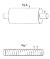
- Fig 6 is a partial perspective view of one embodiment of a torsion bar according to the present invention;
- Fig 7 is a partial perspective view of another embodiment of a torsion bar according to the present invention;
- Figs 8A and 8B are a schematic perspective views, in the direction of arrow V in Fig 2, of another embodiment of the guide members in a first condition;
- Fig 9A shows the guide members on a gas turbine engine in a first condition;
- Fig 9B show the guide members in the gas turbine engine in a second condition;
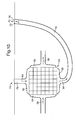
- Fig 10 is a schematic drawing of a heat exchanger incorporating adjustment arrangements according to the present invention.
- Referring to Fig. 1, a gas turbine engine is generally indicated at 10 and comprises, in axial flow series, an
air intake 11, apropulsive fan 12, anintermediate pressure compressor 13, ahigh pressure compressor 14,combustion equipment 15, ahigh pressure turbine 16, anintermediate pressure turbine 17, alow pressure turbine 18 and a variable area core exhausthot nozzle 19 and a variable areacold bypass nozzle 21. Theengine 10 is surrounded by a nacelle 9 which defines abypass duct 8 and thebypass nozzle 21. - The
gas turbine engine 10 works in a conventional manner so that air entering theintake 11 is accelerated by thefan 12 which produce two air flows: a first air flow into theintermediate pressure compressor 13 and a second air flow which provides propulsive thrust through thecold nozzle 21. The intermediate pressure compressor compresses the air flow directed into it before delivering that air to thehigh pressure compressor 14 where further compression takes place. - The compressed air exhausted from the
high pressure compressor 14 is directed into thecombustion equipment 15 where it is mixed with fuel and the mixture combusted. The resultant hot combustion products then expand through, and thereby drive, the high, intermediate andlow pressure turbines hot nozzle 19 to provide additional propulsive thrust. The high, intermediate andlow pressure turbine intermediate pressure compressors fan 12 by suitable interconnectingshafts 20. - Fig 2 shows a close up of the rear region of the
engine 10 shown in Fig 1. Fig 2 shows an outercold nozzle 22 and an innerhot nozzle 24. Gas from thefan 12 is exhausted from theengine 10 via theouter nozzle 22. Gas passing through the core of the engine, namely thecompressors combustor 15 and theturbines inner nozzle 24. The gas leaving via theinner nozzle 24 is hotter than the gas leaving theouter nozzle 22. - As can be seen from Fig 2, the
outer nozzle 22 is provided with an outer fluidflow control device 26, and theinner nozzle 24 is provided with an inner fluidflow control device 28. - Each of the fluid
flow control devices guide members 30. Figs 3, 4, 5, 8 and 9 show five embodiments of the outer fluidflow control device 26, but it will be appreciated that a similar construction is provided for theinner adjustment arrangement 28. - Referring to Fig 3, a
guide member 30 is mounted on an urging arrangement in the form of atorsion bar 32. Thetorsion bar 32 extends circumferentially around theouter nozzle 22, and a plurality of theguide members 30 are mounted thereon adjacent to one another in a circumferential sequence around thetorsion bar 32. Thetorsion bar 32 exerts an urging force F1 on theguide members 30 to urge them to a minimum area, or closed, position, as shown in Fig 2. - As an aircraft having an engine with a fixed geometry nozzle accelerates to cruise, the difference between the jet velocity and ambient decreases and the engine's efficiency reduces. With a variable area nozzle the reduction in nozzle area between take-off and cruise therefore increases jet velocity and improves engine efficiency. Between take-off and cruise there is a change in pressures of ambient, core (inner) and bypass (outer) fluids such that the relative pressures causing the forces F2 alter to thereby allow movement of the
guide members 30. - Each of the
guide members 30 of a trapezoidal configuration and tapers in the downstream direction, having athicker edge 34 adjacent thetorsion bar 32 and athinner edge 36 spaced from thetorsion bar 32. Each of theguide members 30 is fixedly mounted to thetorsion bar 32 by clampingarrangements 38. - An elongate fixing
member 40 secures thetorsion bar 32 in the region of eachguide member 30 to the main body of the nozzle. - Referring to Fig 4, the inner and outer
nozzle adjustment arrangements guide members 30 are arranged around the core (inner) and bypass (outer)nozzle torsion bars 32 and are shown projecting into the exhaust gas streams to give a minimum nozzle area configuration particularly suitable for aircraft cruise. During take-off the pressure difference is such that theguide members 30 are forced radially outwardly to increase the nozzle area. The mean velocity of the working fluid decreases, relative to a fixed geometry nozzle, thereby reducing jet noise generated in a turbulent shear layer between adjacent jets and ambient. A decrease in relative jet velocities has a corresponding decrease in jet noise. Jet noise is further reduced as vortices are generated from theguide members 30, which enhances mixing of the shear layers. - Referring to Fig 5, a minimum
area stop member 42 is provided on the radially inner side of eachguide member 30 and prevents movement of therespective guide member 30 beyond a first position, as shown in broken lines in Fig 5, to limit the minimum nozzle exit area. A respective dampingarrangement 44 is provided on the torsion bar in the region of at least some of theguide members 30 to ensure that movement of theguide member 30 occurs at the desired rate. A maximumarea stop member 45 is provided on the radially outer side of eachguide member 30 and prevents movement of therespective guide member 30 beyond a second position, as shown in solid lines in Fig 5, to limit the maximum nozzle exit area. - When the
engine 10 is in operation, the pressures inside the respective inner andouter nozzles nozzles guide members 30 as a result of the pressure differences. It will be appreciated that the pressure force F2 on theguide members 30 of the outer fluidflow control device 26 is different to the pressure force F2 or theguide members 30 of the inner fluidflow control device 28. - Similarly, the urging force F1 on the
guide members 30 of the outer fluidflow control device 26 are different to the urging force F1 on theguide members 30 of the inner fluidflow control device 28. - When the
engine 10 is running at a cruise condition, then the urging forces F1 are greater than the pressure forces F2 and there is a net force urging theguide members 30 to the minimum area, or closed, positions shown in Figs 2, 5 and 9A, where theguide members 30 engage the minimumarea stop member 42. - As the speed of the
engine 10 increases, for example at take-off, the pressure differences between the inner and outer regions A and B increases out and the net pressure forces F2 on theguide members 30 increases. As the pressure forces F2 increase, they will eventually exceed the urging forces F1 and the net forces on theguide members 30 will be in the direction indicated by the arrows X in Fig 9B towards their maximum area, or fully open, position, where the guide members engage the maximumarea stop members 45. - The torsion bars 32 have the property that the urging forces exerted thereby increase as the torsion bars are twisted away from their relaxed condition. Thus, as the torsion bars are urged in the directions of the arrows X, the urging forces F1 increase until the forces F1 equal the forces F2. As a result, the
guide members 30 can be held in any position between the maximum area positions shown in Fig 9A and the minimum area positions shown in Fig 9B. - It will be appreciated that the properties and the materials of the torsion bars 32 used for the inner and
outer adjustment arrangements respective torsion bars 32 to be used. - In one arrangement, the torsion bar is pre-stressed to bias it to one of the first or second positions. It is desirable to pre-stress the torsion bar to the maximum nozzle area position so that in the event of mechanical failure the maximum nozzle area, required at least for take-off, is available. Alternatively, it is preferable to pre-stress the torsion bar to the minimum nozzle area position to ensure efficiency during cruise.
- In one embodiment the torsion bar comprises a Shape Memory Material (SMM) such that its Young's modulus change, at its temperature transition point, assists the pressure differential change to move the
guide members 30 between their first and second positions. The torsion bar will still be pre-stressed to the first position. The SMM properties can be manipulated such that the transition point coincides with a desired altitude, for example, so that the torsion bar deforms to the second position at and above that altitude, for example where jet noise is no longer problematic. When the aircraft drops below the transition altitude the SMM torsion bar deforms back to its original configuration in the first position. Alternatively the torsion bar may be pre-stressed to the second position and transition to the first position at the desired altitude. Another parameter may be used instead of altitude. The SMM may comprise a Shape Memory Alloy as known in the art. - It should be apparent to the skilled reader that the SMM may be temperature controlled by supplying heat from a source such as electrical heating wires or from a dedicated hot air ducting, e.g. from the IP or HP compressors. The SMM torsion bar may comprise a solid bar or a hollow tube. The latter is particularly advantageous when controlled using hot air ducting since it becomes its own duct.
- Selective temperature changes to the SMM provides assistance to gas loading to move the
guide members 30. Advantageously, the stiffness of thetorsion bar 32 changes above and below the temperature transition point of the SMM, therefore enabling the gas loads to move themembers 30 more easily at certain conditions. - A further embodiment of the torsion bar is shown in Fig 6 wherein the
torsion bar 32 comprises afirst material core 46 surrounded by anSMM 48 such that thefirst material 46 and theSMM 48 are coaxially arranged. The twomaterials SMM 48 rotates the attached guide members 30 (not shown for clarity) to their deployed positions. Thefirst material 46 acts to assist the return of the arrangement to the non-deployed position when the transition point is crossed in the opposite direction thereby negating any hysteresis effects. This arrangement is advantageous because thefirst material 46 experiences lower stresses than theSMM 48, in accordance with their capacity to be stressed. It may also be possible to remove at least one of thestop members first material 46 and theSMM 48 acting in opposition to each other. - Yet a further embodiment of the torsion bar is shown in Fig 7 wherein the
torsion bar 32 comprises afirst material core 46 with a strip orwire 50 of SMM wound around thecore 46 to form a helix or coil. This arrangement provides for less stress in thetorsion bar 32. A further advantage can be realised by designing the coils ofSMM 50 to be coil bound when theguide members 30 are in the deployed position so that theSMM 50 coil itself performs the function of an end stop. Alternatively, the SMM coils 50 may be designed to be coil bound when theguide members 30 are in the non-deployed position. - Figs 8A and 8B are schematic perspective diagrams of some of the plurality of
guide members 30 in an alternative arrangement to Fig 5. This alternative arrangement comprised fixed andmoveable guide members Adjacent guide members lateral edges separate stop members Alternate guide members 30a are fixed in their alignment whilst theother guide members 30 are free to move between the first and second positions as previously described. Hence, when theguide members 30 move from the second, open position (Fig 8B) to the first, closed position (Fig 8A) the angled abuttingedges guide members - This arrangement is advantageous as the
moveable guide members 30 will form a smooth airwash surface on the nozzle, particularly useful to minimise drag at cruise. A stop member may be added to provide a positive and known rotation into the deployed / second position. - There is thus described a simple and effective adjustment arrangement for adjusting the areas of the inner and
outer nozzles engine 10. - The present invention has hereinbefore been described with reference to the nozzle or nozzles of a gas turbine engine. However, Fig 10 shows a further application of the fluid flow control device to control flow through a
heat exchanger 52 within agas turbine engine 10. Theheat exchanger 52 comprises afirst inlet 54 in fluid communication with afirst outlet 56 through which flows a first fluid as indicated byarrows 58. Theheat exchanger 52 also comprises asecond inlet 60 in fluid communication with asecond outlet 62 through which flows a second fluid as indicated byarrows 64. In use, heat exchange occurs between the first and second fluid flows 58, 64 within theheat exchanger 52. For example, thefirst flow 58 may be extracted from acompressor stage second flow 64 be extracted from thebypass duct 21 so that thefirst flow 58 is cooled by its proximity with the second,cooler flow 64. - The
second inlet 60 andsecond outlet 62 are shown in Fig 10 in fluid communication with a duct 66, for example thebypass duct 8. A first fluid flow control device 68 according to the present invention is provided at the junction of thesecond outlet 62 and the duct 66. This comprises adoor 70 attached to atorsion bar 72 and is operable in the same manner as previously described with reference to other embodiments of the present invention. Thus there is a pressure difference between the two sides of thedoor 70 which provides a pressure force F2. Thetorsion bar 72 is pre-stressed to provide an urging force F1 which opposes the pressure force F2. Thus, when the pressure of thesecond flow 64 is greater than that in the flow through the duct 66, the pressure force F2 is greater than the urging force F1 and thedoor 70 is moved to an open position in which the flow is relatively unrestricted. Conversely, when the pressure of thesecond flow 64 decreases below a predetermined value the pressure force F2 is less than the urging force F1 and thedoor 70 is moved to a closed position in which the flow is relatively restricted or blocked. - A second fluid
flow control device 74 may be provided at the junction of thesecond inlet 60 and the duct 66. This would act in the same manner as the first fluid flow control device 68; hence the two fluidflow control devices 68, 74 would move in approximate synchronicity. - Although the
second flow 64 has been described in fluid communication with the duct 66 and controlled by fluidflow control devices 68, 74 according to the present invention, thefirst flow 58 could be in fluid communication with the duct 66 instead. The fluid flow control device may be provided on any one or combination of the inlets and outlets of theheat exchanger 52. Other modifications will be obvious to the skilled reader. - Although the present invention is described as providing an fluid flow control device for the exhaust nozzles of gas turbine engines to improve fuel consumption and engine efficiency, it can equally provide noise reduction benefits by the careful selection of guide member shape and size.
GB/2,374,121/B GB 2,374,121 B - Various modifications can be made without departing from the scope of the invention. Although the above embodiments relate to a three shaft gas turbine engine, it will be appreciated that embodiments of the invention could be used on a two shaft gas turbine engine.
Claims (23)
- A fluid flow control device (26, 28) comprising a guide member (30) to guide a fluid passing through a duct (22, 24, 76), the guide member (30) being movable between first and second positions; and an urging arrangement (32) capable of providing an urging force (F1) to urge the guide member (30) towards the first position, characterised in that the urging arrangement (32) is a resilient torsion bar that is formed so as to allow the guide member (30) to be moved towards the second position by a pressure force (F2) exceeding and opposite to the urging force (F1), the pressure force (F2) being provided by a pressure difference across the guide member (30).
- A fluid flow control device (26, 28) according to claim 1 wherein the resilient torsion bar (32) is generally annular in configuration to extend around the fluid flow path.
- A fluid flow control device (26, 28) according to claim 2 wherein the assembly comprises a plurality of the guide members (30) arranged adjacent one another around the resilient torsion bar (32).
- A fluid flow control device (26, 28) according to claim 1 wherein the urging arrangement (32) comprises a plurality of resilient torsion bars (32) arranged one after the other in an annular arrangement.
- A fluid flow control device (26, 28) according to claim 4 wherein each resilient torsion bar (32) has a discrete guide member (30) mounted thereon.
- A fluid flow control device (26, 28) according to any preceding claim wherein the first position of the, or each, guide member (30) provides a minimum area condition for the fluid path, and the second position of the, or each, guide member (30) provides a maximum area of condition for the fluid path.
- A fluid flow control device (26, 28) according to any preceding claim wherein the, or each, guide member (30) comprises a tapering member tapering from a wide region adjacent the resilient torsion bar (32), to a narrow region spaced from the resilient torsion bar (32).
- A fluid flow control device (26, 28) according to any preceding claim wherein a securing arrangement (38) is provided to secure the, or each, guide member (30) to the resilient torsion bar (32).
- A fluid flow control device (26, 28) according to claim 8 wherein the securing arrangement (38) comprises a clamp.
- A fluid flow control device (26, 28) according to claim 8 wherein the securing arrangement (38) comprises first and second clamps.
- A fluid flow control device (26, 28) according to any preceding claim wherein a conduit (22, 24) defines the fluid flow path, and a fixing element (40) is provided to fix the fluid flow control device to the conduit (22, 24), the fixing element (40) extending in an upstream direction from the resilient torsion bar (32) fixing to the conduit (22, 24) .
- A fluid flow control device (26, 28) according to any preceding claim wherein a first stop (42) is provided to restrict the extent of movement of the, or each, guide member (30) when urged towards the first position and to provide a minimum area of the fluid path, and a second stop (45) is provided to restrict the extent of travel of the, or each, guide member (30) when being urged towards the second position, and to provide a maximum area of the fluid path.
- A fluid flow control device (26, 28) according to any preceding claim wherein damping arrangement (44) is provided to inhibit the speed at which the guide member (30) moves between the first and second positions.
- A fluid flow control device (26, 28) according to any preceding claim wherein the resilient torsion bar (32) comprises a Shape Memory Material.
- A fluid flow control device (26, 28) according to any preceding claim wherein the assembly comprises fixed and moveable guide members (30a, 30).
- A fluid flow control device (26, 28) according to claim 15 wherein the fixed and moveable guide members (30a, 30) are alternately spaced to one another.
- A fluid flow control device (26, 28) according to claim 15 or claim 16 wherein the guide members (30, 30a) have lateral edges (131, 132) that are angled to abut one another to provide positive location in the first or second position.
- A nozzle arrangement (22, 24) comprising a nozzle (22, 24) though which a fluid can flow, the nozzle (22, 24) having an outlet, and the arrangement further comprising a fluid flow control device (26, 28) as claimed in any preceding claim arranged on the nozzle (22, 24) at the outlet.
- A nozzle arrangement (22, 24) according to claim 18 when dependent on any claim except claim 4 or claim 5 wherein the nozzle arrangement (22, 24) comprises a plurality of guide members (30) arranged circumferentially around the outlet of the nozzle (22, 24), each guide member (30) being mounted on a common resilient torsion bar (32), which extends around the nozzle (22, 24).
- A nozzle arrangement (22, 24) according to claim 18 when dependent on any claim except claim 2 comprising a plurality of guide members (30) arranged adjacent one another around the resilient torsion bar (32), the nozzle arrangement (22, 24) comprising a plurality of discrete guide members (30) arranged on respective discrete resilient torsion bars (32).
- A nozzle arrangement (22, 24) according to claim 20 wherein a plurality of the aforesaid discrete guide members (30) and respective discrete resilient torsion bars (32) are circumferentially arranged adjacent one another.
- A heat exchanger (52) comprising a first inlet (54), a first outlet (56), a second inlet (60) and a second outlet (62) wherein at least one of the inlets and outlets comprises a fluid flow control device (68, 74) as claimed in claim 1.
- A gas turbine engine comprising a fan for directing a first flow of air through a first nozzle (22), and a turbine arrangement for directing a second flow of air through a second nozzle (24), a first fluid flow control device (26) as claimed in claim 1 or 2 provided on the first nozzle (22), and a second fluid flow control device (28) as claimed in any of claims 1 to 17 provided on the second nozzle (24).
Applications Claiming Priority (1)
| Application Number | Priority Date | Filing Date | Title |
|---|---|---|---|
| GB0606823A GB0606823D0 (en) | 2006-04-05 | 2006-04-05 | Adjustment assembly |
Publications (3)
| Publication Number | Publication Date |
|---|---|
| EP1843030A2 true EP1843030A2 (en) | 2007-10-10 |
| EP1843030A3 EP1843030A3 (en) | 2011-02-23 |
| EP1843030B1 EP1843030B1 (en) | 2015-09-16 |
Family
ID=36539349
Family Applications (1)
| Application Number | Title | Priority Date | Filing Date |
|---|---|---|---|
| EP07250953.2A Ceased EP1843030B1 (en) | 2006-04-05 | 2007-03-07 | Flow control device |
Country Status (3)
| Country | Link |
|---|---|
| US (1) | US8122723B2 (en) |
| EP (1) | EP1843030B1 (en) |
| GB (1) | GB0606823D0 (en) |
Cited By (3)
| Publication number | Priority date | Publication date | Assignee | Title |
|---|---|---|---|---|
| WO2008045064A1 (en) * | 2006-10-12 | 2008-04-17 | United Technologies Corporation | Turbofan engine sound control system and method |
| EP2455584A1 (en) * | 2010-11-19 | 2012-05-23 | Alstom Technology Ltd | Gasturbine comprising cooling control means which are made partially of Shape Memory Materials (SMM) |
| EP2074310B1 (en) * | 2006-10-12 | 2015-06-17 | United Technologies Corporation | Controlling the aerodynamic drag of a gas turbine engine during a shutdown state |
Families Citing this family (10)
| Publication number | Priority date | Publication date | Assignee | Title |
|---|---|---|---|---|
| GB0505246D0 (en) * | 2005-03-15 | 2005-04-20 | Rolls Royce Plc | Engine noise |
| US7963099B2 (en) * | 2007-05-21 | 2011-06-21 | General Electric Company | Fluted chevron exhaust nozzle |
| FR2928183A1 (en) * | 2008-02-29 | 2009-09-04 | Aircelle Sa | NOISE REDUCTION DEVICE FOR AN AIRCRAFT ENGINE OF THE MOBILE CHEVRONS TYPE |
| FR2934875B1 (en) * | 2008-08-06 | 2010-08-13 | Aircelle Sa | NACELLE OF TURBOREACTEUR MOBILE CHEVRONS. |
| US8910465B2 (en) | 2009-12-31 | 2014-12-16 | Rolls-Royce North American Technologies, Inc. | Gas turbine engine and heat exchange system |
| US10329945B2 (en) * | 2015-04-21 | 2019-06-25 | Siemens Energy, Inc. | High performance robust gas turbine exhaust with variable (adaptive) exhaust diffuser geometry |
| GB201718796D0 (en) | 2017-11-14 | 2017-12-27 | Rolls Royce Plc | Gas turbine engine having an air-oil heat exchanger |
| US11286881B2 (en) * | 2019-10-16 | 2022-03-29 | Rolls-Royce North American Technologies Inc. | Gas turbine engine with reversible heat exchanger |
| US11492998B2 (en) * | 2019-12-19 | 2022-11-08 | The Boeing Company | Flexible aft cowls for aircraft |
| US11724815B2 (en) * | 2021-01-15 | 2023-08-15 | The Boeing Company | Hybrid electric hydrogen fuel cell engine |
Family Cites Families (18)
| Publication number | Priority date | Publication date | Assignee | Title |
|---|---|---|---|---|
| US2457936A (en) * | 1945-03-21 | 1949-01-04 | Edward A Stalker | Jet-powered lifting rotor for rotary wing aircraft |
| US2569497A (en) * | 1948-10-07 | 1951-10-02 | Ervin E Schiesel | Combined variable area nozzle and after-burner control for jet motors |
| US2997845A (en) * | 1957-03-22 | 1961-08-29 | Rolls Royce | Jet propulsion nozzle adjustable to give forward and reverse thrusts |
| GB862477A (en) * | 1957-06-12 | 1961-03-08 | Hunting Aircraft Ltd | Improvements in variable area nozzle orifices |
| US2938335A (en) * | 1958-04-14 | 1960-05-31 | Boeing Co | Noise suppressor and thrust reverser |
| US3027714A (en) * | 1959-06-11 | 1962-04-03 | Canadair Ltd | Combined thrust reversing and noise suppressing device for turbo-jet engines |
| US3367579A (en) | 1965-12-08 | 1968-02-06 | Air Force Usa | Supersonic convergent-divergent jet exhaust nozzle |
| DE2158625A1 (en) * | 1971-11-26 | 1973-05-30 | Messerschmitt Boelkow Blohm | THROTTLE NOZZLE FOR JET ENGINES |
| DE3542762A1 (en) * | 1985-12-04 | 1987-06-11 | Mtu Muenchen Gmbh | DEVICE FOR CONTROLLING OR CONTROLLING GAS TURBINE ENGINES OR GAS TURBINE JET ENGINES |
| US5941065A (en) * | 1996-11-04 | 1999-08-24 | The Boeing Company | Stowable mixer ejection nozzle |
| FR2757571B1 (en) * | 1996-12-24 | 2003-03-28 | Europ Propulsion | DEPLOYABLE DIVERGENT FOR PROPELLER |
| GB9825651D0 (en) * | 1998-11-23 | 1999-01-13 | Lucas Ind Plc | Actuator |
| GB0105349D0 (en) * | 2001-03-03 | 2001-04-18 | Rolls Royce Plc | Gas turbine engine exhaust nozzle |
| US6966175B2 (en) * | 2003-05-09 | 2005-11-22 | The Nordam Group, Inc. | Rotary adjustable exhaust nozzle |
| US7264203B2 (en) * | 2003-10-02 | 2007-09-04 | The Nordam Group, Inc. | Spider actuated thrust reverser |
| US7216831B2 (en) * | 2004-11-12 | 2007-05-15 | The Boeing Company | Shape changing structure |
| US7546727B2 (en) * | 2004-11-12 | 2009-06-16 | The Boeing Company | Reduced noise jet engine |
| US7568348B2 (en) * | 2005-11-28 | 2009-08-04 | Aerojet-General Corporation | Nozzle assembly for rocket and ramjet applications |
-
2006
- 2006-04-05 GB GB0606823A patent/GB0606823D0/en not_active Ceased
-
2007
- 2007-03-07 EP EP07250953.2A patent/EP1843030B1/en not_active Ceased
- 2007-03-08 US US11/715,343 patent/US8122723B2/en not_active Expired - Fee Related
Cited By (7)
| Publication number | Priority date | Publication date | Assignee | Title |
|---|---|---|---|---|
| WO2008045064A1 (en) * | 2006-10-12 | 2008-04-17 | United Technologies Corporation | Turbofan engine sound control system and method |
| US8313285B2 (en) | 2006-10-12 | 2012-11-20 | United Technologies Corporation | Variable area nozzle assisted noise control of a gas turbine engine |
| EP2074310B1 (en) * | 2006-10-12 | 2015-06-17 | United Technologies Corporation | Controlling the aerodynamic drag of a gas turbine engine during a shutdown state |
| EP3591202A1 (en) * | 2006-10-12 | 2020-01-08 | United Technologies Corporation | Turbofan engine sound control system and method |
| EP2455584A1 (en) * | 2010-11-19 | 2012-05-23 | Alstom Technology Ltd | Gasturbine comprising cooling control means which are made partially of Shape Memory Materials (SMM) |
| CH704124A1 (en) * | 2010-11-19 | 2012-05-31 | Alstom Technology Ltd | Rotating machine, in particular gas turbine. |
| US9267382B2 (en) | 2010-11-19 | 2016-02-23 | Alstom Technology Ltd | Rotating machine |
Also Published As
| Publication number | Publication date |
|---|---|
| GB0606823D0 (en) | 2006-05-17 |
| US20070235080A1 (en) | 2007-10-11 |
| EP1843030A3 (en) | 2011-02-23 |
| EP1843030B1 (en) | 2015-09-16 |
| US8122723B2 (en) | 2012-02-28 |
Similar Documents
| Publication | Publication Date | Title |
|---|---|---|
| US8122723B2 (en) | Adjustment assembly | |
| US7578132B2 (en) | Gas turbine engine exhaust nozzle | |
| EP3969730B1 (en) | Multi-mode heat rejection system | |
| US7093423B2 (en) | Methods and apparatus for operating gas turbine engines | |
| EP3181868B1 (en) | Control cooling air by heat exchanger bypass | |
| US6813877B2 (en) | Gas turbine engine exhaust nozzle having a noise attenuation device driven by shape memory material actuators | |
| US8291710B2 (en) | Gas turbine engine exhaust nozzle having a composite article having a shape memory material member | |
| EP1809890B1 (en) | System for controlling a position of jet engine exhaust mixing tabs and corresponding method for varying said position | |
| EP3330517B1 (en) | Gas turbine engine with intercooled cooling air and controlled boost compressor | |
| EP2660431B1 (en) | Gas turbomachine including a counter-flow cooling system and method | |
| CN108930557B (en) | Method and system for auxiliary guide vanes at the leading edge of compressor guide vanes | |
| EP2333282A2 (en) | Variable area fan nozzle stiffeners and placement | |
| EP3232008A1 (en) | Aerofoil body | |
| EP2730773A2 (en) | A gas turbine engine exhaust nozzle | |
| US9222409B2 (en) | Aerospace engine with augmenting turbojet | |
| EP3214289B1 (en) | Heat exchanger for gas turbine engine | |
| US3386658A (en) | Convergent-divergent jet exhaust nozzle for supersonic aircraft | |
| EP3287623B1 (en) | Variable speed boost compressor for gas turbine engine cooling air supply | |
| EP3163053A1 (en) | Bleed valve arrangement for a gas turbine engine | |
| US8500399B2 (en) | Method and apparatus for enhancing compressor performance | |
| GB2537742A (en) | Convergent-divergent nozzle | |
| US8205434B2 (en) | Joint for a shape memory material | |
| EP3199779B1 (en) | Cooling air for variable geometry turbine | |
| EP2020570A2 (en) | Valveless pulse combustor | |
| EP3260694A1 (en) | Gas turbine exhaust cooling system |
Legal Events
| Date | Code | Title | Description |
|---|---|---|---|
| PUAI | Public reference made under article 153(3) epc to a published international application that has entered the european phase |
Free format text: ORIGINAL CODE: 0009012 |
|
| AK | Designated contracting states |
Kind code of ref document: A2 Designated state(s): AT BE BG CH CY CZ DE DK EE ES FI FR GB GR HU IE IS IT LI LT LU LV MC MT NL PL PT RO SE SI SK TR |
|
| AX | Request for extension of the european patent |
Extension state: AL BA HR MK YU |
|
| PUAL | Search report despatched |
Free format text: ORIGINAL CODE: 0009013 |
|
| AK | Designated contracting states |
Kind code of ref document: A3 Designated state(s): AT BE BG CH CY CZ DE DK EE ES FI FR GB GR HU IE IS IT LI LT LU LV MC MT NL PL PT RO SE SI SK TR |
|
| AX | Request for extension of the european patent |
Extension state: AL BA HR MK RS |
|
| 17P | Request for examination filed |
Effective date: 20110817 |
|
| AKX | Designation fees paid |
Designated state(s): DE ES FR GB |
|
| 17Q | First examination report despatched |
Effective date: 20140303 |
|
| GRAP | Despatch of communication of intention to grant a patent |
Free format text: ORIGINAL CODE: EPIDOSNIGR1 |
|
| INTG | Intention to grant announced |
Effective date: 20150701 |
|
| RAP1 | Party data changed (applicant data changed or rights of an application transferred) |
Owner name: ROLLS-ROYCE PLC |
|
| GRAR | Information related to intention to grant a patent recorded |
Free format text: ORIGINAL CODE: EPIDOSNIGR71 |
|
| GRAS | Grant fee paid |
Free format text: ORIGINAL CODE: EPIDOSNIGR3 |
|
| GRAA | (expected) grant |
Free format text: ORIGINAL CODE: 0009210 |
|
| INTG | Intention to grant announced |
Effective date: 20150804 |
|
| AK | Designated contracting states |
Kind code of ref document: B1 Designated state(s): DE ES FR GB |
|
| REG | Reference to a national code |
Ref country code: GB Ref legal event code: FG4D |
|
| REG | Reference to a national code |
Ref country code: DE Ref legal event code: R096 Ref document number: 602007043125 Country of ref document: DE |
|
| REG | Reference to a national code |
Ref country code: FR Ref legal event code: PLFP Year of fee payment: 10 |
|
| PG25 | Lapsed in a contracting state [announced via postgrant information from national office to epo] |
Ref country code: ES Free format text: LAPSE BECAUSE OF FAILURE TO SUBMIT A TRANSLATION OF THE DESCRIPTION OR TO PAY THE FEE WITHIN THE PRESCRIBED TIME-LIMIT Effective date: 20150916 |
|
| REG | Reference to a national code |
Ref country code: DE Ref legal event code: R082 Ref document number: 602007043125 Country of ref document: DE Representative=s name: HERNANDEZ, YORCK, DIPL.-ING., DE |
|
| REG | Reference to a national code |
Ref country code: DE Ref legal event code: R097 Ref document number: 602007043125 Country of ref document: DE |
|
| PLBE | No opposition filed within time limit |
Free format text: ORIGINAL CODE: 0009261 |
|
| STAA | Information on the status of an ep patent application or granted ep patent |
Free format text: STATUS: NO OPPOSITION FILED WITHIN TIME LIMIT |
|
| 26N | No opposition filed |
Effective date: 20160617 |
|
| REG | Reference to a national code |
Ref country code: FR Ref legal event code: PLFP Year of fee payment: 11 |
|
| REG | Reference to a national code |
Ref country code: FR Ref legal event code: PLFP Year of fee payment: 12 |
|
| PGFP | Annual fee paid to national office [announced via postgrant information from national office to epo] |
Ref country code: DE Payment date: 20200327 Year of fee payment: 14 Ref country code: GB Payment date: 20200327 Year of fee payment: 14 |
|
| PGFP | Annual fee paid to national office [announced via postgrant information from national office to epo] |
Ref country code: FR Payment date: 20200325 Year of fee payment: 14 |
|
| REG | Reference to a national code |
Ref country code: DE Ref legal event code: R119 Ref document number: 602007043125 Country of ref document: DE |
|
| GBPC | Gb: european patent ceased through non-payment of renewal fee |
Effective date: 20210307 |
|
| PG25 | Lapsed in a contracting state [announced via postgrant information from national office to epo] |
Ref country code: GB Free format text: LAPSE BECAUSE OF NON-PAYMENT OF DUE FEES Effective date: 20210307 Ref country code: FR Free format text: LAPSE BECAUSE OF NON-PAYMENT OF DUE FEES Effective date: 20210331 Ref country code: DE Free format text: LAPSE BECAUSE OF NON-PAYMENT OF DUE FEES Effective date: 20211001 |