EP1843024A1 - Power train control method and system - Google Patents
Power train control method and system Download PDFInfo
- Publication number
- EP1843024A1 EP1843024A1 EP06425240A EP06425240A EP1843024A1 EP 1843024 A1 EP1843024 A1 EP 1843024A1 EP 06425240 A EP06425240 A EP 06425240A EP 06425240 A EP06425240 A EP 06425240A EP 1843024 A1 EP1843024 A1 EP 1843024A1
- Authority
- EP
- European Patent Office
- Prior art keywords
- power train
- intensity
- engine
- pressure waves
- control unit
- Prior art date
- Legal status (The legal status is an assumption and is not a legal conclusion. Google has not performed a legal analysis and makes no representation as to the accuracy of the status listed.)
- Granted
Links
Images

Classifications
-
- F—MECHANICAL ENGINEERING; LIGHTING; HEATING; WEAPONS; BLASTING
- F02—COMBUSTION ENGINES; HOT-GAS OR COMBUSTION-PRODUCT ENGINE PLANTS
- F02D—CONTROLLING COMBUSTION ENGINES
- F02D41/00—Electrical control of supply of combustible mixture or its constituents
- F02D41/02—Circuit arrangements for generating control signals
- F02D41/14—Introducing closed-loop corrections
- F02D41/1497—With detection of the mechanical response of the engine
-
- F—MECHANICAL ENGINEERING; LIGHTING; HEATING; WEAPONS; BLASTING
- F02—COMBUSTION ENGINES; HOT-GAS OR COMBUSTION-PRODUCT ENGINE PLANTS
- F02D—CONTROLLING COMBUSTION ENGINES
- F02D2200/00—Input parameters for engine control
- F02D2200/02—Input parameters for engine control the parameters being related to the engine
- F02D2200/025—Engine noise, e.g. determined by using an acoustic sensor
-
- F—MECHANICAL ENGINEERING; LIGHTING; HEATING; WEAPONS; BLASTING
- F02—COMBUSTION ENGINES; HOT-GAS OR COMBUSTION-PRODUCT ENGINE PLANTS
- F02D—CONTROLLING COMBUSTION ENGINES
- F02D35/00—Controlling engines, dependent on conditions exterior or interior to engines, not otherwise provided for
- F02D35/02—Controlling engines, dependent on conditions exterior or interior to engines, not otherwise provided for on interior conditions
Definitions
- the present invention relates to a power train control method and system.
- the present invention may be used to advantage in a power train comprising an internal combustion engine, to which the following description refers purely by way of example.
- ECU electronice control unit
- various power train operating parameters e.g. drive shaft angular position and rotation speed
- Optimum control of power train performance by the control system calls for measuring various power train parameters which are extremely complicated and expensive to measure (such as the rotation speed of a turbosupercharger).
- certain power train parameters such as turbosupercharger rotation speed
- Number 1 in Figure 1 indicates as a whole a power train for a road vehicle (not shown).
- Power train 1 comprises an internal combustion engine 2 with four cylinders 3 (only one shown in Figure 1), each of which is connected to an intake manifold 4 by an intake pipe 5 regulated by at least one intake valve 6, and is connected to an exhaust manifold 7 by an exhaust pipe 8 regulated by at least one exhaust valve 9.
- Intake manifold 4 is supplied with fresh air (i.e. air from outside) via a throttle valve 10 adjustable between a closed position and a fully-open position.
- An exhaust device 11 with one or more catalysts extends from exhaust manifold 7 to expel the gases produced by combustion inside cylinders 3 into the atmosphere.
- a turbosupercharger (not shown) may be provided downstream from exhaust manifold 7 and upstream from intake manifold 4, to exploit the kinetic energy of the exhaust gas to increase the speed and pressure of the fresh air intake through intake manifold 4.
- Four injectors 12 are fitted to intake pipes 5 to inject petrol cyclically into intake pipes 5; and four spark plugs 13 (one for each cylinder 3) are fitted to cylinders 3 to cyclically ignite the mixture inside cylinders 3.
- Each cylinder 3 has a piston 14, which slides linearly along cylinder 3 and is connected mechanically by a connecting rod 16 to a drive shaft 15, in turn connected mechanically to a transmission 17 with the interposition of a clutch 18 to transmit drive torque to the drive wheels of the vehicle (not shown).
- Power train 1 comprises a control system 19 for monitoring operation of power train 1.
- Control system 19 comprises at least one electronic control unit 20 (ECU) which monitors operation of power train 1, is located close to engine 2, and is normally housed inside the engine compartment of the vehicle (not shown); and a number of sensors 21 connected to control unit 20 to measure various operating parameters of power train 1 (e.g. the angular position and rotation speed of drive shaft 15) which are used by control unit 20 to control power train 1.
- ECU electronice control unit 20
- sensors 21 connected to control unit 20 to measure various operating parameters of power train 1 (e.g. the angular position and rotation speed of drive shaft 15) which are used by control unit 20 to control power train 1.
- engine 2 comprises an engine block 22 containing the rotary members and comprising a crankcase 23 and a cylinder head 23 in which the four cylinders 3 are formed.
- control unit 20 is housed inside the engine compartment, close to engine block 22, and is therefore physically separate from engine block 22.
- At least one acoustic pressure sensor 21a is housed in control unit 20 (and therefore physically separate from engine block 22) to determine the intensity of pressure waves generated by power train 1, and as a function of which control unit 20 determines the value of at least one operating parameter of power train 1. More specifically, as a function of the intensity of the pressure waves generated by power train 1, control unit 20 determines the speed of rotary members of power train 1 (e.g. turbosupercharger, drive shaft 15, camshaft, and primary and secondary shaft of transmission 17) as well as combustion phenomena (e.g. detonation phenomena) inside cylinders 3 of engine 2.
- rotary members of power train 1 e.g. turbosupercharger, drive shaft 15, camshaft, and primary and secondary shaft of transmission 17
- combustion phenomena e.g. detonation phenomena
- Processing the intensity of the pressure waves generated by power train 1 to determine the value of at least one operating parameter of power train 1 comprises processing the intensity of the pressure waves in frequency, and may comprise combining the intensity of the pressure waves with signals (e.g. temperature, vibration, or instantaneous speed signals) from other sensors 21.
- signals e.g. temperature, vibration, or instantaneous speed signals
- At least one pressure sensor 21a is incorporated in control unit 20, and therefore outside engine block 22, to gather physical evidence concerning the operation of power train 1, with no direct connection (piping or contact) to engine block 22, but by gathering pressure waves (and therefore also acoustic noise, even in the non-audible range).
- the purpose of pressure sensor 21a is to extract operating quantities representing phenomena occurring in engine 2 or transmission 17, e.g. turbosupercharger rotation speed, the rotation speed of drive shaft 15, the rotation speed of a secondary shaft of transmission 17 (from which the engaged gear can be determined), and combustion status (e.g. detonation phenomena).
- control unit 20 is subject to no mechanical or thermal stress, and need not be any particular shape or size (so that space can easily be found for sensor 21a).
- control unit 20 being subject to no mechanical or thermal stress, sensor 21a incorporated in control unit 20 may be simple in design yet highly reliable.
Landscapes
- Engineering & Computer Science (AREA)
- Chemical & Material Sciences (AREA)
- Combustion & Propulsion (AREA)
- Mechanical Engineering (AREA)
- General Engineering & Computer Science (AREA)
- Supercharger (AREA)
- Combined Controls Of Internal Combustion Engines (AREA)
- Control Of Vehicle Engines Or Engines For Specific Uses (AREA)
- Control Of Electric Motors In General (AREA)
Abstract
Description
- The present invention relates to a power train control method and system.
- The present invention may be used to advantage in a power train comprising an internal combustion engine, to which the following description refers purely by way of example.
- The control system of a power train comprising an internal combustion engine comprises at least one electronic control unit (ECU) located close to the engine and normally housed in the engine compartment of a vehicle; and a number of sensors connected to the control unit to measure various power train operating parameters (e.g. drive shaft angular position and rotation speed) which are used by the control unit to control the power train.
- Optimum control of power train performance by the control system calls for measuring various power train parameters which are extremely complicated and expensive to measure (such as the rotation speed of a turbosupercharger). In other words, certain power train parameters (such as turbosupercharger rotation speed) can only be measured accurately using either laboratory instruments (which are extremely accurate but obviously unfeasible in a mass production context, for reasons of cost, size, and dependability) or invasive, extremely high-cost, potentially unreliable sensors.
- It is an object of the present invention to provide a power train control method and system designed to eliminate the aforementioned drawbacks, and which are straightforward and cheap to implement.
- According to the present invention, there are provided a power train control method and system as claimed in the accompanying Claims.
- A non-limiting embodiment of the present invention will be described by way of example with reference to the accompanying drawings, in which:
- Figure 1 shows a schematic view of a power train featuring a control system in accordance with the present invention;
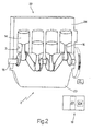
- Figure 2 shows a schematic view in perspective, with parts removed for clarity, of an internal combustion engine of the Figure 1 power train.
- Number 1 in Figure 1 indicates as a whole a power train for a road vehicle (not shown).
- Power train 1 comprises an
internal combustion engine 2 with four cylinders 3 (only one shown in Figure 1), each of which is connected to an intake manifold 4 by anintake pipe 5 regulated by at least one intake valve 6, and is connected to an exhaust manifold 7 by anexhaust pipe 8 regulated by at least one exhaust valve 9. - Intake manifold 4 is supplied with fresh air (i.e. air from outside) via a
throttle valve 10 adjustable between a closed position and a fully-open position. Anexhaust device 11 with one or more catalysts (not shown in detail) extends from exhaust manifold 7 to expel the gases produced by combustion insidecylinders 3 into the atmosphere. A turbosupercharger (not shown) may be provided downstream from exhaust manifold 7 and upstream from intake manifold 4, to exploit the kinetic energy of the exhaust gas to increase the speed and pressure of the fresh air intake through intake manifold 4. - Four injectors 12 (one for each cylinder 3) are fitted to intake
pipes 5 to inject petrol cyclically intointake pipes 5; and four spark plugs 13 (one for each cylinder 3) are fitted tocylinders 3 to cyclically ignite the mixture insidecylinders 3. - Each
cylinder 3 has apiston 14, which slides linearly alongcylinder 3 and is connected mechanically by a connectingrod 16 to adrive shaft 15, in turn connected mechanically to atransmission 17 with the interposition of aclutch 18 to transmit drive torque to the drive wheels of the vehicle (not shown). - Power train 1 comprises a
control system 19 for monitoring operation of power train 1.Control system 19 comprises at least one electronic control unit 20 (ECU) which monitors operation of power train 1, is located close toengine 2, and is normally housed inside the engine compartment of the vehicle (not shown); and a number ofsensors 21 connected tocontrol unit 20 to measure various operating parameters of power train 1 (e.g. the angular position and rotation speed of drive shaft 15) which are used bycontrol unit 20 to control power train 1. - As shown in Figure 2,
engine 2 comprises anengine block 22 containing the rotary members and comprising acrankcase 23 and acylinder head 23 in which the fourcylinders 3 are formed. It should be pointed out thatcontrol unit 20 is housed inside the engine compartment, close toengine block 22, and is therefore physically separate fromengine block 22. - As shown in Figures 1 and 2, at least one
acoustic pressure sensor 21a is housed in control unit 20 (and therefore physically separate from engine block 22) to determine the intensity of pressure waves generated by power train 1, and as a function of whichcontrol unit 20 determines the value of at least one operating parameter of power train 1. More specifically, as a function of the intensity of the pressure waves generated by power train 1,control unit 20 determines the speed of rotary members of power train 1 (e.g. turbosupercharger,drive shaft 15, camshaft, and primary and secondary shaft of transmission 17) as well as combustion phenomena (e.g. detonation phenomena) insidecylinders 3 ofengine 2. - Processing the intensity of the pressure waves generated by power train 1 to determine the value of at least one operating parameter of power train 1 comprises processing the intensity of the pressure waves in frequency, and may comprise combining the intensity of the pressure waves with signals (e.g. temperature, vibration, or instantaneous speed signals) from
other sensors 21. - In other words, at least one
pressure sensor 21a is incorporated incontrol unit 20, and therefore outsideengine block 22, to gather physical evidence concerning the operation of power train 1, with no direct connection (piping or contact) toengine block 22, but by gathering pressure waves (and therefore also acoustic noise, even in the non-audible range). The purpose ofpressure sensor 21a is to extract operating quantities representing phenomena occurring inengine 2 ortransmission 17, e.g. turbosupercharger rotation speed, the rotation speed ofdrive shaft 15, the rotation speed of a secondary shaft of transmission 17 (from which the engaged gear can be determined), and combustion status (e.g. detonation phenomena). -
Sensor 21a is cheap and easy to use, by being installable with no difficulty whatsoever insidecontrol unit 20. In this connection, it should be pointed out that, being separate fromengine block 22,control unit 20 is subject to no mechanical or thermal stress, and need not be any particular shape or size (so that space can easily be found forsensor 21a). Moreover,control unit 20 being subject to no mechanical or thermal stress,sensor 21a incorporated incontrol unit 20 may be simple in design yet highly reliable.
Claims (16)
- A control method for controlling an internal combustion power train (1) comprising an engine (2) having an engine block (22) containing the rotary members; the control method comprising the steps of:measuring the values of various operating parameters of the power train (1) by means of a number of sensors (21); andmonitoring operation of the engine (2) using the values of the operating parameters of the power train (1) by means of at least one control unit (20), which is physically separate from the engine block (22) and connected to the sensors (21);the control method being characterized by comprising the further steps of:determining the intensity of pressure waves generated by the power train (1), by means of at least one pressure sensor (21a) housed in the control unit (20) and physically separate from the engine block (22); anddetermining, by means of the control unit (20), the value of at least one operating parameter of the power train (1) as a function of the intensity of the pressure waves generated by the power train (1).
- A control method as claimed in Claim 1, wherein the speed of rotary members of the power train (1) is determined as a function of the intensity of the pressure waves generated by the power train (1).
- A control method as claimed in Claim 1 or 2, wherein the engine (2) is an internal combustion engine, and the engine block (22) comprises a crankcase (23), and a cylinder head (22) in which a number of cylinders (3) are formed.
- A control method as claimed in Claim 3, wherein combustion phenomena inside the cylinders (3) of the engine (2) are determined as a function of the intensity of the pressure waves generated by the power train (1).
- A control method as claimed in Claim 4, wherein detonation phenomena inside the cylinders (3) of the engine (2) are determined as a function of the intensity of the pressure waves generated by the power train (1).
- A control method as claimed in one of Claims 1 to 5, wherein the pressure sensor (21a) is an acoustic sensor.
- A control method as claimed in one of Claims 1 to 6, wherein processing the intensity of the pressure waves generated by the power train (1) to determine the value of at least one operating parameter of the power train (1) comprises processing the intensity of the pressure waves in frequency.
- A control method as claimed in one of Claims 1 to 7, wherein processing the intensity of the pressure waves generated by the power train (1) to determine the value of at least one operating parameter of the power train (1) comprises combining the intensity of the pressure waves with signals from other sensors (21).
- A control system (19) for controlling an internal combustion power train (1) comprising an engine (2) having an engine block (22) containing the rotary members;the control system (19) comprising at least one control unit (20) physically separate from the engine block (22) and which monitors operation of the engine (2); and a number of sensors (21) connected to the control unit (20) and which measure the values of various operating parameters of the power train (1) which are used by the control unit (20) to control the power train (1) ;the control system (19) being characterized by comprising at least one pressure sensor (21a) which is housed in the control unit (20), is physically separate from the engine block (22), and determines the intensity of pressure waves generated by the power train (1); and the control unit (20) determining the value of at least one operating parameter of the power train (1) as a function of the intensity of the pressure waves generated by the power train (1).
- A control system (19) as claimed in Claim 9, wherein the control unit (20) determines the speed of rotary members of the power train (1) as a function of the intensity of the pressure waves generated by the power train (1).
- A control system (19) as claimed in Claim 9 or 10, wherein the engine (2) is an internal combustion engine, and the engine block (22) comprises a crankcase (23), and a cylinder head (22) in which a number of cylinders (3) are formed.
- A control system (19) as claimed in Claim 11, wherein the control unit (20) determines combustion phenomena inside the cylinders (3) of the engine (2) as a function of the intensity of the pressure waves generated by the power train (1).
- A control system (19) as claimed in Claim 12, wherein the control unit (20) determines detonation phenomena inside the cylinders (3) of the engine (2) as a function of the intensity of the pressure waves generated by the power train (1).
- A control system (19) as claimed in one of Claims 9 to 13, wherein the pressure sensor (21a) is an acoustic sensor.
- A control system (19) as claimed in one of Claims 9 to 14, wherein processing the intensity of the pressure waves generated by the power train (1) to determine the value of at least one operating parameter of the power train (1) comprises processing the intensity of the pressure waves in frequency.
- A control system (19) as claimed in one of Claims 9 to 15, wherein processing the intensity of the pressure waves generated by the power train (1) to determine the value of at least one operating parameter of the power train (1) comprises combining the intensity of the pressure waves with signals from other sensors (21).
Priority Applications (4)
| Application Number | Priority Date | Filing Date | Title |
|---|---|---|---|
| EP06425240.6A EP1843024B1 (en) | 2006-04-06 | 2006-04-06 | Power train control method and system |
| US11/732,907 US8155846B2 (en) | 2006-04-06 | 2007-04-04 | Power train control method and system |
| BRPI0701310-8A BRPI0701310B1 (en) | 2006-04-06 | 2007-04-05 | POWER SET METHOD AND CONTROL SYSTEM |
| CN200710090418.6A CN101050730B (en) | 2006-04-06 | 2007-04-06 | Power train control method and system |
Applications Claiming Priority (1)
| Application Number | Priority Date | Filing Date | Title |
|---|---|---|---|
| EP06425240.6A EP1843024B1 (en) | 2006-04-06 | 2006-04-06 | Power train control method and system |
Publications (2)
| Publication Number | Publication Date |
|---|---|
| EP1843024A1 true EP1843024A1 (en) | 2007-10-10 |
| EP1843024B1 EP1843024B1 (en) | 2017-07-26 |
Family
ID=36760493
Family Applications (1)
| Application Number | Title | Priority Date | Filing Date |
|---|---|---|---|
| EP06425240.6A Expired - Lifetime EP1843024B1 (en) | 2006-04-06 | 2006-04-06 | Power train control method and system |
Country Status (4)
| Country | Link |
|---|---|
| US (1) | US8155846B2 (en) |
| EP (1) | EP1843024B1 (en) |
| CN (1) | CN101050730B (en) |
| BR (1) | BRPI0701310B1 (en) |
Cited By (2)
| Publication number | Priority date | Publication date | Assignee | Title |
|---|---|---|---|---|
| EP2180178A1 (en) | 2008-10-21 | 2010-04-28 | Magneti Marelli Powertrain S.p.A. | Method of detecting knock in an internal combustion engine |
| EP3184785A1 (en) | 2015-12-23 | 2017-06-28 | Magneti Marelli S.p.A. | Device for the acquisition and conditioning of an acoustic signal generated by a source of an internal combustion engine |
Families Citing this family (1)
| Publication number | Priority date | Publication date | Assignee | Title |
|---|---|---|---|---|
| JP6541586B2 (en) * | 2016-01-22 | 2019-07-10 | 三菱重工業株式会社 | Knocking detection method, ignition timing control method and control system for internal combustion engine |
Citations (4)
| Publication number | Priority date | Publication date | Assignee | Title |
|---|---|---|---|---|
| WO2001023731A1 (en) * | 1999-09-30 | 2001-04-05 | Siemens Automotive Corporation | Integral engine control sensor |
| US20010023685A1 (en) * | 2000-03-16 | 2001-09-27 | Aisan Kogyo Kabushiki Kaisha | Air-fuel mixture control device of engine |
| DE10032931A1 (en) * | 2000-07-06 | 2002-02-07 | Atlas Fahrzeugtechnik Gmbh | Direct fuel injection type multicylinder 4-stroke internal combustion engine control method involves measuring assignment sound pressure intensities of cylinders and indending correction values for fuel injection |
| US20020095978A1 (en) * | 2000-06-16 | 2002-07-25 | Stefan Muhlberger | Method for assessing the phase angle of a camshaft of an internal combustion engine, in particular for a motor vehicle |
Family Cites Families (13)
| Publication number | Priority date | Publication date | Assignee | Title |
|---|---|---|---|---|
| DE3523017A1 (en) * | 1984-06-29 | 1986-01-02 | Nissan Motor Co., Ltd., Yokohama, Kanagawa | DEVICE AND METHOD FOR DETERMINING AND INFLUENCING THE KNOCKING OF AN INTERNAL COMBUSTION ENGINE |
| US5315954A (en) * | 1990-12-12 | 1994-05-31 | Huwood Limited | Hot bearing alarm |
| JP3167766B2 (en) * | 1991-11-29 | 2001-05-21 | 本田技研工業株式会社 | Knocking control device for internal combustion engine |
| AUPM656594A0 (en) * | 1994-06-30 | 1994-07-21 | Orbital Engine Company (Australia) Proprietary Limited | A method and apparatus relating to control of the operation of an internal combustion engine |
| US5642445A (en) * | 1995-10-31 | 1997-06-24 | The United States Of America As Represented By The Secretary Of The Navy | System for determining an interior or exterior acoustic noise level of an enclosed structure and noise reduction device incorporating such system |
| US5935189A (en) * | 1997-12-31 | 1999-08-10 | Kavlico Corporation | System and method for monitoring engine performance characteristics |
| US6434456B1 (en) * | 2000-09-07 | 2002-08-13 | Kelsey-Hayes Company | High reliability pressure sensor |
| US6546328B1 (en) * | 2001-01-03 | 2003-04-08 | Eaton Corporation | Knock and misfire detection system |
| US7021128B2 (en) * | 2002-04-29 | 2006-04-04 | Avl North America, Inc. | Misfire detection using acoustic sensors |
| US7269498B2 (en) * | 2002-07-02 | 2007-09-11 | Robert Bosch Gmbh | Method and device for controlling an internal combustion engine |
| ITBO20030055A1 (en) * | 2003-02-07 | 2004-08-08 | Magneti Marelli Powertrain Spa | METHOD FOR THE RECOGNITION OF THE MISFIRE IN PHENOMENON |
| US6845312B1 (en) * | 2003-08-14 | 2005-01-18 | Brunswick Corporation | Method for detecting engine knock |
| US7155333B1 (en) * | 2005-09-02 | 2006-12-26 | Arvin Technologies, Inc. | Method and apparatus for controlling sound of an engine by sound frequency analysis |
-
2006
- 2006-04-06 EP EP06425240.6A patent/EP1843024B1/en not_active Expired - Lifetime
-
2007
- 2007-04-04 US US11/732,907 patent/US8155846B2/en active Active
- 2007-04-05 BR BRPI0701310-8A patent/BRPI0701310B1/en not_active IP Right Cessation
- 2007-04-06 CN CN200710090418.6A patent/CN101050730B/en not_active Expired - Fee Related
Patent Citations (4)
| Publication number | Priority date | Publication date | Assignee | Title |
|---|---|---|---|---|
| WO2001023731A1 (en) * | 1999-09-30 | 2001-04-05 | Siemens Automotive Corporation | Integral engine control sensor |
| US20010023685A1 (en) * | 2000-03-16 | 2001-09-27 | Aisan Kogyo Kabushiki Kaisha | Air-fuel mixture control device of engine |
| US20020095978A1 (en) * | 2000-06-16 | 2002-07-25 | Stefan Muhlberger | Method for assessing the phase angle of a camshaft of an internal combustion engine, in particular for a motor vehicle |
| DE10032931A1 (en) * | 2000-07-06 | 2002-02-07 | Atlas Fahrzeugtechnik Gmbh | Direct fuel injection type multicylinder 4-stroke internal combustion engine control method involves measuring assignment sound pressure intensities of cylinders and indending correction values for fuel injection |
Cited By (4)
| Publication number | Priority date | Publication date | Assignee | Title |
|---|---|---|---|---|
| EP2180178A1 (en) | 2008-10-21 | 2010-04-28 | Magneti Marelli Powertrain S.p.A. | Method of detecting knock in an internal combustion engine |
| US8474308B2 (en) | 2008-10-21 | 2013-07-02 | MAGNETI MARELLI S.p.A. | Method of microphone signal controlling an internal combustion engine |
| EP3184785A1 (en) | 2015-12-23 | 2017-06-28 | Magneti Marelli S.p.A. | Device for the acquisition and conditioning of an acoustic signal generated by a source of an internal combustion engine |
| US10609478B2 (en) | 2015-12-23 | 2020-03-31 | MAGNETI MARELLI S.p.A. | Device for the acquisition and conditioning of an acoustic signal generated by a source of an internal combustion engine |
Also Published As
| Publication number | Publication date |
|---|---|
| CN101050730A (en) | 2007-10-10 |
| BRPI0701310B1 (en) | 2018-05-22 |
| BRPI0701310A (en) | 2007-12-11 |
| US8155846B2 (en) | 2012-04-10 |
| EP1843024B1 (en) | 2017-07-26 |
| CN101050730B (en) | 2012-06-27 |
| US20070294015A1 (en) | 2007-12-20 |
Similar Documents
| Publication | Publication Date | Title |
|---|---|---|
| EP2180178B1 (en) | Method of detecting knock in an internal combustion engine | |
| CN102454503B (en) | For the method and apparatus of estimated engine operating parameter | |
| WO2010005651A3 (en) | Fuel system diagnostics by analyzing engine crankshaft speed signal | |
| KR101500395B1 (en) | Method and apparatus for detecting combustion of engine by angular acceleration signal and combustion data of single cylinder | |
| CN101957266A (en) | The detection of catching fire by combustion pressure sensor | |
| KR20160126874A (en) | Knock sensor systems and methods for detection of component conditions | |
| CN105863863A (en) | Methods and systems to derive knock sensor conditions | |
| ITMI20071116A1 (en) | PROCEDURE AND CONTROL UNIT TO DETERMINE A CHARACTERISTIC SIZE OF AN ENDOTHERMAL MOTOR ON THE BASIS OF A NUMBER OF LAPS OF AN ELBOW SHAFT OF THE ENDOTHERMAL ENGINE | |
| WO2006112544A1 (en) | Misfire detection device for internal combustion engine | |
| US20120111663A1 (en) | Resonator for a dual-flow exhaust system | |
| US8155846B2 (en) | Power train control method and system | |
| CN1981124B (en) | Engine operation without cam sensor | |
| JP6767749B2 (en) | Methods and systems for determining the location of peak combustion pressure | |
| JP2013076363A (en) | Combustion state detecting device of internal combustion engine | |
| JP2017223117A (en) | Misfire detection device for internal combustion engine | |
| Taglialatela-Scafati et al. | Use of vibration signal for diagnosis and control of a four-cylinder diesel engine | |
| JP2008286335A (en) | Half clutch state determination device | |
| CN107701321A (en) | The method of the generation for the phenomenon that misfired in identification explosive motor cylinder | |
| US8813711B2 (en) | Cylinder head assembly having a drainage passage | |
| CN114544186A (en) | Engine fire diagnosis method and vehicle | |
| US8919312B2 (en) | Impact dampening tappet | |
| CN116066234A (en) | System and method for inferring engine cylinder pressure | |
| RU2019118838A (en) | Method and system for monitoring technical condition parameters of an internal combustion engine | |
| US8985077B2 (en) | Valvetrain impact absorber | |
| JP2011149293A (en) | Control device for engine with supercharger |
Legal Events
| Date | Code | Title | Description |
|---|---|---|---|
| PUAI | Public reference made under article 153(3) epc to a published international application that has entered the european phase |
Free format text: ORIGINAL CODE: 0009012 |
|
| AK | Designated contracting states |
Kind code of ref document: A1 Designated state(s): AT BE BG CH CY CZ DE DK EE ES FI FR GB GR HU IE IS IT LI LT LU LV MC NL PL PT RO SE SI SK TR |
|
| AX | Request for extension of the european patent |
Extension state: AL BA HR MK YU |
|
| RIN1 | Information on inventor provided before grant (corrected) |
Inventor name: PONTI, FABRIZIO Inventor name: DE CESARE, MATTEO Inventor name: SERRA, GABRIELE |
|
| 17P | Request for examination filed |
Effective date: 20080331 |
|
| AKX | Designation fees paid |
Designated state(s): AT BE BG CH CY CZ DE DK EE ES FI FR GB GR HU IE IS IT LI LT LU LV MC NL PL PT RO SE SI SK TR |
|
| 17Q | First examination report despatched |
Effective date: 20081204 |
|
| GRAP | Despatch of communication of intention to grant a patent |
Free format text: ORIGINAL CODE: EPIDOSNIGR1 |
|
| INTG | Intention to grant announced |
Effective date: 20170214 |
|
| RAP1 | Party data changed (applicant data changed or rights of an application transferred) |
Owner name: MAGNETI MARELLI S.P.A. |
|
| GRAS | Grant fee paid |
Free format text: ORIGINAL CODE: EPIDOSNIGR3 |
|
| GRAA | (expected) grant |
Free format text: ORIGINAL CODE: 0009210 |
|
| AK | Designated contracting states |
Kind code of ref document: B1 Designated state(s): AT BE BG CH CY CZ DE DK EE ES FI FR GB GR HU IE IS IT LI LT LU LV MC NL PL PT RO SE SI SK TR |
|
| REG | Reference to a national code |
Ref country code: GB Ref legal event code: FG4D |
|
| REG | Reference to a national code |
Ref country code: CH Ref legal event code: EP |
|
| REG | Reference to a national code |
Ref country code: AT Ref legal event code: REF Ref document number: 912614 Country of ref document: AT Kind code of ref document: T Effective date: 20170815 |
|
| REG | Reference to a national code |
Ref country code: IE Ref legal event code: FG4D |
|
| REG | Reference to a national code |
Ref country code: DE Ref legal event code: R096 Ref document number: 602006053119 Country of ref document: DE |
|
| REG | Reference to a national code |
Ref country code: NL Ref legal event code: MP Effective date: 20170726 |
|
| REG | Reference to a national code |
Ref country code: LT Ref legal event code: MG4D |
|
| REG | Reference to a national code |
Ref country code: AT Ref legal event code: MK05 Ref document number: 912614 Country of ref document: AT Kind code of ref document: T Effective date: 20170726 |
|
| PG25 | Lapsed in a contracting state [announced via postgrant information from national office to epo] |
Ref country code: SE Free format text: LAPSE BECAUSE OF FAILURE TO SUBMIT A TRANSLATION OF THE DESCRIPTION OR TO PAY THE FEE WITHIN THE PRESCRIBED TIME-LIMIT Effective date: 20170726 Ref country code: AT Free format text: LAPSE BECAUSE OF FAILURE TO SUBMIT A TRANSLATION OF THE DESCRIPTION OR TO PAY THE FEE WITHIN THE PRESCRIBED TIME-LIMIT Effective date: 20170726 Ref country code: LT Free format text: LAPSE BECAUSE OF FAILURE TO SUBMIT A TRANSLATION OF THE DESCRIPTION OR TO PAY THE FEE WITHIN THE PRESCRIBED TIME-LIMIT Effective date: 20170726 Ref country code: FI Free format text: LAPSE BECAUSE OF FAILURE TO SUBMIT A TRANSLATION OF THE DESCRIPTION OR TO PAY THE FEE WITHIN THE PRESCRIBED TIME-LIMIT Effective date: 20170726 Ref country code: NL Free format text: LAPSE BECAUSE OF FAILURE TO SUBMIT A TRANSLATION OF THE DESCRIPTION OR TO PAY THE FEE WITHIN THE PRESCRIBED TIME-LIMIT Effective date: 20170726 |
|
| PG25 | Lapsed in a contracting state [announced via postgrant information from national office to epo] |
Ref country code: PL Free format text: LAPSE BECAUSE OF FAILURE TO SUBMIT A TRANSLATION OF THE DESCRIPTION OR TO PAY THE FEE WITHIN THE PRESCRIBED TIME-LIMIT Effective date: 20170726 Ref country code: LV Free format text: LAPSE BECAUSE OF FAILURE TO SUBMIT A TRANSLATION OF THE DESCRIPTION OR TO PAY THE FEE WITHIN THE PRESCRIBED TIME-LIMIT Effective date: 20170726 Ref country code: ES Free format text: LAPSE BECAUSE OF FAILURE TO SUBMIT A TRANSLATION OF THE DESCRIPTION OR TO PAY THE FEE WITHIN THE PRESCRIBED TIME-LIMIT Effective date: 20170726 Ref country code: IS Free format text: LAPSE BECAUSE OF FAILURE TO SUBMIT A TRANSLATION OF THE DESCRIPTION OR TO PAY THE FEE WITHIN THE PRESCRIBED TIME-LIMIT Effective date: 20171126 Ref country code: GR Free format text: LAPSE BECAUSE OF FAILURE TO SUBMIT A TRANSLATION OF THE DESCRIPTION OR TO PAY THE FEE WITHIN THE PRESCRIBED TIME-LIMIT Effective date: 20171027 Ref country code: BG Free format text: LAPSE BECAUSE OF FAILURE TO SUBMIT A TRANSLATION OF THE DESCRIPTION OR TO PAY THE FEE WITHIN THE PRESCRIBED TIME-LIMIT Effective date: 20171026 |
|
| REG | Reference to a national code |
Ref country code: FR Ref legal event code: PLFP Year of fee payment: 13 |
|
| PG25 | Lapsed in a contracting state [announced via postgrant information from national office to epo] |
Ref country code: DK Free format text: LAPSE BECAUSE OF FAILURE TO SUBMIT A TRANSLATION OF THE DESCRIPTION OR TO PAY THE FEE WITHIN THE PRESCRIBED TIME-LIMIT Effective date: 20170726 Ref country code: RO Free format text: LAPSE BECAUSE OF FAILURE TO SUBMIT A TRANSLATION OF THE DESCRIPTION OR TO PAY THE FEE WITHIN THE PRESCRIBED TIME-LIMIT Effective date: 20170726 Ref country code: CZ Free format text: LAPSE BECAUSE OF FAILURE TO SUBMIT A TRANSLATION OF THE DESCRIPTION OR TO PAY THE FEE WITHIN THE PRESCRIBED TIME-LIMIT Effective date: 20170726 |
|
| REG | Reference to a national code |
Ref country code: DE Ref legal event code: R097 Ref document number: 602006053119 Country of ref document: DE |
|
| PG25 | Lapsed in a contracting state [announced via postgrant information from national office to epo] |
Ref country code: SK Free format text: LAPSE BECAUSE OF FAILURE TO SUBMIT A TRANSLATION OF THE DESCRIPTION OR TO PAY THE FEE WITHIN THE PRESCRIBED TIME-LIMIT Effective date: 20170726 Ref country code: EE Free format text: LAPSE BECAUSE OF FAILURE TO SUBMIT A TRANSLATION OF THE DESCRIPTION OR TO PAY THE FEE WITHIN THE PRESCRIBED TIME-LIMIT Effective date: 20170726 |
|
| PLBE | No opposition filed within time limit |
Free format text: ORIGINAL CODE: 0009261 |
|
| STAA | Information on the status of an ep patent application or granted ep patent |
Free format text: STATUS: NO OPPOSITION FILED WITHIN TIME LIMIT |
|
| 26N | No opposition filed |
Effective date: 20180430 |
|
| PG25 | Lapsed in a contracting state [announced via postgrant information from national office to epo] |
Ref country code: SI Free format text: LAPSE BECAUSE OF FAILURE TO SUBMIT A TRANSLATION OF THE DESCRIPTION OR TO PAY THE FEE WITHIN THE PRESCRIBED TIME-LIMIT Effective date: 20170726 |
|
| PG25 | Lapsed in a contracting state [announced via postgrant information from national office to epo] |
Ref country code: MC Free format text: LAPSE BECAUSE OF FAILURE TO SUBMIT A TRANSLATION OF THE DESCRIPTION OR TO PAY THE FEE WITHIN THE PRESCRIBED TIME-LIMIT Effective date: 20170726 |
|
| REG | Reference to a national code |
Ref country code: CH Ref legal event code: PL |
|
| REG | Reference to a national code |
Ref country code: BE Ref legal event code: MM Effective date: 20180430 |
|
| GBPC | Gb: european patent ceased through non-payment of renewal fee |
Effective date: 20180406 |
|
| REG | Reference to a national code |
Ref country code: IE Ref legal event code: MM4A |
|
| PG25 | Lapsed in a contracting state [announced via postgrant information from national office to epo] |
Ref country code: LU Free format text: LAPSE BECAUSE OF NON-PAYMENT OF DUE FEES Effective date: 20180406 |
|
| PG25 | Lapsed in a contracting state [announced via postgrant information from national office to epo] |
Ref country code: LI Free format text: LAPSE BECAUSE OF NON-PAYMENT OF DUE FEES Effective date: 20180430 Ref country code: GB Free format text: LAPSE BECAUSE OF NON-PAYMENT OF DUE FEES Effective date: 20180406 Ref country code: CH Free format text: LAPSE BECAUSE OF NON-PAYMENT OF DUE FEES Effective date: 20180430 Ref country code: BE Free format text: LAPSE BECAUSE OF NON-PAYMENT OF DUE FEES Effective date: 20180430 |
|
| PG25 | Lapsed in a contracting state [announced via postgrant information from national office to epo] |
Ref country code: IE Free format text: LAPSE BECAUSE OF NON-PAYMENT OF DUE FEES Effective date: 20180406 |
|
| PG25 | Lapsed in a contracting state [announced via postgrant information from national office to epo] |
Ref country code: TR Free format text: LAPSE BECAUSE OF FAILURE TO SUBMIT A TRANSLATION OF THE DESCRIPTION OR TO PAY THE FEE WITHIN THE PRESCRIBED TIME-LIMIT Effective date: 20170726 |
|
| PG25 | Lapsed in a contracting state [announced via postgrant information from national office to epo] |
Ref country code: PT Free format text: LAPSE BECAUSE OF FAILURE TO SUBMIT A TRANSLATION OF THE DESCRIPTION OR TO PAY THE FEE WITHIN THE PRESCRIBED TIME-LIMIT Effective date: 20170726 Ref country code: HU Free format text: LAPSE BECAUSE OF FAILURE TO SUBMIT A TRANSLATION OF THE DESCRIPTION OR TO PAY THE FEE WITHIN THE PRESCRIBED TIME-LIMIT; INVALID AB INITIO Effective date: 20060406 |
|
| PG25 | Lapsed in a contracting state [announced via postgrant information from national office to epo] |
Ref country code: CY Free format text: LAPSE BECAUSE OF FAILURE TO SUBMIT A TRANSLATION OF THE DESCRIPTION OR TO PAY THE FEE WITHIN THE PRESCRIBED TIME-LIMIT Effective date: 20170726 |
|
| PGFP | Annual fee paid to national office [announced via postgrant information from national office to epo] |
Ref country code: IT Payment date: 20240320 Year of fee payment: 19 Ref country code: FR Payment date: 20240320 Year of fee payment: 19 |
|
| PGFP | Annual fee paid to national office [announced via postgrant information from national office to epo] |
Ref country code: DE Payment date: 20240320 Year of fee payment: 19 |
|
| REG | Reference to a national code |
Ref country code: DE Ref legal event code: R119 Ref document number: 602006053119 Country of ref document: DE |
|
| PG25 | Lapsed in a contracting state [announced via postgrant information from national office to epo] |
Ref country code: DE Free format text: LAPSE BECAUSE OF NON-PAYMENT OF DUE FEES Effective date: 20251104 |
|
| PG25 | Lapsed in a contracting state [announced via postgrant information from national office to epo] |
Ref country code: FR Free format text: LAPSE BECAUSE OF NON-PAYMENT OF DUE FEES Effective date: 20250430 |
|
| PG25 | Lapsed in a contracting state [announced via postgrant information from national office to epo] |
Ref country code: IT Free format text: LAPSE BECAUSE OF NON-PAYMENT OF DUE FEES Effective date: 20250406 |