EP1842937A2 - Bond coating and thermal barrier compositions, processes for applying both, and their coated articles - Google Patents
Bond coating and thermal barrier compositions, processes for applying both, and their coated articles Download PDFInfo
- Publication number
- EP1842937A2 EP1842937A2 EP20070250080 EP07250080A EP1842937A2 EP 1842937 A2 EP1842937 A2 EP 1842937A2 EP 20070250080 EP20070250080 EP 20070250080 EP 07250080 A EP07250080 A EP 07250080A EP 1842937 A2 EP1842937 A2 EP 1842937A2
- Authority
- EP
- European Patent Office
- Prior art keywords
- layer
- bond coat
- article
- material layer
- functionally graded
- Prior art date
- Legal status (The legal status is an assumption and is not a legal conclusion. Google has not performed a legal analysis and makes no representation as to the accuracy of the status listed.)
- Granted
Links
Images

Classifications
-
- C—CHEMISTRY; METALLURGY
- C04—CEMENTS; CONCRETE; ARTIFICIAL STONE; CERAMICS; REFRACTORIES
- C04B—LIME, MAGNESIA; SLAG; CEMENTS; COMPOSITIONS THEREOF, e.g. MORTARS, CONCRETE OR LIKE BUILDING MATERIALS; ARTIFICIAL STONE; CERAMICS; REFRACTORIES; TREATMENT OF NATURAL STONE
- C04B35/00—Shaped ceramic products characterised by their composition; Ceramics compositions; Processing powders of inorganic compounds preparatory to the manufacturing of ceramic products
- C04B35/515—Shaped ceramic products characterised by their composition; Ceramics compositions; Processing powders of inorganic compounds preparatory to the manufacturing of ceramic products based on non-oxide ceramics
- C04B35/58—Shaped ceramic products characterised by their composition; Ceramics compositions; Processing powders of inorganic compounds preparatory to the manufacturing of ceramic products based on non-oxide ceramics based on borides, nitrides, i.e. nitrides, oxynitrides, carbonitrides or oxycarbonitrides or silicides
- C04B35/58085—Shaped ceramic products characterised by their composition; Ceramics compositions; Processing powders of inorganic compounds preparatory to the manufacturing of ceramic products based on non-oxide ceramics based on borides, nitrides, i.e. nitrides, oxynitrides, carbonitrides or oxycarbonitrides or silicides based on silicides
- C04B35/58092—Shaped ceramic products characterised by their composition; Ceramics compositions; Processing powders of inorganic compounds preparatory to the manufacturing of ceramic products based on non-oxide ceramics based on borides, nitrides, i.e. nitrides, oxynitrides, carbonitrides or oxycarbonitrides or silicides based on silicides based on refractory metal silicides
-
- B—PERFORMING OPERATIONS; TRANSPORTING
- B05—SPRAYING OR ATOMISING IN GENERAL; APPLYING FLUENT MATERIALS TO SURFACES, IN GENERAL
- B05D—PROCESSES FOR APPLYING FLUENT MATERIALS TO SURFACES, IN GENERAL
- B05D1/00—Processes for applying liquids or other fluent materials
- B05D1/30—Processes for applying liquids or other fluent materials performed by gravity only, i.e. flow coating
-
- B—PERFORMING OPERATIONS; TRANSPORTING
- B05—SPRAYING OR ATOMISING IN GENERAL; APPLYING FLUENT MATERIALS TO SURFACES, IN GENERAL
- B05D—PROCESSES FOR APPLYING FLUENT MATERIALS TO SURFACES, IN GENERAL
- B05D3/00—Pretreatment of surfaces to which liquids or other fluent materials are to be applied; After-treatment of applied coatings, e.g. intermediate treating of an applied coating preparatory to subsequent applications of liquids or other fluent materials
- B05D3/02—Pretreatment of surfaces to which liquids or other fluent materials are to be applied; After-treatment of applied coatings, e.g. intermediate treating of an applied coating preparatory to subsequent applications of liquids or other fluent materials by baking
-
- C—CHEMISTRY; METALLURGY
- C22—METALLURGY; FERROUS OR NON-FERROUS ALLOYS; TREATMENT OF ALLOYS OR NON-FERROUS METALS
- C22C—ALLOYS
- C22C27/00—Alloys based on rhenium or a refractory metal not mentioned in groups C22C14/00 or C22C16/00
- C22C27/04—Alloys based on tungsten or molybdenum
-
- C—CHEMISTRY; METALLURGY
- C23—COATING METALLIC MATERIAL; COATING MATERIAL WITH METALLIC MATERIAL; CHEMICAL SURFACE TREATMENT; DIFFUSION TREATMENT OF METALLIC MATERIAL; COATING BY VACUUM EVAPORATION, BY SPUTTERING, BY ION IMPLANTATION OR BY CHEMICAL VAPOUR DEPOSITION, IN GENERAL; INHIBITING CORROSION OF METALLIC MATERIAL OR INCRUSTATION IN GENERAL
- C23C—COATING METALLIC MATERIAL; COATING MATERIAL WITH METALLIC MATERIAL; SURFACE TREATMENT OF METALLIC MATERIAL BY DIFFUSION INTO THE SURFACE, BY CHEMICAL CONVERSION OR SUBSTITUTION; COATING BY VACUUM EVAPORATION, BY SPUTTERING, BY ION IMPLANTATION OR BY CHEMICAL VAPOUR DEPOSITION, IN GENERAL
- C23C26/00—Coating not provided for in groups C23C2/00 - C23C24/00
-
- C—CHEMISTRY; METALLURGY
- C23—COATING METALLIC MATERIAL; COATING MATERIAL WITH METALLIC MATERIAL; CHEMICAL SURFACE TREATMENT; DIFFUSION TREATMENT OF METALLIC MATERIAL; COATING BY VACUUM EVAPORATION, BY SPUTTERING, BY ION IMPLANTATION OR BY CHEMICAL VAPOUR DEPOSITION, IN GENERAL; INHIBITING CORROSION OF METALLIC MATERIAL OR INCRUSTATION IN GENERAL
- C23C—COATING METALLIC MATERIAL; COATING MATERIAL WITH METALLIC MATERIAL; SURFACE TREATMENT OF METALLIC MATERIAL BY DIFFUSION INTO THE SURFACE, BY CHEMICAL CONVERSION OR SUBSTITUTION; COATING BY VACUUM EVAPORATION, BY SPUTTERING, BY ION IMPLANTATION OR BY CHEMICAL VAPOUR DEPOSITION, IN GENERAL
- C23C28/00—Coating for obtaining at least two superposed coatings either by methods not provided for in a single one of groups C23C2/00 - C23C26/00 or by combinations of methods provided for in subclasses C23C and C25C or C25D
- C23C28/30—Coatings combining at least one metallic layer and at least one inorganic non-metallic layer
- C23C28/32—Coatings combining at least one metallic layer and at least one inorganic non-metallic layer including at least one pure metallic layer
- C23C28/324—Coatings combining at least one metallic layer and at least one inorganic non-metallic layer including at least one pure metallic layer with at least one metal matrix material layer comprising a mixture of at least two metals or metal phases or a metal-matrix material with hard embedded particles, e.g. WC-Me
-
- C—CHEMISTRY; METALLURGY
- C23—COATING METALLIC MATERIAL; COATING MATERIAL WITH METALLIC MATERIAL; CHEMICAL SURFACE TREATMENT; DIFFUSION TREATMENT OF METALLIC MATERIAL; COATING BY VACUUM EVAPORATION, BY SPUTTERING, BY ION IMPLANTATION OR BY CHEMICAL VAPOUR DEPOSITION, IN GENERAL; INHIBITING CORROSION OF METALLIC MATERIAL OR INCRUSTATION IN GENERAL
- C23C—COATING METALLIC MATERIAL; COATING MATERIAL WITH METALLIC MATERIAL; SURFACE TREATMENT OF METALLIC MATERIAL BY DIFFUSION INTO THE SURFACE, BY CHEMICAL CONVERSION OR SUBSTITUTION; COATING BY VACUUM EVAPORATION, BY SPUTTERING, BY ION IMPLANTATION OR BY CHEMICAL VAPOUR DEPOSITION, IN GENERAL
- C23C28/00—Coating for obtaining at least two superposed coatings either by methods not provided for in a single one of groups C23C2/00 - C23C26/00 or by combinations of methods provided for in subclasses C23C and C25C or C25D
- C23C28/30—Coatings combining at least one metallic layer and at least one inorganic non-metallic layer
- C23C28/34—Coatings combining at least one metallic layer and at least one inorganic non-metallic layer including at least one inorganic non-metallic material layer, e.g. metal carbide, nitride, boride, silicide layer and their mixtures, enamels, phosphates and sulphates
- C23C28/345—Coatings combining at least one metallic layer and at least one inorganic non-metallic layer including at least one inorganic non-metallic material layer, e.g. metal carbide, nitride, boride, silicide layer and their mixtures, enamels, phosphates and sulphates with at least one oxide layer
- C23C28/3455—Coatings combining at least one metallic layer and at least one inorganic non-metallic layer including at least one inorganic non-metallic material layer, e.g. metal carbide, nitride, boride, silicide layer and their mixtures, enamels, phosphates and sulphates with at least one oxide layer with a refractory ceramic layer, e.g. refractory metal oxide, ZrO2, rare earth oxides or a thermal barrier system comprising at least one refractory oxide layer
-
- C—CHEMISTRY; METALLURGY
- C23—COATING METALLIC MATERIAL; COATING MATERIAL WITH METALLIC MATERIAL; CHEMICAL SURFACE TREATMENT; DIFFUSION TREATMENT OF METALLIC MATERIAL; COATING BY VACUUM EVAPORATION, BY SPUTTERING, BY ION IMPLANTATION OR BY CHEMICAL VAPOUR DEPOSITION, IN GENERAL; INHIBITING CORROSION OF METALLIC MATERIAL OR INCRUSTATION IN GENERAL
- C23C—COATING METALLIC MATERIAL; COATING MATERIAL WITH METALLIC MATERIAL; SURFACE TREATMENT OF METALLIC MATERIAL BY DIFFUSION INTO THE SURFACE, BY CHEMICAL CONVERSION OR SUBSTITUTION; COATING BY VACUUM EVAPORATION, BY SPUTTERING, BY ION IMPLANTATION OR BY CHEMICAL VAPOUR DEPOSITION, IN GENERAL
- C23C28/00—Coating for obtaining at least two superposed coatings either by methods not provided for in a single one of groups C23C2/00 - C23C26/00 or by combinations of methods provided for in subclasses C23C and C25C or C25D
- C23C28/30—Coatings combining at least one metallic layer and at least one inorganic non-metallic layer
- C23C28/36—Coatings combining at least one metallic layer and at least one inorganic non-metallic layer including layers graded in composition or physical properties
-
- C—CHEMISTRY; METALLURGY
- C23—COATING METALLIC MATERIAL; COATING MATERIAL WITH METALLIC MATERIAL; CHEMICAL SURFACE TREATMENT; DIFFUSION TREATMENT OF METALLIC MATERIAL; COATING BY VACUUM EVAPORATION, BY SPUTTERING, BY ION IMPLANTATION OR BY CHEMICAL VAPOUR DEPOSITION, IN GENERAL; INHIBITING CORROSION OF METALLIC MATERIAL OR INCRUSTATION IN GENERAL
- C23C—COATING METALLIC MATERIAL; COATING MATERIAL WITH METALLIC MATERIAL; SURFACE TREATMENT OF METALLIC MATERIAL BY DIFFUSION INTO THE SURFACE, BY CHEMICAL CONVERSION OR SUBSTITUTION; COATING BY VACUUM EVAPORATION, BY SPUTTERING, BY ION IMPLANTATION OR BY CHEMICAL VAPOUR DEPOSITION, IN GENERAL
- C23C4/00—Coating by spraying the coating material in the molten state, e.g. by flame, plasma or electric discharge
- C23C4/04—Coating by spraying the coating material in the molten state, e.g. by flame, plasma or electric discharge characterised by the coating material
-
- C—CHEMISTRY; METALLURGY
- C23—COATING METALLIC MATERIAL; COATING MATERIAL WITH METALLIC MATERIAL; CHEMICAL SURFACE TREATMENT; DIFFUSION TREATMENT OF METALLIC MATERIAL; COATING BY VACUUM EVAPORATION, BY SPUTTERING, BY ION IMPLANTATION OR BY CHEMICAL VAPOUR DEPOSITION, IN GENERAL; INHIBITING CORROSION OF METALLIC MATERIAL OR INCRUSTATION IN GENERAL
- C23C—COATING METALLIC MATERIAL; COATING MATERIAL WITH METALLIC MATERIAL; SURFACE TREATMENT OF METALLIC MATERIAL BY DIFFUSION INTO THE SURFACE, BY CHEMICAL CONVERSION OR SUBSTITUTION; COATING BY VACUUM EVAPORATION, BY SPUTTERING, BY ION IMPLANTATION OR BY CHEMICAL VAPOUR DEPOSITION, IN GENERAL
- C23C4/00—Coating by spraying the coating material in the molten state, e.g. by flame, plasma or electric discharge
- C23C4/04—Coating by spraying the coating material in the molten state, e.g. by flame, plasma or electric discharge characterised by the coating material
- C23C4/06—Metallic material
-
- C—CHEMISTRY; METALLURGY
- C04—CEMENTS; CONCRETE; ARTIFICIAL STONE; CERAMICS; REFRACTORIES
- C04B—LIME, MAGNESIA; SLAG; CEMENTS; COMPOSITIONS THEREOF, e.g. MORTARS, CONCRETE OR LIKE BUILDING MATERIALS; ARTIFICIAL STONE; CERAMICS; REFRACTORIES; TREATMENT OF NATURAL STONE
- C04B2235/00—Aspects relating to ceramic starting mixtures or sintered ceramic products
- C04B2235/02—Composition of constituents of the starting material or of secondary phases of the final product
- C04B2235/30—Constituents and secondary phases not being of a fibrous nature
- C04B2235/38—Non-oxide ceramic constituents or additives
- C04B2235/3852—Nitrides, e.g. oxynitrides, carbonitrides, oxycarbonitrides, lithium nitride, magnesium nitride
- C04B2235/3873—Silicon nitrides, e.g. silicon carbonitride, silicon oxynitride
-
- C—CHEMISTRY; METALLURGY
- C04—CEMENTS; CONCRETE; ARTIFICIAL STONE; CERAMICS; REFRACTORIES
- C04B—LIME, MAGNESIA; SLAG; CEMENTS; COMPOSITIONS THEREOF, e.g. MORTARS, CONCRETE OR LIKE BUILDING MATERIALS; ARTIFICIAL STONE; CERAMICS; REFRACTORIES; TREATMENT OF NATURAL STONE
- C04B2235/00—Aspects relating to ceramic starting mixtures or sintered ceramic products
- C04B2235/70—Aspects relating to sintered or melt-casted ceramic products
- C04B2235/96—Properties of ceramic products, e.g. mechanical properties such as strength, toughness, wear resistance
-
- Y—GENERAL TAGGING OF NEW TECHNOLOGICAL DEVELOPMENTS; GENERAL TAGGING OF CROSS-SECTIONAL TECHNOLOGIES SPANNING OVER SEVERAL SECTIONS OF THE IPC; TECHNICAL SUBJECTS COVERED BY FORMER USPC CROSS-REFERENCE ART COLLECTIONS [XRACs] AND DIGESTS
- Y10—TECHNICAL SUBJECTS COVERED BY FORMER USPC
- Y10T—TECHNICAL SUBJECTS COVERED BY FORMER US CLASSIFICATION
- Y10T428/00—Stock material or miscellaneous articles
- Y10T428/12—All metal or with adjacent metals
- Y10T428/12014—All metal or with adjacent metals having metal particles
- Y10T428/12021—All metal or with adjacent metals having metal particles having composition or density gradient or differential porosity
-
- Y—GENERAL TAGGING OF NEW TECHNOLOGICAL DEVELOPMENTS; GENERAL TAGGING OF CROSS-SECTIONAL TECHNOLOGIES SPANNING OVER SEVERAL SECTIONS OF THE IPC; TECHNICAL SUBJECTS COVERED BY FORMER USPC CROSS-REFERENCE ART COLLECTIONS [XRACs] AND DIGESTS
- Y10—TECHNICAL SUBJECTS COVERED BY FORMER USPC
- Y10T—TECHNICAL SUBJECTS COVERED BY FORMER US CLASSIFICATION
- Y10T428/00—Stock material or miscellaneous articles
- Y10T428/12—All metal or with adjacent metals
- Y10T428/12458—All metal or with adjacent metals having composition, density, or hardness gradient
-
- Y—GENERAL TAGGING OF NEW TECHNOLOGICAL DEVELOPMENTS; GENERAL TAGGING OF CROSS-SECTIONAL TECHNOLOGIES SPANNING OVER SEVERAL SECTIONS OF THE IPC; TECHNICAL SUBJECTS COVERED BY FORMER USPC CROSS-REFERENCE ART COLLECTIONS [XRACs] AND DIGESTS
- Y10—TECHNICAL SUBJECTS COVERED BY FORMER USPC
- Y10T—TECHNICAL SUBJECTS COVERED BY FORMER US CLASSIFICATION
- Y10T428/00—Stock material or miscellaneous articles
- Y10T428/249921—Web or sheet containing structurally defined element or component
- Y10T428/249953—Composite having voids in a component [e.g., porous, cellular, etc.]
- Y10T428/249961—With gradual property change within a component
-
- Y—GENERAL TAGGING OF NEW TECHNOLOGICAL DEVELOPMENTS; GENERAL TAGGING OF CROSS-SECTIONAL TECHNOLOGIES SPANNING OVER SEVERAL SECTIONS OF THE IPC; TECHNICAL SUBJECTS COVERED BY FORMER USPC CROSS-REFERENCE ART COLLECTIONS [XRACs] AND DIGESTS
- Y10—TECHNICAL SUBJECTS COVERED BY FORMER USPC
- Y10T—TECHNICAL SUBJECTS COVERED BY FORMER US CLASSIFICATION
- Y10T428/00—Stock material or miscellaneous articles
- Y10T428/26—Web or sheet containing structurally defined element or component, the element or component having a specified physical dimension
-
- Y—GENERAL TAGGING OF NEW TECHNOLOGICAL DEVELOPMENTS; GENERAL TAGGING OF CROSS-SECTIONAL TECHNOLOGIES SPANNING OVER SEVERAL SECTIONS OF THE IPC; TECHNICAL SUBJECTS COVERED BY FORMER USPC CROSS-REFERENCE ART COLLECTIONS [XRACs] AND DIGESTS
- Y10—TECHNICAL SUBJECTS COVERED BY FORMER USPC
- Y10T—TECHNICAL SUBJECTS COVERED BY FORMER US CLASSIFICATION
- Y10T428/00—Stock material or miscellaneous articles
- Y10T428/26—Web or sheet containing structurally defined element or component, the element or component having a specified physical dimension
- Y10T428/263—Coating layer not in excess of 5 mils thick or equivalent
- Y10T428/264—Up to 3 mils
- Y10T428/265—1 mil or less
Definitions
- the present invention relates to coatings and, more particularly, relates to bond and thermal barrier coating(s) and their composition(s), process(es) for applying same, and their coated article(s).
- Silicon base ceramics exhibit accelerated oxidation rates in high temperature, aqueous environments such as for example, the combustor and turbine sections of gas turbine engines.
- environment barrier coating i.e., barrier layer(s)
- prior art environmental barrier coatings form a composite 10 comprising a silicon base substrate 12, a bond coat or layer 14 such as a dense continuous layer of silicon metal, a barrier layer 16 such as either an alkaline earth aluminosilicate base on barium and strontium, or yttrium silicate, and an optional top layer such as a refractory oxide and/or silicate layer 18 or other metal oxide such as for example zirconium oxide.
- an intermediate layer 20 may be provided between the 14 bond coat and the barrier 16 and/or between the barrier layer 16 and the top layer 18.
- the intermediate layer comprises, for example, a mixture of the barrier layer material with an additional oxide such as mullite.
- a process for coating an article broadly comprises applying upon at least one surface of a molybdenum based refractory metal alloy base or niobium based refractory metal alloy base substrate a bond coat material layer broadly comprising a molybdenum disilicide base compound and a silicon nitride base compound.
- a coated article broadly comprises an article having at least one surface and broadly comprised of a molybdenum based refractory metal alloy or a niobium based refractory metal alloy; a bond coat layer disposed upon said at least one surface, said bond coat layer includes a molybdenum disilicide base compound and a silicon nitride base compound.
- a process for coating an article broadly comprises applying upon at least one surface of a molybdenum based refractory metal alloy base or niobium based refractory metal alloy base substrate a bond coat material layer comprising a molybdenum disilicide base compound and a silicon nitride base compound; applying upon the bond coat material layer a functionally graded material layer broadly comprising molybdenum disilicide, mullite and at least one of the following: silicon nitride, silicon carbide or tantalum oxide; and applying upon the functionally graded material layer a thermal barrier coating layer.
- a coated article broadly comprises an article having at least one surface and comprised of a molybdenum based refractory metal alloy or a niobium based refractory metal alloy; a bond coat layer disposed upon the at least one surface, the bond coat layer includes a molybdenum disilicide base compound and a silicon nitride base compound; a functionally graded material layer disposed upon the bond coat layer, the functionally graded material layer comprising molybdenum disilicide, mullite and at least one of the following: silicon nitride, silicon carbide or tantalum oxide; and a thermal barrier coating layer disposed upon the functionally graded layer.
- an article 30 comprises a niobium based refractory metal alloy base or molybdenum based refractory metal alloy base substrate and a bond coat layer 32.
- the bond coat layer 32 may generally comprise a silica compatible molybdenum disilicide base material.
- a functionally graded material layer 34 may be disposed upon the bond coat layer 32.
- a thermal barrier coating layer 36 may be disposed upon the functionally graded material layer 34, if present, or directly upon the bond coat layer 32.
- the article 30 may comprise a niobium based refractory metal alloy base substrate or a molybdenum based refractory metal alloy base substrate. These base substrates form a protective silica scale 33 at high temperatures analogous to the alumina scale for nickel-based superalloys.
- Molybdenum-based refractory metal alloys when compared to nickel-based superalloys, exhibit higher melting points (about 4,000°F-5,000°F ( ⁇ 2204°C-2760°C)), higher thermal conductivity (about 690 BTU-in/hr ft 2 -°F ( ⁇ 100 W/M/K)), low thermal expansion (about 3.5x10 -6 /°F ( ⁇ 6.3 x 10 -6 /°C)), and high modulus.
- Suitable molybdenum based refractory metal alloys may comprise about 91 weight percent to 98.5 weight percent of molybdenum, about 1.5 weight percent to 4.5 weight percent of silicon and about 0.5 weight percent to 4.5 weight percent of boron based upon the weight of said alloy.
- a silicon base substrate may also be employed.
- the silicon base substrate may be a silicon ceramic substrate or a silicon containing metal.
- Suitable silicon base substrate include, but are not limited to, silicon carbide, silicon nitride, and the like, and comprise a silicon containing matrix with reinforcing materials such as fibers, particles and the like, as known to one of ordinary skill in the art.
- the bond coat layer 32 may comprise a silica compatible molybdenum disilicide base material with additions of a silicon nitride base material, e.g., MoSi 2 and Si 3 N 4 .
- MoSi 2 has a high melting point (about 3398°F ( ⁇ 1870°C)) and forms a silica scale when oxidized which is compatible with a silica-forming alloy such as the molybdenum-based refractory metal alloy base substrate of article 30.
- MoSi 2 possesses a high coefficient of thermal expansion (hereinafter referred to as "CTE") (about 5.5x10 -6 /°F ( ⁇ 9.9 x 10 -6 /°C)) when compared to typical refractory metal alloy substrates, low fracture toughness, and poor high temperature creep strength.
- CTE coefficient of thermal expansion
- the addition of Si 3 N 4 (CTE about 3x10 -6 /°F ( ⁇ 5.4 x 10 -6 /°C)) can improve the creep strength by a factor of 5, the room temperature fracture toughness by a factor of 2, and lower the CTE of the MoSi 2 .
- Additional materials exhibiting low coefficients of thermal expansion may be added to the bond coat composition. Suitable low CTE materials include SiC, Ta 2 O 5 , and the like.
- Si 3 N 4 may be substituted with one or more of the aforementioned low CTE materials.
- suitable bond coat layers may comprise about 10 percent by weight to 40 percent by weight of silicon nitride and about 60 percent by weight to 90 percent by weight of molybdenum disilicide based upon the weight of the bond coat layer.
- the functionally graded material layer 34 may generally comprising molybdenum disilicide, mullite and at least one of the following: silicon nitride, silicon carbide or tantalum oxide.
- the functionally graded material layer 34 is designed to minimize thermomechanical incompatibility at interfaces between two different materials. As is understood by one of ordinary skill in the art, the functionally graded material layer 34 steadily increases in mullite composition from the interface with the bond coat layer 32 and eventually becomes pure mullite, that is, 100% by weight of mullite based upon the weight of the functionally graded material layer, at the interface with the thermal barrier coating layer 36.
- the thermal barrier coating layer 36 may generally comprise an alumina containing ceramic, e.g., mullite, zircon (ZrSiO 4 ), rare earth silicates, combinations of at least one of the foregoing, and the like.
- Suitable rare earth silicates include, but are not limited to, yttrium silicate, yttrium disilicate, magnesium aluminate spinel, and the like.
- Alumina containing ceramics provide chemical stability with respect to a silica scale.
- mullite offers a high melting point, i.e., 3,500°F ( ⁇ 1926°C), a low thermal conductivity (about 24 BTU-in/hr ft 2 -°F ( ⁇ 3.5 W/M/K)), and a low CTE (about 3x10 -6 /°F ( ⁇ 5.4 x 10 -6 /°C)).
- the bond coat layer 32 may be applied to at least one surface of the article 30 as shown at step 40 of FIG. 6.
- the bond coat layer 32 may be applied using an application process such as, but not limited to, plasma spraying processes (e.g., APS, LPPS, etc.), sol gel processes and slurry processes.
- the bond coat layer 32 is applied to the article's surface(s) using a plasma spray process, e.g., air plasma spray, as known to one of ordinary skill in the art.
- a protective silica scale 33 may form as shown at step 41 of FIG. 6.
- the functionally graded material layer 34 may be applied as described herein upon the bond coat layer 32 as shown at step 42 of FIG. 6. Suitable co-deposition processes may be utilized as known to one of ordinary skill in the art.
- the thermal barrier coating layer 36 may be applied upon the functionally graded material layer 34 as shown at step 44 of FIG. 6. Suitable application processes may be utilized as known to one of ordinary skill in the art.
- coated surfaces of article 30, that is, the coating layers 32, 34 and 36 may then be dried using suitable heat treating or drying processes as known to one of ordinary skill in the art.
- the bond coat layer 32 may have a thickness of about 1 mil to 50 mils ( ⁇ 0.025 mm - 1.27 mm), when the thermal barrier coating layer 36 is not present.
- the bond coat layer 32 may have a thickness of about 1 mil to 20 mils ( ⁇ 0.025 - 0.51 mm), and preferably about 1 mil to 10 mils ( ⁇ 0.025 - 0.25 mm), when the thermal barrier coating layer 36 is present.
- Suitable articles may be coated using the bond coat materials and thermal barrier compositions described herein.
- Suitable gas turbine engine components include, but are not limited to, seals, e.g., blade outer air seals; combustor panels, turbine blades and vanes, nozzle components, and liners.
- MRAs molybdenum refractory metal alloy substrates
- bond coats comprising either a mixture of 70 MoSi 2 /30 Si 3 N 4 or a mixture of 50 MoSi 2 /50 Si 3 N 4 exhibit CTEs closer to the MRA substrate CTE than the CTEs of any one of mullite, silica or moly-disilicide taken alone at various temperature ranges.
- mullite alone may be employed as the thermal barrier coating.
- the functionally graded layer described herein serves to minimize thermomechanical incompatibility at the bond coat layer to thermal barrier coating layer interface.
- the functionally graded material layer CTE will possess a CTE having a range, e.g., between about 3.0x10 -6 /°F to 4.5x10 -6 /°F ( ⁇ 5.4 x 10 -6 /°C to 8.1 x 10 -6 /°C), encompassing both the bond coat layer CTE and the thermal barrier coating layer CTE.
- the bond coat composition, thermal barrier coating composition and processes for applying the same to an article exhibit advantages over the prior art.
- the use of a functionally graded material layer minimizes stresses experienced between coating interfaces and lessens the likelihood that the bond coat and/or thermal barrier coating do not spall, pest, and the like, prior to achieving the intended useful service life of the coated article, part, etc.
- the process of the present invention may be operated more efficiently at less cost and in less time, and larger amounts of Si 3 N 4 may be incorporated that are optimal to minimizing stresses without experiencing typical operating obstacles known to one of ordinary skill in the art.
Landscapes
- Chemical & Material Sciences (AREA)
- Engineering & Computer Science (AREA)
- Materials Engineering (AREA)
- Organic Chemistry (AREA)
- Mechanical Engineering (AREA)
- Metallurgy (AREA)
- Chemical Kinetics & Catalysis (AREA)
- Inorganic Chemistry (AREA)
- Ceramic Engineering (AREA)
- Plasma & Fusion (AREA)
- Physics & Mathematics (AREA)
- Structural Engineering (AREA)
- Manufacturing & Machinery (AREA)
- Turbine Rotor Nozzle Sealing (AREA)
- Other Surface Treatments For Metallic Materials (AREA)
- Laminated Bodies (AREA)
- Physical Vapour Deposition (AREA)
Abstract
Description
- The present invention relates to coatings and, more particularly, relates to bond and thermal barrier coating(s) and their composition(s), process(es) for applying same, and their coated article(s).
- Silicon base ceramics exhibit accelerated oxidation rates in high temperature, aqueous environments such as for example, the combustor and turbine sections of gas turbine engines. In order to reduce the rate of oxidation on silicon base substrates used as ceramic components in such environments, significant effort has been given to providing environment barrier coating, i.e., barrier layer(s), for the silicon base substrates so as to increase the service life of such component parts.
- With reference to Figures 1a and 1b, prior art environmental barrier coatings form a
composite 10 comprising asilicon base substrate 12, a bond coat orlayer 14 such as a dense continuous layer of silicon metal, abarrier layer 16 such as either an alkaline earth aluminosilicate base on barium and strontium, or yttrium silicate, and an optional top layer such as a refractory oxide and/orsilicate layer 18 or other metal oxide such as for example zirconium oxide. In addition, anintermediate layer 20 may be provided between the 14 bond coat and thebarrier 16 and/or between thebarrier layer 16 and thetop layer 18. The intermediate layer comprises, for example, a mixture of the barrier layer material with an additional oxide such as mullite. These prior art environmental barrier systems have proved for many silicon base substrates to be protective with respect to oxidation of the silicon base substrate and, in addition, are adherent. However, it has now been found that certain mechanical properties of some silicon containing substrates especially those substrates having CTE's less than silicon and those which are brittle, such as silicon nitride, suffer a significant reduction in 4-point bend strength at room temperature. - Naturally, it would be highly desirable to provide environmental barrier coatings for silicon containing substrates such as silicon nitride which do not result in significant loss of mechanical properties.
- Moreover, it is also desirable to provide environmental barrier coatings for molybdenum-based and niobium-based alloys.
- Accordingly, this is a principal object of the present invention to provide bond coats for silicon base, molybdenum base and niobium base substrates which does not have significant adverse affect with respect to mechanical properties.
- In accordance with the present invention, a process for coating an article broadly comprises applying upon at least one surface of a molybdenum based refractory metal alloy base or niobium based refractory metal alloy base substrate a bond coat material layer broadly comprising a molybdenum disilicide base compound and a silicon nitride base compound.
- In accordance with another aspect of the present invention, a coated article broadly comprises an article having at least one surface and broadly comprised of a molybdenum based refractory metal alloy or a niobium based refractory metal alloy; a bond coat layer disposed upon said at least one surface, said bond coat layer includes a molybdenum disilicide base compound and a silicon nitride base compound.
- In accordance with another aspect of the present invention, a process for coating an article broadly comprises applying upon at least one surface of a molybdenum based refractory metal alloy base or niobium based refractory metal alloy base substrate a bond coat material layer comprising a molybdenum disilicide base compound and a silicon nitride base compound; applying upon the bond coat material layer a functionally graded material layer broadly comprising molybdenum disilicide, mullite and at least one of the following: silicon nitride, silicon carbide or tantalum oxide; and applying upon the functionally graded material layer a thermal barrier coating layer.
- In accordance with yet another aspect of the present invention, a coated article broadly comprises an article having at least one surface and comprised of a molybdenum based refractory metal alloy or a niobium based refractory metal alloy; a bond coat layer disposed upon the at least one surface, the bond coat layer includes a molybdenum disilicide base compound and a silicon nitride base compound; a functionally graded material layer disposed upon the bond coat layer, the functionally graded material layer comprising molybdenum disilicide, mullite and at least one of the following: silicon nitride, silicon carbide or tantalum oxide; and a thermal barrier coating layer disposed upon the functionally graded layer.
- The details of one or more embodiments of the invention are set forth in the accompanying drawings and the description below. Other features and advantages of the invention will be apparent from the description and drawings, and from the claims.
-
- FIG. 1a is a schematic illustration of a composite article made in accordance with the prior art;
- FIG. 1b is a schematic illustration of a composite article made in accordance with the prior art;
- FIG. 2 is a representation of a substrate coated with a bond coat material of the present invention;
- FIG. 3 is a representation of a substrate coated with a bond coat material and protective silica scale of the present invention;
- FIG. 4 is a representation of a substrate coated with a bond coat material and functionally graded material layer of the present invention;
- FIG. 5 is a representation of a substrate coated with a bond coat material, a functionally graded material layer and a thermal barrier coating layer of the present invention; and
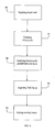
- FIG. 6 is a flowchart of a coating process of the present invention.
- Like reference numbers and designations in the various drawings indicate like elements.
- By the term "functionally graded" it is meant that the materials are co-deposited as known and understood by one of ordinary skill in the art, steadily richening the composition of the coating material until only the coating material is being deposited.
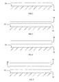
- Referring generally now to FIGS. 2-5, an
article 30 comprises a niobium based refractory metal alloy base or molybdenum based refractory metal alloy base substrate and abond coat layer 32. Thebond coat layer 32 may generally comprise a silica compatible molybdenum disilicide base material. A functionally gradedmaterial layer 34 may be disposed upon thebond coat layer 32. A thermalbarrier coating layer 36 may be disposed upon the functionally gradedmaterial layer 34, if present, or directly upon thebond coat layer 32. - The
article 30 may comprise a niobium based refractory metal alloy base substrate or a molybdenum based refractory metal alloy base substrate. These base substrates form a protective silica scale 33 at high temperatures analogous to the alumina scale for nickel-based superalloys. Molybdenum-based refractory metal alloys, for example, when compared to nickel-based superalloys, exhibit higher melting points (about 4,000°F-5,000°F (~2204°C-2760°C)), higher thermal conductivity (about 690 BTU-in/hr ft2-°F (~100 W/M/K)), low thermal expansion (about 3.5x10⁻⁶/°F (~6.3 x 10⁻⁶/°C)), and high modulus. Suitable molybdenum based refractory metal alloys may comprise about 91 weight percent to 98.5 weight percent of molybdenum, about 1.5 weight percent to 4.5 weight percent of silicon and about 0.5 weight percent to 4.5 weight percent of boron based upon the weight of said alloy. In addition, a silicon base substrate may also be employed. The silicon base substrate may be a silicon ceramic substrate or a silicon containing metal. Suitable silicon base substrate include, but are not limited to, silicon carbide, silicon nitride, and the like, and comprise a silicon containing matrix with reinforcing materials such as fibers, particles and the like, as known to one of ordinary skill in the art. - The
bond coat layer 32 may comprise a silica compatible molybdenum disilicide base material with additions of a silicon nitride base material, e.g., MoSi2 and Si3N4. MoSi2 has a high melting point (about 3398°F (~1870°C)) and forms a silica scale when oxidized which is compatible with a silica-forming alloy such as the molybdenum-based refractory metal alloy base substrate ofarticle 30. However, MoSi2 possesses a high coefficient of thermal expansion (hereinafter referred to as "CTE") (about 5.5x10⁻⁶/°F (~9.9 x 10⁻⁶/°C)) when compared to typical refractory metal alloy substrates, low fracture toughness, and poor high temperature creep strength. The addition of Si3N4 (CTE about 3x10⁻⁶/°F (~5.4 x 10⁻⁶/°C)) can improve the creep strength by a factor of 5, the room temperature fracture toughness by a factor of 2, and lower the CTE of the MoSi2. Additional materials exhibiting low coefficients of thermal expansion may be added to the bond coat composition. Suitable low CTE materials include SiC, Ta2O5, and the like. In the alternative, Si3N4 may be substituted with one or more of the aforementioned low CTE materials. Generally, suitable bond coat layers may comprise about 10 percent by weight to 40 percent by weight of silicon nitride and about 60 percent by weight to 90 percent by weight of molybdenum disilicide based upon the weight of the bond coat layer. - The functionally graded
material layer 34 may generally comprising molybdenum disilicide, mullite and at least one of the following: silicon nitride, silicon carbide or tantalum oxide. The functionally gradedmaterial layer 34 is designed to minimize thermomechanical incompatibility at interfaces between two different materials. As is understood by one of ordinary skill in the art, the functionally gradedmaterial layer 34 steadily increases in mullite composition from the interface with thebond coat layer 32 and eventually becomes pure mullite, that is, 100% by weight of mullite based upon the weight of the functionally graded material layer, at the interface with the thermalbarrier coating layer 36. - The thermal
barrier coating layer 36 may generally comprise an alumina containing ceramic, e.g., mullite, zircon (ZrSiO4), rare earth silicates, combinations of at least one of the foregoing, and the like. Suitable rare earth silicates include, but are not limited to, yttrium silicate, yttrium disilicate, magnesium aluminate spinel, and the like. Alumina containing ceramics provide chemical stability with respect to a silica scale. For example, mullite offers a high melting point, i.e., 3,500°F (~1926°C), a low thermal conductivity (about 24 BTU-in/hr ft2-°F (~3.5 W/M/K)), and a low CTE (about 3x10⁻⁶/°F (~5.4 x 10⁻⁶/°C)). - Referring now to FIG. 6, the
bond coat layer 32 may be applied to at least one surface of thearticle 30 as shown atstep 40 of FIG. 6. Thebond coat layer 32 may be applied using an application process such as, but not limited to, plasma spraying processes (e.g., APS, LPPS, etc.), sol gel processes and slurry processes. Preferably, thebond coat layer 32 is applied to the article's surface(s) using a plasma spray process, e.g., air plasma spray, as known to one of ordinary skill in the art. As a result of applying and subjecting bond coat materials to high processing temperatures, a protective silica scale 33 may form as shown atstep 41 of FIG. 6. - The functionally graded
material layer 34 may be applied as described herein upon thebond coat layer 32 as shown atstep 42 of FIG. 6. Suitable co-deposition processes may be utilized as known to one of ordinary skill in the art. - The thermal
barrier coating layer 36 may be applied upon the functionally gradedmaterial layer 34 as shown atstep 44 of FIG. 6. Suitable application processes may be utilized as known to one of ordinary skill in the art. - The coated surfaces of
article 30, that is, the coating layers 32, 34 and 36, may then be dried using suitable heat treating or drying processes as known to one of ordinary skill in the art. - Referring again to FIG. 4, the
bond coat layer 32 may have a thickness of about 1 mil to 50 mils (~0.025 mm - 1.27 mm), when the thermalbarrier coating layer 36 is not present. Referring again to FIG. 5, thebond coat layer 32 may have a thickness of about 1 mil to 20 mils (~0.025 - 0.51 mm), and preferably about 1 mil to 10 mils (~0.025 - 0.25 mm), when the thermalbarrier coating layer 36 is present. - Various articles may be coated using the bond coat materials and thermal barrier compositions described herein. The excellent mechanical properties at high temperatures of molybdenum and niobium based refractory metal alloys with compatible thermal barrier coating systems, such as moly-disilicide based bond coats and mullite, make them well suited for use with gas turbine engine components. Suitable gas turbine engine components include, but are not limited to, seals, e.g., blade outer air seals; combustor panels, turbine blades and vanes, nozzle components, and liners.
- A series of molybdenum refractory metal alloy substrates (hereinafter referred to as "MRAs") were coated with mullite, silica, MoSi2, a mixture of 70 MoSi2/30 Si3N4, a mixture of 50 MoSi2/50 Si3N4, respectively, to form a bond coat layer on each MRA. The coated MRAs were then subjected to heat at the various temperature ranges (°F) listed in Table 1 and certain mechanical properties of each coating were measured.
Table 1 T Range Mullite Silica MoSi2 70 MoSl2/30 Si3N4 50 MoSi2/50 Si3N4 MRA 2500 2100 Young's Modulus (ksi) 5000 2500 25000 28000 29000 38000 Poisson's Ratio 0.3 0.4 0.17 0.24 0.25 0.38 CTE (ppm/F) 2.8 5 5.5 4.19 3.92 4.25 T Range Mullite Silica MoSi2 70 MoSi2/30 Si3N4 50 MoSi2/50 Si3N4 MRA 2100 1700 Young's Modulus (ksi) 8000 5000 33000 32500 32000 41000 Poisson's Ratio 0.26 0.3 0.168 0.23 0.24 0.35 CTE (ppm/F) 2.69 1 5.3 4.12 3.9 3.9 T Range Mullite Silica MoSi2 70 MoSi2/30 Si3N4 50 MoSi2/50 Si3N4 MRA 1700 1300 Young's Modulus (ksi) 11000 8000 37500 36500 36000 43500 Poisson's Ratio 0.26 0.22 0.166 0.22 0.23 0.33 CTE (ppm/F) 2.58 0.5 5.15 4 3.58 3.6 T Range Mullite Silica MoSi2 70 MoSi2/30 ShN4 50 MoSi2/50 Si3N4 MRA 1300 900 Young's Modulus (ksi) 11000 9000 40000 39000 38500 45500 Poisson's Ratio 0.26 0.2 0.164 0.21 0.22 0.31 CTE (ppm/F) 2.44 0.4 5 3.78 3.25 3.3 T Range Mullite Silica MoSi2 70 MoSi2/30 Si3N4 50 MoSi2/50 Si3N4 MRA 900 500 Young's Modulus (ksi) 11000 9500 42500 41500 40750 47000 Poisson's Ratio 0.25 0.2 0.161 0.205 0.21 0.3 CTE (ppm/F) 2.22 0.3 4.7 3.45 3.08 3.15 T Range Mullite Silica MoSi2 70 MoSi2/30 Si3N4 50 MoSi2/50 Si3N4 MRA 500 77 Young's Modulus (ksi) 11000 10000 45000 43000 42750 48000 Poisson's Ratio 0.24 0.2 0.15 0.198 0.203 0.29 CTE (ppm/F) 1.56 0.25 4.4 3.28 2.95 3 - Referring now to Table 1, the experimental results demonstrate that bond coats comprising either a mixture of 70 MoSi2/30 Si3N4 or a mixture of 50 MoSi2/50 Si3N4 exhibit CTEs closer to the MRA substrate CTE than the CTEs of any one of mullite, silica or moly-disilicide taken alone at various temperature ranges. As described herein, mullite alone may be employed as the thermal barrier coating. Although the mullite CTE and either the 70 MoSi2/30 Si3N4 mixture CTE or the 50 MoSi2/50 Si3N4 mixture CTE are not close, the functionally graded layer described herein serves to minimize thermomechanical incompatibility at the bond coat layer to thermal barrier coating layer interface. Due to the composition of the functionally graded material layer described herein the functionally graded material layer CTE will possess a CTE having a range, e.g., between about 3.0x10⁻⁶/°F to 4.5x10⁻⁶/°F (~5.4 x 10⁻⁶/°C to 8.1 x 10⁻⁶/°C), encompassing both the bond coat layer CTE and the thermal barrier coating layer CTE.
- The bond coat composition, thermal barrier coating composition and processes for applying the same to an article exhibit advantages over the prior art. The use of a functionally graded material layer minimizes stresses experienced between coating interfaces and lessens the likelihood that the bond coat and/or thermal barrier coating do not spall, pest, and the like, prior to achieving the intended useful service life of the coated article, part, etc. By employing a plasma spraying process, the process of the present invention may be operated more efficiently at less cost and in less time, and larger amounts of Si3N4 may be incorporated that are optimal to minimizing stresses without experiencing typical operating obstacles known to one of ordinary skill in the art.
- It is to be understood that the invention is not limited to the illustrations described and shown herein, which are deemed to be merely illustrative of the best modes of carrying out the invention, and which are susceptible to modification of form, size, arrangement of parts, and details of operation. The invention rather is intended to encompass all such modifications which are within its scope as defined by the claims.
Claims (20)
- A process for coating an article (30), comprising:applying upon at least one surface of a molybdenum based refractory metal alloy base or niobium based refractory metal alloy base or silicon base substrate a bond coat material layer (32) comprising a molybdenum disilicide base compound and at least one of the following: silicon nitride, silicon carbide or tantalum oxide.
- The process of claim 1, wherein the application step comprises an application process selected from the group consisting of plasma spraying processes, sol gel processes and slurry processes.
- The process of claim 1 or 2, further comprising forming a layer (33) of thermally grown oxide upon said bond coat material layer (32).
- The process of claim 3, further comprising applying a thermal barrier composition layer (36) upon said thermally grown oxide layer.
- The process of claim 1, further comprising applying a thermal barrier composition layer (36) upon said bond coat material layer (32).
- The process of any preceding claim, further comprising drying said substrate.
- The process of claim 1, further comprising applying upon said bond coat material layer (32) a functionally graded material layer (34) comprising molybdenum disilicide, mullite and at least one of the following: silicon nitride, silicon carbide or tantalum oxide.
- A coated article (30), comprising:an article (30) having at least one surface and comprised of a molybdenum based refractory metal alloy or a niobium based refractory metal alloy or a silicon base; anda bond coat layer (32) disposed upon said at least one surface, said bond coat layer (32) comprises a molybdenum disilicide base compound and at least one of the following: silicon nitride, silicon carbide or tantalum oxide.
- The article of claim 8, further comprising a thermally grown oxide layer (33) disposed upon said bond coat layer (32).
- The article of claim 8, further comprising a functionally graded material layer (34) disposed upon said bond coat layer (32), said functionally graded material layer (34) comprising molybdenum disilicide, mullite and at least one of the following: silicon nitride, silicon carbide or tantalum oxide.
- The article of claim 10, wherein said functionally graded material layer (34) comprises a coefficient of thermal expansion between about 3.0x10⁻⁶/°F and 4.5x10⁻⁶/°F (~5.4 x 10⁻⁶/°C and 8.1. x 10-6/°C).
- The article of claim 10 or 11, further comprising a thermal barrier coating layer (36) disposed upon said functionally graded material layer (34).
- The article of claim 12, wherein said bond coat layer comprises a thickness of about 1 mil to 20 mils (~0.025 - 0.51 mm).
- The article of claim 8, further comprising a thermal barrier coating layer (36) disposed upon said bond coat layer (32), said thermal barrier coating (36) comprises a material selected from the group consisting of mullite, zirconium silicate, yttrium silicate, yttrium disilicate, and magnesium aluminate spinel.
- The coated article of any of claims 10 to 14, wherein said molybdenum base refractory metal alloy comprises about 91 weight percent to 98.5 weight percent of molybdenum, about 1.5 weight percent to 4.5 weight percent of silicon and about 0.5 weight percent to 4.5 weight percent of boron base upon the weight of said alloy.
- The coated article of any of claims 8 to 15, wherein said bond coat layer (32) comprises about 10 percent by weight to 40 percent by volume of silicon nitride base compound and about 60 percent by weight to 90 percent by weight of molybdenum disilicide base compound base upon the weight of said bond coat layer.
- The coated article of any of claims 8 to 16, wherein said article (30) is a gas turbine engine component selected from the group consisting of seals, combustor panels, blades, vanes, liners, nozzles and nozzle components.
- The coated article of any of claims 8 to 17, wherein said bond coat layer (32) comprises a thickness of about 1 mil to 50 mils (~0.025 - 1.27 mm).
- A process for coating an article (30), comprising:applying upon at least one surface of a molybdenum based refractory metal alloy base substrate, a niobium based refractory metal alloy base substrate or a silicon base substrate a bond coat material layer (32) comprising a molybdenum disilicide base compound and at least one of the following: silicon nitride, silicon carbide or tantalum oxide;applying upon said bond coat material layer (32) a functionally graded material layer (34) comprising molybdenum disilicide, mullite and at least one of the following: silicon nitride, silicon carbide or tantalum oxide; andapplying upon said functionally graded material layer (34) a thermal barrier coating layer (36).
- A coated article, comprising:an article (30) having at least one surface and comprised of a molybdenum based refractory metal alloy, a niobium based refractory metal alloy or a silicon base;a bond coat layer (32) disposed upon said at least one surface, said bond coat layer (32) includes a molybdenum disilicide base compound and at least one of the following: silicon nitride, silicon carbide or tantalum oxide;a functionally graded material layer (34) disposed upon said bond coat layer (32), said functionally graded material layer (34) comprising molybdenum disilicide, mullite and at least one of the following: silicon nitride, silicon carbide or tantalum oxide, said functionally graded material layer having a coefficient of thermal expansion between about 3.0x10⁻⁶/°F and 4.5x10⁻⁶/°F (~5.4 X 10⁻⁶/°C and 8.1 x 10⁻⁶/°C) ; anda thermal barrier coating layer (36) disposed upon said functionally graded layer (34).
Applications Claiming Priority (1)
| Application Number | Priority Date | Filing Date | Title |
|---|---|---|---|
| US11/375,553 US7763356B2 (en) | 2006-03-13 | 2006-03-13 | Bond coating and thermal barrier compositions, processes for applying both, and their coated articles |
Publications (3)
| Publication Number | Publication Date |
|---|---|
| EP1842937A2 true EP1842937A2 (en) | 2007-10-10 |
| EP1842937A3 EP1842937A3 (en) | 2008-08-27 |
| EP1842937B1 EP1842937B1 (en) | 2014-09-03 |
Family
ID=37988965
Family Applications (1)
| Application Number | Title | Priority Date | Filing Date |
|---|---|---|---|
| EP20070250080 Active EP1842937B1 (en) | 2006-03-13 | 2007-01-09 | Bond coating and thermal barrier compositions, processes for applying both, and their coated articles |
Country Status (4)
| Country | Link |
|---|---|
| US (2) | US7763356B2 (en) |
| EP (1) | EP1842937B1 (en) |
| JP (1) | JP2007247055A (en) |
| KR (1) | KR20070093318A (en) |
Cited By (5)
| Publication number | Priority date | Publication date | Assignee | Title |
|---|---|---|---|---|
| EP2113583A1 (en) * | 2008-04-28 | 2009-11-04 | The Boeing Company | Built-up composite structures with a graded coefficient of thermal expansion for extreme environment applications |
| CN101885622A (en) * | 2010-06-11 | 2010-11-17 | 陕西科技大学 | A kind of preparation method of C/C composite material SiC coated mullite composite coating |
| RU2437960C2 (en) * | 2009-12-09 | 2011-12-27 | Государственное образовательное учреждение высшего профессионального образования "Алтайский государственный университет" | Procedure for heat resistant coating of tungsten or tantalum |
| WO2014150465A3 (en) * | 2013-03-15 | 2015-02-19 | General Electric Company | Composite coatings and methods therefor |
| EP2980263A1 (en) * | 2014-07-30 | 2016-02-03 | MTU Aero Engines GmbH | Component made from a molybdenum alloy and manufacturing method for the same |
Families Citing this family (26)
| Publication number | Priority date | Publication date | Assignee | Title |
|---|---|---|---|---|
| CN101326303B (en) * | 2005-10-18 | 2012-07-18 | 西南研究院 | Erosion resistant coatings |
| US20090214787A1 (en) * | 2005-10-18 | 2009-08-27 | Southwest Research Institute | Erosion Resistant Coatings |
| US8461477B2 (en) | 2009-08-19 | 2013-06-11 | General Electric Company | Method for determining laser shock peening approach accessibility |
| US8790791B2 (en) | 2010-04-15 | 2014-07-29 | Southwest Research Institute | Oxidation resistant nanocrystalline MCrAl(Y) coatings and methods of forming such coatings |
| US8876458B2 (en) | 2011-01-25 | 2014-11-04 | United Technologies Corporation | Blade outer air seal assembly and support |
| SE535684C2 (en) * | 2011-03-22 | 2012-11-06 | Diamorph Ab | Method of producing a gradient component of metal / cemented carbide |
| US9511572B2 (en) | 2011-05-25 | 2016-12-06 | Southwest Research Institute | Nanocrystalline interlayer coating for increasing service life of thermal barrier coating on high temperature components |
| US8956700B2 (en) | 2011-10-19 | 2015-02-17 | General Electric Company | Method for adhering a coating to a substrate structure |
| US10774682B2 (en) * | 2012-06-22 | 2020-09-15 | The United States of America as Represented by the Administrator of National Aeromautics and Space Administration | Advanced high temperature and fatigue resistant environmental barrier coating bond coat systems for SiC/SiC ceramic matrix composites |
| US9428650B2 (en) | 2012-12-11 | 2016-08-30 | General Electric Company | Environmental barrier coatings and methods therefor |
| WO2014204480A1 (en) * | 2013-06-21 | 2014-12-24 | United States Of America, As Represented By The Administrator Of The National Aeronautics And Space Administration | Environmental barrier coating bond coat systems |
| US9561986B2 (en) | 2013-10-31 | 2017-02-07 | General Electric Company | Silica-forming articles having engineered surfaces to enhance resistance to creep sliding under high-temperature loading |
| US10329934B2 (en) * | 2014-12-15 | 2019-06-25 | United Technologies Corporation | Reversible flow blade outer air seal |
| US9523146B1 (en) | 2015-06-17 | 2016-12-20 | Southwest Research Institute | Ti—Si—C—N piston ring coatings |
| US20170167276A1 (en) * | 2015-12-09 | 2017-06-15 | General Electric Company | Article for high temperature service |
| US10604454B1 (en) | 2016-06-16 | 2020-03-31 | United States Of America As Represented By The Administrator Of National Aeronautics And Space Administration | Advanced high temperature environmental barrier coating for SiC/SiC ceramic matrix composites |
| US11958786B1 (en) | 2016-12-05 | 2024-04-16 | United States Government Administrator Of Nasa | Calcium-magnesium aluminosilicate (CMAS) resistant thermal and environmental barrier coatings |
| US11066339B2 (en) | 2017-06-08 | 2021-07-20 | General Electric Company | Article for high temperature service |
| US11773734B2 (en) | 2017-09-07 | 2023-10-03 | General Electric Company | Liquid bond coatings for barrier coatings |
| US11639315B2 (en) | 2017-09-07 | 2023-05-02 | General Electric Company | Bond coatings having a molten silicon-phase contained between refractory layers |
| US11401217B2 (en) | 2017-09-07 | 2022-08-02 | General Electric Company | Bond coatings having a silicon-phase contained within a refractory phase |
| CA3116145A1 (en) * | 2018-10-15 | 2020-04-23 | Asml Netherlands B.V. | Method of manufacturing a membrane assembly |
| US11760696B2 (en) * | 2019-01-04 | 2023-09-19 | Rtx Corporation | Ceramic matrix composite component with modified thermal expansion and method for producing the same |
| EP3954806A1 (en) | 2020-08-14 | 2022-02-16 | Raytheon Technologies Corporation | Environmental barrier coating |
| CN113248261B (en) * | 2021-06-16 | 2022-05-10 | 北京理工大学 | A kind of molybdenum disilicide-coated tantalum boride-hafnium carbide spherical powder and preparation method thereof |
| CN115849710B (en) * | 2022-12-09 | 2024-06-25 | 湖南旗滨医药材料科技有限公司 | Gradient air hole glass rotary tube and preparation method thereof |
Citations (2)
| Publication number | Priority date | Publication date | Assignee | Title |
|---|---|---|---|---|
| US20050042461A1 (en) | 2003-08-18 | 2005-02-24 | Honeywell International Inc. | Diffusion barrier coating for si-based components |
| US20050079343A1 (en) | 2003-10-08 | 2005-04-14 | Honeywell International Inc. | Braze-based protective coating for silicon nitride |
Family Cites Families (22)
| Publication number | Priority date | Publication date | Assignee | Title |
|---|---|---|---|---|
| US5472487A (en) * | 1991-01-18 | 1995-12-05 | United Technologies Corporation | Molybdenum disilicide based materials with reduced coefficients of thermal expansion |
| US5308806A (en) * | 1992-01-13 | 1994-05-03 | United Technologies Corporation | Method for improving refractory metal fiber reinforced molybdenum disilicide composites |
| WO1993024672A1 (en) * | 1992-05-29 | 1993-12-09 | United Technologies Corporation | Ceramic thermal barrier coating for rapid thermal cycling applications |
| US5693156A (en) * | 1993-12-21 | 1997-12-02 | United Technologies Corporation | Oxidation resistant molybdenum alloy |
| EP0722920B9 (en) * | 1994-08-09 | 2002-06-12 | Kabushiki Kaisha Toyota Chuo Kenkyusho | Composite material and production method therefor |
| US6200691B1 (en) * | 1998-04-20 | 2001-03-13 | Colorado School Of Mines | Oxidation resistance coating system for refractory metals |
| US6296941B1 (en) * | 1999-04-15 | 2001-10-02 | General Electric Company | Silicon based substrate with yttrium silicate environmental/thermal barrier layer |
| US6288000B1 (en) * | 2000-02-09 | 2001-09-11 | Ohio Aerospace Institute | Pest resistant MoSi2-based materials containing in-situ grown β-Si3N4whiskers |
| US6503575B1 (en) * | 2000-05-22 | 2003-01-07 | Praxair S.T. Technology, Inc. | Process for producing graded coated articles |
| US6497968B2 (en) * | 2001-02-26 | 2002-12-24 | General Electric Company | Oxidation resistant coatings for molybdenum silicide-based composite articles |
| KR100454715B1 (en) * | 2002-03-14 | 2004-11-05 | 한국과학기술연구원 | MoSi2-Si3N4 COMPOSITE COATING AND MANUFACTURING METHOD THEREOF |
| US6759151B1 (en) * | 2002-05-22 | 2004-07-06 | The United States Of America As Represented By The Administrator Of The National Aeronautics And Space Administration | Multilayer article characterized by low coefficient of thermal expansion outer layer |
| US6733908B1 (en) * | 2002-07-08 | 2004-05-11 | The United States Of America As Represented By The Administrator Of The National Aeronautics And Space Administration | Multilayer article having stabilized zirconia outer layer and chemical barrier layer |
| US6652674B1 (en) * | 2002-07-19 | 2003-11-25 | United Technologies Corporation | Oxidation resistant molybdenum |
| US7005191B2 (en) * | 2003-05-01 | 2006-02-28 | Wisconsin Alumni Research Foundation | Oxidation resistant coatings for ultra high temperature transition metals and transition metal alloys |
| US7056574B2 (en) * | 2003-05-22 | 2006-06-06 | United Technologies Corporation | Bond layer for silicon containing substrate |
| US7060360B2 (en) * | 2003-05-22 | 2006-06-13 | United Technologies Corporation | Bond coat for silicon based substrates |
| US7063894B2 (en) * | 2003-05-22 | 2006-06-20 | United Technologies Corporation | Environmental barrier coating for silicon based substrates |
| US7329101B2 (en) * | 2004-12-29 | 2008-02-12 | General Electric Company | Ceramic composite with integrated compliance/wear layer |
| US7354651B2 (en) * | 2005-06-13 | 2008-04-08 | General Electric Company | Bond coat for corrosion resistant EBC for silicon-containing substrate and processes for preparing same |
| US7407718B2 (en) * | 2005-06-13 | 2008-08-05 | General Electric Company | Thermal/environmental barrier coating system for silicon-containing materials |
| US7722959B2 (en) * | 2006-09-06 | 2010-05-25 | United Technologies Corporation | Silicate resistant thermal barrier coating with alternating layers |
-
2006
- 2006-03-13 US US11/375,553 patent/US7763356B2/en active Active
- 2006-12-20 KR KR1020060130870A patent/KR20070093318A/en not_active Ceased
- 2006-12-28 JP JP2006353623A patent/JP2007247055A/en active Pending
-
2007
- 2007-01-09 EP EP20070250080 patent/EP1842937B1/en active Active
-
2010
- 2010-03-31 US US12/751,091 patent/US20100189911A1/en not_active Abandoned
Patent Citations (2)
| Publication number | Priority date | Publication date | Assignee | Title |
|---|---|---|---|---|
| US20050042461A1 (en) | 2003-08-18 | 2005-02-24 | Honeywell International Inc. | Diffusion barrier coating for si-based components |
| US20050079343A1 (en) | 2003-10-08 | 2005-04-14 | Honeywell International Inc. | Braze-based protective coating for silicon nitride |
Cited By (8)
| Publication number | Priority date | Publication date | Assignee | Title |
|---|---|---|---|---|
| EP2113583A1 (en) * | 2008-04-28 | 2009-11-04 | The Boeing Company | Built-up composite structures with a graded coefficient of thermal expansion for extreme environment applications |
| US8512808B2 (en) | 2008-04-28 | 2013-08-20 | The Boeing Company | Built-up composite structures with a graded coefficient of thermal expansion for extreme environment applications |
| US10316792B2 (en) | 2008-04-28 | 2019-06-11 | The Boeing Company | Built-up composite structures with a graded coefficient of thermal expansion for extreme environment applications |
| RU2437960C2 (en) * | 2009-12-09 | 2011-12-27 | Государственное образовательное учреждение высшего профессионального образования "Алтайский государственный университет" | Procedure for heat resistant coating of tungsten or tantalum |
| CN101885622A (en) * | 2010-06-11 | 2010-11-17 | 陕西科技大学 | A kind of preparation method of C/C composite material SiC coated mullite composite coating |
| WO2014150465A3 (en) * | 2013-03-15 | 2015-02-19 | General Electric Company | Composite coatings and methods therefor |
| US10093810B2 (en) | 2013-03-15 | 2018-10-09 | General Electric Company | Composite coatings and methods therefor |
| EP2980263A1 (en) * | 2014-07-30 | 2016-02-03 | MTU Aero Engines GmbH | Component made from a molybdenum alloy and manufacturing method for the same |
Also Published As
| Publication number | Publication date |
|---|---|
| US20100189911A1 (en) | 2010-07-29 |
| EP1842937B1 (en) | 2014-09-03 |
| EP1842937A3 (en) | 2008-08-27 |
| JP2007247055A (en) | 2007-09-27 |
| US7763356B2 (en) | 2010-07-27 |
| KR20070093318A (en) | 2007-09-18 |
| US20100104859A1 (en) | 2010-04-29 |
Similar Documents
| Publication | Publication Date | Title |
|---|---|---|
| EP1842937B1 (en) | Bond coating and thermal barrier compositions, processes for applying both, and their coated articles | |
| US6759151B1 (en) | Multilayer article characterized by low coefficient of thermal expansion outer layer | |
| US7063894B2 (en) | Environmental barrier coating for silicon based substrates | |
| EP1479659B1 (en) | Bond coating for silicon based substrates such as silicon nitride | |
| US7357994B2 (en) | Thermal/environmental barrier coating system for silicon-containing materials | |
| US7060360B2 (en) | Bond coat for silicon based substrates | |
| US6733908B1 (en) | Multilayer article having stabilized zirconia outer layer and chemical barrier layer | |
| EP2245096B1 (en) | Cmas-resistant articles | |
| JP5068902B2 (en) | Ceramic with zircon coating | |
| EP1479661B1 (en) | Coating for silicon containing substrate | |
| EP1416066B1 (en) | Thermal/environmental barrier coating for silicon-containing substrate | |
| US9365725B2 (en) | Articles for high temperature service and methods for their manufacture | |
| EP1683775B1 (en) | Thermal/environmental barrier coating with transition layer for silicon comprising materials | |
| EP1764351A2 (en) | Silicon based substrate with hafnium silicate containing barrier layer | |
| KR20070090065A (en) | Adhesive protective coating, method of providing invisible line of adhesive protective coating and coated article | |
| EP1044944B1 (en) | Silicon based substrate with yttrium silicate environmental/thermal barrier layer and method for preparing an article therefrom | |
| EP1683772B1 (en) | Thermal/environmental barrier coating with transition layer for silicon-comprising materials | |
| US7407718B2 (en) | Thermal/environmental barrier coating system for silicon-containing materials | |
| US20050129973A1 (en) | Velocity barrier layer for environmental barrier coatings | |
| EP1479660B1 (en) | Coating for silicon containing substrate | |
| EP4508144A1 (en) | Environmental barrier materials and coatings containing low melting temperature phases | |
| CA3192879A1 (en) | Si-based composite bond coat containing cristobalite modifier for environmental barrier coatings |
Legal Events
| Date | Code | Title | Description |
|---|---|---|---|
| PUAI | Public reference made under article 153(3) epc to a published international application that has entered the european phase |
Free format text: ORIGINAL CODE: 0009012 |
|
| AK | Designated contracting states |
Kind code of ref document: A2 Designated state(s): AT BE BG CH CY CZ DE DK EE ES FI FR GB GR HU IE IS IT LI LT LU LV MC NL PL PT RO SE SI SK TR |
|
| AX | Request for extension of the european patent |
Extension state: AL BA HR MK YU |
|
| PUAL | Search report despatched |
Free format text: ORIGINAL CODE: 0009013 |
|
| AK | Designated contracting states |
Kind code of ref document: A3 Designated state(s): AT BE BG CH CY CZ DE DK EE ES FI FR GB GR HU IE IS IT LI LT LU LV MC NL PL PT RO SE SI SK TR |
|
| AX | Request for extension of the european patent |
Extension state: AL BA HR MK RS |
|
| RIC1 | Information provided on ipc code assigned before grant |
Ipc: C23C 4/06 20060101ALI20080718BHEP Ipc: C22C 27/04 20060101ALI20080718BHEP Ipc: C23C 26/00 20060101ALI20080718BHEP Ipc: C23C 28/00 20060101ALI20080718BHEP Ipc: C23C 28/04 20060101ALI20080718BHEP Ipc: C23C 4/04 20060101AFI20070509BHEP |
|
| 17P | Request for examination filed |
Effective date: 20090114 |
|
| 17Q | First examination report despatched |
Effective date: 20090310 |
|
| AKX | Designation fees paid |
Designated state(s): DE GB |
|
| REG | Reference to a national code |
Ref country code: DE Ref legal event code: R079 Ref document number: 602007038385 Country of ref document: DE Free format text: PREVIOUS MAIN CLASS: C23C0004040000 Ipc: C04B0035580000 |
|
| RIC1 | Information provided on ipc code assigned before grant |
Ipc: C04B 35/58 20060101AFI20131211BHEP Ipc: C22C 27/04 20060101ALI20131211BHEP Ipc: C23C 26/00 20060101ALI20131211BHEP Ipc: C23C 28/00 20060101ALI20131211BHEP Ipc: C23C 28/04 20060101ALI20131211BHEP Ipc: C23C 4/06 20060101ALI20131211BHEP Ipc: C23C 4/04 20060101ALI20131211BHEP |
|
| GRAP | Despatch of communication of intention to grant a patent |
Free format text: ORIGINAL CODE: EPIDOSNIGR1 |
|
| INTG | Intention to grant announced |
Effective date: 20140128 |
|
| GRAS | Grant fee paid |
Free format text: ORIGINAL CODE: EPIDOSNIGR3 |
|
| GRAP | Despatch of communication of intention to grant a patent |
Free format text: ORIGINAL CODE: EPIDOSNIGR1 |
|
| GRAS | Grant fee paid |
Free format text: ORIGINAL CODE: EPIDOSNIGR3 |
|
| INTG | Intention to grant announced |
Effective date: 20140701 |
|
| GRAA | (expected) grant |
Free format text: ORIGINAL CODE: 0009210 |
|
| AK | Designated contracting states |
Kind code of ref document: B1 Designated state(s): DE GB |
|
| REG | Reference to a national code |
Ref country code: GB Ref legal event code: FG4D |
|
| REG | Reference to a national code |
Ref country code: DE Ref legal event code: R081 Ref document number: 602007038385 Country of ref document: DE Owner name: UNITED TECHNOLOGIES CORP. (N.D.GES.D. STAATES , US Free format text: FORMER OWNER: UNITED TECHNOLOGIES CORP., HARTFORD, CONN., US |
|
| REG | Reference to a national code |
Ref country code: DE Ref legal event code: R096 Ref document number: 602007038385 Country of ref document: DE Effective date: 20141016 |
|
| REG | Reference to a national code |
Ref country code: DE Ref legal event code: R097 Ref document number: 602007038385 Country of ref document: DE |
|
| PLBE | No opposition filed within time limit |
Free format text: ORIGINAL CODE: 0009261 |
|
| STAA | Information on the status of an ep patent application or granted ep patent |
Free format text: STATUS: NO OPPOSITION FILED WITHIN TIME LIMIT |
|
| 26N | No opposition filed |
Effective date: 20150604 |
|
| REG | Reference to a national code |
Ref country code: DE Ref legal event code: R082 Ref document number: 602007038385 Country of ref document: DE Representative=s name: SCHMITT-NILSON SCHRAUD WAIBEL WOHLFROM PATENTA, DE |
|
| REG | Reference to a national code |
Ref country code: DE Ref legal event code: R082 Ref document number: 602007038385 Country of ref document: DE Representative=s name: SCHMITT-NILSON SCHRAUD WAIBEL WOHLFROM PATENTA, DE Ref country code: DE Ref legal event code: R081 Ref document number: 602007038385 Country of ref document: DE Owner name: UNITED TECHNOLOGIES CORP. (N.D.GES.D. STAATES , US Free format text: FORMER OWNER: UNITED TECHNOLOGIES CORP., HARTFORD, CONN., US |
|
| REG | Reference to a national code |
Ref country code: DE Ref legal event code: R081 Ref document number: 602007038385 Country of ref document: DE Owner name: RAYTHEON TECHNOLOGIES CORPORATION (N.D.GES.D.S, US Free format text: FORMER OWNER: UNITED TECHNOLOGIES CORP. (N.D.GES.D. STAATES DELAWARE), FARMINGTON, CONN., US Ref country code: DE Ref legal event code: R081 Ref document number: 602007038385 Country of ref document: DE Owner name: RTX CORPORATION (N.D.GES.D. STAATES DELAWARE),, US Free format text: FORMER OWNER: UNITED TECHNOLOGIES CORP. (N.D.GES.D. STAATES DELAWARE), FARMINGTON, CONN., US |
|
| P01 | Opt-out of the competence of the unified patent court (upc) registered |
Effective date: 20230519 |
|
| REG | Reference to a national code |
Ref country code: DE Ref legal event code: R081 Ref document number: 602007038385 Country of ref document: DE Owner name: RTX CORPORATION (N.D.GES.D. STAATES DELAWARE),, US Free format text: FORMER OWNER: RAYTHEON TECHNOLOGIES CORPORATION (N.D.GES.D.STAATES DELAWARE), ARLINGTON, VA, US |
|
| PGFP | Annual fee paid to national office [announced via postgrant information from national office to epo] |
Ref country code: GB Payment date: 20251217 Year of fee payment: 20 |
|
| PGFP | Annual fee paid to national office [announced via postgrant information from national office to epo] |
Ref country code: DE Payment date: 20251217 Year of fee payment: 20 |