EP1842763A1 - Hydraulically driven vehicle - Google Patents
Hydraulically driven vehicle Download PDFInfo
- Publication number
- EP1842763A1 EP1842763A1 EP07007084A EP07007084A EP1842763A1 EP 1842763 A1 EP1842763 A1 EP 1842763A1 EP 07007084 A EP07007084 A EP 07007084A EP 07007084 A EP07007084 A EP 07007084A EP 1842763 A1 EP1842763 A1 EP 1842763A1
- Authority
- EP
- European Patent Office
- Prior art keywords
- swinging member
- pin
- swinging
- vehicle
- speed
- Prior art date
- Legal status (The legal status is an assumption and is not a legal conclusion. Google has not performed a legal analysis and makes no representation as to the accuracy of the status listed.)
- Granted
Links
- 230000005540 biological transmission Effects 0.000 claims abstract description 44
- 230000002706 hydrostatic effect Effects 0.000 claims description 33
Images








Classifications
-
- B—PERFORMING OPERATIONS; TRANSPORTING
- B60—VEHICLES IN GENERAL
- B60K—ARRANGEMENT OR MOUNTING OF PROPULSION UNITS OR OF TRANSMISSIONS IN VEHICLES; ARRANGEMENT OR MOUNTING OF PLURAL DIVERSE PRIME-MOVERS IN VEHICLES; AUXILIARY DRIVES FOR VEHICLES; INSTRUMENTATION OR DASHBOARDS FOR VEHICLES; ARRANGEMENTS IN CONNECTION WITH COOLING, AIR INTAKE, GAS EXHAUST OR FUEL SUPPLY OF PROPULSION UNITS IN VEHICLES
- B60K20/00—Arrangement or mounting of change-speed gearing control devices in vehicles
- B60K20/02—Arrangement or mounting of change-speed gearing control devices in vehicles of initiating means
-
- B—PERFORMING OPERATIONS; TRANSPORTING
- B62—LAND VEHICLES FOR TRAVELLING OTHERWISE THAN ON RAILS
- B62D—MOTOR VEHICLES; TRAILERS
- B62D11/00—Steering non-deflectable wheels; Steering endless tracks or the like
- B62D11/001—Steering non-deflectable wheels; Steering endless tracks or the like control systems
- B62D11/006—Mechanical control systems
Definitions
- the present invention relates to a hydraulically driven vehicle wherein left and right hydrostatic transmissions are driven by an engine, and left and right drive wheels are driven by these left and right hydrostatic transmissions.
- a hydrostatic transmission is equipped with a variable capacity swash-plate hydraulic pump and a hydraulic motor.
- a swash-plate hydraulic pump When a swash-plate hydraulic pump is driven by an engine, the pump produces high-pressure operating oil. When this high-pressure operating oil is supplied to the hydraulic motor, the hydraulic motor rotates. The drive wheels can be turned by the hydraulic motor.
- the engine operates continuously at a constant speed.
- the rotational speed of the input shaft of the swash-plate hydraulic pump is constant, but the amount of operating oil ejected can be changed by varying the angle of inclination of the swash-plate from the exterior.
- the hydraulic motor can be rotated normally, stopped, and reversed by varying the angle of inclination of the swash plate.
- the rotational speed of the output shaft of the hydraulic motor can be varied by adjusting the angle of inclination of the swash plate while the motor is rotated normally or reversed.
- Using a hydrostatic transmission makes it possible to maintain a preferred rotational speed in the engine, to control the speed of the vehicle, to move the vehicle forward, to stop the vehicle, or to move the vehicle in reverse.
- an engine is designed to drive left and right hydrostatic transmissions, wherein a left drive wheel is driven by the left hydrostatic transmission and a right drive wheel is driven by the right hydrostatic transmission, a difference in speed can be created between the left and right drive wheels simply by creating a difference in the swash-plate angles of inclination between the left and right hydrostatic transmissions.
- the vehicle can be arbitrarily turned to the left or to the right without steering the vehicle.
- JP 7-309149 A discloses a hydraulically driven vehicle wherein left and right hydrostatic transmissions are driven by one engine. This hydraulically driven vehicle is described with reference to FIGS. 11 through 13 hereof.
- an engine 102 is mounted in a vehicle frame 101, a left hydrostatic transmission 103L is connected to the engine 102, a left drive wheel 104L is driven by the left hydrostatic transmission 103L, a right hydrostatic transmission 103R is also connected to the engine 102, and a right drive wheel 104R is driven by the right hydrostatic transmission 103R.
- a shift lever 105 disposed in proximity to the right drive wheel 104R When a shift lever 105 disposed in proximity to the right drive wheel 104R is operated, a left push-pull rod 106L and a right push-pull rod 106R move together to the left or right of the drawing. Shift arms 107L, 107R protruding from the hydrostatic transmissions 103L, 103R are thereupon swung simultaneously, and the rotational speeds and rotational directions of the left and right drive wheels 104L, 104R are controlled. Specifically, merely operating the shift lever 105 allows the vehicle to be varied between moving forwards and backwards, and the vehicle speed to be varied among stopping, low speeds, and high speeds.
- a rotating shaft 115 extending towards the front and back of the drawing spans across a base member 114 that is lowered from the vehicle frame 101, as shown in FIG. 12.
- the rotating shaft 115 is mechanically connected to the shift lever 105 via a sub-lever 116, a rod 117, and a sub-lever 118 extending from the shift lever 105. Therefore, the rotating shaft 115 is rotated by the movement of the shift lever 105.
- a pipe 119 extends upward from the rotating shaft 115, and a mixing lever 122 is provided at the top of the pipe 119 via a pin 121.
- a gate-shaped guide member 125 is attached to a pair of pivoting shafts 124, 124 extending from the base member 114, with the guide member capable of swinging to the front and back of the drawing.
- a large groove 126 is formed in the top surface of the guide member 125, and the top of the mixing lever 122 is inserted into this groove 126.
- the groove 126 is shaped along an arc centered on the rotating shaft 115, and the mixing lever 122 does not come out of the groove even when the mixing lever 122 swings along with the rotation of the rotating shaft 115.
- the guide member 125 swings around the pivoting shafts 124 and comes into proximity of either the left push-pull rod 106L or the right push-pull rod 106R, as shown in FIG. 13. A detailed description is not given here, but when the guide member 125 comes into proximity of the left push-pull rod 106L or the right push-pull rod 106R, a difference is created between the amount of movement in the left push-pull rod 106L and the amount of movement in the right push-pull rod 106R.
- the transmission 113 described above has a complicated and bulky structure due to being composed of the pivoting shafts 124, 124, the guide member 125, the rotating shaft 115, the mixing lever 122, and other components. Mounting a complicated and large transmission 113 in a small vehicle makes the vehicle more expensive and larger.
- a hydraulically driven vehicle comprising: an engine mounted on a vehicle frame; a left hydrostatic transmission that is driven by the engine and that drives a left drive wheel; a right hydrostatic transmission that is driven by the engine and that drives a right drive wheel; and a gear-shifting mechanism for transmitting to the hydrostatic transmissions the movement of a speed setting device that is operated by an operator to adjust the traveling speed of the vehicle frame, and the movement of left and right steering devices that are operated by the operator to turn the vehicle frame, the gear-shifting mechanism comprising: a first swinging member that is swingably attached to the vehicle frame with left and right first pins and that is moved by the speed setting device; a left second swinging member that is swingably attached to the first swinging member at a position away from the left and right first pins and that is moved by the left steering device connected at one end; a left resilient member that urges the left second swinging member into the first swinging member so that the left second swinging member swings together with the first swinging member when
- the gear-shifting mechanism is composed of a first swinging member, left and right second swinging members, left and right drive plates, and left and right link plates, and the configuration thereof is simple. As a result, it is easy to reduce the size and cost of the gear-shifting mechanism.
- the second left swinging member is connected by a second left pin to one end of the first swinging member
- the second right swinging member is connected by a second right pin to one end of the first swinging member
- the position of the second left pin is set in the second left swing member while the position of the second right pin is set in the second right swinging member so that the axial center of the second left pin or the axial center of the second right pin is superposed over the axial center of the first pin when the swinging members are operated by the steering devices.
- the directions left and right are determined based on the manner in which the operator holds operating handles 24.
- the directions front and back are determined similarly.
- a hydraulically driven vehicle 10 is composed of a vehicle frame 11; a loading platform 12 and an engine 13 as a drive source, both mounted on the vehicle frame 11; a left hydrostatic transmission 14L and a right hydrostatic transmission 14R (14L is behind 14R; the relationship between L and R is the same hereinbelow as in this drawing) that are disposed below the engine 13 and are driven by the drive force of the engine 13; a left drive wheel 17L and a right drive wheel 17R attached to the output-side shafts of the hydrostatic transmissions 14L, 14R; turning wheels 18 that are attached to the vehicle frame 11; driven wheels 19L, 19R provided at the front of the vehicle frame 11; crawlers 21L, 21R that are wound around the drive wheels, the turning wheels, and the driven wheels; operating handles 24L, 24R that extend upward at a rearward incline from the vehicle frame 11; a speed setting device 26 and left and right steering devices 28L, 28R provided to these operating handles 24L, 24R; and a gear-shifting
- the speed setting device 26 is an operating member for controlling the forward movement, stopping, and reverse movement of the vehicle in addition to speed, and is preferably embodied as a lever, for example.
- the left and right hydrostatic transmissions 14L, 14R are disposed at the rear of the vehicle frame 11; and the gear-shifting mechanism 31 is disposed at the front of the vehicle frame 11, as shown in FIG. 2.
- the steering devices 28L, 28R are provided respectively to the left and right operating handles 24L, 24R extending backward from the vehicle frame 11, and the speed setting device 26 is provided on the right operating handle 24R.
- the left steering device 28L and the gear-shifting mechanism 31 are connected by the a left steering cable 32L; the right steering device 28R and the gear-shifting mechanism 31 are connected by a right steering cable 32R; and the speed setting device 26 and gear-shifting mechanism 31 are connected by a vehicle speed cable 33.
- Push-pull rods 34L, 34R are connected between the gear-shifting mechanism 31 and the left and right hydrostatic transmissions 14L, 14R. These push-pull rods 34L, 34R fulfill the role of transmitting the movement of the gear-shifting mechanism 31 to the left and right hydrostatic transmissions 14L, 14R.
- a first swinging member 43 is attached with first pins 42, 42 to a base bracket 41 attached to the vehicle frame 11 (FIG. 2), as shown in FIG. 3.
- the vehicle speed cable 33 is connected to an end 43a of the first swinging member 43, and the vehicle speed cable 33 is operated by the speed setting device 26 (FIG. 2), allowing the first swinging member to swing around the first pins 42, 42.
- a seesaw-shaped second left swinging member 46L and second right swinging member 46R are attached to the first swinging member 43 at positions separated from the first pins 42, 42. Specifically, a center pin 63L of the second left swinging member 46L is inserted into a hole 62L formed in the distal end of the first swinging member 43, and a center pin 63R of the second right swinging member 46R is inserted into a hole 62R formed in the distal end of the first swinging member 43.
- the left steering cable 32L is connected to one end 46La of the second left swinging member 46L, and the right steering cable 32R is connected to one end 46Ra of the second right swinging member 46R.
- a second left pin 51L is provided to the other end 46Lb of the seesaw-shaped second left swinging member 46L, and one end of a left link plate 52L is connected to the second left pin 51L.
- a second right pin 51R is provided to the other end 46Rb of the seesaw-shaped second right swinging member 46R, and one end of a right link plate 52R is connected to the second right pin 51R.
- a pair of left and right drive plates 55L, 55R is attached by a shaft member 54 to the base plate 41 so as to be capable of swinging independently of each other.
- the other end of the left link plate 52L and the left push-pull rod 34L are connected to the left drive plate 55L.
- the left drive plate 55L is driven by the left link plate 52L and fulfills the role of pushing and pulling the left push-pull rod 34L.
- the other end of the right link plate 52R and the right push-pull rod 34R are connected to the right drive plate 55R.
- the right drive plate 55R is driven by the right link plate 52R and fulfills the role of pushing and pulling the right push-pull rod 34R.
- the base bracket 41 is fixed by a bolt to the vehicle frame 11 as shown in FIG. 4, which is a side view. Therefore, the first swinging member 43 is swingably attached to the vehicle frame 11 by the first pins 42.
- the gear-shifting mechanism 31 is sufficiently small in height, as can be clearly seen from FIG. 4.
- the left push-pull rod 34L is connected to a gear-shifting arm 57L appended to the left hydrostatic transmission 14L (FIG. 2)
- the right push-pull rod 34R is connected to a gear-shifting arm 57R appended to the right hydrostatic transmission 14R (FIG. 2), as shown in FIG. 5, which is a plan view.
- the gear-shifting mechanism 31 is sufficiently compact, as can be clearly seen from FIG. 5.
- the speed setting device 26 is operated in the direction of the arrow m and is caused to pull on the vehicle speed cable 33, whereupon the first swinging member 43 swings around the first pins 42, 42 in the direction of the arrow p, and the left and right second swinging members 46L, 46R swing together with the swinging of the first swinging member 43 as the first swinging member 43 swings in the direction of the arrow r.
- the link plates 52L, 52R then move in the direction of the arrow t along with the swinging of the left and right second swinging members 46L, 46R.
- the drive plates 55L, 55R are driven by the link plates 52L, 52R in the direction of the arrow u around a shaft member 54 of the base bracket 41, and the left and right push-pull rods 34L, 34R are moved by a stroke s from the stopped position x.
- FIG. 6B which is a view along the arrow b in FIG. 6A
- the left and right push-pull rods 34L, 34R both move by a stroke s.
- the vehicle moves forward at a high or low speed, or moves in reverse at a high or low speed, in accordance with the size of this stroke s.
- FIG. 6C which is a view along the arrow c-c in FIG. 6B
- the first swinging member 43 swings around the first pins 42, 42 in the direction of the arrow p
- the left and right second swinging members 46L, 46R swing together with the first swinging member 43 as the first swinging member 43 swings in the direction of the arrow r.
- FIG. 6D which is a view along the arrow d-d in FIG. 6B
- the second swinging members 46L, 46R swing in the direction of the arrow r together with the first swinging member 43.
- the link plates 52L, 52R are moved in the direction of the arrow t by the second left pin 51L and the second right pin 51R of the second swinging members 46L, 46R.
- the drive plates 55L, 55R swing relative to the vehicle frame in the direction of the arrow u around the shaft member 54 that is rotatably attached to the base bracket 41, and the stroke s can be added to the push-pull rods 34L, 34R.
- the left and right drive wheels can be driven in the same direction and at the same speed by operating the speed setting device 26.
- the speed setting device 26 is operated in the same manner as in FIG. 6A.
- the steering device 28R operates in the direction of the arrow v and pulls the steering cable 32R.
- the second right swinging member 46R then swings around the pin 63R in the direction of the arrow ⁇ , and the link plate 52R moves in the direction of the arrow ⁇ along with the swinging of the second right swinging member 46R.
- FIG. 7B which is a view from the arrow b in FIG. 7A
- the right push-pull rod 34R moves to the stopped position x (the details are described in FIG. 7D).
- the right gear-shifting arm 57R is rotated, and the speed of the right drive wheel reaches zero. Since the rotational speed of the left drive wheel does not change, the vehicle (FIG. 2) turns to the right.
- FIG. 7C which is a view along the arrow c-c in FIG. 7B, the second right swinging member 46R swings around the pin 63R in the direction of the arrow ⁇ when the right steering cable 32R is pulled in the direction of the arrow f.
- the first swinging member 43 is inclined in relation to the base bracket 41.
- the second right swinging member 46R swings in the direction of the arrow ⁇ in relation to the first swinging member 43.
- FIG. 7D which is a view along the arrow d-d in FIG. 7B
- the right drive plate 55R is swung around the shaft member 54 in the direction of the arrow ⁇ by a pin 53 provided to the link plate 52R.
- the right push-pull rod 34R returns to the stopped position x. The right drive wheel is thereby stopped.
- the left steering device 28L (FIG. 2) may be operated in a case of turning to the left.
- the right drive wheel stops when the first swinging member 43 is substantially horizontal, the second right swinging member 46R is also substantially horizontal, the right link plate 52R has rotated counterclockwise by an amount of ⁇ 1 from a horizontal line i, and the right drive plate 55R is in the illustrated position, as shown in FIG. 8A.
- FIG. 8 The description of FIG. 8 is supplemented by FIG. 9.
- point A indicates the first pins 42 around which the first swinging member 43 swings; point B indicates a lead-in point 71 for the steering cable provided to the first swinging member 43; point C indicates the pin 63R, point D indicates the second right pin 51R of the second swinging members 46L, 46R; point E indicates a tension point 72 of the steering cable; point F indicates the pin 53; point G indicates the shaft member 54; and point H indicates a connecting point 73 of the push-pull rods that provide output.
- the first swinging member 43 (see FIG. 8) is formed by the lines that connect points C, A, and B in the drawing; the second right swinging member 46R (FIG. 8) is formed by the lines that connect points C, D, and E; the link plate 52R (FIG. 8) is formed by the lines that connect points D and F; and the drive plate 55R (FIG. 8) is formed by the lines that connect points F, G, and H.
- Points A and G do not move, and all the other points move.
- Point H is directly related and moves quickly.
- the first swinging member is inclined upward in relation to the horizontal line I by an angle ⁇ a of 10°.
- FIG. 9B The entire structure is turned to the left using point A and point G as fulcra, resulting in the arrangement shown in FIG. 9B.
- the angle ⁇ c is 30°.
- Point H is farther to the left than in FIG. 9A, and the vehicle can therefore move forward at a high speed.
- the steering devices are operated while the vehicle performs a low-speed movement set in FIG. 9A.
- point D moves clockwise around point C.
- point H reaches the stopped position.
- the steering devices are operated while the vehicle performs the high-speed movement set in FIG. 9B.
- point D moves clockwise around point C.
- the operating devices are operated by the same amount whether the vehicle is moving forward at a high or low speed, or in reverse at a high or low speed. As a result, driving the vehicle is extremely simple because the vehicle can be turned regardless of speed.
- the operating devices are successfully operated by the same amount regardless of speed. This is achieved by superposing point A over point D; i.e., by superposing the position of the second right pin 51R over the axial center of the first pins 42.
- the link plates 52L, 52R are moved in the direction of the arrow h by the second left pin 51L and the second right pin 51R provided to the other ends 46Lb, 46Rb of the second swinging members 46L, 46R.
- the drive plates 55L, 55R are driven by the pins 53, 53 provided to the link plates 52L, 52R, and the left and right push-pull rods 34L, 34R are moved by a stroke s from the stopped position x.
- FIG. 10B for example, when the right steering device 28R is operated in the direction of the arrow y and is caused to pull on the right steering cable 32R while the vehicle is moving in reverse as shown in FIG. 10A, the second right swinging member 46R swings around the pin 63R in the direction of the arrow i. The swinging of the second right swinging member 46R moves the link plate 52R in the direction of the arrow j. The right drive plate 55R is driven by the link plate 52R, and the right push-pull rod 34R moves to the stopped position x.
- the second right pin 51R provided to the other end 46Rb of the second right swinging member is configured so as to move to a position superposed over the first pins, and the gear-shifting arm 57R can therefore be returned to the stopped position x via the drive plate 55R.
- the present invention was applied to a hydraulically driven vehicle equipped with crawlers in the present embodiment, but may also be applied to a three- or four-wheel hydraulically driven vehicle.
- a hydraulically driven vehicle which is moved or turned by driving left and right hydraulic transmissions with one engine and driving left and right drive wheels with these hydraulic transmissions.
- the vehicle includes a gear-shifting mechanism (31) for converting the actions of an operator and transmitting the result to the hydraulic transmissions, which mechanism is comprised of a first swinging member (43) that is swung by a vehicle speed cable (33), and left and right second swinging members (46L, 46R) that are placed on the first swinging member, that are swung by left and right steering cables (32L, 32R), and that push and pull push-pull rods (34L, 34R).
Landscapes
- Engineering & Computer Science (AREA)
- Automation & Control Theory (AREA)
- Chemical & Material Sciences (AREA)
- Combustion & Propulsion (AREA)
- Transportation (AREA)
- Mechanical Engineering (AREA)
- Non-Deflectable Wheels, Steering Of Trailers, Or Other Steering (AREA)
- Arrangement Or Mounting Of Control Devices For Change-Speed Gearing (AREA)
- Mechanical Control Devices (AREA)
Abstract
Description
- The present invention relates to a hydraulically driven vehicle wherein left and right hydrostatic transmissions are driven by an engine, and left and right drive wheels are driven by these left and right hydrostatic transmissions.
- A hydrostatic transmission is equipped with a variable capacity swash-plate hydraulic pump and a hydraulic motor. When a swash-plate hydraulic pump is driven by an engine, the pump produces high-pressure operating oil. When this high-pressure operating oil is supplied to the hydraulic motor, the hydraulic motor rotates. The drive wheels can be turned by the hydraulic motor.
- The engine operates continuously at a constant speed. The rotational speed of the input shaft of the swash-plate hydraulic pump is constant, but the amount of operating oil ejected can be changed by varying the angle of inclination of the swash-plate from the exterior. The hydraulic motor can be rotated normally, stopped, and reversed by varying the angle of inclination of the swash plate. The rotational speed of the output shaft of the hydraulic motor can be varied by adjusting the angle of inclination of the swash plate while the motor is rotated normally or reversed.
- Using a hydrostatic transmission makes it possible to maintain a preferred rotational speed in the engine, to control the speed of the vehicle, to move the vehicle forward, to stop the vehicle, or to move the vehicle in reverse.
- If an engine is designed to drive left and right hydrostatic transmissions, wherein a left drive wheel is driven by the left hydrostatic transmission and a right drive wheel is driven by the right hydrostatic transmission, a difference in speed can be created between the left and right drive wheels simply by creating a difference in the swash-plate angles of inclination between the left and right hydrostatic transmissions. As a result, the vehicle can be arbitrarily turned to the left or to the right without steering the vehicle.
-
Japanese Patent Laid-Open Publication No. 7-309149 JP 7-309149 A - As shown in FIG. 11, an
engine 102 is mounted in avehicle frame 101, a lefthydrostatic transmission 103L is connected to theengine 102, aleft drive wheel 104L is driven by the lefthydrostatic transmission 103L, a righthydrostatic transmission 103R is also connected to theengine 102, and aright drive wheel 104R is driven by the righthydrostatic transmission 103R. - Next, the gear-shifting operation will be described.
- When a
shift lever 105 disposed in proximity to theright drive wheel 104R is operated, a left push-pull rod 106L and a right push-pull rod 106R move together to the left or right of the drawing.Shift arms hydrostatic transmissions right drive wheels shift lever 105 allows the vehicle to be varied between moving forwards and backwards, and the vehicle speed to be varied among stopping, low speeds, and high speeds. - Next, the turning operation will be described.
- When a
steering wheel 111 is turned, either aleft wire 112L or aright wire 112R is pulled taut, while the other is slackened. These actions are converted by a box-shaped transmission 113 to create a difference between the amount of movement in the left push-pull rod 106L and the amount of movement in the right push-pull rod 106R. As a result, a difference in speed is created between theleft drive wheel 104L and theright drive wheel 104R, and the vehicle turns to the right or the left. - The detailed structure of the
transmission 113 will now be described with reference to FIGS. 12 and 13. - A rotating
shaft 115 extending towards the front and back of the drawing spans across abase member 114 that is lowered from thevehicle frame 101, as shown in FIG. 12. Therotating shaft 115 is mechanically connected to theshift lever 105 via asub-lever 116, arod 117, and asub-lever 118 extending from theshift lever 105. Therefore, the rotatingshaft 115 is rotated by the movement of theshift lever 105. Apipe 119 extends upward from therotating shaft 115, and amixing lever 122 is provided at the top of thepipe 119 via apin 121. - A gate-
shaped guide member 125 is attached to a pair ofpivoting shafts base member 114, with the guide member capable of swinging to the front and back of the drawing. Alarge groove 126 is formed in the top surface of theguide member 125, and the top of themixing lever 122 is inserted into thisgroove 126. Thegroove 126 is shaped along an arc centered on therotating shaft 115, and themixing lever 122 does not come out of the groove even when the mixing lever 122 swings along with the rotation of therotating shaft 115. - The
guide member 125 swings around the pivotingshafts 124 and comes into proximity of either the left push-pull rod 106L or the right push-pull rod 106R, as shown in FIG. 13. A detailed description is not given here, but when theguide member 125 comes into proximity of the left push-pull rod 106L or the right push-pull rod 106R, a difference is created between the amount of movement in the left push-pull rod 106L and the amount of movement in the right push-pull rod 106R. - The
transmission 113 described above has a complicated and bulky structure due to being composed of thepivoting shafts guide member 125, therotating shaft 115, themixing lever 122, and other components. Mounting a complicated andlarge transmission 113 in a small vehicle makes the vehicle more expensive and larger. - In view of this, there is a demand to make the transmission smaller and simpler.
- According to the present invention, there is provided a hydraulically driven vehicle comprising: an engine mounted on a vehicle frame; a left hydrostatic transmission that is driven by the engine and that drives a left drive wheel; a right hydrostatic transmission that is driven by the engine and that drives a right drive wheel; and a gear-shifting mechanism for transmitting to the hydrostatic transmissions the movement of a speed setting device that is operated by an operator to adjust the traveling speed of the vehicle frame, and the movement of left and right steering devices that are operated by the operator to turn the vehicle frame, the gear-shifting mechanism comprising: a first swinging member that is swingably attached to the vehicle frame with left and right first pins and that is moved by the speed setting device; a left second swinging member that is swingably attached to the first swinging member at a position away from the left and right first pins and that is moved by the left steering device connected at one end; a left resilient member that urges the left second swinging member into the first swinging member so that the left second swinging member swings together with the first swinging member when the left steering device is not operating; a right second swinging member that is rotatably attached to the first swinging member at a position away from the left and right first pins and is moved by the right steering device connected to one end; a right resilient member that urges the right second swinging member into the first swinging member so that the right second swinging member swings together with the first swinging member when the right steering device is not operating; a left drive plate swingably attached to the vehicle frame to control the left hydrostatic transmission; a left link plate that connects the left drive plate to the other end of the left second swinging member; a right drive plate swingably attached to the vehicle frame to control the right hydrostatic transmission; and a right link plate that connects the right drive plate to the other end of the right second swinging member, wherein the speed setting device is operated to incline the first swinging member and to simultaneously incline the left and right drive plates, so that a high forward speed, a low forward speed, stopping, a low reverse speed, and a high reverse speed can be arbitrarily set, and the left steering device can be operated to return the left drive plate to the stopped position, and the right steering device can be operated to return the right drive plate to the stopped position when the first swinging member is inclined.
- The gear-shifting mechanism is composed of a first swinging member, left and right second swinging members, left and right drive plates, and left and right link plates, and the configuration thereof is simple. As a result, it is easy to reduce the size and cost of the gear-shifting mechanism.
- Preferably, the second left swinging member is connected by a second left pin to one end of the first swinging member, the second right swinging member is connected by a second right pin to one end of the first swinging member, and the position of the second left pin is set in the second left swing member while the position of the second right pin is set in the second right swinging member so that the axial center of the second left pin or the axial center of the second right pin is superposed over the axial center of the first pin when the swinging members are operated by the steering devices.
- A preferred embodiment of the present invention will be described in detail below, by way of example only, with reference to the accompanying drawings, in which:
- FIG. 1 is a side view of the hydraulically driven vehicle according to the present invention;
- FIG. 2 is a plan view of the hydraulically driven vehicle;
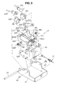
- FIG. 3 is an exploded view of a gear-shifting mechanism mounted in the hydraulically driven vehicle.
- FIG. 4 is a side view of the gear-shifting mechanism;
- FIG. 5 is a plan view of the gear-shifting mechanism;
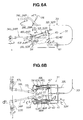
- FIGS. 6A through 6D are views showing the correlation between a speed setting device and the gear-shifting mechanism;
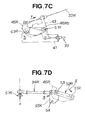
- FIGS. 7A through 7D are views showing the correlation between steering devices and the gear-shifting mechanism;
- FIG. 8 is a view showing an operation of the gear-shifting mechanism pertaining to forward movement and steering;
- FIG. 9 is a view showing a manner in which the same steering is possible regardless of the speed of the vehicle;
- FIG. 10 is a view showing an operation of the gear-shifting mechanism in a case in which the speed setting device is operated for reverse movement, and in a case in which one of the left and right steering devices is operated;
- FIG. 11 is a view showing the essential configuration of a conventional hydraulically driven vehicle;
- FIG. 12 is a cross-sectional view taken along line 12-12 of FIG. 11; and
- FIG. 13 is a cross-sectional view taken along line 13-13 of FIG. 12.
- In the following descriptions, the directions left and right are determined based on the manner in which the operator holds operating handles 24. The directions front and back are determined similarly.
- As shown in FIG. 1, a hydraulically driven
vehicle 10 is composed of avehicle frame 11; aloading platform 12 and anengine 13 as a drive source, both mounted on thevehicle frame 11; a lefthydrostatic transmission 14L and a righthydrostatic transmission 14R (14L is behind 14R; the relationship between L and R is the same hereinbelow as in this drawing) that are disposed below theengine 13 and are driven by the drive force of theengine 13; aleft drive wheel 17L and aright drive wheel 17R attached to the output-side shafts of thehydrostatic transmissions wheels 18 that are attached to thevehicle frame 11; drivenwheels vehicle frame 11;crawlers operating handles vehicle frame 11; aspeed setting device 26 and left andright steering devices operating handles shifting mechanism 31 disposed between thespeed setting device 26 andsteering devices hydrostatic transmissions - The
speed setting device 26 is an operating member for controlling the forward movement, stopping, and reverse movement of the vehicle in addition to speed, and is preferably embodied as a lever, for example. - The left and right
hydrostatic transmissions vehicle frame 11; and the gear-shifting mechanism 31 is disposed at the front of thevehicle frame 11, as shown in FIG. 2. Thesteering devices right operating handles vehicle frame 11, and thespeed setting device 26 is provided on theright operating handle 24R. - The
left steering device 28L and the gear-shifting mechanism 31 are connected by the aleft steering cable 32L; theright steering device 28R and the gear-shifting mechanism 31 are connected by aright steering cable 32R; and thespeed setting device 26 and gear-shifting mechanism 31 are connected by avehicle speed cable 33. - Push-
pull rods shifting mechanism 31 and the left and righthydrostatic transmissions pull rods shifting mechanism 31 to the left and righthydrostatic transmissions - The structural elements of the gear-shifting
mechanism 31 will now be described with reference to FIG. 3. - A first swinging
member 43 is attached withfirst pins base bracket 41 attached to the vehicle frame 11 (FIG. 2), as shown in FIG. 3. Thevehicle speed cable 33 is connected to anend 43a of the first swingingmember 43, and thevehicle speed cable 33 is operated by the speed setting device 26 (FIG. 2), allowing the first swinging member to swing around thefirst pins - A seesaw-shaped second left swinging
member 46L and secondright swinging member 46R are attached to the first swingingmember 43 at positions separated from thefirst pins center pin 63L of the secondleft swinging member 46L is inserted into ahole 62L formed in the distal end of the first swingingmember 43, and acenter pin 63R of the secondright swinging member 46R is inserted into ahole 62R formed in the distal end of the first swingingmember 43. - A left
resilient member 48L that exhibits a recoil or biasing action, such as a torsion spring, is attached to theleft pin 63L; and a rightresilient member 48R that exhibits a recoil or biasing action, such as a torsion spring, is attached to theright pin 63R. - The
left steering cable 32L is connected to one end 46La of the secondleft swinging member 46L, and theright steering cable 32R is connected to one end 46Ra of the secondright swinging member 46R. - A second
left pin 51L is provided to the other end 46Lb of the seesaw-shaped second left swingingmember 46L, and one end of aleft link plate 52L is connected to the secondleft pin 51L. - A second
right pin 51R is provided to the other end 46Rb of the seesaw-shaped secondright swinging member 46R, and one end of aright link plate 52R is connected to the secondright pin 51R. - A pair of left and
right drive plates shaft member 54 to thebase plate 41 so as to be capable of swinging independently of each other. - The other end of the
left link plate 52L and the left push-pull rod 34L are connected to theleft drive plate 55L. Theleft drive plate 55L is driven by theleft link plate 52L and fulfills the role of pushing and pulling the left push-pull rod 34L. - The other end of the
right link plate 52R and the right push-pull rod 34R are connected to theright drive plate 55R. Theright drive plate 55R is driven by theright link plate 52R and fulfills the role of pushing and pulling the right push-pull rod 34R. - In the gear-shifting
mechanism 31, thebase bracket 41 is fixed by a bolt to thevehicle frame 11 as shown in FIG. 4, which is a side view. Therefore, the first swingingmember 43 is swingably attached to thevehicle frame 11 by the first pins 42. The gear-shiftingmechanism 31 is sufficiently small in height, as can be clearly seen from FIG. 4. - In the gear-shifting
mechanism 31, the left push-pull rod 34L is connected to a gear-shiftingarm 57L appended to the lefthydrostatic transmission 14L (FIG. 2), and the right push-pull rod 34R is connected to a gear-shiftingarm 57R appended to the righthydrostatic transmission 14R (FIG. 2), as shown in FIG. 5, which is a plan view. The gear-shiftingmechanism 31 is sufficiently compact, as can be clearly seen from FIG. 5. - The following is a description of the action of the gear-shifting
mechanism 31 described above. - First, the correlation between the
speed setting device 26 and the gear-shiftingmechanism 31 will be described with reference to FIGS. 6A through 6D. - In FIG. 6A, the
speed setting device 26 is operated in the direction of the arrow m and is caused to pull on thevehicle speed cable 33, whereupon the first swingingmember 43 swings around thefirst pins second swinging members member 43 as the first swingingmember 43 swings in the direction of the arrow r. Thelink plates second swinging members drive plates link plates shaft member 54 of thebase bracket 41, and the left and right push-pull rods - In FIG. 6B, which is a view along the arrow b in FIG. 6A, the left and right push-
pull rods - In FIG. 6C, which is a view along the arrow c-c in FIG. 6B, when the
vehicle speed cable 33 is pulled in the direction of the arrow n, the first swingingmember 43 swings around thefirst pins second swinging members member 43 as the first swingingmember 43 swings in the direction of the arrow r. - In FIG. 6D, which is a view along the arrow d-d in FIG. 6B, the
second swinging members member 43. Thelink plates left pin 51L and the secondright pin 51R of thesecond swinging members drive plates shaft member 54 that is rotatably attached to thebase bracket 41, and the stroke s can be added to the push-pull rods - As described above, the left and right drive wheels can be driven in the same direction and at the same speed by operating the
speed setting device 26. - Next, the correlation between the
steering device 28R and the gear-shiftingmechanism 31 will be described with reference to FIGS. 7A through 7D. - In FIG. 7A, the
speed setting device 26 is operated in the same manner as in FIG. 6A. Thesteering device 28R operates in the direction of the arrow v and pulls thesteering cable 32R. The secondright swinging member 46R then swings around thepin 63R in the direction of the arrow α, and thelink plate 52R moves in the direction of the arrow β along with the swinging of the secondright swinging member 46R. - In FIG. 7B, which is a view from the arrow b in FIG. 7A, the right push-
pull rod 34R moves to the stopped position x (the details are described in FIG. 7D). As a result, the right gear-shiftingarm 57R is rotated, and the speed of the right drive wheel reaches zero. Since the rotational speed of the left drive wheel does not change, the vehicle (FIG. 2) turns to the right. - In FIG. 7C, which is a view along the arrow c-c in FIG. 7B, the second
right swinging member 46R swings around thepin 63R in the direction of the arrow α when theright steering cable 32R is pulled in the direction of the arrow f. - The first swinging
member 43 is inclined in relation to thebase bracket 41. The secondright swinging member 46R swings in the direction of the arrow α in relation to the first swingingmember 43. - In FIG. 7D, which is a view along the arrow d-d in FIG. 7B, the
right drive plate 55R is swung around theshaft member 54 in the direction of the arrow δ by apin 53 provided to thelink plate 52R. As a result, the right push-pull rod 34R returns to the stopped position x. The right drive wheel is thereby stopped. - A case of turning to the right was described above, and the
left steering device 28L (FIG. 2) may be operated in a case of turning to the left. - Next, a series of operations pertaining to stopping, moving forward, and turning will be described.
- The right drive wheel stops when the first swinging
member 43 is substantially horizontal, the secondright swinging member 46R is also substantially horizontal, theright link plate 52R has rotated counterclockwise by an amount of ∅1 from a horizontal line i, and theright drive plate 55R is in the illustrated position, as shown in FIG. 8A. - In FIG. 8B, when the
vehicle speed cable 33 is pulled, the first swingingmember 43 rotates as shown by the arrow p, and the secondright swinging member 46R rotates as shown by the arrow r, whereupon the position of the secondright pin 51R moves far to the left. Therefore, theright link plate 52R moves as shown by the arrow t, and thedrive plate 55R is rotated as shown by the arrow u. As a result, the right drive wheel rotates in the forward direction. - While the vehicle is moving forward, the
right steering cable 32R is pulled in the direction of the arrow f, as shown in FIG. 8C. The secondright swinging member 46R then rotates as shown by the arrow α. This rotation causes the secondright pin 51R to reach substantially the same height as thepin 63R. Specifically, the secondright pin 51R moves far to the right. Thelink plate 52R moves to the right along with this movement, as shown by the arrow β. As a result, theright drive plate 55R rotates as shown by the arrow δ to the same position as thedrive plate 55R in FIG. 8A. The right drive wheel then stops, and the vehicle turns to the right because the left drive wheel is still moving forward. - The description of FIG. 8 is supplemented by FIG. 9.
- In FIG. 9A, point A indicates the
first pins 42 around which the first swingingmember 43 swings; point B indicates a lead-inpoint 71 for the steering cable provided to the first swingingmember 43; point C indicates thepin 63R, point D indicates the secondright pin 51R of thesecond swinging members tension point 72 of the steering cable; point F indicates thepin 53; point G indicates theshaft member 54; and point H indicates a connectingpoint 73 of the push-pull rods that provide output. - Specifically, the first swinging member 43 (see FIG. 8) is formed by the lines that connect points C, A, and B in the drawing; the second
right swinging member 46R (FIG. 8) is formed by the lines that connect points C, D, and E; thelink plate 52R (FIG. 8) is formed by the lines that connect points D and F; and thedrive plate 55R (FIG. 8) is formed by the lines that connect points F, G, and H. - Points A and G do not move, and all the other points move. Point H is directly related and moves quickly.
- In FIG. 9A, the first swinging member is inclined upward in relation to the horizontal line I by an angle θa of 10°.
- The entire structure is turned to the left using point A and point G as fulcra, resulting in the arrangement shown in FIG. 9B. In FIG. 9B, the angle θc is 30°. Point H is farther to the left than in FIG. 9A, and the vehicle can therefore move forward at a high speed.
- The important point herein is that when the
steering device 28R (FIG. 2) is not operated, the angles εa and εc around point C are the same. Specifically, the relationship εa = εc is maintained even if the angle θa changes. - The steering devices are operated while the vehicle performs a low-speed movement set in FIG. 9A. When the steering devices are operated, point D moves clockwise around point C.
- When point D is superposed over point A as shown in FIG. 9C, point H reaches the stopped position.
- Similarly, the steering devices are operated while the vehicle performs the high-speed movement set in FIG. 9B. When the steering devices are operated, point D moves clockwise around point C.
- When point D is superposed over point A as shown in FIG. 9D, point H reaches the stopped position.
- To achieve the state in FIG. 9C, the operating devices are laid down until the angle εa reaches 0. Also, to achieve the state in FIG. 9D, the operating devices are laid down until the angle εc reaches 0. The operating devices are operated by the same amount because εa = εc.
- Specifically, the operating devices are operated by the same amount whether the vehicle is moving forward at a high or low speed, or in reverse at a high or low speed. As a result, driving the vehicle is extremely simple because the vehicle can be turned regardless of speed.
- The operating devices are successfully operated by the same amount regardless of speed. This is achieved by superposing point A over point D; i.e., by superposing the position of the second
right pin 51R over the axial center of the first pins 42. - Moving forward and stopping were described above, and moving in reverse will now be described.
- In FIG. 10A, when the
speed setting device 26 is operated in the direction of the arrow w and is caused to push thevehicle speed cable 33, the first swingingmember 43 swings around thefirst pins second swinging members member 43. - The
link plates left pin 51L and the secondright pin 51R provided to the other ends 46Lb, 46Rb of thesecond swinging members drive plates pins link plates pull rods - In FIG. 10B, for example, when the
right steering device 28R is operated in the direction of the arrow y and is caused to pull on theright steering cable 32R while the vehicle is moving in reverse as shown in FIG. 10A, the secondright swinging member 46R swings around thepin 63R in the direction of the arrow i. The swinging of the secondright swinging member 46R moves thelink plate 52R in the direction of the arrow j. Theright drive plate 55R is driven by thelink plate 52R, and the right push-pull rod 34R moves to the stopped position x. - Therefore, the second
right pin 51R provided to the other end 46Rb of the second right swinging member is configured so as to move to a position superposed over the first pins, and the gear-shiftingarm 57R can therefore be returned to the stopped position x via thedrive plate 55R. - The present invention was applied to a hydraulically driven vehicle equipped with crawlers in the present embodiment, but may also be applied to a three- or four-wheel hydraulically driven vehicle.
- A hydraulically driven vehicle is disclosed which is moved or turned by driving left and right hydraulic transmissions with one engine and driving left and right drive wheels with these hydraulic transmissions. The vehicle includes a gear-shifting mechanism (31) for converting the actions of an operator and transmitting the result to the hydraulic transmissions, which mechanism is comprised of a first swinging member (43) that is swung by a vehicle speed cable (33), and left and right second swinging members (46L, 46R) that are placed on the first swinging member, that are swung by left and right steering cables (32L, 32R), and that push and pull push-pull rods (34L, 34R).
Claims (2)
- A hydraulically driven vehicle comprising an engine (13) mounted on a vehicle frame (11), a left hydrostatic transmission (14L) that is driven by the engine and that drives a left drive wheel (17L), a right hydrostatic transmission (14R) that is driven by the engine and that drives a right drive wheel (17R), and a gear-shifting mechanism (31) for transmitting to the hydrostatic transmissions the movement of a speed setting device (26) that is operated by an operator to adjust the traveling speed of the vehicle frame, and the movement of left and right steering devices (28L, 28R) that are operated by the operator to turn the vehicle frame, the gear-shifting mechanism (31) comprising:a first swinging member (43) that is swingably attached to the vehicle frame with left and right first pins (42) and that is moved by the speed setting device;a left second swinging member (46L) that is swingably attached to the first swinging member at a position away from the left and right first pins and that is moved by the left steering device connected at one end (46La);a left resilient member (48L) that urges the left second swinging member into the first swinging member so that the left second swinging member swings together with the first swinging member when the left steering device is not operating;a right second swinging member (46R) that is rotatably attached to the first swinging member at a position away from the left and right first pins and that is moved by the right steering device connected to one end (46Ra);a right resilient member (48R) that urges the right second swinging member into the first swinging member so that the right second swinging member swings together with the first swinging member when the right steering device is not operating;a left drive plate (55L) swingably attached to the vehicle frame to control the left hydrostatic transmission;a left link plate (52L) that connects the left drive plate to the other end of the left second swinging member;a right drive plate (55R) swingably attached to the vehicle frame to control the right hydrostatic transmission; anda right link plate (52R) that connects the right drive plate to the other end of the right second swinging member,wherein the speed setting device is operated to incline the first swinging member and to simultaneously incline the left and right drive plates, whereby a high forward speed, a high low speed, stopping, a low reverse speed, and a high reverse speed can be arbitrarily set, and the left steering device can be operated to return the left drive plate to the stopped position, and the right steering device can be operated to return the right drive plate to the stopped position when the first swinging member is inclined.
- The hydraulically driven vehicle of claim 1, wherein the left second swinging member is connected by a left second pin (51L) to one end of the first swinging member, the right second swinging member is connected by a right second pin (51R) to one end of the first swinging member, and the position of the left second pin is set in the left second swing member while the position of the right second pin is set in the right second swinging member so that the axial center of the left second pin or the axial center of the right second pin is superposed over the axial center of the left or right first pin when the swinging members are operated by the steering devices.
Applications Claiming Priority (1)
| Application Number | Priority Date | Filing Date | Title |
|---|---|---|---|
| JP2006106515A JP4795835B2 (en) | 2006-04-07 | 2006-04-07 | Hydraulic drive vehicle |
Publications (2)
| Publication Number | Publication Date |
|---|---|
| EP1842763A1 true EP1842763A1 (en) | 2007-10-10 |
| EP1842763B1 EP1842763B1 (en) | 2008-10-15 |
Family
ID=38180150
Family Applications (1)
| Application Number | Title | Priority Date | Filing Date |
|---|---|---|---|
| EP07007084A Ceased EP1842763B1 (en) | 2006-04-07 | 2007-04-04 | Hydraulically driven vehicle |
Country Status (9)
| Country | Link |
|---|---|
| US (1) | US7789173B2 (en) |
| EP (1) | EP1842763B1 (en) |
| JP (1) | JP4795835B2 (en) |
| KR (1) | KR20070100653A (en) |
| CN (1) | CN100551734C (en) |
| AU (1) | AU2007201495B2 (en) |
| CA (1) | CA2583394C (en) |
| DE (1) | DE602007000171D1 (en) |
| TW (1) | TWI330148B (en) |
Families Citing this family (7)
| Publication number | Priority date | Publication date | Assignee | Title |
|---|---|---|---|---|
| JP4299221B2 (en) * | 2004-10-29 | 2009-07-22 | 本田技研工業株式会社 | Steering device for work equipment |
| WO2010019770A2 (en) * | 2008-08-15 | 2010-02-18 | Vermeer Manufacturing Company | Control system for a work unit |
| CN102795215B (en) * | 2012-09-10 | 2014-11-05 | 汶上弘德工程机械有限公司 | Double-linkage hydraulic control device |
| CN104871738B (en) * | 2015-04-23 | 2017-01-25 | 洛阳理工学院 | Hydraulic operating handle for farm machinery |
| CN106976481B (en) * | 2017-03-29 | 2022-11-11 | 星光农机股份有限公司 | Steering transmission structure |
| CN106965854B (en) * | 2017-03-29 | 2022-11-11 | 星光农机股份有限公司 | Transmission control device |
| CN108639143B (en) * | 2018-07-10 | 2023-08-01 | 江西良田农业机械有限公司 | Walking steering control device of harvester |
Citations (2)
| Publication number | Priority date | Publication date | Assignee | Title |
|---|---|---|---|---|
| JPH07309149A (en) | 1994-05-18 | 1995-11-28 | Honda Motor Co Ltd | Operating device for hydraulically driven vehicles |
| EP0869048A2 (en) * | 1997-03-31 | 1998-10-07 | Honda Giken Kogyo Kabushiki Kaisha | Speed change operation device for vehicle |
Family Cites Families (17)
| Publication number | Priority date | Publication date | Assignee | Title |
|---|---|---|---|---|
| JPH0735823Y2 (en) * | 1987-10-08 | 1995-08-16 | セイレイ工業株式会社 | Power transmission device |
| US5094326A (en) * | 1990-09-24 | 1992-03-10 | Simplicity Manufacturing, Inc. | Control linkage for hydrostatic transmission |
| JP3017576B2 (en) * | 1991-10-04 | 2000-03-13 | 株式会社クボタ | Walking type work machine |
| DE19636506B4 (en) * | 1996-09-09 | 2005-08-11 | Daimlerchrysler Ag | Switching device for a gear change transmission of a motor vehicle |
| JPH1084748A (en) * | 1996-09-10 | 1998-04-07 | Kubota Corp | Operation structure of combine |
| JPH10273066A (en) * | 1997-03-31 | 1998-10-13 | Honda Motor Co Ltd | Gearshift operating device for vehicles with continuously variable transmission |
| JP3266830B2 (en) * | 1997-07-16 | 2002-03-18 | 株式会社クボタ | Work equipment steering system |
| JPH1149018A (en) * | 1997-07-30 | 1999-02-23 | Yanmar Agricult Equip Co Ltd | Combine |
| US6523635B1 (en) * | 1999-11-02 | 2003-02-25 | Deere & Company | Steering and ground speed control mechanism of a dual-path hydrostatic drive system |
| US6581704B2 (en) * | 2001-06-21 | 2003-06-24 | Deere & Company | Steering controls |
| US6962219B2 (en) * | 2001-09-17 | 2005-11-08 | Mtd Products Inc | Mechanical ZTR system with steering wheel |
| US6904985B2 (en) * | 2003-05-21 | 2005-06-14 | Deere & Company | Transmission control device for vehicles and steering assembly for vehicles |
| US7467677B2 (en) * | 2004-02-23 | 2008-12-23 | Barrier Scott D | Control mechanism for zero turning radius mower |
| US7270200B2 (en) * | 2004-08-31 | 2007-09-18 | Iseki & Co., Ltd. | Working vehicle |
| JP4299221B2 (en) * | 2004-10-29 | 2009-07-22 | 本田技研工業株式会社 | Steering device for work equipment |
| JP4436232B2 (en) * | 2004-10-29 | 2010-03-24 | 本田技研工業株式会社 | Steering device for work equipment |
| US7478689B1 (en) * | 2006-03-21 | 2009-01-20 | Scag Power Equipment, Inc. | Vehicle steering and speed control |
-
2006
- 2006-04-07 JP JP2006106515A patent/JP4795835B2/en not_active Expired - Fee Related
-
2007
- 2007-03-30 US US11/731,544 patent/US7789173B2/en not_active Expired - Fee Related
- 2007-03-30 CA CA2583394A patent/CA2583394C/en not_active Expired - Fee Related
- 2007-03-30 TW TW096111483A patent/TWI330148B/en active
- 2007-04-04 AU AU2007201495A patent/AU2007201495B2/en not_active Ceased
- 2007-04-04 DE DE602007000171T patent/DE602007000171D1/en active Active
- 2007-04-04 EP EP07007084A patent/EP1842763B1/en not_active Ceased
- 2007-04-06 KR KR1020070033925A patent/KR20070100653A/en not_active Ceased
- 2007-04-06 CN CNB2007100910685A patent/CN100551734C/en not_active Expired - Fee Related
Patent Citations (2)
| Publication number | Priority date | Publication date | Assignee | Title |
|---|---|---|---|---|
| JPH07309149A (en) | 1994-05-18 | 1995-11-28 | Honda Motor Co Ltd | Operating device for hydraulically driven vehicles |
| EP0869048A2 (en) * | 1997-03-31 | 1998-10-07 | Honda Giken Kogyo Kabushiki Kaisha | Speed change operation device for vehicle |
Also Published As
| Publication number | Publication date |
|---|---|
| AU2007201495B2 (en) | 2009-03-12 |
| JP2007276666A (en) | 2007-10-25 |
| KR20070100653A (en) | 2007-10-11 |
| TW200808580A (en) | 2008-02-16 |
| TWI330148B (en) | 2010-09-11 |
| EP1842763B1 (en) | 2008-10-15 |
| CN100551734C (en) | 2009-10-21 |
| US7789173B2 (en) | 2010-09-07 |
| US20070235232A1 (en) | 2007-10-11 |
| DE602007000171D1 (en) | 2008-11-27 |
| CA2583394A1 (en) | 2007-10-07 |
| CN101049802A (en) | 2007-10-10 |
| CA2583394C (en) | 2013-04-30 |
| AU2007201495A1 (en) | 2007-10-25 |
| JP4795835B2 (en) | 2011-10-19 |
Similar Documents
| Publication | Publication Date | Title |
|---|---|---|
| EP1842763B1 (en) | Hydraulically driven vehicle | |
| US20090250270A1 (en) | Steering and Driving Systems and Related Vehicles | |
| US7059434B2 (en) | Hand controls for small loader | |
| US4043416A (en) | Skid-steered tractor vehicle combined steering lever and auxiliary control with self-centering mechanism | |
| US3938401A (en) | Two-speed motor control for dual hydrostatic transmissions | |
| EP3421283A1 (en) | Working vehicle | |
| US3850258A (en) | Control lever friction clutch | |
| US3968706A (en) | Two-speed motor control for dual hydrostatic transmissions | |
| JP4634972B2 (en) | Work vehicle travel control device | |
| JP2003002228A (en) | Tractor | |
| JP4838057B2 (en) | Shift operating device for work vehicle | |
| JP2009035087A (en) | Working vehicle | |
| JPH09286345A (en) | Steering control device for hst running device | |
| JP4116389B2 (en) | HST transmission structure of traveling vehicle | |
| JP3411432B2 (en) | Work vehicle operation control structure | |
| JP4157401B2 (en) | snowblower | |
| JP2000335458A (en) | Traveling device | |
| JPH1084748A (en) | Operation structure of combine | |
| JP2004090799A (en) | Steering operation structure of work equipment | |
| JPH07232660A (en) | Driving device for hydraulically-driven vehicle | |
| JP2006336721A (en) | Work vehicle | |
| JP2002068008A (en) | Transmission for riding working vehicle | |
| JPH0899649A (en) | Maneuvering device for hydraulically operared vehicle | |
| JP2008143223A (en) | Working vehicle | |
| JPH10278616A (en) | Gear shift device of work machine |
Legal Events
| Date | Code | Title | Description |
|---|---|---|---|
| PUAI | Public reference made under article 153(3) epc to a published international application that has entered the european phase |
Free format text: ORIGINAL CODE: 0009012 |
|
| 17P | Request for examination filed |
Effective date: 20070404 |
|
| AK | Designated contracting states |
Kind code of ref document: A1 Designated state(s): AT BE BG CH CY CZ DE DK EE ES FI FR GB GR HU IE IS IT LI LT LU LV MC MT NL PL PT RO SE SI SK TR |
|
| AX | Request for extension of the european patent |
Extension state: AL BA HR MK YU |
|
| GRAP | Despatch of communication of intention to grant a patent |
Free format text: ORIGINAL CODE: EPIDOSNIGR1 |
|
| GRAS | Grant fee paid |
Free format text: ORIGINAL CODE: EPIDOSNIGR3 |
|
| AKX | Designation fees paid |
Designated state(s): DE FR GB IT |
|
| GRAA | (expected) grant |
Free format text: ORIGINAL CODE: 0009210 |
|
| AK | Designated contracting states |
Kind code of ref document: B1 Designated state(s): DE FR GB IT |
|
| REG | Reference to a national code |
Ref country code: GB Ref legal event code: FG4D |
|
| REF | Corresponds to: |
Ref document number: 602007000171 Country of ref document: DE Date of ref document: 20081127 Kind code of ref document: P |
|
| PLBE | No opposition filed within time limit |
Free format text: ORIGINAL CODE: 0009261 |
|
| STAA | Information on the status of an ep patent application or granted ep patent |
Free format text: STATUS: NO OPPOSITION FILED WITHIN TIME LIMIT |
|
| 26N | No opposition filed |
Effective date: 20090716 |
|
| PG25 | Lapsed in a contracting state [announced via postgrant information from national office to epo] |
Ref country code: IT Free format text: LAPSE BECAUSE OF NON-PAYMENT OF DUE FEES Effective date: 20100404 |
|
| REG | Reference to a national code |
Ref country code: FR Ref legal event code: PLFP Year of fee payment: 10 |
|
| REG | Reference to a national code |
Ref country code: FR Ref legal event code: PLFP Year of fee payment: 11 |
|
| PGFP | Annual fee paid to national office [announced via postgrant information from national office to epo] |
Ref country code: FR Payment date: 20170313 Year of fee payment: 11 |
|
| PGFP | Annual fee paid to national office [announced via postgrant information from national office to epo] |
Ref country code: GB Payment date: 20170329 Year of fee payment: 11 |
|
| PGFP | Annual fee paid to national office [announced via postgrant information from national office to epo] |
Ref country code: DE Payment date: 20170329 Year of fee payment: 11 |
|
| PGFP | Annual fee paid to national office [announced via postgrant information from national office to epo] |
Ref country code: IT Payment date: 20170420 Year of fee payment: 11 |
|
| REG | Reference to a national code |
Ref country code: DE Ref legal event code: R119 Ref document number: 602007000171 Country of ref document: DE |
|
| GBPC | Gb: european patent ceased through non-payment of renewal fee |
Effective date: 20180404 |
|
| PG25 | Lapsed in a contracting state [announced via postgrant information from national office to epo] |
Ref country code: DE Free format text: LAPSE BECAUSE OF NON-PAYMENT OF DUE FEES Effective date: 20181101 |
|
| PG25 | Lapsed in a contracting state [announced via postgrant information from national office to epo] |
Ref country code: GB Free format text: LAPSE BECAUSE OF NON-PAYMENT OF DUE FEES Effective date: 20180404 |
|
| PG25 | Lapsed in a contracting state [announced via postgrant information from national office to epo] |
Ref country code: FR Free format text: LAPSE BECAUSE OF NON-PAYMENT OF DUE FEES Effective date: 20180430 Ref country code: IT Free format text: LAPSE BECAUSE OF NON-PAYMENT OF DUE FEES Effective date: 20180404 |