EP1842759A2 - Stroller - Google Patents
Stroller Download PDFInfo
- Publication number
- EP1842759A2 EP1842759A2 EP07075248A EP07075248A EP1842759A2 EP 1842759 A2 EP1842759 A2 EP 1842759A2 EP 07075248 A EP07075248 A EP 07075248A EP 07075248 A EP07075248 A EP 07075248A EP 1842759 A2 EP1842759 A2 EP 1842759A2
- Authority
- EP
- European Patent Office
- Prior art keywords
- stroller
- connecting element
- frame
- wheels
- movement
- Prior art date
- Legal status (The legal status is an assumption and is not a legal conclusion. Google has not performed a legal analysis and makes no representation as to the accuracy of the status listed.)
- Granted
Links
- 239000000463 material Substances 0.000 claims description 4
- 230000001154 acute effect Effects 0.000 claims description 3
- 230000005540 biological transmission Effects 0.000 description 5
- 238000010276 construction Methods 0.000 description 2
- 239000002184 metal Substances 0.000 description 2
- 230000006835 compression Effects 0.000 description 1
- 238000007906 compression Methods 0.000 description 1
- 230000005489 elastic deformation Effects 0.000 description 1
- 230000000717 retained effect Effects 0.000 description 1
Images



Classifications
-
- B—PERFORMING OPERATIONS; TRANSPORTING
- B62—LAND VEHICLES FOR TRAVELLING OTHERWISE THAN ON RAILS
- B62B—HAND-PROPELLED VEHICLES, e.g. HAND CARTS OR PERAMBULATORS; SLEDGES
- B62B7/00—Carriages for children; Perambulators, e.g. dolls' perambulators
- B62B7/04—Carriages for children; Perambulators, e.g. dolls' perambulators having more than one wheel axis; Steering devices therefor
Definitions
- the invention relates to a stroller comprising a frame and wheels supporting the frame, which stroller can at least be wheeled over a ground surface in a horizontal direction of movement, wherein at least two wheels are interconnected by a connecting element which is pivotable with respect to the frame about a pivot axis that extends at an angle to the horizontal, which wheels are movable in opposite vertical directions and in opposite horizontal directions parallel to a direction of movement of the stroller upon pivoting of the connecting element.
- the object of the invention is to provide a stroller in which an improved transmission of the forces exerted on the stroller and an improved positioning of the wheels is realised.
- first wheel When a first wheel comes into contact with an obstacle, said first wheel is moved in a horizontal direction opposite to the direction of movement and a vertical direction away from the ground surface as a result of said pivoting of the connecting element, whilst the other, second wheel is moved horizontally in the direction of movement with respect to the frame and is pressed more firmly against the ground surface.
- the first wheel can readily move over the obstacle.
- the wheels can also pivot about the vertical pivot axes in a direction opposite to the direction of pivoting of the connecting element, so that the direction of movement of the wheels will remain unchanged.
- the wheel Since the wheel is movable not only in vertical direction but also in horizontal direction, a better transmission of forces is obtained when a wheel hits an obstacle present on the ground surface.
- Yet another embodiment of the stroller according to the invention is characterised in that the pivot axis includes an angle of at least 20 degrees with the horizontal.
- Yet another embodiment of the stroller according to the invention is characterised in that the pivot axis includes an acute angle with the horizontal, seen in the direction of movement.
- one wheel When such an acute at angle is used, one wheel will be moved in a vertical direction away from the ground surface and a horizontal direction opposite to the direction of movement, whilst the other wheel will be moved in the opposite direction. In this way an efficient transmission of forces is obtained.
- Yet another embodiment of the stroller according to the invention is characterised in that the connecting element is pivotally connected to the frame against spring force.
- the starting position of the connecting element will be such that the wheels are identically oriented with respect to the frame. Only in the case of a force being exerted on one of the wheels will the connecting element pivot against said spring force. Once said force is released, the connecting element will pivot back to the starting position under the influence of the spring force.
- the connecting element comprises an unround shaft which is pivotally journalled in an unround opening in a material that is elastically deformable against spring force.
- the connecting element is spring-connected to the frame in a relatively simple manner.
- the elastically deformable material preferably comprises rubber.
- the connecting element may also be spring-connected to the frame by means of a leaf spring or a spiral spring. Such springs, too, can be realised in a relatively simple manner.
- Another embodiment of the stroller according to the invention is characterised in that the connecting element is detachably connected to the frame.
- the connecting element and the wheels connected thereto can be readily detached from the frame, after which the frame is preferably collapsible, so that the frame and the connecting element that has been detached therefrom can easily be transported, for example in a car.
- Yet another embodiment of the stroller according to the invention is characterised in that the wheels connected to the connecting element are the front wheels of the stroller, seen in the direction of movement.
- the front wheels of the stroller are the wheels that first come into contact with an obstacle present on the ground surface. Since said wheels are connected to the connecting element, an efficient transmission of the forces being exerted on the stroller is obtained. It is also possible, of course, to provide the rear wheels of the stroller, seen in the direction of movement, with such a connecting element or to provide both the front wheels and the rear wheels with a connecting element.
- a further embodiment of the stroller according to the invention is characterised in that the wheel is simultaneously movable in a vertical direction away from the ground surface and a horizontal direction opposite to the direction of movement.
- Another embodiment of the stroller according to the invention is characterised in that the wheel is movable against spring force.
- the wheel will be moved against spring force with respect to the frame upon hitting an obstacle, and subsequently the wheel will be returned to its original starting position under the influence of spring force.
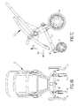
- FIGS 1A-1C are a perspective view, a front view and a side view, respectively, of a stroller 1 according to the invention, which comprises a frame 2, a seat 3 supported by the frame 2 and detachably connected thereto, a pair of rear wheels 4, 5 and a pair of front wheels 6, 7.
- the rear wheels 4, 5 and the front wheels 6, 7 support the frame 2.
- the front wheels 6, 7 are pivotally connected about vertically extending pivot axes 8, 9 to a rod 10, which extends substantially transversely to the direction of movement of the stroller indicated by the arrow P1.
- the rod 10 forms a connecting element for interconnecting the front wheels 6, 7.
- the frame 2 comprises a section 11 extending in the direction of movement indicated by the arrow P1, which section is provided with a connecting element 12 at an end located near the front wheels 6, 7, to which connecting element 12 the rod 10 can be detachably connected.
- the rod 10 is pivotable about a pivot axis 13 with respect to the connecting element 12 in the direction indicated by the arrow P2 and in the opposite direction. Pivoting of the rod 10 about the pivot axis 13 causes the wheels 6, 7 to be moved with respect to the frame 2 in the horizontal direction indicated by the arrow P2 and in the opposite direction and in the vertical direction indicated by the arrow P3 and in the opposite direction.
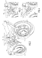
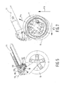
- FIGs 2-5 show an embodiment of the connection of the rod 10 to the connecting element 12 of a stroller 1 according to the invention.
- the connecting element 12 comprises two spaced-apart annular elements 14, 15 and a rubber block 16 that can be positioned between said annular elements 14, 15.
- the rubber block 16 is provided with a square passage 17, in which a U-shaped metal section 18 is positioned. Legs 19 of the U-shaped section 18 extend into gaps 20 that connect to the square passage 17. As a result, the U-shaped section 18 is adequately locked in position in the rubber element 16.
- the rod 10 is provided with a pin 21 extending parallel to the pivot axis 13, which pin comprises a circular cylindrical part 22 and a square part 23 located between the circular cylindrical part 22 and the rod.
- the dimensions of the square part 23 are such that it fits in the square passage 17 defined by the rubber element 16 and the U-shaped section 18.
- the pin 21 can be inserted into the annular element 14 until the part 22 is positioned in the opening 24 in the annular part 15 and the square part 23 is positioned in the square passage 17.
- the pin 21 is retained in the position thus obtained by means of a locking pawl 25.
- the circular cylindrical part 22 can pivot in the opening 24 in the direction indicated by the arrow P2 and in the opposite direction. During said pivoting, the square part 22 exerts a force on the metal U-shaped part 18, resulting in elastic deformation of the rubber element 16.
- Figures 6A-6C and figure 7 show a situation in which the front wheel 7 comes into contact with an obstacle present on a ground surface, as a result of which a force is exerted on the front wheel 7 in a direction opposite to the direction indicated by the arrow P1 and in the direction indicated by the arrow P3.
- the resultant of said force extends in the direction indicated by the arrow P4 (see figure 7).
- the wheel 7 is moved in said direction, whilst the rod 10 pivots in the direction indicated by the arrow P2 and the wheel 6 is moved in a direction opposite to the direction of movement of the wheel 7.
- the wheel that comes into contact with an obstacle is moved in a direction away from the ground surface and in a direction opposite to the direction of movement, whilst the other wheel is moved in the direction of movement and in a direction towards the ground surface. In this way the stroller is moved over the obstacle in a simple manner.
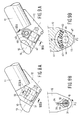
- Figures 8A hand 8B show another embodiment of a spring connection of the rod 3 to the connecting element 12.
- the rod 3 is provided with a pin 31, which extends through an opening 32 in the connecting element 12.
- the pin 31 is provided with a leaf spring 33 extending transversely to the pin 31, which leaf spring is positioned in a chamber 34 of the opening 32 with a side remote from the pin 31.
- the leaf spring 33 will deform when the rod 10 and the pin 31 connected thereto pivot in the direction indicated by the arrow P2 or in the opposite direction and slide along a wall 35 of the openings 32. Once the forces being exerted on the stroller and 1 are released, the rod 10 will return to the position shown in figure 8B under the influence of the spring force of the leaf spring 33.
- FIGS 9A and 9B show yet another embodiment of a spring connection between the rod 10 and the connecting element 12.
- the connecting element 12 comprises a chamber 41, in which two spiral springs 42, 43 are positioned.
- the spiral springs 42, 43 abut against the walls 44, 45 of the chamber 41 with one end and against a plate 46 with an end remote from the walls 44, 45.
- the plate 46 forms part of a pin 47 that is connected to the rod 10. Pivoting of the rod 10 and the pin 47 connected thereto in the direction indicated by the arrow P2 or in the opposite direction results in compression of one spiral spring 43, 44 and extension of the other spiral spring 43, 44.
- the rod 10 will return to the starting position shown in figures 1A-1C under the influence of the spring force of the springs 43, 43.
- each wheel 6, 7 is pivotable about the pivot axis 13 by means of separate connecting elements 12.
Landscapes
- Engineering & Computer Science (AREA)
- Chemical & Material Sciences (AREA)
- Combustion & Propulsion (AREA)
- Transportation (AREA)
- Mechanical Engineering (AREA)
- Carriages For Children, Sleds, And Other Hand-Operated Vehicles (AREA)
- Handcart (AREA)
Abstract
Description
- The invention relates to a stroller comprising a frame and wheels supporting the frame, which stroller can at least be wheeled over a ground surface in a horizontal direction of movement, wherein at least two wheels are interconnected by a connecting element which is pivotable with respect to the frame about a pivot axis that extends at an angle to the horizontal, which wheels are movable in opposite vertical directions and in opposite horizontal directions parallel to a direction of movement of the stroller upon pivoting of the connecting element.
- With such a stroller, which is known from
DE-A1-198.29.076 , an inner front wheel is moved slightly rearwards, seen in the direction of movement, and upwards, seen in vertical direction, with respect to the frame when the stroller is moved round a bend, whilst the outer front wheel is moved slightly forwards, seen in the direction of movement, and downwards, seen in vertical direction. As a result, the stroller will take up an inclined position in the bend. - It has been found, however, that when one of the front wheels, for example, comes into contact with an obstacle present on the ground surface upon movement of the stroller in a horizontal, forward direction, a horizontal force is exerted on the stroller via said front wheel, which force is converted by the connecting element into a movement of the wheels that corresponds to the movement of a stroller round a bend whereby the wheels also partly pivot about the vertical. This makes it difficult to move the stroller in a straight line, especially if obstacles are present on the ground surface.
- The object of the invention is to provide a stroller in which an improved transmission of the forces exerted on the stroller and an improved positioning of the wheels is realised.
- This object is accomplished with the stroller according to the invention in that the wheels are pivotable with respect to the connecting element about substantially vertically extending pivot axes.
- When a first wheel comes into contact with an obstacle, said first wheel is moved in a horizontal direction opposite to the direction of movement and a vertical direction away from the ground surface as a result of said pivoting of the connecting element, whilst the other, second wheel is moved horizontally in the direction of movement with respect to the frame and is pressed more firmly against the ground surface. As a result, the first wheel can readily move over the obstacle. Upon doing so, the wheels can also pivot about the vertical pivot axes in a direction opposite to the direction of pivoting of the connecting element, so that the direction of movement of the wheels will remain unchanged.
- Since the wheel is movable not only in vertical direction but also in horizontal direction, a better transmission of forces is obtained when a wheel hits an obstacle present on the ground surface.
- Since the wheels are pivotable about vertically extending pivot axes, turning the stroller about a vertically extending axis when going round a bend is moreover comparatively easy.
- Yet another embodiment of the stroller according to the invention is characterised in that the pivot axis includes an angle of at least 20 degrees with the horizontal.
- When such an angle is used, an advantageous relation is obtained between the horizontal movement and the vertical movement of each wheel.
- Yet another embodiment of the stroller according to the invention is characterised in that the pivot axis includes an acute angle with the horizontal, seen in the direction of movement.
- When such an acute at angle is used, one wheel will be moved in a vertical direction away from the ground surface and a horizontal direction opposite to the direction of movement, whilst the other wheel will be moved in the opposite direction. In this way an efficient transmission of forces is obtained.
- Yet another embodiment of the stroller according to the invention is characterised in that the connecting element is pivotally connected to the frame against spring force.
- As a result of the spring force, the starting position of the connecting element will be such that the wheels are identically oriented with respect to the frame. Only in the case of a force being exerted on one of the wheels will the connecting element pivot against said spring force. Once said force is released, the connecting element will pivot back to the starting position under the influence of the spring force.
- Another embodiment of the stroller according to the invention is characterised in that the connecting element comprises an unround shaft which is pivotally journalled in an unround opening in a material that is elastically deformable against spring force.
- As a result, the connecting element is spring-connected to the frame in a relatively simple manner.
- The elastically deformable material preferably comprises rubber.
- The connecting element may also be spring-connected to the frame by means of a leaf spring or a spiral spring. Such springs, too, can be realised in a relatively simple manner.
- Another embodiment of the stroller according to the invention is characterised in that the connecting element is detachably connected to the frame.
- In this way the connecting element and the wheels connected thereto can be readily detached from the frame, after which the frame is preferably collapsible, so that the frame and the connecting element that has been detached therefrom can easily be transported, for example in a car.
- Yet another embodiment of the stroller according to the invention is characterised in that the wheels connected to the connecting element are the front wheels of the stroller, seen in the direction of movement.
- The front wheels of the stroller are the wheels that first come into contact with an obstacle present on the ground surface. Since said wheels are connected to the connecting element, an efficient transmission of the forces being exerted on the stroller is obtained. It is also possible, of course, to provide the rear wheels of the stroller, seen in the direction of movement, with such a connecting element or to provide both the front wheels and the rear wheels with a connecting element.
- A further embodiment of the stroller according to the invention is characterised in that the wheel is simultaneously movable in a vertical direction away from the ground surface and a horizontal direction opposite to the direction of movement.
- As soon as the wheel comes into contact with an obstacle present on the ground surface, a force will be exerted on the wheel in a horizontal direction opposite to the direction of movement. This causes the wheel to move in that direction, but the wheel will simultaneously be moved in a vertical direction away from the ground surface, as a result of which the wheel is moved over said obstacle. In this way an advantageous transmission of forces is obtained.
- Another embodiment of the stroller according to the invention is characterised in that the wheel is movable against spring force.
- As a result, the wheel will be moved against spring force with respect to the frame upon hitting an obstacle, and subsequently the wheel will be returned to its original starting position under the influence of spring force.
- The invention will now be explained in more detail with reference to the drawings, in which:
- Figures 1A-1C are a perspective view, a front view and a side view, respectively, of a stroller according to the invention;
- Figure 2 is a perspective, exploded view of a part of the stroller shown in figures 1A-1C;
- Figure 3 shows a detail of the perspective view of figure 2;
- Figure 4 is a perspective view corresponding to the detail view of figure 3, in which a few components are shown in assembled condition;
- Figure 5 is a sectional side view of a part of the stroller shown in figure 1C;
- Figures 6A-6C are a perspective view, a front view and a side view, respectively, of the stroller shown in figures 1A-1C, in which the front wheels have been moved with respect to the frame;
- Figures 7 shows a part of the side view of figure 6C;
- Figures 8A and 8B are a sectional side view and a front view in the direction indicated by the arrows VIII-VIII of an alternative embodiment of the spring-mounted construction shown in figures 2-4;
- Figures 9A and 9B are a sectional side view and a front view in the direction indicated by the arrows IX-IX of an alternative embodiment of the spring-mounted construction shown in figures 2-4.
- Like parts are indicated by the same numerals in the figures.
- Figures 1A-1C are a perspective view, a front view and a side view, respectively, of a
stroller 1 according to the invention, which comprises aframe 2, a seat 3 supported by theframe 2 and detachably connected thereto, a pair ofrear wheels 4, 5 and a pair offront wheels rear wheels 4, 5 and thefront wheels frame 2. Thefront wheels pivot axes 8, 9 to arod 10, which extends substantially transversely to the direction of movement of the stroller indicated by the arrow P1. Therod 10 forms a connecting element for interconnecting thefront wheels frame 2 comprises asection 11 extending in the direction of movement indicated by the arrow P1, which section is provided with a connectingelement 12 at an end located near thefront wheels element 12 therod 10 can be detachably connected. Therod 10 is pivotable about apivot axis 13 with respect to the connectingelement 12 in the direction indicated by the arrow P2 and in the opposite direction. Pivoting of therod 10 about thepivot axis 13 causes thewheels frame 2 in the horizontal direction indicated by the arrow P2 and in the opposite direction and in the vertical direction indicated by the arrow P3 and in the opposite direction. - Figures 2-5 show an embodiment of the connection of the
rod 10 to the connectingelement 12 of astroller 1 according to the invention. The connectingelement 12 comprises two spaced-apartannular elements rubber block 16 that can be positioned between saidannular elements rubber block 16 is provided with asquare passage 17, in which a U-shapedmetal section 18 is positioned.Legs 19 of the U-shapedsection 18 extend intogaps 20 that connect to thesquare passage 17. As a result, the U-shapedsection 18 is adequately locked in position in therubber element 16. Therod 10 is provided with apin 21 extending parallel to thepivot axis 13, which pin comprises a circularcylindrical part 22 and asquare part 23 located between the circularcylindrical part 22 and the rod. The dimensions of thesquare part 23 are such that it fits in thesquare passage 17 defined by therubber element 16 and theU-shaped section 18. After theelement 16 has been positioned between theannular elements 14, 15 (see figure 4), thepin 21 can be inserted into theannular element 14 until thepart 22 is positioned in theopening 24 in theannular part 15 and thesquare part 23 is positioned in thesquare passage 17. Thepin 21 is retained in the position thus obtained by means of alocking pawl 25. The circularcylindrical part 22 can pivot in theopening 24 in the direction indicated by the arrow P2 and in the opposite direction. During said pivoting, thesquare part 22 exerts a force on the metalU-shaped part 18, resulting in elastic deformation of therubber element 16. - Figures 6A-6C and figure 7 show a situation in which the
front wheel 7 comes into contact with an obstacle present on a ground surface, as a result of which a force is exerted on thefront wheel 7 in a direction opposite to the direction indicated by the arrow P1 and in the direction indicated by the arrow P3. The resultant of said force extends in the direction indicated by the arrow P4 (see figure 7). As a result of said force P4, thewheel 7 is moved in said direction, whilst therod 10 pivots in the direction indicated by the arrow P2 and thewheel 6 is moved in a direction opposite to the direction of movement of thewheel 7. The wheel that comes into contact with an obstacle is moved in a direction away from the ground surface and in a direction opposite to the direction of movement, whilst the other wheel is moved in the direction of movement and in a direction towards the ground surface. In this way the stroller is moved over the obstacle in a simple manner. - Figures 8A hand 8B show another embodiment of a spring connection of the rod 3 to the connecting
element 12. The rod 3 is provided with apin 31, which extends through anopening 32 in the connectingelement 12. Thepin 31 is provided with aleaf spring 33 extending transversely to thepin 31, which leaf spring is positioned in achamber 34 of theopening 32 with a side remote from thepin 31. Theleaf spring 33 will deform when therod 10 and thepin 31 connected thereto pivot in the direction indicated by the arrow P2 or in the opposite direction and slide along awall 35 of theopenings 32. Once the forces being exerted on the stroller and 1 are released, therod 10 will return to the position shown in figure 8B under the influence of the spring force of theleaf spring 33. - Figures 9A and 9B show yet another embodiment of a spring connection between the
rod 10 and the connectingelement 12. The connectingelement 12 comprises achamber 41, in which two spiral springs 42, 43 are positioned. The spiral springs 42, 43 abut against thewalls chamber 41 with one end and against aplate 46 with an end remote from thewalls plate 46 forms part of apin 47 that is connected to therod 10. Pivoting of therod 10 and thepin 47 connected thereto in the direction indicated by the arrow P2 or in the opposite direction results in compression of onespiral spring other spiral spring front wheels rod 10 will return to the starting position shown in figures 1A-1C under the influence of the spring force of thesprings - Is also possible to configure the
wheels wheel pivot axis 13 by means of separate connectingelements 12.
Claims (11)
- A stroller (1) comprising a frame (2) and wheels (4, 5: 6, 7) supporting the frame, which stroller can at least be wheeled over a ground surface in a horizontal direction of movement, wherein at least two wheels (4, 5: 6, 7) are interconnected by a connecting element (12) which is pivotable with respect to the frame about a pivot axis (13) that extends at an angle to the horizontal, which wheels (4, 5: 6, 7) are movable in opposite vertical directions and in opposite horizontal directions parallel to a direction of movement of the stroller (1) upon pivoting of the connecting element (12), characterised in that the wheels (4, 5) are pivotable with respect to the connecting element (12) about substantially vertically extending pivot axes (8, 9).
- A stroller (1) according to claim 1, characterised in that the pivot axis (13) includes an angle of at least 20 degrees with the horizontal.
- A stroller (1) according to claim 1 or 2, characterised in that the pivot axis (13) includes an acute angle with the horizontal, seen in the direction of movement.
- A stroller (1) according to any one of the preceding claims, characterised in that the connecting element (12) is pivotally connected to the frame (2) against spring force.
- A stroller (1) according to claim 4, characterised in that the connecting element (12) comprises an unround shaft (23) which is pivotally journalled in an unround opening (17) in a material that is elastically deformable against spring force.
- A stroller (1) according to claim 5, characterised in that the elastically deformable material comprises rubber.
- A stroller (1) according to any one of the preceding claims, characterised in that at least a leaf spring (33) or a spiral spring (42, 43) is provided between the connecting element (12) and the frame (2).
- A stroller (1) according to any one of the preceding claims, characterised in that the connecting element (12) is detachably connected to the frame.
- A stroller (1) according to any one of the preceding claims, characterised in that the wheels connected to the connecting element (12) are the front wheels (4, 5) of the stroller, seen in the direction of movement.
- A stroller (1) according to any one of the preceding claims, characterised in that the wheel is simultaneously movable in a vertical direction away from the ground surface and a horizontal direction opposite to the direction of movement.
- A stroller (1) according to claim 10, characterised in that the wheel is movable against spring force.
Applications Claiming Priority (1)
| Application Number | Priority Date | Filing Date | Title |
|---|---|---|---|
| NL1031517A NL1031517C2 (en) | 2006-04-05 | 2006-04-05 | Stroller. |
Publications (3)
| Publication Number | Publication Date |
|---|---|
| EP1842759A2 true EP1842759A2 (en) | 2007-10-10 |
| EP1842759A3 EP1842759A3 (en) | 2009-12-09 |
| EP1842759B1 EP1842759B1 (en) | 2014-11-19 |
Family
ID=37719258
Family Applications (1)
| Application Number | Title | Priority Date | Filing Date |
|---|---|---|---|
| EP07075248.0A Not-in-force EP1842759B1 (en) | 2006-04-05 | 2007-04-02 | Stroller |
Country Status (5)
| Country | Link |
|---|---|
| US (1) | US20070241525A1 (en) |
| EP (1) | EP1842759B1 (en) |
| CN (1) | CN101049837A (en) |
| ES (1) | ES2526445T3 (en) |
| NL (1) | NL1031517C2 (en) |
Cited By (3)
| Publication number | Priority date | Publication date | Assignee | Title |
|---|---|---|---|---|
| US8505956B2 (en) | 2009-03-23 | 2013-08-13 | Wonderland Nurserygoods Company Limited | Stroller |
| CN108552856A (en) * | 2017-12-23 | 2018-09-21 | 李洪玉 | A kind of perambulator easy to remove |
| WO2021125302A1 (en) | 2019-12-19 | 2021-06-24 | ヤマハ発動機株式会社 | Vehicle |
Families Citing this family (1)
| Publication number | Priority date | Publication date | Assignee | Title |
|---|---|---|---|---|
| US7744102B2 (en) * | 2005-07-09 | 2010-06-29 | Eric Shawn Bailey | Steerable carriage apparatus |
Citations (1)
| Publication number | Priority date | Publication date | Assignee | Title |
|---|---|---|---|---|
| DE19829076A1 (en) | 1997-07-08 | 1999-01-28 | Michael Kientzler | Personal transport equipment, particularly baby carriage/perambulator |
Family Cites Families (11)
| Publication number | Priority date | Publication date | Assignee | Title |
|---|---|---|---|---|
| SE511894C2 (en) * | 1998-11-24 | 1999-12-13 | Hassan Ahmad | Device at a stroller |
| NL1017961C1 (en) * | 2000-07-26 | 2002-02-08 | Mutsy Bv | Baby carriage with steerable wheels. |
| AU2001286047A1 (en) * | 2000-09-04 | 2002-03-22 | Geoffrey Wilfred Barley | Improvements relating to support systems |
| CA2318028C (en) * | 2000-09-12 | 2005-08-09 | Random Products Trust | Combination walker and transport chair |
| US6443467B1 (en) * | 2000-09-22 | 2002-09-03 | Racing Strollers, Inc. | Baby stroller with interchangeable front wheel support structures |
| FR2839935B1 (en) * | 2002-05-21 | 2005-01-07 | Ampafrance | STROLLER FOR CHILDREN, FRONT TRAIN SUSPENDED AND DIRECTIONAL |
| US6663122B1 (en) * | 2002-07-18 | 2003-12-16 | Wan-Hsing Lin | Stroller frame |
| DE10329092A1 (en) * | 2003-06-27 | 2005-01-20 | Hauck Gmbh & Co Kg | Stroller with wheels pivotable against an elastic return element |
| US7118116B2 (en) * | 2004-01-30 | 2006-10-10 | Wang-Hsing Lin | Stroller having front wheels that can be turned stably and smoothly |
| DE202004012083U1 (en) | 2004-08-02 | 2004-12-16 | Hauck Gmbh & Co. Kg | Collapsible push chair with front and/or rear axle pivoted about horizontal axis, and esp. font wheels pivoted about vertical axis |
| US20060255564A1 (en) * | 2005-05-12 | 2006-11-16 | Bayre Design | Steerable wheeled cart |
-
2006
- 2006-04-05 NL NL1031517A patent/NL1031517C2/en not_active IP Right Cessation
-
2007
- 2007-04-02 ES ES07075248.0T patent/ES2526445T3/en active Active
- 2007-04-02 EP EP07075248.0A patent/EP1842759B1/en not_active Not-in-force
- 2007-04-04 US US11/696,590 patent/US20070241525A1/en not_active Abandoned
- 2007-04-05 CN CNA2007100937264A patent/CN101049837A/en active Pending
Patent Citations (1)
| Publication number | Priority date | Publication date | Assignee | Title |
|---|---|---|---|---|
| DE19829076A1 (en) | 1997-07-08 | 1999-01-28 | Michael Kientzler | Personal transport equipment, particularly baby carriage/perambulator |
Cited By (4)
| Publication number | Priority date | Publication date | Assignee | Title |
|---|---|---|---|---|
| US8505956B2 (en) | 2009-03-23 | 2013-08-13 | Wonderland Nurserygoods Company Limited | Stroller |
| CN108552856A (en) * | 2017-12-23 | 2018-09-21 | 李洪玉 | A kind of perambulator easy to remove |
| CN108552856B (en) * | 2017-12-23 | 2021-08-31 | 浙江陶氏集团黄岩模具二厂有限公司 | Baby carriage convenient to move |
| WO2021125302A1 (en) | 2019-12-19 | 2021-06-24 | ヤマハ発動機株式会社 | Vehicle |
Also Published As
| Publication number | Publication date |
|---|---|
| NL1031517C2 (en) | 2007-10-08 |
| ES2526445T3 (en) | 2015-01-12 |
| EP1842759A3 (en) | 2009-12-09 |
| CN101049837A (en) | 2007-10-10 |
| US20070241525A1 (en) | 2007-10-18 |
| EP1842759B1 (en) | 2014-11-19 |
Similar Documents
| Publication | Publication Date | Title |
|---|---|---|
| US6431567B2 (en) | Collapsible skateboard | |
| US8328208B2 (en) | Stroller connectable with a car seat | |
| US5513864A (en) | Stroller with switchable handle | |
| US7997604B2 (en) | Multi-position footboard | |
| EP1842759B1 (en) | Stroller | |
| CN101460351B (en) | Stroller | |
| US6988756B1 (en) | Modular extender tailgate | |
| US7210699B2 (en) | Foldable stroller with a control cable operable to allow for folding of the stroller | |
| US7296853B2 (en) | Nestable chair | |
| EP1982895A3 (en) | Stroller | |
| EP2108540A1 (en) | Child seat | |
| CN203864481U (en) | Vehicle seat rod assembly | |
| US20060086553A1 (en) | Electric vehicle with partitionable structure | |
| US20130147161A1 (en) | Foldable stroller | |
| US20120112513A1 (en) | Seatback for vehicle seat | |
| WO2005100125A3 (en) | Foldable stroller | |
| US9578970B2 (en) | Pivoting articulation joint and piece of furniture provided with such | |
| FR2895334A1 (en) | Car seat has lower pair of arms attached to seat cushion and second pair of arms attached to backrest which are linked by pivot and connector plate, through which transverse tube passes which supports downward forces | |
| CN103085849A (en) | Stroller | |
| EP2832264B1 (en) | A chair with a pivoting backrest | |
| US7419181B2 (en) | Foldable carriage body for carrying a seat | |
| EP2724922B1 (en) | Footrest release device for motorcycles | |
| EP1927503B1 (en) | Child vehicle seat | |
| US20200009465A1 (en) | Single Seat Roller Coaster Car | |
| KR101500864B1 (en) | Connection apparatus of harrow for tractor |
Legal Events
| Date | Code | Title | Description |
|---|---|---|---|
| PUAI | Public reference made under article 153(3) epc to a published international application that has entered the european phase |
Free format text: ORIGINAL CODE: 0009012 |
|
| AK | Designated contracting states |
Kind code of ref document: A2 Designated state(s): AT BE BG CH CY CZ DE DK EE ES FI FR GB GR HU IE IS IT LI LT LU LV MC MT NL PL PT RO SE SI SK TR |
|
| AX | Request for extension of the european patent |
Extension state: AL BA HR MK YU |
|
| PUAL | Search report despatched |
Free format text: ORIGINAL CODE: 0009013 |
|
| AK | Designated contracting states |
Kind code of ref document: A3 Designated state(s): AT BE BG CH CY CZ DE DK EE ES FI FR GB GR HU IE IS IT LI LT LU LV MC MT NL PL PT RO SE SI SK TR |
|
| AX | Request for extension of the european patent |
Extension state: AL BA HR MK RS |
|
| 17P | Request for examination filed |
Effective date: 20100601 |
|
| AKX | Designation fees paid |
Designated state(s): AT BE BG CH CY CZ DE DK EE ES FI FR GB GR HU IE IS IT LI LT LU LV MC MT NL PL PT RO SE SI SK TR |
|
| GRAP | Despatch of communication of intention to grant a patent |
Free format text: ORIGINAL CODE: EPIDOSNIGR1 |
|
| INTG | Intention to grant announced |
Effective date: 20131204 |
|
| GRAP | Despatch of communication of intention to grant a patent |
Free format text: ORIGINAL CODE: EPIDOSNIGR1 |
|
| INTG | Intention to grant announced |
Effective date: 20140606 |
|
| GRAS | Grant fee paid |
Free format text: ORIGINAL CODE: EPIDOSNIGR3 |
|
| GRAP | Despatch of communication of intention to grant a patent |
Free format text: ORIGINAL CODE: EPIDOSNIGR1 |
|
| GRAA | (expected) grant |
Free format text: ORIGINAL CODE: 0009210 |
|
| INTG | Intention to grant announced |
Effective date: 20141003 |
|
| AK | Designated contracting states |
Kind code of ref document: B1 Designated state(s): AT BE BG CH CY CZ DE DK EE ES FI FR GB GR HU IE IS IT LI LT LU LV MC MT NL PL PT RO SE SI SK TR |
|
| REG | Reference to a national code |
Ref country code: GB Ref legal event code: FG4D |
|
| REG | Reference to a national code |
Ref country code: CH Ref legal event code: EP |
|
| REG | Reference to a national code |
Ref country code: AT Ref legal event code: REF Ref document number: 696816 Country of ref document: AT Kind code of ref document: T Effective date: 20141215 |
|
| REG | Reference to a national code |
Ref country code: IE Ref legal event code: FG4D |
|
| REG | Reference to a national code |
Ref country code: DE Ref legal event code: R096 Ref document number: 602007039316 Country of ref document: DE Effective date: 20141224 |
|
| REG | Reference to a national code |
Ref country code: ES Ref legal event code: FG2A Ref document number: 2526445 Country of ref document: ES Kind code of ref document: T3 Effective date: 20150112 |
|
| REG | Reference to a national code |
Ref country code: NL Ref legal event code: T3 |
|
| REG | Reference to a national code |
Ref country code: AT Ref legal event code: MK05 Ref document number: 696816 Country of ref document: AT Kind code of ref document: T Effective date: 20141119 |
|
| REG | Reference to a national code |
Ref country code: LT Ref legal event code: MG4D |
|
| PG25 | Lapsed in a contracting state [announced via postgrant information from national office to epo] |
Ref country code: PT Free format text: LAPSE BECAUSE OF FAILURE TO SUBMIT A TRANSLATION OF THE DESCRIPTION OR TO PAY THE FEE WITHIN THE PRESCRIBED TIME-LIMIT Effective date: 20150319 Ref country code: IS Free format text: LAPSE BECAUSE OF FAILURE TO SUBMIT A TRANSLATION OF THE DESCRIPTION OR TO PAY THE FEE WITHIN THE PRESCRIBED TIME-LIMIT Effective date: 20150319 Ref country code: LT Free format text: LAPSE BECAUSE OF FAILURE TO SUBMIT A TRANSLATION OF THE DESCRIPTION OR TO PAY THE FEE WITHIN THE PRESCRIBED TIME-LIMIT Effective date: 20141119 Ref country code: FI Free format text: LAPSE BECAUSE OF FAILURE TO SUBMIT A TRANSLATION OF THE DESCRIPTION OR TO PAY THE FEE WITHIN THE PRESCRIBED TIME-LIMIT Effective date: 20141119 |
|
| PG25 | Lapsed in a contracting state [announced via postgrant information from national office to epo] |
Ref country code: SE Free format text: LAPSE BECAUSE OF FAILURE TO SUBMIT A TRANSLATION OF THE DESCRIPTION OR TO PAY THE FEE WITHIN THE PRESCRIBED TIME-LIMIT Effective date: 20141119 Ref country code: CY Free format text: LAPSE BECAUSE OF FAILURE TO SUBMIT A TRANSLATION OF THE DESCRIPTION OR TO PAY THE FEE WITHIN THE PRESCRIBED TIME-LIMIT Effective date: 20141119 Ref country code: PL Free format text: LAPSE BECAUSE OF FAILURE TO SUBMIT A TRANSLATION OF THE DESCRIPTION OR TO PAY THE FEE WITHIN THE PRESCRIBED TIME-LIMIT Effective date: 20141119 Ref country code: LV Free format text: LAPSE BECAUSE OF FAILURE TO SUBMIT A TRANSLATION OF THE DESCRIPTION OR TO PAY THE FEE WITHIN THE PRESCRIBED TIME-LIMIT Effective date: 20141119 Ref country code: AT Free format text: LAPSE BECAUSE OF FAILURE TO SUBMIT A TRANSLATION OF THE DESCRIPTION OR TO PAY THE FEE WITHIN THE PRESCRIBED TIME-LIMIT Effective date: 20141119 Ref country code: GR Free format text: LAPSE BECAUSE OF FAILURE TO SUBMIT A TRANSLATION OF THE DESCRIPTION OR TO PAY THE FEE WITHIN THE PRESCRIBED TIME-LIMIT Effective date: 20150220 |
|
| PG25 | Lapsed in a contracting state [announced via postgrant information from national office to epo] |
Ref country code: RO Free format text: LAPSE BECAUSE OF FAILURE TO SUBMIT A TRANSLATION OF THE DESCRIPTION OR TO PAY THE FEE WITHIN THE PRESCRIBED TIME-LIMIT Effective date: 20141119 Ref country code: DK Free format text: LAPSE BECAUSE OF FAILURE TO SUBMIT A TRANSLATION OF THE DESCRIPTION OR TO PAY THE FEE WITHIN THE PRESCRIBED TIME-LIMIT Effective date: 20141119 Ref country code: CZ Free format text: LAPSE BECAUSE OF FAILURE TO SUBMIT A TRANSLATION OF THE DESCRIPTION OR TO PAY THE FEE WITHIN THE PRESCRIBED TIME-LIMIT Effective date: 20141119 Ref country code: SK Free format text: LAPSE BECAUSE OF FAILURE TO SUBMIT A TRANSLATION OF THE DESCRIPTION OR TO PAY THE FEE WITHIN THE PRESCRIBED TIME-LIMIT Effective date: 20141119 Ref country code: EE Free format text: LAPSE BECAUSE OF FAILURE TO SUBMIT A TRANSLATION OF THE DESCRIPTION OR TO PAY THE FEE WITHIN THE PRESCRIBED TIME-LIMIT Effective date: 20141119 |
|
| REG | Reference to a national code |
Ref country code: DE Ref legal event code: R097 Ref document number: 602007039316 Country of ref document: DE |
|
| PLBE | No opposition filed within time limit |
Free format text: ORIGINAL CODE: 0009261 |
|
| STAA | Information on the status of an ep patent application or granted ep patent |
Free format text: STATUS: NO OPPOSITION FILED WITHIN TIME LIMIT |
|
| 26N | No opposition filed |
Effective date: 20150820 |
|
| PG25 | Lapsed in a contracting state [announced via postgrant information from national office to epo] |
Ref country code: MC Free format text: LAPSE BECAUSE OF FAILURE TO SUBMIT A TRANSLATION OF THE DESCRIPTION OR TO PAY THE FEE WITHIN THE PRESCRIBED TIME-LIMIT Effective date: 20141119 Ref country code: LU Free format text: LAPSE BECAUSE OF FAILURE TO SUBMIT A TRANSLATION OF THE DESCRIPTION OR TO PAY THE FEE WITHIN THE PRESCRIBED TIME-LIMIT Effective date: 20150402 |
|
| REG | Reference to a national code |
Ref country code: CH Ref legal event code: PL |
|
| REG | Reference to a national code |
Ref country code: IE Ref legal event code: MM4A |
|
| PG25 | Lapsed in a contracting state [announced via postgrant information from national office to epo] |
Ref country code: LI Free format text: LAPSE BECAUSE OF NON-PAYMENT OF DUE FEES Effective date: 20150430 Ref country code: CH Free format text: LAPSE BECAUSE OF NON-PAYMENT OF DUE FEES Effective date: 20150430 |
|
| PG25 | Lapsed in a contracting state [announced via postgrant information from national office to epo] |
Ref country code: SI Free format text: LAPSE BECAUSE OF FAILURE TO SUBMIT A TRANSLATION OF THE DESCRIPTION OR TO PAY THE FEE WITHIN THE PRESCRIBED TIME-LIMIT Effective date: 20141119 |
|
| REG | Reference to a national code |
Ref country code: FR Ref legal event code: PLFP Year of fee payment: 10 |
|
| PG25 | Lapsed in a contracting state [announced via postgrant information from national office to epo] |
Ref country code: IE Free format text: LAPSE BECAUSE OF NON-PAYMENT OF DUE FEES Effective date: 20150402 |
|
| PGFP | Annual fee paid to national office [announced via postgrant information from national office to epo] |
Ref country code: NL Payment date: 20160322 Year of fee payment: 10 |
|
| PGFP | Annual fee paid to national office [announced via postgrant information from national office to epo] |
Ref country code: GB Payment date: 20160421 Year of fee payment: 10 Ref country code: DE Payment date: 20160421 Year of fee payment: 10 Ref country code: ES Payment date: 20160413 Year of fee payment: 10 |
|
| PGFP | Annual fee paid to national office [announced via postgrant information from national office to epo] |
Ref country code: IT Payment date: 20160427 Year of fee payment: 10 Ref country code: FR Payment date: 20160421 Year of fee payment: 10 |
|
| PG25 | Lapsed in a contracting state [announced via postgrant information from national office to epo] |
Ref country code: MT Free format text: LAPSE BECAUSE OF FAILURE TO SUBMIT A TRANSLATION OF THE DESCRIPTION OR TO PAY THE FEE WITHIN THE PRESCRIBED TIME-LIMIT Effective date: 20141119 |
|
| PG25 | Lapsed in a contracting state [announced via postgrant information from national office to epo] |
Ref country code: BG Free format text: LAPSE BECAUSE OF FAILURE TO SUBMIT A TRANSLATION OF THE DESCRIPTION OR TO PAY THE FEE WITHIN THE PRESCRIBED TIME-LIMIT Effective date: 20141119 Ref country code: HU Free format text: LAPSE BECAUSE OF FAILURE TO SUBMIT A TRANSLATION OF THE DESCRIPTION OR TO PAY THE FEE WITHIN THE PRESCRIBED TIME-LIMIT; INVALID AB INITIO Effective date: 20070402 |
|
| PG25 | Lapsed in a contracting state [announced via postgrant information from national office to epo] |
Ref country code: TR Free format text: LAPSE BECAUSE OF FAILURE TO SUBMIT A TRANSLATION OF THE DESCRIPTION OR TO PAY THE FEE WITHIN THE PRESCRIBED TIME-LIMIT Effective date: 20141119 |
|
| PG25 | Lapsed in a contracting state [announced via postgrant information from national office to epo] |
Ref country code: BE Free format text: LAPSE BECAUSE OF FAILURE TO SUBMIT A TRANSLATION OF THE DESCRIPTION OR TO PAY THE FEE WITHIN THE PRESCRIBED TIME-LIMIT Effective date: 20141119 |
|
| REG | Reference to a national code |
Ref country code: DE Ref legal event code: R119 Ref document number: 602007039316 Country of ref document: DE |
|
| REG | Reference to a national code |
Ref country code: NL Ref legal event code: MM Effective date: 20170501 |
|
| GBPC | Gb: european patent ceased through non-payment of renewal fee |
Effective date: 20170402 |
|
| REG | Reference to a national code |
Ref country code: FR Ref legal event code: ST Effective date: 20171229 |
|
| PG25 | Lapsed in a contracting state [announced via postgrant information from national office to epo] |
Ref country code: NL Free format text: LAPSE BECAUSE OF NON-PAYMENT OF DUE FEES Effective date: 20170501 Ref country code: FR Free format text: LAPSE BECAUSE OF NON-PAYMENT OF DUE FEES Effective date: 20170502 Ref country code: DE Free format text: LAPSE BECAUSE OF NON-PAYMENT OF DUE FEES Effective date: 20171103 |
|
| PG25 | Lapsed in a contracting state [announced via postgrant information from national office to epo] |
Ref country code: GB Free format text: LAPSE BECAUSE OF NON-PAYMENT OF DUE FEES Effective date: 20170402 |
|
| PG25 | Lapsed in a contracting state [announced via postgrant information from national office to epo] |
Ref country code: IT Free format text: LAPSE BECAUSE OF NON-PAYMENT OF DUE FEES Effective date: 20170402 |
|
| REG | Reference to a national code |
Ref country code: ES Ref legal event code: FD2A Effective date: 20180625 |
|
| PG25 | Lapsed in a contracting state [announced via postgrant information from national office to epo] |
Ref country code: ES Free format text: LAPSE BECAUSE OF NON-PAYMENT OF DUE FEES Effective date: 20170403 |