EP1842487B1 - Stereoscopic X-ray imaging of moving objects for radiotherapy and radiosurgery - Google Patents
Stereoscopic X-ray imaging of moving objects for radiotherapy and radiosurgery Download PDFInfo
- Publication number
- EP1842487B1 EP1842487B1 EP20060007103 EP06007103A EP1842487B1 EP 1842487 B1 EP1842487 B1 EP 1842487B1 EP 20060007103 EP20060007103 EP 20060007103 EP 06007103 A EP06007103 A EP 06007103A EP 1842487 B1 EP1842487 B1 EP 1842487B1
- Authority
- EP
- European Patent Office
- Prior art keywords
- time
- point
- ray
- line
- new
- Prior art date
- Legal status (The legal status is an assumption and is not a legal conclusion. Google has not performed a legal analysis and makes no representation as to the accuracy of the status listed.)
- Active
Links
Images

Classifications
-
- A—HUMAN NECESSITIES
- A61—MEDICAL OR VETERINARY SCIENCE; HYGIENE
- A61N—ELECTROTHERAPY; MAGNETOTHERAPY; RADIATION THERAPY; ULTRASOUND THERAPY
- A61N5/00—Radiation therapy
- A61N5/10—X-ray therapy; Gamma-ray therapy; Particle-irradiation therapy
- A61N5/1048—Monitoring, verifying, controlling systems and methods
- A61N5/1049—Monitoring, verifying, controlling systems and methods for verifying the position of the patient with respect to the radiation beam
-
- A—HUMAN NECESSITIES
- A61—MEDICAL OR VETERINARY SCIENCE; HYGIENE
- A61B—DIAGNOSIS; SURGERY; IDENTIFICATION
- A61B6/00—Apparatus for radiation diagnosis, e.g. combined with radiation therapy equipment
- A61B6/02—Devices for diagnosis sequentially in different planes; Stereoscopic radiation diagnosis
- A61B6/022—Stereoscopic imaging
-
- A—HUMAN NECESSITIES
- A61—MEDICAL OR VETERINARY SCIENCE; HYGIENE
- A61B—DIAGNOSIS; SURGERY; IDENTIFICATION
- A61B6/00—Apparatus for radiation diagnosis, e.g. combined with radiation therapy equipment
- A61B6/12—Devices for detecting or locating foreign bodies
-
- A—HUMAN NECESSITIES
- A61—MEDICAL OR VETERINARY SCIENCE; HYGIENE
- A61B—DIAGNOSIS; SURGERY; IDENTIFICATION
- A61B6/00—Apparatus for radiation diagnosis, e.g. combined with radiation therapy equipment
- A61B6/54—Control of apparatus or devices for radiation diagnosis
- A61B6/542—Control of apparatus or devices for radiation diagnosis involving control of exposure
-
- A—HUMAN NECESSITIES
- A61—MEDICAL OR VETERINARY SCIENCE; HYGIENE
- A61B—DIAGNOSIS; SURGERY; IDENTIFICATION
- A61B5/00—Measuring for diagnostic purposes; Identification of persons
- A61B5/103—Detecting, measuring or recording devices for testing the shape, pattern, colour, size or movement of the body or parts thereof, for diagnostic purposes
- A61B5/11—Measuring movement of the entire body or parts thereof, e.g. head or hand tremor, mobility of a limb
- A61B5/1126—Measuring movement of the entire body or parts thereof, e.g. head or hand tremor, mobility of a limb using a particular sensing technique
- A61B5/1127—Measuring movement of the entire body or parts thereof, e.g. head or hand tremor, mobility of a limb using a particular sensing technique using markers
-
- A—HUMAN NECESSITIES
- A61—MEDICAL OR VETERINARY SCIENCE; HYGIENE
- A61N—ELECTROTHERAPY; MAGNETOTHERAPY; RADIATION THERAPY; ULTRASOUND THERAPY
- A61N5/00—Radiation therapy
- A61N5/10—X-ray therapy; Gamma-ray therapy; Particle-irradiation therapy
- A61N5/1048—Monitoring, verifying, controlling systems and methods
- A61N5/1049—Monitoring, verifying, controlling systems and methods for verifying the position of the patient with respect to the radiation beam
- A61N2005/1061—Monitoring, verifying, controlling systems and methods for verifying the position of the patient with respect to the radiation beam using an x-ray imaging system having a separate imaging source
Definitions
- the invention relates to the non-diagnostic, stereoscopic X-ray tracking of moving objects in the context of radiotherapy and radiosurgery. Specifically, it relates to an X-ray trace in which X-ray images of an object are taken with two X-ray tubes repeatedly along two different lines of sight intersecting at a known angle through the target area of an irradiation device.
- a real-time X-ray tracking of moving targets is basically known in the context of radiosurgery or radiation therapy.
- US 5,207,223 a method and apparatus for selectively irradiating a target within a patient, wherein images of the target area and a marker implanted in its vicinity are repeatedly taken with two angularly disposed x-ray imaging systems to determine in real time where the marker is located and thus make the target area more realistic at all times. This is especially important for targets or target areas that move (for example, with the patient's breathing movement).
- both X-ray image acquisition units are actuated at the same time or substantially simultaneously, so that the two lines of sight for a moving object can intersect in three-dimensional space at the same time and determine the detected position of the marker or the target area for a certain time.
- the present invention shows how a moving object in a patient can be tracked, such as an object that alters its position with the respiratory motion of a patient.
- a moving object in a patient can be tracked, such as an object that alters its position with the respiratory motion of a patient.
- CT therapy with imaging methods
- MR magnetic resonance
- x-ray images of an object are recorded alternately and repeatedly along two different lines of sight, and surface and intersection determinations are used to determine an extrapolated object trajectory.
- the minimum traverse from the object trajectory to a current line of sight is determined and displayed its impact point on the line of sight is approximated by the three-dimensional position of the tracked object.
- This method thus makes it possible to detect the X-ray images at a time interval and nevertheless to determine the position of the object very accurately in real time by means of an approximation, although the object will move during the time between two X-ray processes. Because the X-ray images are taken alternately with the two x-ray tubes used in the system, only one tube is activated at each x-ray "shot" and the patient's radiation exposure can be reduced by up to 50% without the temporal resolution of the tracking, especially along the Main axis of motion of the object, to diminish.
- the present invention replaces a major portion of the X-ray images necessary for tracing by suitably and intelligently using image data already present for the object and X-ray images (because of line-of-sight lines known in the room).
- image data already present for the object and X-ray images because of line-of-sight lines known in the room.
- intelligent data exploitation brings with it further advantages, as will be discussed below.
- the scattered radiation along one of the imaging axes of one of the X-ray systems does not affect the imaging of the other X-ray system because the two systems are not activated at the same time. This applies in particular if the readout times at the respective detectors are also time-delayed.
- the maximum energy consumption of the overall system is reduced because it is no longer necessary to simultaneously activate both x-ray tubes.
- the total rated power of the system is reduced accordingly.
- the heating of the X-ray tubes which is a functional limitation for real-time tracking over extended periods of time, is reduced if each tube is actuated only half as often relative to conventional systems. If necessary, the temporal resolution of the tracking system can be doubled by operating each tube / detector pair at its maximum possible frequency.
- the time interval between the generation of an image with the first and second x-ray tubes is set such that an image is alternately formed with the first and second tubes at a regular time interval.
- the tracked object may be a marker implant, in particular an implant that moves in correlation with the respiratory motion.
- it can also be an X-ray-imageable body structure or body landmark, in particular a structure or landmark which moves in correlation to the respiratory movement. From the movement of the implant or the structure / landmark can then be concluded that the movement of the surrounding body structures, which are stored as a three-dimensional data set (CT, MR, etc.) in a navigation system connected to the system according to the invention, so that the real-time location the actual irradiation target is always known.
- CT three-dimensional data set
- the object tracking according to the invention works very precisely when the minimum transverse, ie the shortest perpendicular from the connecting line to the line of sight, does not have too great a length. Therefore, in a preferred embodiment, the length of the minimum transversal is compared with a predetermined threshold value, wherein when the threshold value is exceeded, a state of inaccuracy is assumed. Now, on the one hand, a process adaptation can be carried out, in particular an increase of the sampling rate, which is realized by a reduction of the time intervals between the images. On the other hand, it is also possible to output an error message that indicates the user to such a state of inaccuracy.
- the invention also relates to a program which, when run on a computer or loaded in a computer, causes the computer to perform a method as described herein in various embodiments. Further, it relates to a computer program storage medium having such a program.
- the present invention can also be described as providing a way to obtain three-dimensional coordinates of a moving object despite deviations from real-time projection lines.
- a three-dimensional point can be determined.
- This reconstructed three-dimensional point is an approximation of the real position of the object at that given time. The accuracy of this reconstruction depends on the linearity of the 3D movement of the object. However, this reconstructed point corresponds to a point in time in the past and because of this time difference, real-time tracking is thus not yet possible.
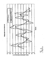
- FIG. 3 shows curves for a real breathing signal (point curve) and for an extrapolated respiratory signal (triangle curve).
- point curve a real breathing signal
- trimangle curve an extrapolated respiratory signal
- the present invention has recognized that additional information is available from the steps used, namely an actual real-time information about the position of the object.
- the object lies directly on the line of sight of the last X-ray projection used for the area stretching, exactly at the time of the x-ray image created thereby. It is possible to utilize this information to very accurately approximate the exact position of the object for the last time a projection line of sight is available, and for this, the shortest distance between the trajectory and the last line of sight becomes a perpendicular to the line of sight certainly. This lot is the so-called minimal transversal. At the point where the minimum transverse, i.
- the shortest (vertical) connection between the two named skewed lines, which meets the last projection line of sight, is once again a point, and this point in particular is very close to the real-time real position of the object, i. at the time the last X-ray line of sighting was created.
- the precision of the method will vary somewhat depending on the linearity of the object movement.
- a major axis of motion can be determined, which is typically a movement along the body longitudinal axis for implants in the lung, liver or kidney.
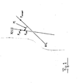
- FIG. 1 two X-ray sources are shown, which are provided with the reference numerals 1 and 2. Further, the figure shows an object O that moves at several consecutive times, that is, the object O [1] at time 1, the object O [2] at time 2, and the object O [3] at time 3
- the position tracking according to the invention is carried out as follows:
- a first X-ray image is created with the X-ray source 1, and a line of sight X [1, 1] in this X-ray image passes through the object O [1].
- the object then moves on and arrives at point 2 where it is represented by O [2].
- an X-ray image is again generated by the source 1, and the line of sight X [1, 2] is obtained.
- an X-ray with the X-ray source 2 and the line of sight X [2, 1 '] is created, ie at the intermediate time point 1'. If one now calculates or spans the area A1 between the line of sight X [1, 1] and X [1, 2], one can also calculate the point at which the object line of sight X [2, 1 '] from the X-ray source 2 at the intermediate time point 1 'the area A1 pierces and you get the point R1.
- This Intersection R1 may be considered as a first approximated reconstructed point on the object's path, but this information is only valid for a point in time in the past, since the object is already at O [2].
- the information about R1 can still be used if the present process is carried out again, ie at a time point 3, the line of sight X [1, 3] is again recorded with the X-ray tube 1, on which point O [3] at time 3 lies.
- the point R2 is determined at which the line of sight X [2, 2 '] pierces the surface A2 ( Area between X [1, 2] and X [1, 3])
- you already have two extrapolated points R1 and R2 and thus can determine an approximate trajectory for the object.
- This approximate trajectory is in FIG. 1 shown with R12; she is a straight line through R1 and R2.
- these processes can be repeated, and therefore is in the FIG. 1 also indicated the line of sight X [2, 3 '] on which then the point R3 would be.
- the process continues in this episode.
- FIG. 2 again shows the trajectory R12.
- the point P extrapol is shown once on the trajectory R12, which would result if only the position of the object at time 3 were calculated continuously on this trajectory.
- the actual calculation according to the invention takes a different route, processing the information that the actual object location P real must lie on the line of sight X [1, 3].
- the information about the position of this line of sight can be evaluated, namely by a minimum transverse M between the two skewed lines R12 and X [1, 3] is calculated.
- the minimum transverse is the shortest distance between the two straight lines in space, and it intersects the two straight lines vertically.
- the point P calc results , and this point P calc is very well approximated to the real position of the point P real .
- the point P calc is the very well approximated real-time position of the object O at time 3.
Description
Die Erfindung betrifft die nicht diagnostische, stereoskopische Röntgenverfolgung bewegter Objekte im Rahmen der Radiotherapie und Radiochirurgie. Speziell betrifft sie eine Röntgenverfolgung, bei der mit zwei Röntgenröhren wiederholt Röntgenbilder eines Objekts entlang zweier verschiedener, sich unter einem bekannten Winkel schneidender Sichtlinien durch das Zielgebiet eines Bestrahlungsgerätes aufgenommen werden.The invention relates to the non-diagnostic, stereoscopic X-ray tracking of moving objects in the context of radiotherapy and radiosurgery. Specifically, it relates to an X-ray trace in which X-ray images of an object are taken with two X-ray tubes repeatedly along two different lines of sight intersecting at a known angle through the target area of an irradiation device.
Eine Echtzeit-Röntgenverfolgung bewegter Ziele, beispielsweise implantierter Tracking-Marker, ist im Rahmen der Radiochirurgie bzw. Strahlentherapie grundsätzlich bekannt. So beschreibt beispielsweise die
Bei den hohen verwendeten Abtastraten, die notwendig sind, um die Bewegung genau zu verfolgen, wird der Patient bei solchen Systemen einer relativ hohen Strahlenbelastung ausgesetzt, wenn beide Röntgensysteme jeweils gleichzeitig aktiviert werden.With the high sampling rates needed to accurately track the motion, the patient is exposed to relatively high levels of radiation in such systems when both X-ray systems are activated simultaneously.
Es ist eine Aufgabe der vorliegenden Erfindung, eine stereoskopische Röntgenverfolgung für bewegte Objekte im Rahmen der Radiotherapie und Radiochirurgie zu schaffen, welche die Strahlenbelastung des Patienten reduziert.It is an object of the present invention to provide stereoscopic X-ray tracking for moving objects in the context of radiotherapy and radiosurgery, which reduces the radiation exposure of the patient.
Diese Aufgabe wird erfindungsgemäß durch ein nicht diagnostisches, stereoskopisches Röntgenverfolgungsverfahren gemäß dem Anspruch 1 sowie durch eine stereoskopische Röntgenverfolgungsvorrichtung gemäß dem Anspruch 9 gelöst. Die Unteransprüche definieren bevorzugte Ausführungsformen der Erfindung.This object is achieved by a non-diagnostic, stereoscopic X-ray tracking method according to
Die vorliegende Erfindung zeigt auf, wie ein bewegtes Objekt in einem Patienten verfolgt werden kann, also beispielsweise ein Objekt, das seine Lage mit der Atembewegung eines Patienten verändert. Wenn vor der Therapie mit bildgebenden Verfahren (CT, MR, etc.) dreidimensionale Bildaufnahmen des Patienten im Gebiet um das Behandlungsziel erstellt werden, auf denen auch das Objekt zu sehen ist, können diese bekannten Patientenstrukturen durch die erfindungsgemäße Echtzeit-Verfolgung des Objektes bzw. eines Markers oder einer Landmarke immer an ihrem gerade aktuellen Ort im dreidimensionalen Raum bestimmt werden. Es ist deshalb möglich, die Bestrahlung an die Bewegung des Objektes anzupassen (Bewegung des Patienten, Nachführen der Strahlvorrichtung, Gating = An- und Abschalten des Strahls zu geeigneten Zeitpunkten) und somit gesundes Gewebe zu schonen und krankes Gewebe gezielt zu bestrahlen.The present invention shows how a moving object in a patient can be tracked, such as an object that alters its position with the respiratory motion of a patient. If before the therapy with imaging methods (CT, MR, etc.) three-dimensional image recordings of the patient are created in the area around the treatment target on which the object can be seen, these known patient structures by the inventive real-time tracking of the object or of a marker or landmark always be determined at their current location in three-dimensional space. It is therefore possible to adapt the irradiation to the movement of the object (movement of the patient, tracking of the jet device, gating = switching the jet on and off at suitable times) and thus to preserve healthy tissue and to irradiate diseased tissue in a targeted manner.
Zu diesem Zweck beschreibt die vorliegende Erfindung ein nicht diagnostisches, stereoskopisches Röntgenverfolgungsverfahren zur Verfolgung bewegter Objekte im Rahmen der Radiotherapie und Radiochirurgie, bei dem mit zwei Röntgenröhren wiederholt Röntgenbilder eines Objekts entlang zweier verschiedener, sich unter einem bekannten Winkel schneidender Sichtlinien durch das Zielgebiet eines Bestrahlungsgerätes aufgenommen werden, dadurch gekennzeichnet, dass
- a) die Ansteuerung der Röntgenröhren so erfolgt, dass abwechselnd mit einer der beiden Röntgenröhren jeweils ein Bild erzeugt wird; und computerunterstützt
- b) eine Fläche bestimmt wird, die aufgespannt wird durch
- die Sichtlinie von einer ersten Röntgenröhre zum Objekt in einem zu einem früheren Zeitpunkt aufgenommenen Bild und
- die Sichtlinie von der ersten Röntgenröhre zu dem Objekt in einem zu einem späteren Zeitpunkt aufgenommenen Bild;
- c) ein Schnittpunkt bestimmt wird aus
- einer Sichtlinie von der zweiten Röntgenröhre zu dem Objekt in einem Bild, das zu einem Zeitpunkt aufgenommen wird, der zwischen dem früheren und dem späteren Zeitpunkt liegt, und
- der aufgespannten Fläche;
- d) eine weitere Fläche bestimmt wird, wobei der spätere Zeitpunkt zu einem neuen früheren Zeitpunkt wird, und wobei die weitere Fläche aufgespannt wird durch
- die Sichtlinie von der ersten Röntgenröhre zum Objekt in einem zu dem neuen früheren Zeitpunkt aufgenommenen Bild und
- die Sichtlinie von der ersten Röntgenröhre zu dem Objekt in einem zu einem neuen späteren Zeitpunkt aufgenommenen Bild;
- e) ein weiterer Schnittpunkt bestimmt wird aus
- einer Sichtlinie von der zweiten Röntgenröhre zu dem Objekt in einem Bild, das zu einem Zeitpunkt aufgenommen wird, der zwischen dem neuen früheren und dem neuen späteren Zeitpunkt liegt, und
- der weiteren aufgespannten Fläche
- f) die räumliche Verbindungsgerade R12, welche die Schnittpunkte verbindet, berechnet wird;
- g) die Minimaltransversale zwischen der Verbindungsgeraden R12 und der Sichtlinie des Objektes zum neuen späteren Zeitpunkt errechnet wird; und
- h) aus dem Schnittpunkt der Minimaltransversalen und der Sichtlinie zum neuen späteren Zeitpunkt die dreidimensionale Position des verfolgten Objektes approximiert wird.
- a) the control of the x-ray tubes is performed so that alternately with one of the two x-ray tubes, an image is generated; and computer-aided
- b) an area is determined which is spanned by
- the line of sight from a first x-ray tube to the object in a picture taken at an earlier time and
- the line of sight from the first x-ray tube to the object in an image taken at a later time;
- c) an intersection is determined
- a line of sight from the second X-ray tube to the object in an image taken at a time lying between the earlier and the later time, and
- the span surface;
- d) a further area is determined, the later time becomes a new earlier time, and wherein the further area is spanned by
- the line of sight from the first x-ray tube to the object in an image taken at the new earlier time and
- the line of sight from the first x-ray tube to the object in an image taken at a later later time;
- e) another intersection is determined
- a line of sight from the second x-ray tube to the object in an image taken at a time between the new earlier and the new later time, and
- the further stretched surface
- f) calculating the spatial connecting line R12 connecting the points of intersection;
- g) the minimum transverse between the connecting straight line R12 and the line of sight of the object is calculated at the new, later point in time; and
- h) the three-dimensional position of the tracked object is approximated from the intersection of the minimum transversal and the line of sight to the new later point in time.
Einfacher und allgemeiner ausgedrückt werden bei dem erfindungsgemäßen Verfahren mit zwei Röntgenröhren abwechselnd und wiederholt Röntgenbilder eines Objekts entlang zweier verschiedener Sichtlinien aufgenommen, und durch Flächen- und Schnittpunktsbestimmungen wird eine extrapolierte Objektbahn ermittelt. Die Minimaltraverse von der Objektbahn auf eine aktuelle Sichtlinie wird ermittelt und an ihrem Auftreffpunkt auf die Sichtlinie wird die dreidimensionale Position des verfolgten Objektes approximiert.More simply and more generally, in the method according to the invention with two x-ray tubes, x-ray images of an object are recorded alternately and repeatedly along two different lines of sight, and surface and intersection determinations are used to determine an extrapolated object trajectory. The minimum traverse from the object trajectory to a current line of sight is determined and displayed its impact point on the line of sight is approximated by the three-dimensional position of the tracked object.
Dieses Verfahren macht es also möglich, die Röntgenbilder in einem zeitlichen Abstand zu erfassen und mit Hilfe einer Approximation trotzdem sehr genau in Echtzeit die Lage des Objekts zu bestimmen, und zwar obwohl das Objekt sich während der Zeit zwischen zwei Röntgenvorgängen bewegen wird. Weil die Röntgenaufnahmen mit den beiden im System verwendeten Röntgenröhren abwechselnd erstellt werden, wird bei jedem Röntgen-"Schuss" nur eine Röhre aktiviert und die Strahlungsbelastung des Patienten kann um bis zu 50 % verringert werden, ohne die zeitliche Auflösung der Verfolgung, insbesondere entlang der Hauptbewegungsachse des Objektes, zu vermindern. Mit anderen Worten ersetzt die vorliegende Erfindung einen Hauptteil der zur Verfolgung notwendigen Röntgenaufnahmen durch eine geeignete und intelligente Verwendung von Bild- bzw. Lagedaten, die für das Objekt und die Röntgenaufnahmen (wegen im Raum bekanntet Sichtlinien) ohnehin vorhanden sind. Eine solche intelligente Datenverwertung bringt aber noch weitere Vorteile mit sich, wie sie im Folgenden erörtert werden.This method thus makes it possible to detect the X-ray images at a time interval and nevertheless to determine the position of the object very accurately in real time by means of an approximation, although the object will move during the time between two X-ray processes. Because the X-ray images are taken alternately with the two x-ray tubes used in the system, only one tube is activated at each x-ray "shot" and the patient's radiation exposure can be reduced by up to 50% without the temporal resolution of the tracking, especially along the Main axis of motion of the object, to diminish. In other words, the present invention replaces a major portion of the X-ray images necessary for tracing by suitably and intelligently using image data already present for the object and X-ray images (because of line-of-sight lines known in the room). However, such intelligent data exploitation brings with it further advantages, as will be discussed below.
Die Streustrahlung entlang einer der Bildaufnahmeachsen eines der Röntgensysteme beeinträchtigt die Bilderstellung des anderen Röntgensystems nicht, weil die beiden Systeme nicht zeitgleich aktiviert werden. Dies gilt insbesondere dann, wenn die Auslesezeiten an den jeweiligen Detektoren ebenfalls zeitversetzt sind. Der maximale Energieverbrauch des Gesamtsystems wird verringert, weil es nicht länger notwendig ist, beide Röntgenröhren gleichzeitig zu aktivieren. Die Gesamt-Nennleistung des Systems wird entsprechend reduziert. Die Erwärmung der Röntgenröhren, die für das Echtzeit-Tracking über längere Zeiträume eine funktionelle Einschränkung darstellt, wird verringert, wenn jede Röhre im Verhältnis zu herkömmlichen Systemen nur halb so oft betätigt wird. Falls notwendig, kann die zeitliche Auflösung des Verfolgungssystems bzw. Trackingsystems verdoppelt werden, und zwar indem jedes Röhren/Detektor-Paar mit seiner maximal möglichen Frequenz betätigt wird.The scattered radiation along one of the imaging axes of one of the X-ray systems does not affect the imaging of the other X-ray system because the two systems are not activated at the same time. This applies in particular if the readout times at the respective detectors are also time-delayed. The maximum energy consumption of the overall system is reduced because it is no longer necessary to simultaneously activate both x-ray tubes. The total rated power of the system is reduced accordingly. The heating of the X-ray tubes, which is a functional limitation for real-time tracking over extended periods of time, is reduced if each tube is actuated only half as often relative to conventional systems. If necessary, the temporal resolution of the tracking system can be doubled by operating each tube / detector pair at its maximum possible frequency.
Speziell der erstgenannte Vorteil, nämlich die Dosisreduktion für den Patienten, ist von hoher Wichtigkeit für Radiotherapie- bzw. Radiochirurgieanwendungen, bei denen die Verfolgung über lange Zeitabschnitte durchgeführt werden muss. Über die Zeit einer vollständigen Behandlung erreicht nämlich die Hautdosis, die durch die Tracking-Röntgenbestrahlung appliziert wird, oftmals kritische Niveaus.Especially the former advantage, namely the dose reduction for the patient, is of high importance for radiotherapy or radiosurgery applications where the Tracking over long periods of time must be performed. Indeed, over the period of complete treatment, the skin dose applied by the tracking X-ray often reaches critical levels.
Gemäß einer Ausführungsform der vorliegenden Erfindung wird der zeitliche Abstand zwischen dem Erzeugen eines Bildes mit der ersten und zweiten Röntgenröhre so eingestellt, dass in einem regelmäßigen Zeitabstand jeweils abwechselnd ein Bild mit der ersten und zweiten Röhre erzeugt wird. Das verfolgte Objekt kann ein Markierungsimplantat sein, insbesondere ein Implantat, das sich korreliert zur Atembewegung bewegt. Es kann aber auch eine röntgenabbildbare Körperstruktur oder Körperlandmarke sein, insbesondere eine Struktur oder Landmarke, die sich korreliert zur Atembewegung bewegt. Aus der Bewegung des Implantats bzw. der Struktur/Landmarke kann dann auf die Bewegung der umliegenden Körperstrukturen geschlossen werden, die als dreidimensionaler Datensatz (CT, MR etc.) in einem dem erfindungsgemäßen System angeschlossenen Navigationssystem hinterlegt sind, so dass auch der Echtzeit-Ort des tatsächlichen Bestrahlungsziels immer bekannt ist.According to an embodiment of the present invention, the time interval between the generation of an image with the first and second x-ray tubes is set such that an image is alternately formed with the first and second tubes at a regular time interval. The tracked object may be a marker implant, in particular an implant that moves in correlation with the respiratory motion. However, it can also be an X-ray-imageable body structure or body landmark, in particular a structure or landmark which moves in correlation to the respiratory movement. From the movement of the implant or the structure / landmark can then be concluded that the movement of the surrounding body structures, which are stored as a three-dimensional data set (CT, MR, etc.) in a navigation system connected to the system according to the invention, so that the real-time location the actual irradiation target is always known.
Die erfindungsgemäße Objektverfolgung arbeitet sehr genau, wenn die Minimaltransversale, also das kürzeste Lot von der Verbindungsgeraden auf die Sichtlinie, keine zu große Länge aufweist. Deshalb wird bei einer bevorzugten Ausführungsvariante die Länge der Minimaltransversalen mit einem vorgegebenen Schwellwert verglichen, wobei beim Überschreiten des Schwellwertes ein Zustand der Ungenauigkeit angenommen wird. Nunmehr kann einerseits eine Verfahrensanpassung vorgenommen werden, insbesondere eine Erhöhung der Abtastrate, die durch eine Verkleinerung der Zeitabstände zwischen den Bildern realisiert wird. Andererseits besteht auch die Möglichkeit, eine Fehlermeldung auszugeben, die den Verwender auf einen solchen Ungenauigkeitszustand hinweist.The object tracking according to the invention works very precisely when the minimum transverse, ie the shortest perpendicular from the connecting line to the line of sight, does not have too great a length. Therefore, in a preferred embodiment, the length of the minimum transversal is compared with a predetermined threshold value, wherein when the threshold value is exceeded, a state of inaccuracy is assumed. Now, on the one hand, a process adaptation can be carried out, in particular an increase of the sampling rate, which is realized by a reduction of the time intervals between the images. On the other hand, it is also possible to output an error message that indicates the user to such a state of inaccuracy.
Die Erfindung betrifft auch ein Programm, das, wenn es auf einem Computer läuft oder in einem Computer geladen ist, den Computer veranlasst, ein Verfahren durchzuführen, wie es hierin in verschiedenen Ausführungsformen beschrieben wird. Ferner betrifft sie ein Computerprogramm-Speichermedium, das ein solches Programm aufweist.The invention also relates to a program which, when run on a computer or loaded in a computer, causes the computer to perform a method as described herein in various embodiments. Further, it relates to a computer program storage medium having such a program.
Gemäß einem anderen Aspekt der vorliegenden Erfindung bezieht sich diese auf eine stereoskopische Röntgenverfolgungseinrichtung zur Verfolgung bewegter Objekte im Rahmen der Radiotherapie und Radiochirurgie, mit zwei Röntgenröhren (1, 2), die wiederholt Röntgenbilder eines Objekts (O) entlang zweier verschiedener, sich unter einem bekannten Winkel schneidender Sichtlinien durch das Zielgebiet eines Bestrahlungsgerätes aufnehmen, gekennzeichnet durch eine Steuerungseinrichtung, welche die Röntgenröhren (1, 2) abwechselnd aktiviert, um mit jeweils einer der beiden Röntgenröhren jeweils ein Bild zu erzeugen, sowie durch eine computerunterstützte Bildverarbeitungseinrichtung mit der
- eine Fläche bestimmt wird, die aufgespannt wird durch
- die Sichtlinie von einer ersten Röntgenröhre zum Objekt in einem zu einem früheren Zeitpunkt aufgenommenen Bild und
- die Sichtlinie von der ersten Röntgenröhre zu dem Objekt in einem zu einem späteren Zeitpunkt aufgenommenen Bild;
- ein Schnittpunkt bestimmt wird aus
- einer Sichtlinie von der zweiten Röntgenröhre zu dem Objekt in einem Bild, das zu einem Zeitpunkt aufgenommen wird, der zwischen dem früheren und dem späteren Zeitpunkt liegt, und
- der aufgespannten Fläche;
- eine weitere Fläche bestimmt wird, wobei der spätere Zeitpunkt zu einem neuen früheren Zeitpunkt wird, und wobei die weitere Fläche aufgespannt wird durch
- die Sichtlinie von der ersten Röntgenröhre zum Objekt in einem zu dem neuen früheren Zeitpunkt aufgenommenen Bild und
- die Sichtlinie von der ersten Röntgenröhre zu dem Objekt in einem zu einem neuen späteren Zeitpunkt aufgenommenen Bild;
- ein weiterer Schnittpunkt bestimmt wird aus
- einer Sichtlinie von der zweiten Röntgenröhre zu dem Objekt in einem Bild, das zu einem Zeitpunkt aufgenommen wird, der zwischen dem neuen früheren und dem neuen späteren Zeitpunkt liegt, und
- der weiteren aufgespannten Fläche;
- die räumliche Verbindungsgerade R12, welche die Schnittpunkte verbindet, berechnet wird; die Minimaltransversale zwischen der Verbindungsgeraden R12 und der Sichtlinie des Objektes zum neuen späteren Zeitpunkt errechnet wird; und
- aus dem Schnittpunkt der Minimaltransversalen und der Sichtlinie zum neuen späteren Zeitpunkt die dreidimensionale Position des verfolgten Objektes approximiert wird.
- a surface is determined, which is spanned by
- the line of sight from a first x-ray tube to the object in a picture taken at an earlier time and
- the line of sight from the first x-ray tube to the object in an image taken at a later time;
- an intersection is determined
- a line of sight from the second X-ray tube to the object in an image taken at a time lying between the earlier and the later time, and
- the span surface;
- a further surface is determined, wherein the later time is at a new earlier time, and wherein the further surface is spanned by
- the line of sight from the first x-ray tube to the object in an image taken at the new earlier time and
- the line of sight from the first x-ray tube to the object in an image taken at a later later time;
- another intersection is determined
- a line of sight from the second x-ray tube to the object in an image taken at a time between the new earlier and the new later time, and
- the further stretched surface;
- the spatial connecting line R12 connecting the intersections is calculated; the minimum transverse between the connecting line R12 and the line of sight of the object is calculated at the new later time; and
- the three-dimensional position of the tracked object is approximated from the intersection of the minimum transversal and the line of sight to the new later point in time.
Natürlich können alle hierin beschriebenen Merkmale, auch wenn sie verfahrensmäßig formuliert sind, durch entsprechende Vorrichtungen und Einrichtungen umgesetzt werden.Of course, all features described herein, even as formulated in procedural terms, may be implemented by appropriate devices and devices.
Mit etwas anderen Worten kann die vorliegende Erfindung auch so beschrieben werden, dass sie einen Weg aufzeigt, um dreidimensionale Koordinaten eines beweglichen Objektes trotz der Abweichungen von Echtzeit-Projektionslinien zu ermitteln. Durch das Errechnen der Oberfläche, die durch eine Projektionslinie des Objekts in einem Bild und durch ihre direkte Vorgängerin bestimmt wird, und durch die Berechnung des Schnittpunktes dieser Oberfläche mit einer Sichtlinie bzw. Projektionslinie desselben Objektes, erfasst von dem anderen Sichtwinkel, also durch die andere Röntgenröhre, zu einem Zeitpunkt zwischen den beiden vorgenannten Bilderfassungen, kann ein dreidimensionaler Punkt bestimmt werden. Dieser rekonstruierte dreidimensionale Punkt ist eine Annäherung der realen Position des Objektes zu diesem vorgegebenen Zeitpunkt. Die Genauigkeit dieser Rekonstruktion hängt von der Linearität der 3D-Bewegung des Objektes ab. Dieser rekonstruierte Punkt entspricht aber einem Zeitpunkt in der Vergangenheit und wegen dieses Zeitunterschiedes ist ein Echtzeit-Tracking somit noch nicht möglich.In other words, the present invention can also be described as providing a way to obtain three-dimensional coordinates of a moving object despite deviations from real-time projection lines. By computing the surface determined by a projection line of the object in an image and its direct predecessor, and by calculating the intersection of that surface with a line of sight or projection line of the same object detected from the other angle of view, that is the other X-ray tube, at a time between the two aforementioned image versions, a three-dimensional point can be determined. This reconstructed three-dimensional point is an approximation of the real position of the object at that given time. The accuracy of this reconstruction depends on the linearity of the 3D movement of the object. However, this reconstructed point corresponds to a point in time in the past and because of this time difference, real-time tracking is thus not yet possible.
Wenn aber die oben beschriebene Rekonstruktion eines 3D-Punktes in der Folge nochmals durchgeführt wird, erhält man zwei 3D-Punkte, die jeweils auf einer Projektionslinie einer Röntgeneinheit liegen.However, if the above-described reconstruction of a 3D point in the sequence is carried out again, two 3D points are obtained, each lying on a projection line of an X-ray unit.
Eine Linie durch diese beiden rekonstruierten Punkte würde die Bewegungsbahn des Objektes durch den dreidimensionalen Raum annähern. Ein Problem hierbei liegt darin, dass eine solche Bewegungsbahn, insbesondere bei nicht linearen bzw. über die Zeit veränderlichen Bewegungen eine ausreichend genaue Echtzeit-Ortsbestimmung für den Punkt oft nicht gestattet. Die
Kommt man nun zurück auf die durch zwei Punkte approximierte Bewegungsbahn des Objektes, so wird klar, dass eine solche approximierte Bahn alleine noch keine guten Ergebnisse bzw. Annäherung für ein Echtzeit-Tracking bieten kann.Returning now to the motion path of the object approximated by two points, it becomes clear that such an approximate path alone can not yet provide good results or approximation for real-time tracking.
Die vorliegende Erfindung hat aber erkannt, dass aus den angewendeten Schritten eine zusätzliche Information zur Verfügung steht, und zwar eine tatsächliche Echtzeit-Information über die Lage des Objektes. Das Objekt liegt nämlich direkt auf der Sichtlinie der letzten Röntgenprojektion, die für die Flächenaufspannung verwendet wird, und zwar genau zum Zeitpunkt des dabei erstellten Röntgenbildes. Man kann diese Information verwerten, um die exakte Position des Objektes für den letzten Zeitpunkt, an dem eine Projektions-Sichtlinie zur Verfügung steht, sehr genau anzunähern, und hierfür wird der kürzeste Abstand zwischen der Bewegungsbahn und der letzten Sichtlinie mit einem Lot auf die Sichtlinie bestimmt. Dieses Lot ist die so genannte Minimaltransversale. An der Stelle, wo die Minimaltransversale, d.h. die kürzeste (senkrechte) Verbindung zwischen den beiden genannten windschief zueinander liegenden Geraden, auf die letzte Projektions-Sichtlinie trifft, liegt wiederum ein Punkt, und gerade dieser Punkt liegt in sehr guter Annäherung an der realen Echtzeit-Position des Objektes, d.h. zu der Zeit, zu der die letzte Röntgensichtlinie zur Flächenaufspannung erstellt wurde.However, the present invention has recognized that additional information is available from the steps used, namely an actual real-time information about the position of the object. Namely, the object lies directly on the line of sight of the last X-ray projection used for the area stretching, exactly at the time of the x-ray image created thereby. It is possible to utilize this information to very accurately approximate the exact position of the object for the last time a projection line of sight is available, and for this, the shortest distance between the trajectory and the last line of sight becomes a perpendicular to the line of sight certainly. This lot is the so-called minimal transversal. At the point where the minimum transverse, i. the shortest (vertical) connection between the two named skewed lines, which meets the last projection line of sight, is once again a point, and this point in particular is very close to the real-time real position of the object, i. at the time the last X-ray line of sighting was created.
Die Präzision des Verfahrens wird abhängig von der Linearität der Objektbewegung etwas variieren. Speziell für bewegliche Objekte wie implantierte röntgensichtbare Marker, die herkömmlicherweise für ein Strahlungstherapie-Tracking verwendet werden, lässt sich eine Hauptbewegungsachse bestimmen, die typischerweise eine Bewegung entlang der Körperlängsachse für Implantate in der Lunge, in der Leber oder in den Nieren ist. In diesen Fällen ist es speziell von Wichtigkeit, eine gute räumliche/zeitliche Auflösung für das Objekt entlang dieser Richtung zu haben. Deshalb sollten bevorzugt die Sichtlinien beider Röntgeneinheiten (Röntgendetektoren) diese Hauptbewegungsachse unter einem ausreichend großen Winkel schneiden, so dass die Hauptbewegungskomponente gleich gut in Bildern beider Röntgenquellen/Detektoren-Paare erfasst werden kann.The precision of the method will vary somewhat depending on the linearity of the object movement. Especially for moving objects such as implanted radiopaque markers conventionally used for radiation therapy tracking, a major axis of motion can be determined, which is typically a movement along the body longitudinal axis for implants in the lung, liver or kidney. In these cases, it is especially important to have a good spatial / temporal resolution for the object along that direction. Therefore, the line of sight of both X-ray units (X-ray detectors) should preferably this main axis of motion under a Cut sufficiently large angle so that the main component of motion can be equally well captured in images of both X-ray source / detector pairs.
Die Erfindung wird im Weiteren anhand eines Ausführungsbeispiels und mit Hilfe der beiliegenden Zeichnungen näher erläutert. Sie kann alle hierin beschriebenen Merkmale einzeln sowie in jedweder sinnvollen Kombination umfassen. In den Zeichnungen zeigen:
Figur 1- eine schematische Darstellung der Punkt- und Flächenakquirierung für die erfindungsgemäße Röntgenverfolgung;
Figur 2- eine schematische Darstellung der Echtzeit-Objektortbestimmung mit Hilfe einer Minimaltransversalen; und
- Figur 3
- eine graphische Darstellung, die die Abweichung zwischen extrapolierter und realer Atemkurve zeigt.
- FIG. 1
- a schematic representation of the point and Flächenakquirierung for X-ray tracking according to the invention;
- FIG. 2
- a schematic representation of the real-time object location determination by means of a minimal transversal; and
- FIG. 3
- a graph showing the deviation between extrapolated and real breathing curve.
In der
Zum Zeitpunkt 1 wird mit der Röntgenquelle 1 ein erstes Röntgenbild erstellt, und eine Sichtlinie X[1, 1] in diesem Röntgenbild geht durch das Objekt O[1]. Das Objekt bewegt sich danach weiter und kommt zum Zeitpunkt 2 an die Stelle, an der es mit O[2] dargestellt ist. Auch zu diesem Zeitpunkt wird wiederum ein Röntgenbild durch die Quelle 1 erstellt, und man erhält die Sichtlinie X[1, 2].At
Zwischen den Zeitpunkten 1 und 2 (bei dieser Ausführungsform nach der Hälfte der vergangenen Zeit) wird eine Röntgenaufnahme mit der Röntgenquelle 2 und der Sichtlinie X[2, 1'] erstellt, also zu dem Zwischenzeitpunkt 1'. Wenn man nun zwischen den Sichtlinien X[1, 1] und X[1, 2] die Fläche A1 berechnet bzw. aufspannt, kann man auch den Punkt ausrechnen, an dem die Objekt-Sichtlinie X[2, 1'] von der Röntgenquelle 2 zum Zwischenzeitpunkt 1' die Fläche A1 durchstößt und man erhält den Punkt R1. Dieser Schnittpunkt R1 kann als ein erster angenähert rekonstruierter Punkt auf der Bahn des Objektes angesehen werden, aber diese Information ist nur für einen Zeitpunkt in der Vergangenheit gültig, da sich das Objekt sich inzwischen schon bei O[2] befindet.Between the
Die Information über R1 kann aber trotzdem verwendet werden, wenn der vorliegende Ablauf nochmals durchgeführt wird, d.h. zu einem Zeitpunkt 3 wird wiederum mit der Röntgenröhre 1 die Sichtlinie X[1, 3] aufgenommen, auf der der Punkt O[3] zum Zeitpunkt 3 liegt. Wenn nun wiederum ein Bild mit der Röntgenröhre 2 und der Sichtlinie X[2, 2'] für den Zwischenzeitpunkt 2' aufgenommen wird und wiederum der Punkt R2 bestimmt wird, an dem die Sichtlinie X[2, 2'] die Fläche A2 durchstößt (Fläche zwischen X[1, 2] und X[1, 3]), hat man schon zwei extrapolierte Punkte R1 und R2 und kann somit eine angenäherte Bewegungsbahn für das Objekt bestimmen. Diese angenäherte Bewegungsbahn ist in
Weil die lineare Annäherung der Bewegungsbahn R12 relativ mangelhaft sein kann, wie aus den Abweichungen in der realen und extrapolierten Atemkurve in
Die
Es lässt sich somit durch die erfindungsgemäße Objektverfolgung eine sehr gute Positionsannäherung bzw. Bestimmung für ein Objekt bei wesentlich reduzierter Strahlenbelastung und mit den anderen oben genannten Vorteilen realisieren.Thus, by means of the object tracking according to the invention, a very good position approximation or determination for an object can be realized with substantially reduced radiation exposure and with the other advantages mentioned above.
Claims (9)
- A non-diagnostic, stereoscopic x-ray tracking method for tracking moving objects in the context of radiotherapy and radiosurgery, in which two x-ray tubes (1, 2) are used to repeatedly record x-ray images of an object (O) along two different viewing lines through the target area of an irradiating apparatus, said viewing lines intersecting at a known angle, characterised in that:a) the x-ray tubes (1, 2) are controlled such that one image is generated in each case, alternately using one of the two x-ray tubes; and with the assistance of a computer:b) a surface (A1) is determined which is spanned by- the viewing line (X[1, 1]) from a first x-ray tube (1) to the object (O[1]) in an image recorded at an earlier point in time (t1) and- the viewing line (X[1, 2]) from the first x-ray tube (1) to the object (O[2]) in an image recorded at a later point in time (t2);c) an intersecting point (R1) is determined from- a viewing line from the second x-ray tube (2) to the object (O) in an image recorded at a point in time (t1') between the earlier point in time and the later point in time, and- the spanned surface (A1);d) another surface (A2) is determined, wherein the later point in time (t2) becomes a new earlier point in time (t2), and wherein said other surface is spanned by- the viewing line (X[1, 2]) from the first x-ray tube (1) to the object (O[2]) in an image recorded at the new earlier point in time (t2) and- the viewing line (X[1, 3]) from the first x-ray tube (1) to the object (O[3]) in an image recorded at a new later point in time (t3);e) another intersecting point (R2) is determined from- a viewing line from the second x-ray tube (2) to the object (O) in an image recorded at a point in time (t2') between the new earlier point in time and the new later point in time (t3), and- the other spanned surface (A2);f) the spatial straight connecting line (R12), which connects the intersecting points (R1 and R2), is calculated;g) the minimum transversal between the straight connecting line (R12) and the viewing line (X[1, 3]) of the object (O[3]) at the new later point in time (t3) is calculated; andh) the three-dimensional position (Pcalc) of the tracked object (O) is approximated from the intersecting point of the minimum transversal (M) and the viewing line (X[1, 3]) at the new later point in time (t3).
- The method according to claim 1, wherein the time interval between generating an image using the first and second x-ray tube (1, 2) is set such that one image is alternately generated using the first and second tube (1, 2), at regular time intervals (T) in each case.
- The method according to claim 1 or 2, wherein the tracked object is a marking implant, in particular an implant which moves in correlation with the movement of breathing.
- The method according to claim 1 or 2, wherein the tracked object is a body structure or body landmark which can be mapped using x-rays, in particular a structure or landmark which moves in correlation with the movement of breathing.
- The method according to any one of claims 1 to 4, wherein the length of the minimum transversal is compared with a predetermined threshold value, wherein if the threshold value is exceeded, a state of imprecision is assumed and the method is adapted, in particular by increasing the scanning rate, which is realised by reducing the time intervals between the images.
- The method according to any one of claims 1 to 4, wherein the length of the minimum transversal is compared with a predetermined threshold value, wherein if the threshold value is exceeded, a state of imprecision is assumed and an error message is outputted.
- A program which, when it is running on a computer, causes the computer to perform a method in accordance with any one of claims 1 to 6.
- A computer program storage medium comprising a program according to claim 7.
- A stereoscopic x-ray tracking device for tracking moving objects in the context of radiotherapy and radiosurgery, comprising two x-ray tubes (1, 2) which repeatedly record x-ray images of an object (O) along two different viewing lines through the target area of an irradiating apparatus, said viewing lines intersecting at a known angle, characterised by a control means which alternately activates the x-ray tubes (1, 2) in order to generate one image in each case, respectively using one of the two x-ray tubes, and characterised by a computer-assisted image processing means, using which:- a surface (A1) is determined which is spanned by- the viewing line (X[1, 1]) from a first x-ray tube (1) to the object (O[1]) in an image recorded at an earlier point in time (t1) and- the viewing line (X[1, 2]) from the first x-ray tube (1) to the object (O[2]) in an image recorded at a later point in time (t2);- an intersecting point (R1) is determined from- a viewing line from the second x-ray tube (2) to the object (O) in an image recorded at a point in time (t1') between the earlier point in time and the later point in time, and- the spanned surface (A1);- another surface (A2) is determined, wherein the later point in time (t2) becomes a new earlier point in time (t2), and wherein said other surface is spanned by- the viewing line (X[1, 2]) from the first x-ray tube (1) to the object (O[2]) in an image recorded at the new earlier point in time (t2) and- the viewing line (X[1, 3]) from the first x-ray tube (1) to the object (O[3]) in an image recorded at a new later point in time (t3);- another intersecting point (R2) is determined from- a viewing line from the second x-ray tube (2) to the object (O) in an image recorded at a point in time (t2') between the new earlier point in time and the new later point in time (t3), and- the other spanned surface (A2);- the spatial straight connecting line (R12), which connects the intersecting points (R1 and R2), is calculated;- the minimum transversal between the straight connecting line (R12) and the viewing line (X[1, 3]) of the object (O[1]) at the new later point in time (t3) is calculated; and- the three-dimensional position (Pcalc) of the tracked object (O) is approximated from the intersecting point of the minimum transversal (M) and the viewing line (X[1, 3]) at the new later point in time (t3).
Priority Applications (3)
| Application Number | Priority Date | Filing Date | Title |
|---|---|---|---|
| EP20060007103 EP1842487B1 (en) | 2006-04-04 | 2006-04-04 | Stereoscopic X-ray imaging of moving objects for radiotherapy and radiosurgery |
| DE200650004582 DE502006004582D1 (en) | 2006-04-04 | 2006-04-04 | Stereoscopic x-ray tracking of moving objects in the context of radiotherapy and radiosurgery |
| US11/696,200 US7400700B2 (en) | 2006-04-04 | 2007-04-04 | Non-diagnostic stereoscopic x-ray tracking of moving objects in the context of radiotherapy and radiosurgery, with time-offset image recording |
Applications Claiming Priority (1)
| Application Number | Priority Date | Filing Date | Title |
|---|---|---|---|
| EP20060007103 EP1842487B1 (en) | 2006-04-04 | 2006-04-04 | Stereoscopic X-ray imaging of moving objects for radiotherapy and radiosurgery |
Publications (2)
| Publication Number | Publication Date |
|---|---|
| EP1842487A1 EP1842487A1 (en) | 2007-10-10 |
| EP1842487B1 true EP1842487B1 (en) | 2009-08-19 |
Family
ID=36998574
Family Applications (1)
| Application Number | Title | Priority Date | Filing Date |
|---|---|---|---|
| EP20060007103 Active EP1842487B1 (en) | 2006-04-04 | 2006-04-04 | Stereoscopic X-ray imaging of moving objects for radiotherapy and radiosurgery |
Country Status (2)
| Country | Link |
|---|---|
| EP (1) | EP1842487B1 (en) |
| DE (1) | DE502006004582D1 (en) |
Family Cites Families (7)
| Publication number | Priority date | Publication date | Assignee | Title |
|---|---|---|---|---|
| US5207223A (en) | 1990-10-19 | 1993-05-04 | Accuray, Inc. | Apparatus for and method of performing stereotaxic surgery |
| DE50001418D1 (en) * | 2000-11-22 | 2003-04-10 | Brainlab Ag | Procedure for determining lung filling |
| EP1238684B1 (en) * | 2001-03-05 | 2004-03-17 | BrainLAB AG | Method for creating or updating a radiation treatment plan |
| US6914959B2 (en) * | 2001-08-09 | 2005-07-05 | Analogic Corporation | Combined radiation therapy and imaging system and method |
| DE60238842D1 (en) * | 2001-08-24 | 2011-02-17 | Mitsubishi Heavy Ind Ltd | RADIOLOGICAL TREATMENT DEVICE |
| DE10231630A1 (en) * | 2002-07-12 | 2004-01-29 | Brainlab Ag | System for patient positioning for radiotherapy / radiosurgery based on a stereoscopic x-ray system |
| DE50300447D1 (en) * | 2003-05-21 | 2005-05-19 | Prohealth Ag | Device for monitored tumor irradiation |
-
2006
- 2006-04-04 DE DE200650004582 patent/DE502006004582D1/en active Active
- 2006-04-04 EP EP20060007103 patent/EP1842487B1/en active Active
Also Published As
| Publication number | Publication date |
|---|---|
| DE502006004582D1 (en) | 2009-10-01 |
| EP1842487A1 (en) | 2007-10-10 |
Similar Documents
| Publication | Publication Date | Title |
|---|---|---|
| DE102007014715B4 (en) | Determination of control parameters for irradiation of a moving target volume in a body | |
| DE60011607T2 (en) | DEVICE AND METHOD FOR COMPENSATING THE BREATHING AND PATIENT MOVEMENT DURING TREATMENT | |
| EP1625876B1 (en) | Device for radiotherapy | |
| DE102008009765B4 (en) | Determining control parameters of an irradiation system for irradiation of a target volume | |
| EP2110161A1 (en) | Device for carrying out irradiation and method for monitoring same | |
| EP1380262A1 (en) | System for patient positioning for radiation therapy/radio surgery based on stereoscopic x-ray device | |
| DE10240727A1 (en) | Imaging system and method for optimizing an x-ray image | |
| DE102007014723A1 (en) | Planning target volume determination method for use in particle therapy system, involves determining target volume equivalent to minimum target volume in fictive homogeneous body, and extending equivalent target volume by a safety margin | |
| DE10033063A1 (en) | Respiration compensated radiation treatment tracks target volume using markers and switches beam | |
| DE19751761A1 (en) | System for continuous display of target location in medical treatments | |
| EP2189940A1 (en) | Calculation of indicator body elements and pre-indicator trajectories | |
| DE102008036478A1 (en) | Device and method for evaluating an activity distribution and irradiation system | |
| EP1894538A1 (en) | Method and device for determining the position of pelvic planes | |
| DE102008051476A1 (en) | Device and method for the determination of control parameters for an irradiation facility, irradiation facility and irradiation method | |
| DE102014210458B4 (en) | Determining a position of a target region of a patient to be irradiated in an irradiation device | |
| DE102010010192A1 (en) | Medical examination and / or treatment device | |
| DE102011083854B4 (en) | Time-resolved tomosynthesis imaging | |
| DE102009032429B4 (en) | Radiotherapy device with rotatable gantry | |
| EP2453983A1 (en) | Device and method for controlling an irradiation system | |
| DE10310127A1 (en) | Gating process, gating device and therapy facility | |
| EP1795230A1 (en) | Medical irradiation device | |
| EP1842487B1 (en) | Stereoscopic X-ray imaging of moving objects for radiotherapy and radiosurgery | |
| EP1388322A1 (en) | System for patient positioning in radiationtherapy / radiosurgery based on magnetic tracking of an implant | |
| DE102011081422B4 (en) | Image-based radiotherapy | |
| DE102011080607A1 (en) | X-ray apparatus has x-ray source pivotable around axis and detector co-operating with the x-ray source, where collimator is arranged between x-ray source and detector |
Legal Events
| Date | Code | Title | Description |
|---|---|---|---|
| PUAI | Public reference made under article 153(3) epc to a published international application that has entered the european phase |
Free format text: ORIGINAL CODE: 0009012 |
|
| 17P | Request for examination filed |
Effective date: 20060404 |
|
| AK | Designated contracting states |
Kind code of ref document: A1 Designated state(s): AT BE BG CH CY CZ DE DK EE ES FI FR GB GR HU IE IS IT LI LT LU LV MC NL PL PT RO SE SI SK TR |
|
| AX | Request for extension of the european patent |
Extension state: AL BA HR MK YU |
|
| AKX | Designation fees paid |
Designated state(s): DE FR GB IT |
|
| RAP1 | Party data changed (applicant data changed or rights of an application transferred) |
Owner name: BRAINLAB AG |
|
| GRAP | Despatch of communication of intention to grant a patent |
Free format text: ORIGINAL CODE: EPIDOSNIGR1 |
|
| RIN1 | Information on inventor provided before grant (corrected) |
Inventor name: ERBEL, STEPHAN |
|
| GRAS | Grant fee paid |
Free format text: ORIGINAL CODE: EPIDOSNIGR3 |
|
| GRAA | (expected) grant |
Free format text: ORIGINAL CODE: 0009210 |
|
| AK | Designated contracting states |
Kind code of ref document: B1 Designated state(s): DE FR GB IT |
|
| REG | Reference to a national code |
Ref country code: GB Ref legal event code: FG4D Free format text: NOT ENGLISH |
|
| REF | Corresponds to: |
Ref document number: 502006004582 Country of ref document: DE Date of ref document: 20091001 Kind code of ref document: P |
|
| PLBE | No opposition filed within time limit |
Free format text: ORIGINAL CODE: 0009261 |
|
| STAA | Information on the status of an ep patent application or granted ep patent |
Free format text: STATUS: NO OPPOSITION FILED WITHIN TIME LIMIT |
|
| 26N | No opposition filed |
Effective date: 20100520 |
|
| PG25 | Lapsed in a contracting state [announced via postgrant information from national office to epo] |
Ref country code: IT Free format text: LAPSE BECAUSE OF FAILURE TO SUBMIT A TRANSLATION OF THE DESCRIPTION OR TO PAY THE FEE WITHIN THE PRESCRIBED TIME-LIMIT Effective date: 20090819 |
|
| REG | Reference to a national code |
Ref country code: DE Ref legal event code: R082 Ref document number: 502006004582 Country of ref document: DE Representative=s name: SCHWABE SANDMAIR MARX, DE |
|
| REG | Reference to a national code |
Ref country code: DE Ref legal event code: R082 Ref document number: 502006004582 Country of ref document: DE Representative=s name: SCHWABE SANDMAIR MARX, DE Effective date: 20131104 Ref country code: DE Ref legal event code: R081 Ref document number: 502006004582 Country of ref document: DE Owner name: BRAINLAB AG, DE Free format text: FORMER OWNER: BRAINLAB AG, 85622 FELDKIRCHEN, DE Effective date: 20131104 Ref country code: DE Ref legal event code: R082 Ref document number: 502006004582 Country of ref document: DE Representative=s name: SCHWABE SANDMAIR MARX PATENTANWAELTE RECHTSANW, DE Effective date: 20131104 |
|
| REG | Reference to a national code |
Ref country code: FR Ref legal event code: PLFP Year of fee payment: 11 |
|
| REG | Reference to a national code |
Ref country code: DE Ref legal event code: R082 Ref document number: 502006004582 Country of ref document: DE Representative=s name: SSM SANDMAIR PATENTANWAELTE RECHTSANWALT PARTN, DE Ref country code: DE Ref legal event code: R082 Ref document number: 502006004582 Country of ref document: DE Representative=s name: SCHWABE SANDMAIR MARX PATENTANWAELTE RECHTSANW, DE Ref country code: DE Ref legal event code: R081 Ref document number: 502006004582 Country of ref document: DE Owner name: BRAINLAB AG, DE Free format text: FORMER OWNER: BRAINLAB AG, 85622 FELDKIRCHEN, DE |
|
| REG | Reference to a national code |
Ref country code: FR Ref legal event code: PLFP Year of fee payment: 12 |
|
| REG | Reference to a national code |
Ref country code: FR Ref legal event code: CA Effective date: 20170706 |
|
| REG | Reference to a national code |
Ref country code: FR Ref legal event code: PLFP Year of fee payment: 13 |
|
| P01 | Opt-out of the competence of the unified patent court (upc) registered |
Effective date: 20230508 |
|
| PGFP | Annual fee paid to national office [announced via postgrant information from national office to epo] |
Ref country code: FR Payment date: 20230420 Year of fee payment: 18 Ref country code: DE Payment date: 20230420 Year of fee payment: 18 |
|
| PGFP | Annual fee paid to national office [announced via postgrant information from national office to epo] |
Ref country code: GB Payment date: 20230419 Year of fee payment: 18 |