EP1841248A2 - Communication channel establishing method, communication system and communication apparatus - Google Patents
Communication channel establishing method, communication system and communication apparatus Download PDFInfo
- Publication number
- EP1841248A2 EP1841248A2 EP07251443A EP07251443A EP1841248A2 EP 1841248 A2 EP1841248 A2 EP 1841248A2 EP 07251443 A EP07251443 A EP 07251443A EP 07251443 A EP07251443 A EP 07251443A EP 1841248 A2 EP1841248 A2 EP 1841248A2
- Authority
- EP
- European Patent Office
- Prior art keywords
- communication
- base station
- power supply
- communication channel
- main power
- Prior art date
- Legal status (The legal status is an assumption and is not a legal conclusion. Google has not performed a legal analysis and makes no representation as to the accuracy of the status listed.)
- Withdrawn
Links
Images



Classifications
-
- H—ELECTRICITY
- H04—ELECTRIC COMMUNICATION TECHNIQUE
- H04W—WIRELESS COMMUNICATION NETWORKS
- H04W52/00—Power management, e.g. Transmission Power Control [TPC] or power classes
- H04W52/04—Transmission power control [TPC]
- H04W52/38—TPC being performed in particular situations
- H04W52/44—TPC being performed in particular situations in connection with interruption of transmission
-
- G—PHYSICS
- G06—COMPUTING OR CALCULATING; COUNTING
- G06Q—INFORMATION AND COMMUNICATION TECHNOLOGY [ICT] SPECIALLY ADAPTED FOR ADMINISTRATIVE, COMMERCIAL, FINANCIAL, MANAGERIAL OR SUPERVISORY PURPOSES; SYSTEMS OR METHODS SPECIALLY ADAPTED FOR ADMINISTRATIVE, COMMERCIAL, FINANCIAL, MANAGERIAL OR SUPERVISORY PURPOSES, NOT OTHERWISE PROVIDED FOR
- G06Q10/00—Administration; Management
- G06Q10/08—Logistics, e.g. warehousing, loading or distribution; Inventory or stock management
- G06Q10/087—Inventory or stock management, e.g. order filling, procurement or balancing against orders
-
- H—ELECTRICITY
- H04—ELECTRIC COMMUNICATION TECHNIQUE
- H04W—WIRELESS COMMUNICATION NETWORKS
- H04W24/00—Supervisory, monitoring or testing arrangements
- H04W24/04—Arrangements for maintaining operational condition
-
- H—ELECTRICITY
- H04—ELECTRIC COMMUNICATION TECHNIQUE
- H04W—WIRELESS COMMUNICATION NETWORKS
- H04W52/00—Power management, e.g. Transmission Power Control [TPC] or power classes
- H04W52/02—Power saving arrangements
- H04W52/0209—Power saving arrangements in terminal devices
- H04W52/0225—Power saving arrangements in terminal devices using monitoring of external events, e.g. the presence of a signal
- H04W52/0229—Power saving arrangements in terminal devices using monitoring of external events, e.g. the presence of a signal where the received signal is a wanted signal
- H04W52/0235—Power saving arrangements in terminal devices using monitoring of external events, e.g. the presence of a signal where the received signal is a wanted signal where the received signal is a power saving command
-
- H—ELECTRICITY
- H04—ELECTRIC COMMUNICATION TECHNIQUE
- H04W—WIRELESS COMMUNICATION NETWORKS
- H04W52/00—Power management, e.g. Transmission Power Control [TPC] or power classes
- H04W52/04—Transmission power control [TPC]
- H04W52/06—TPC algorithms
- H04W52/08—Closed loop power control
-
- Y—GENERAL TAGGING OF NEW TECHNOLOGICAL DEVELOPMENTS; GENERAL TAGGING OF CROSS-SECTIONAL TECHNOLOGIES SPANNING OVER SEVERAL SECTIONS OF THE IPC; TECHNICAL SUBJECTS COVERED BY FORMER USPC CROSS-REFERENCE ART COLLECTIONS [XRACs] AND DIGESTS
- Y02—TECHNOLOGIES OR APPLICATIONS FOR MITIGATION OR ADAPTATION AGAINST CLIMATE CHANGE
- Y02D—CLIMATE CHANGE MITIGATION TECHNOLOGIES IN INFORMATION AND COMMUNICATION TECHNOLOGIES [ICT], I.E. INFORMATION AND COMMUNICATION TECHNOLOGIES AIMING AT THE REDUCTION OF THEIR OWN ENERGY USE
- Y02D30/00—Reducing energy consumption in communication networks
- Y02D30/70—Reducing energy consumption in communication networks in wireless communication networks
Definitions
- the present invention relates to a communication channel establishing method that involves searching beacons transmitted from a base station, receiving a beacon according to the search result, and establishing a communication channel with the base station based on the received beacon; a communication system using such a method; and a communication apparatus.
- electronic inventory tags having rewritable display information are registered in a host computer to then be placed on product shelves, and the host computer may access the electronic inventory tags via an access point to rewrite the display information of the electronic inventory tags at the host computer side (e.g. see Japanese Laid-Open Patent Publications No. 2002-304673 , No. 2005-99888 , No. 2002-109177 , No. 2004-265196 , and No. 9-138892 ).
- a communication system determines a communication channel for establishing communication between an electronic inventory tag and an access point using a beacon, In the case where the communication system using a beacon is implemented, an electronic inventory tag scans all available communication channels to determine the communication channel to be established with an access point.
- the node has to search all communication channels to reestablish the communication channel with the coordinator.
- the coordinator is unable to establish communication due to power failure, for example, the node may keep on searching all communication channels even though a communication counterpart cannot be accessed and power may needlessly be consumed.
- the coordinator recovers from power failure, a long recovery time may be needed to reestablish the communication channel since the node has to search all communication channels.
- the electronic tags corresponding to nodes are driven by batteries, and therefore, measures for reducing the power consumption of the electronic inventory tags are in demand.
- a communication establishing method, a communication system, and a communication apparatus are provided for reducing power consumption and enabling high speed communication recovery.
- a communication channel establishing method is provided that is used in a communication system including a base station that transmits a beacon on a predetermined communication channel and a communication apparatus that receives the beacon from the base station and establishes communication with the base station using the predetermined communication channel, the method including the steps of:
- the communication apparatus may store current status information upon receiving the main power supply shutoff notification signal from the base station.
- the communication apparatus may intermittently perform communication channel search after receiving the main power supply shutoff notification signal from the base station.
- the base station may transmit a main power supply recovery notification signal to the communication apparatus when the main power supply is turned on after being shut off; and the communication apparatus may receive the main power supply recovery notification signal from the base station and reestablish communication with the base station using the stored current communication channel.
- a communication system that includes:
- a communication apparatus that receives a beacon from a base station and establishes communication using a communication channel according to the received beacon, the apparatus including:
- FIG. 1 is a block diagram showing a configuration of an electronic inventory tag system according to an embodiment of the present invention.
- the electronic inventory tag system 100 includes a manager apparatus 111, relay apparatuses 112, and electronic inventory tags 113.
- the electronic inventory tag system 100 manages the electronic inventory tags 113 placed on product shelves using the relay apparatuses 112 that relay communication between the electronic inventory tags 113 and the manager apparatus.111.
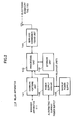
- FIG. 2 is a block diagram showing a configuration of the relay apparatus 112.
- the relay apparatus 112 includes a communications unit 141, a processing unit 142, a storage unit 143, a wireles's communications unit 144, a power supply circuit 145, and a backup power supply 146.
- the communications unit 141 is connected to the manager apparatus 111 via a network such as a LAN, a WAN, or a dedicated line to establish communication with the manager apparatus 111.
- a network such as a LAN, a WAN, or a dedicated line to establish communication with the manager apparatus 111.
- the processing unit 142 may include a microcomputer, for example, and performs processes such as relaying communications between the manager apparatus 111 and the electronic inventory tags 113 based on programs installed in the storage unit 143.
- the storage unit 143 may include a ROM, a RAM, and a rewritable nonvolatile memory such as an EEPROM, for example, to store communication control programs and communicable electronic inventory tag information.
- the wireless communications unit 144 establishes wireless communication with the electronic inventory tags 113.
- the power supply circuit 145 is connected to an external alternating current power supply such as a commercial power supply, converts the alternating current into a direct current voltage, and supplies the direct current voltage as a drive voltage to the communications unit 141, the processing unit 142, the storage unit 143, and the wireless communications unit 144.
- an external alternating current power supply such as a commercial power supply
- converts the alternating current into a direct current voltage and supplies the direct current voltage as a drive voltage to the communications unit 141, the processing unit 142, the storage unit 143, and the wireless communications unit 144.
- the power supply circuit 145 transmits a signal to the processing unit 142 indicating that the main power supply has been shut off
- the power supply circuit 145 transmits a signal to the processing unit 142 indicating that the main power supply has been turned on.
- the backup power supply 146 is a rechargeable battery such as a Ni-Cd battery, a lithium ion battery, or an electric dual layer capacitor that is charged by the direct current voltage generated by the power supply circuit 145.
- the backup power supply 146 supplies drive power to the communications unit 141, the processing unit 142, the storage unit 143, and the wireless communications unit 144 for a predetermined period of time so that termination programs may be properly executed when the alternating current power supply is shut off.
- FIG. 3 is a block diagram showing a configuration of the electronic inventory tag 113.
- the electronic inventory tag 113 includes a wireless communications unit 151, a processing unit 152, a storage unit 153, a display unit 154, and a battery 155.
- the wireless communications unit 151 establishes communication with the relay apparatus 112. It is noted that communication channel control of the wireless communications unit 151 may be performed based on instructions from the processing unit 152.
- the processing unit 152 may include a CPU, for example, and is configured to control communications with the relay apparatus 112 and display operations of the display unit 154 based on programs stored in the storage unit 153.
- the storage unit 153 may include a rewritable nonvolatile storage device such as an EEPROM that stores programs to be executed by the processing unit 152 as well as inventory tag ID and product code. A part of the inventory tag ID and the product code may be registered beforehand and changed by the relay apparatus 112.
- the display unit 154 may include a LCD, an EL panel, or electronic paper, for example, and is configured to display information such as product name, product code, and price according to instructions from the processing unit 152.
- the battery 155 is a miniature battery that supplies drive power to the wireless communications unit 151, the processing unit 152, the storage unit 153, and the display unit 154.
- FIG. 4 is a diagram illustrating a transmission pattern of beacons transmitted from the relay apparatus 112.
- the relay apparatus 112 periodically transmits a beacon group B including plural beacons b at beacon transmission cycles of Tbcn_cycl milliseconds.
- Tbn_intrvl the transmission time period for transmitting the beacon group B
- Tbn_intrvl the transmission time period for transmitting the beacon group B
- the transmission time period Tbcn for transmitting each beacon b is set to the time required for the electronic inventory tag 113 to receive the beacon b.
- the relay apparatus 112 may transmit a beacon b to the electronic inventory tag 113 every two seconds, for example, to inform the electronic inventory tag apparatus 113 of the current communication status. It is noted that the time period between two beacon transmissions is referred to as frame.
- a frame corresponds to a basic communication unit for communication between the relay apparatus 112 and the electronic inventory tag 113.
- a beacon includes call information such as an identification number of the electronic inventory tag 113 with which communication is to be established in the frame following this beacon.
- a frame may be subdivided into sixteen periods, for example, and each of the subdivided periods (125 millisecond periods) is referred to as a data slot.
- a time period for transmitting a beacon is assigned at the head of a frame.
- the head of the first data slot of a frame corresponds to a time period for transmitting a beacon.
- the second to fifteenth data slots of the frame may also have similar configurations. However, the type of data to be transmitted in the second to fifteenth data slots is different from that transmitted in the first data slot. Specifically, a message referred to as null beacon, which has a function different from that of a beacon, is transmitted at the head of each of the second to fifteenth data slots.
- null beacon which has a function different from that of a beacon
- the relay apparatus 112 may transmit a beacon every two seconds, and transmit a null beacon every 125 milliseconds after transmission of a beacon. The transmission of the null beacon at 125-millisecond intervals may continue until a next beacon is transmitted.
- periods for transmitting a beacon once and a null beacon fifteen times are included in one frame. It is noted that a beacon and a null beacon have different functions as is described below.
- a beacon has a function for calling the electronic inventory tag 113 and contains call information such as the identification number of the relevant electronic inventory tag 113.
- a null beacon is used when the electronic inventory tag 113 conducts channel search for accessing the relay apparatus 112.
- the electronic inventory tag 113 does not use the null beacon for purposes other than channel search.
- the null beacon may include a temporal offset value with respect to the beacon transmission period. In this way, the timing of the beacon transmission period may be determined when at least one null beacon is obtained, for example.
- FIG. 5 is a flowchart illustrating operations of the relay apparatus 112.
- the processing unit 142 of the relay apparatus 112 Upon receiving a notification signal from the power supply circuit 145 indicating that the alternating current power supply corresponding to the main power supply has been shut off (step S1-1), the processing unit 142 of the relay apparatus 112 generates a power failure notification signal (main power shutoff notification signal) and transmits the generated signal to the electronic inventory tag 113 via the wireless communications unit 144 (step S1-2).
- the processing unit 142 stores the communication channel established at the time the power failure notification signal is generated in the storage unit 143 (step S1-3), and stops beacon transmission (step S1-4).
- the processing unit 142 Upon determining based on a notification signal transmitted from the power supply circuit 145 that the alternating current power supply corresponding to the main power supply has been turned on again, the processing unit 142 reads the communication channel stored in the storage unit 143 (step S1-6), starts beacon transmission using the read communication channel (step S1-7), and transmits a power failure recovery notification signal (power failure recovery notification signal) to the electronic inventory tag 113 (step S1-8).
- the relay apparatus 112 may restore communication with the electronic inventory tag 113 to the communication status right before the shutoff of the main power supply and communication with the electronic inventory tag 113 may be established using the same communication channel used before the shutoff of the main power supply.
- processing unit 142 may resume normal communication operations (step S1-9).
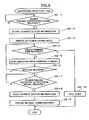
- FIG. 6 is a flowchart illustrating operations of the electronic inventory tag 113.
- the processing unit 152 of the electronic inventory tag 113 Upon receiving a power failure notification signal from the relay apparatus 112 (step S2-1), the processing unit 152 of the electronic inventory tag 113 stores current status information including the current communication channel in the storage unit 153 (step S2-2), and switches to power saving mode in which communication channel search is performed intermittently(step S2-3),
- the processing unit 152 of the electronic inventory tag 113 scans beacons transmitted from the relay apparatus 112 using the current communication channel stored in the storage unit 153 (step S2-5). Then, upon receiving a beacon as a result of scanning the beacons using the current communication channel (step S2-6) and receiving a power failure recovery notification signal from the relay apparatus 112 (step S2-7), the processing unit 152 reads the current status information such as identification number and product code stored in the storage unit 153 (step S2-8), and resumes normal communication with the relay apparatus 112 (step S2-9).
- step S2-4 upon determining that the predetermined time has already elapsed in step S2-4, the processing unit 152 of the electronic inventory tag 113 presumes that it has moved to a communication area of a different relay apparatus 112 and switches to full scan mode for searching all communication channels (step S2-10).
- the electronic inventory tag 113 when the main power supply of the relay apparatus 112 is shut off due to power failure, for example, the electronic inventory tag 113 is notified of the power failure by the relay apparatus 112 and the communication channel established at the time of the notification is stored before the electronic inventory tag 113 switches to power saving mode.
- the electronic inventory tag 113 may not have to scan all communication channels upon reestablishing communication with the relay apparatus 112 to thereby limit unnecessary channel scanning and reduce power consumption of the electronic inventory tag 113.
- the electronic inventory tag 113 may reestablish communication with the relay apparatus 112 using the stored communication channel so that high speed recovery may be possible.
- communication between a relay apparatus 112 and an electronic inventory tag 113 of an electronic inventory tag system 100 is illustrated as an exemplary embodiment of the present invention, However, the present invention is not limited to such an embodiment, and may be applied to any communication system having a base station that transmits a beacon on a predetermined communication channel and a communication apparatus that receives the beacon from the base station and establishes communication using the predetermined communication channel.
Landscapes
- Engineering & Computer Science (AREA)
- Computer Networks & Wireless Communication (AREA)
- Signal Processing (AREA)
- Business, Economics & Management (AREA)
- Economics (AREA)
- Marketing (AREA)
- Quality & Reliability (AREA)
- Finance (AREA)
- Entrepreneurship & Innovation (AREA)
- Human Resources & Organizations (AREA)
- Accounting & Taxation (AREA)
- Operations Research (AREA)
- Development Economics (AREA)
- Strategic Management (AREA)
- Tourism & Hospitality (AREA)
- Physics & Mathematics (AREA)
- General Business, Economics & Management (AREA)
- General Physics & Mathematics (AREA)
- Theoretical Computer Science (AREA)
- Mobile Radio Communication Systems (AREA)
- Small-Scale Networks (AREA)
Abstract
Description
- The present invention relates to a communication channel establishing method that involves searching beacons transmitted from a base station, receiving a beacon according to the search result, and establishing a communication channel with the base station based on the received beacon; a communication system using such a method; and a communication apparatus.
- In an electronic inventory tag system, electronic inventory tags having rewritable display information are registered in a host computer to then be placed on product shelves, and the host computer may access the electronic inventory tags via an access point to rewrite the display information of the electronic inventory tags at the host computer side (e.g. see
Japanese Laid-Open Patent Publications No. 2002-304673 No. 2005-99888 No. 2002-109177 No. 2004-265196 No. 9-138892 - In such an electronic inventory tag system, a communication system is used that determines a communication channel for establishing communication between an electronic inventory tag and an access point using a beacon, In the case where the communication system using a beacon is implemented, an electronic inventory tag scans all available communication channels to determine the communication channel to be established with an access point.
- However, according to such a communication method, once communication between a coordinator and a node is shut off, the node has to search all communication channels to reestablish the communication channel with the coordinator. In this case, when the coordinator is unable to establish communication due to power failure, for example, the node may keep on searching all communication channels even though a communication counterpart cannot be accessed and power may needlessly be consumed. Also, even when the coordinator recovers from power failure, a long recovery time may be needed to reestablish the communication channel since the node has to search all communication channels.
- It is noted that in the electronic inventory tag system, the electronic tags corresponding to nodes are driven by batteries, and therefore, measures for reducing the power consumption of the electronic inventory tags are in demand.
- According to one aspect of the present invention, a communication establishing method, a communication system, and a communication apparatus are provided for reducing power consumption and enabling high speed communication recovery.
- According to an embodiment of the present invention, a communication channel establishing method is provided that is used in a communication system including a base station that transmits a beacon on a predetermined communication channel and a communication apparatus that receives the beacon from the base station and establishes communication with the base station using the predetermined communication channel, the method including the steps of:
- detecting at the base station whether a main power supply has been shut off;
- driving the base station by a backup power supply and transmitting a power supply shutoff notification signal from the base station to the communication apparatus upon detecting that the main power supply has been shut off;
- storing a current communication channel of the communication apparatus when the power supply shutoff notification signal from the base station is received by the communication unit; and
- reestablishing communication with the base station at the communication apparatus using the stored current communication channel upon recovery of the main power supply,
- In one preferred embodiment of the present invention, the communication apparatus may store current status information upon receiving the main power supply shutoff notification signal from the base station.
- In another preferred embodiment of the present invention, the communication apparatus may intermittently perform communication channel search after receiving the main power supply shutoff notification signal from the base station.
- In another preferred embodiment of the present invention, the base station may transmit a main power supply recovery notification signal to the communication apparatus when the main power supply is turned on after being shut off; and
the communication apparatus may receive the main power supply recovery notification signal from the base station and reestablish communication with the base station using the stored current communication channel. - According to another embodiment of the present invention, a communication system is provided that includes:
- a base station that transmits a beacon on a predetermined communication channel; and
- a communication apparatus that receives the beacon from the base station and establishes communication with the base station using the predetermined communication channel; wherein
- the base station detects whether a main power supply has been shut off, receives drive power from a backup power supply when the main power supply is shut off, and transmits a main power shutoff notification signal to the communication apparatus; and
- the communication apparatus stores a current communication channel upon receiving the main power shutoff notification signal from the base station, and reestablishes communication with the base station using the stored current communication channel upon recovery of the main power supply.
- According to another embodiment of the present invention, a communication apparatus is provided that receives a beacon from a base station and establishes communication using a communication channel according to the received beacon, the apparatus including:
- a communications unit that establishes communication with the base station; and
- a control unit that stores a current communication channel upon receiving a main power supply shutoff notification signal from the base station via the communications unit, and searches subsequent beacons transmitted from the base station using the stored current communication channel.
-
- FIG. 1 is a block diagram illustrating a configuration of an electronic inventory tag system according to an embodiment of the present invention;
- FIG. 2 is a block diagram showing a configuration of a relay apparatus;
- FIG. 3 is a block diagram showing configuration of an electronic inventory tag;
- FIG. 4 is a diagram illustrating a transmission pattern of beacons transmitted from the relay apparatus;
- FIG. 5 is a flowchart illustrating operations of the relay apparatus; and
- FIG. 6 is a flowchart illustrating operations of the electronic inventory tag.
- In the following, preferred embodiments of the present invention are described with reference to the accompanying drawings.
- FIG. 1 is a block diagram showing a configuration of an electronic inventory tag system according to an embodiment of the present invention.
- The electronic
inventory tag system 100 according to the present embodiment includes amanager apparatus 111,relay apparatuses 112, andelectronic inventory tags 113. The electronicinventory tag system 100 manages theelectronic inventory tags 113 placed on product shelves using therelay apparatuses 112 that relay communication between theelectronic inventory tags 113 and the manager apparatus.111. - FIG. 2 is a block diagram showing a configuration of the
relay apparatus 112. - The
relay apparatus 112 includes acommunications unit 141, aprocessing unit 142, astorage unit 143, a wireles'scommunications unit 144, apower supply circuit 145, and abackup power supply 146. - The
communications unit 141 is connected to themanager apparatus 111 via a network such as a LAN, a WAN, or a dedicated line to establish communication with themanager apparatus 111. - The
processing unit 142 may include a microcomputer, for example, and performs processes such as relaying communications between themanager apparatus 111 and theelectronic inventory tags 113 based on programs installed in thestorage unit 143. - The
storage unit 143 may include a ROM, a RAM, and a rewritable nonvolatile memory such as an EEPROM, for example, to store communication control programs and communicable electronic inventory tag information. - The
wireless communications unit 144 establishes wireless communication with theelectronic inventory tags 113. - The
power supply circuit 145 is connected to an external alternating current power supply such as a commercial power supply, converts the alternating current into a direct current voltage, and supplies the direct current voltage as a drive voltage to thecommunications unit 141, theprocessing unit 142, thestorage unit 143, and thewireless communications unit 144. When the alternating current power supply corresponding to a main power supply is shut off, thepower supply circuit 145 transmits a signal to theprocessing unit 142 indicating that the main power supply has been shut off, and when the alternating current power supply corresponding to the main power supply is turned on, thepower supply circuit 145 transmits a signal to theprocessing unit 142 indicating that the main power supply has been turned on. - The
backup power supply 146 is a rechargeable battery such as a Ni-Cd battery, a lithium ion battery, or an electric dual layer capacitor that is charged by the direct current voltage generated by thepower supply circuit 145. Thebackup power supply 146 supplies drive power to thecommunications unit 141, theprocessing unit 142, thestorage unit 143, and thewireless communications unit 144 for a predetermined period of time so that termination programs may be properly executed when the alternating current power supply is shut off. - FIG. 3 is a block diagram showing a configuration of the
electronic inventory tag 113. - The
electronic inventory tag 113 includes awireless communications unit 151, aprocessing unit 152, astorage unit 153, adisplay unit 154, and abattery 155. - The
wireless communications unit 151 establishes communication with therelay apparatus 112. It is noted that communication channel control of thewireless communications unit 151 may be performed based on instructions from theprocessing unit 152. - The
processing unit 152 may include a CPU, for example, and is configured to control communications with therelay apparatus 112 and display operations of thedisplay unit 154 based on programs stored in thestorage unit 153. - The
storage unit 153 may include a rewritable nonvolatile storage device such as an EEPROM that stores programs to be executed by theprocessing unit 152 as well as inventory tag ID and product code. A part of the inventory tag ID and the product code may be registered beforehand and changed by therelay apparatus 112. - The
display unit 154 may include a LCD, an EL panel, or electronic paper, for example, and is configured to display information such as product name, product code, and price according to instructions from theprocessing unit 152. - The
battery 155 is a miniature battery that supplies drive power to thewireless communications unit 151, theprocessing unit 152, thestorage unit 153, and thedisplay unit 154. - In the following, communication data that are exchanged between the
relay apparatus 112 and theelectronic inventory tag 113 are described. - FIG. 4 is a diagram illustrating a transmission pattern of beacons transmitted from the
relay apparatus 112. - The
relay apparatus 112 periodically transmits a beacon group B including plural beacons b at beacon transmission cycles of Tbcn_cycl milliseconds. Provided that the transmission time period for transmitting the beacon group B is denoted as Tbn_intrvl milliseconds, the relationship between the beacon transmission cycle Tbcn_cycl and the beacon group transmission time period Tbn_intrvl may expressed as follows:
- Also, provided that the number of beacons b included in the bacon group B is denoted as N and the transmission time period for transmitting each beacon b is denoted as Tbcn milliseconds, the beacon group transmission time period Tbcn_intrvl may be expressed as follows:

- In the present embodiment, the transmission time period Tbcn for transmitting each beacon b is set to the time required for the
electronic inventory tag 113 to receive the beacon b. - The
relay apparatus 112 may transmit a beacon b to theelectronic inventory tag 113 every two seconds, for example, to inform the electronicinventory tag apparatus 113 of the current communication status. It is noted that the time period between two beacon transmissions is referred to as frame. A frame corresponds to a basic communication unit for communication between therelay apparatus 112 and theelectronic inventory tag 113. A beacon includes call information such as an identification number of theelectronic inventory tag 113 with which communication is to be established in the frame following this beacon. - A frame may be subdivided into sixteen periods, for example, and each of the subdivided periods (125 millisecond periods) is referred to as a data slot.
- A time period for transmitting a beacon is assigned at the head of a frame. Thus, the head of the first data slot of a frame corresponds to a time period for transmitting a beacon.
- The second to fifteenth data slots of the frame may also have similar configurations. However, the type of data to be transmitted in the second to fifteenth data slots is different from that transmitted in the first data slot. Specifically, a message referred to as null beacon, which has a function different from that of a beacon, is transmitted at the head of each of the second to fifteenth data slots.
- In one embodiment, the
relay apparatus 112 may transmit a beacon every two seconds, and transmit a null beacon every 125 milliseconds after transmission of a beacon. The transmission of the null beacon at 125-millisecond intervals may continue until a next beacon is transmitted. - In this case, periods for transmitting a beacon once and a null beacon fifteen times are included in one frame. It is noted that a beacon and a null beacon have different functions as is described below.
- Normally, a beacon has a function for calling the
electronic inventory tag 113 and contains call information such as the identification number of the relevantelectronic inventory tag 113. - On the other hand, a null beacon is used when the
electronic inventory tag 113 conducts channel search for accessing therelay apparatus 112. In the present embodiment, theelectronic inventory tag 113 does not use the null beacon for purposes other than channel search. - The null beacon may include a temporal offset value with respect to the beacon transmission period. In this way, the timing of the beacon transmission period may be determined when at least one null beacon is obtained, for example.
- In the following, operations of the communication system according to an embodiment of the present invention are described.
- FIG. 5 is a flowchart illustrating operations of the
relay apparatus 112. - Upon receiving a notification signal from the
power supply circuit 145 indicating that the alternating current power supply corresponding to the main power supply has been shut off (step S1-1), theprocessing unit 142 of therelay apparatus 112 generates a power failure notification signal (main power shutoff notification signal) and transmits the generated signal to theelectronic inventory tag 113 via the wireless communications unit 144 (step S1-2). - Also, the
processing unit 142 stores the communication channel established at the time the power failure notification signal is generated in the storage unit 143 (step S1-3), and stops beacon transmission (step S1-4). - Upon determining based on a notification signal transmitted from the
power supply circuit 145 that the alternating current power supply corresponding to the main power supply has been turned on again, theprocessing unit 142 reads the communication channel stored in the storage unit 143 (step S1-6), starts beacon transmission using the read communication channel (step S1-7), and transmits a power failure recovery notification signal (power failure recovery notification signal) to the electronic inventory tag 113 (step S1-8). By transmitting the power failure recovery notification signal, therelay apparatus 112 may restore communication with theelectronic inventory tag 113 to the communication status right before the shutoff of the main power supply and communication with theelectronic inventory tag 113 may be established using the same communication channel used before the shutoff of the main power supply. - In this way, the
processing unit 142 may resume normal communication operations (step S1-9). - In the following, operations of the
electronic inventory tag 113 are described. - FIG. 6 is a flowchart illustrating operations of the
electronic inventory tag 113. - Upon receiving a power failure notification signal from the relay apparatus 112 (step S2-1), the
processing unit 152 of theelectronic inventory tag 113 stores current status information including the current communication channel in the storage unit 153 (step S2-2), and switches to power saving mode in which communication channel search is performed intermittently(step S2-3), - Then, upon determining that the elapsed time is still within a predetermined time (step S2-4), the
processing unit 152 of theelectronic inventory tag 113 scans beacons transmitted from therelay apparatus 112 using the current communication channel stored in the storage unit 153 (step S2-5). Then, upon receiving a beacon as a result of scanning the beacons using the current communication channel (step S2-6) and receiving a power failure recovery notification signal from the relay apparatus 112 (step S2-7), theprocessing unit 152 reads the current status information such as identification number and product code stored in the storage unit 153 (step S2-8), and resumes normal communication with the relay apparatus 112 (step S2-9). - On the other hand, upon determining that the predetermined time has already elapsed in step S2-4, the
processing unit 152 of theelectronic inventory tag 113 presumes that it has moved to a communication area of adifferent relay apparatus 112 and switches to full scan mode for searching all communication channels (step S2-10). - According to the present embodiment, when the main power supply of the
relay apparatus 112 is shut off due to power failure, for example, theelectronic inventory tag 113 is notified of the power failure by therelay apparatus 112 and the communication channel established at the time of the notification is stored before theelectronic inventory tag 113 switches to power saving mode. Thus, theelectronic inventory tag 113 may not have to scan all communication channels upon reestablishing communication with therelay apparatus 112 to thereby limit unnecessary channel scanning and reduce power consumption of theelectronic inventory tag 113. - Also, upon power failure recovery, the
electronic inventory tag 113 may reestablish communication with therelay apparatus 112 using the stored communication channel so that high speed recovery may be possible. - It is noted that in the above descriptions, communication between a
relay apparatus 112 and anelectronic inventory tag 113 of an electronicinventory tag system 100 is illustrated as an exemplary embodiment of the present invention, However, the present invention is not limited to such an embodiment, and may be applied to any communication system having a base station that transmits a beacon on a predetermined communication channel and a communication apparatus that receives the beacon from the base station and establishes communication using the predetermined communication channel. - Further, it is noted that the present invention is not limited to the specific embodiments described above, and variations and modifications may be made without departing from the scope of the present invention.
Claims (6)
- A communication channel establishing method used in a communication system (100) including a base station (112) that transmits a beacon on a predetermined communication channel and a communication apparatus (113) that receives the beacon from the base station and establishes communication with the base station using the predetermined communication channel, the method characterized by comprising the steps of:detecting at the base station whether a main power supply (145) has been shut off;driving the base station by a backup power supply (146) and transmitting a power supply shutoff notification signal from the base station to the communication apparatus upon detecting that the main power supply has been shut off;storing a current communication channel of the communication apparatus when the power supply shutoff notification signal from the base station is received by the communication unit; andreestablishing communication with the base station at the communication apparatus using the stored current communication channel upon recovery of the main power supply.
- The communication channel establishing method as claimed in claim 1, wherein
the communication apparatus stores current status information upon receiving the main power supply shutoff notification signal from the base station. - The communication channel establishing method as claimed in claim 1, wherein
the communication apparatus intermittently performs communication channel search after receiving the main power supply shutoff notification signal from the base station. - The communication channel establishing method as claimed in claim 1, wherein
the base station transmits a main power supply recovery notification signal to the communication apparatus when the main power supply is turned on after being shut off; and
the communication apparatus receives the main power supply recovery notification signal from the base station and reestablishes communication with the base station using the stored current communication channel. - A communication system comprising a base station (112) that transmits a beacon on a predetermined communication channel, and a communication apparatus (113) that receives the beacon from the base station and establishes communication with the base station using the predetermined communication channel, the system being characterized in that:the base station detects whether a main power supply (145) has been shut off, receives drive power from a backup power supply (146) when the main power supply is shut off, and transmits a main power shutoff notification signal to the communication apparatus; andthe communication apparatus stores a current communication channel upon receiving the main power shutoff notification signal from the base station, and reestablishes communication with the base station using the stored current communication channel upon recovery of the main power supply.
- A communication apparatus (113) that receives a beacon from a base station (112) and establishes communication using a communication channel according to the received beacon, the communication apparatus being characterized by comprising:a communications unit (151) that establishes communication with the base station; anda control unit (152) that stores a current communication channel upon receiving a main power supply shutoff notification signal from the base station via the communications unit, and searches subsequent beacons transmitted from the base station using the stored current communication channel.
Applications Claiming Priority (1)
| Application Number | Priority Date | Filing Date | Title |
|---|---|---|---|
| JP2006100426A JP4802028B2 (en) | 2006-03-31 | 2006-03-31 | COMMUNICATION CHANNEL SETTING METHOD, COMMUNICATION SYSTEM USING THE SAME, AND COMMUNICATION DEVICE |
Publications (2)
| Publication Number | Publication Date |
|---|---|
| EP1841248A2 true EP1841248A2 (en) | 2007-10-03 |
| EP1841248A3 EP1841248A3 (en) | 2010-01-06 |
Family
ID=38212269
Family Applications (1)
| Application Number | Title | Priority Date | Filing Date |
|---|---|---|---|
| EP07251443A Withdrawn EP1841248A3 (en) | 2006-03-31 | 2007-03-30 | Communication channel establishing method, communication system and communication apparatus |
Country Status (3)
| Country | Link |
|---|---|
| US (1) | US8014441B2 (en) |
| EP (1) | EP1841248A3 (en) |
| JP (1) | JP4802028B2 (en) |
Families Citing this family (6)
| Publication number | Priority date | Publication date | Assignee | Title |
|---|---|---|---|---|
| US8688164B2 (en) * | 2009-02-25 | 2014-04-01 | Kyocera Corporation | Radio communication system, radio base station, and blockade control method |
| SE535458C2 (en) * | 2010-09-30 | 2012-08-14 | Atlas Copco Tools Ab | Portable electric tool with a backup voltage accumulator |
| US9354685B2 (en) * | 2013-03-14 | 2016-05-31 | Comcast Cable Communications, Llc | Communication and control for powered devices |
| JP6087678B2 (en) * | 2013-03-19 | 2017-03-01 | 株式会社イシダ | Wireless display system |
| JPWO2015146066A1 (en) * | 2014-03-28 | 2017-04-13 | 日本電気株式会社 | Wireless terminal, metering device, and communication control method |
| JP6817437B2 (en) * | 2016-11-29 | 2021-01-20 | 華為技術有限公司Huawei Technologies Co.,Ltd. | Power outage handling method and connection relationship acquisition method and equipment |
Citations (1)
| Publication number | Priority date | Publication date | Assignee | Title |
|---|---|---|---|---|
| US20050282573A1 (en) | 2004-06-16 | 2005-12-22 | Oki Electric Industry Co., Ltd. | Method of conserving power in wireless local area network |
Family Cites Families (29)
| Publication number | Priority date | Publication date | Assignee | Title |
|---|---|---|---|---|
| JP2766873B2 (en) * | 1990-06-01 | 1998-06-18 | 明星電気株式会社 | Control channel acquisition method for wireless telephone |
| US6374311B1 (en) | 1991-10-01 | 2002-04-16 | Intermec Ip Corp. | Communication network having a plurality of bridging nodes which transmit a beacon to terminal nodes in power saving state that it has messages awaiting delivery |
| JP3225144B2 (en) * | 1993-11-16 | 2001-11-05 | 松下電器産業株式会社 | Digital cordless telephone equipment |
| JPH07254872A (en) * | 1994-03-16 | 1995-10-03 | Fujitsu Ltd | Power control system for digital mobile terminals |
| CA2173938C (en) | 1995-09-21 | 2000-10-17 | Terry L. Zimmerman | Electronic price label replacement system and method |
| US5699276A (en) * | 1995-12-15 | 1997-12-16 | Roos; Charles E. | Utility meter providing an interface between a digital network and home electronics |
| US6044359A (en) | 1997-11-13 | 2000-03-28 | Ncr Corporation | Method of minimizing power consumption within an electronic price label |
| JP3179398B2 (en) * | 1997-12-02 | 2001-06-25 | 埼玉日本電気株式会社 | Simple mobile phone base station equipment |
| AU1935699A (en) * | 1997-12-24 | 1999-07-19 | Abb Power T & D Company Inc. | Method and apparatus for detecting and reporting a power outage |
| JP2000207219A (en) * | 1999-01-18 | 2000-07-28 | Fujitsu Ten Ltd | Communication system between in-vehicle terminal and center, and in-vehicle terminal used for communication system |
| JP4116212B2 (en) * | 1999-12-28 | 2008-07-09 | 株式会社東芝 | COMMUNICATION DEVICE AND ITS CONTROL METHOD |
| JP3952678B2 (en) | 2000-09-28 | 2007-08-01 | カシオ計算機株式会社 | Shelf allocation data processing apparatus, shelf allocation data processing method, and shelf allocation data processing system |
| US6745027B2 (en) | 2000-12-22 | 2004-06-01 | Seekernet Incorporated | Class switched networks for tracking articles |
| JP2002304673A (en) | 2001-04-06 | 2002-10-18 | Ishida Co Ltd | Shelf label system |
| US20030016122A1 (en) * | 2001-07-19 | 2003-01-23 | Petrick Kathryn D. | Patient wristband form with built in RFID |
| WO2003107629A2 (en) * | 2002-06-01 | 2003-12-24 | Engedi Technologies, Inc. | Out-of-band remote management station |
| JP3754413B2 (en) * | 2002-12-02 | 2006-03-15 | 株式会社東芝 | Wireless communication system |
| JP2004265196A (en) | 2003-03-03 | 2004-09-24 | Ishida Co Ltd | Method of associating electronic shelf label with product, electronic shelf label system, and information acquisition device |
| US6958982B2 (en) * | 2003-07-16 | 2005-10-25 | Interdigital Technology Corporation | Method and apparatus for storing mobile station physical measurements and MAC performance statistics in a management information base of an access point |
| JP2005099888A (en) * | 2003-09-22 | 2005-04-14 | Dainippon Printing Co Ltd | Electronic shelf label system |
| JP2005159771A (en) * | 2003-11-26 | 2005-06-16 | Sony Corp | Radio communication apparatus, radio communication method, radio communication system, and computer program |
| US7520429B2 (en) * | 2004-03-31 | 2009-04-21 | United Parcel Service Of America, Inc. | Systems and methods for an electronic programmable merchandise tag |
| US7525431B2 (en) | 2004-05-06 | 2009-04-28 | Ut-Battelle Llc | Space charge dosimeters for extremely low power measurements of radiation in shipping containers |
| JP4091022B2 (en) * | 2004-07-16 | 2008-05-28 | 株式会社東芝 | Wireless communication terminal |
| WO2006088135A1 (en) * | 2005-02-17 | 2006-08-24 | Pioneer Corporation | Communication device and communication method |
| US8131213B2 (en) * | 2005-06-15 | 2012-03-06 | Wfs Technologies Ltd. | Sea vessel tagging apparatus and system |
| US7504821B2 (en) * | 2005-11-03 | 2009-03-17 | Elster Electricity, Llc | Auxiliary power supply for supplying power to additional functions within a meter |
| CN101371603B (en) * | 2006-01-11 | 2013-10-23 | 高通股份有限公司 | Wireless Device Discovery in Wireless Peer-to-Peer Networks |
| JP4779691B2 (en) * | 2006-02-15 | 2011-09-28 | ミツミ電機株式会社 | Channel search method and communication apparatus using the same |
-
2006
- 2006-03-31 JP JP2006100426A patent/JP4802028B2/en not_active Expired - Fee Related
-
2007
- 2007-03-30 US US11/731,305 patent/US8014441B2/en not_active Expired - Fee Related
- 2007-03-30 EP EP07251443A patent/EP1841248A3/en not_active Withdrawn
Patent Citations (1)
| Publication number | Priority date | Publication date | Assignee | Title |
|---|---|---|---|---|
| US20050282573A1 (en) | 2004-06-16 | 2005-12-22 | Oki Electric Industry Co., Ltd. | Method of conserving power in wireless local area network |
Also Published As
| Publication number | Publication date |
|---|---|
| US20070232363A1 (en) | 2007-10-04 |
| JP2007274595A (en) | 2007-10-18 |
| JP4802028B2 (en) | 2011-10-26 |
| US8014441B2 (en) | 2011-09-06 |
| EP1841248A3 (en) | 2010-01-06 |
Similar Documents
| Publication | Publication Date | Title |
|---|---|---|
| US7904075B2 (en) | Communication method, communication system, and communication apparatus | |
| US9792468B2 (en) | Time slot communication system | |
| CN101853068B (en) | Reducing power consumption of wireless device | |
| US20070187497A1 (en) | Channel search method and communication apparatus using the same | |
| JP2001291164A (en) | Wireless shelf label system | |
| US8014441B2 (en) | Communication channel establishing method, communication system, and communication apparatus | |
| US7899000B2 (en) | Communication method, communication system, and communication apparatus | |
| JP4990067B2 (en) | Wireless data communication system | |
| CN106550313B (en) | Automatic goods identification method | |
| US11751138B2 (en) | Electronic shelf tag system with standardized radio communication protocol | |
| WO2016166735A1 (en) | Smart batteries | |
| US20230028305A1 (en) | Wireless charging method and wireless charging device | |
| CN103369562B (en) | A kind of cell measurement system and method based on multi-standby mobile terminal | |
| US10198603B2 (en) | Time slot communication system | |
| JP5195233B2 (en) | Wireless terminal device, wireless relay device, and program | |
| KR101711762B1 (en) | Backscatter communication method based on distributed channel access and backscatter communication apparatus based on distributed channel access | |
| JP2017034547A (en) | Radio communication system and radio communication device | |
| WO2026073382A1 (en) | Device, reader, and device state transition method for random access | |
| WO2025232695A1 (en) | Internet of things communication and related apparatus | |
| WO2026073494A1 (en) | Method of signal detection for random access in iot communication and related apparatus | |
| EP2725827A1 (en) | Node for a 6LoWPAN network | |
| US20230179979A1 (en) | Home network | |
| JP2001014578A (en) | Wireless meter reading system | |
| JP2000165476A (en) | Radio communication system | |
| JP2002077429A (en) | Data collection system using phs |
Legal Events
| Date | Code | Title | Description |
|---|---|---|---|
| PUAI | Public reference made under article 153(3) epc to a published international application that has entered the european phase |
Free format text: ORIGINAL CODE: 0009012 |
|
| AK | Designated contracting states |
Kind code of ref document: A2 Designated state(s): AT BE BG CH CY CZ DE DK EE ES FI FR GB GR HU IE IS IT LI LT LU LV MC MT NL PL PT RO SE SI SK TR |
|
| AX | Request for extension of the european patent |
Extension state: AL BA HR MK YU |
|
| PUAL | Search report despatched |
Free format text: ORIGINAL CODE: 0009013 |
|
| AK | Designated contracting states |
Kind code of ref document: A3 Designated state(s): AT BE BG CH CY CZ DE DK EE ES FI FR GB GR HU IE IS IT LI LT LU LV MC MT NL PL PT RO SE SI SK TR |
|
| AX | Request for extension of the european patent |
Extension state: AL BA HR MK RS |
|
| 17P | Request for examination filed |
Effective date: 20100429 |
|
| AKX | Designation fees paid |
Designated state(s): DE FR GB |
|
| 17Q | First examination report despatched |
Effective date: 20120213 |
|
| GRAP | Despatch of communication of intention to grant a patent |
Free format text: ORIGINAL CODE: EPIDOSNIGR1 |
|
| RIC1 | Information provided on ipc code assigned before grant |
Ipc: G06Q 10/00 20120101ALI20130111BHEP Ipc: H04W 24/02 20090101ALI20130111BHEP Ipc: H04B 1/16 20060101ALI20130111BHEP Ipc: H04W 52/44 20090101ALI20130111BHEP Ipc: H04W 52/08 20090101ALI20130111BHEP Ipc: H04W 52/02 20090101AFI20130111BHEP |
|
| STAA | Information on the status of an ep patent application or granted ep patent |
Free format text: STATUS: THE APPLICATION IS DEEMED TO BE WITHDRAWN |
|
| 18D | Application deemed to be withdrawn |
Effective date: 20130618 |
|
| REG | Reference to a national code |
Ref country code: DE Ref legal event code: R079 Free format text: PREVIOUS MAIN CLASS: H04Q0007300000 Ipc: H04W0088080000 |
|
| REG | Reference to a national code |
Ref country code: DE Ref legal event code: R079 Free format text: PREVIOUS MAIN CLASS: H04Q0007300000 Ipc: H04W0088080000 Effective date: 20140523 |