EP1840697A1 - Hinge device with waterproof ring and portable electronic apparatus - Google Patents
Hinge device with waterproof ring and portable electronic apparatus Download PDFInfo
- Publication number
- EP1840697A1 EP1840697A1 EP07005501A EP07005501A EP1840697A1 EP 1840697 A1 EP1840697 A1 EP 1840697A1 EP 07005501 A EP07005501 A EP 07005501A EP 07005501 A EP07005501 A EP 07005501A EP 1840697 A1 EP1840697 A1 EP 1840697A1
- Authority
- EP
- European Patent Office
- Prior art keywords
- housing
- pivot
- waterproof
- turning member
- opening
- Prior art date
- Legal status (The legal status is an assumption and is not a legal conclusion. Google has not performed a legal analysis and makes no representation as to the accuracy of the status listed.)
- Withdrawn
Links
Images




Classifications
-
- H—ELECTRICITY
- H04—ELECTRIC COMMUNICATION TECHNIQUE
- H04M—TELEPHONIC COMMUNICATION
- H04M1/00—Substation equipment, e.g. for use by subscribers
- H04M1/02—Constructional features of telephone sets
- H04M1/18—Telephone sets specially adapted for use in ships, mines, or other places exposed to adverse environment
-
- H—ELECTRICITY
- H04—ELECTRIC COMMUNICATION TECHNIQUE
- H04B—TRANSMISSION
- H04B1/00—Details of transmission systems, not covered by a single one of groups H04B3/00 - H04B13/00; Details of transmission systems not characterised by the medium used for transmission
- H04B1/38—Transceivers, i.e. devices in which transmitter and receiver form a structural unit and in which at least one part is used for functions of transmitting and receiving
-
- G—PHYSICS
- G06—COMPUTING OR CALCULATING; COUNTING
- G06F—ELECTRIC DIGITAL DATA PROCESSING
- G06F1/00—Details not covered by groups G06F3/00 - G06F13/00 and G06F21/00
- G06F1/16—Constructional details or arrangements
- G06F1/1613—Constructional details or arrangements for portable computers
-
- G—PHYSICS
- G06—COMPUTING OR CALCULATING; COUNTING
- G06F—ELECTRIC DIGITAL DATA PROCESSING
- G06F1/00—Details not covered by groups G06F3/00 - G06F13/00 and G06F21/00
- G06F1/16—Constructional details or arrangements
- G06F1/1613—Constructional details or arrangements for portable computers
- G06F1/1615—Constructional details or arrangements for portable computers with several enclosures having relative motions, each enclosure supporting at least one I/O or computing function
- G06F1/1616—Constructional details or arrangements for portable computers with several enclosures having relative motions, each enclosure supporting at least one I/O or computing function with folding flat displays, e.g. laptop computers or notebooks having a clamshell configuration, with body parts pivoting to an open position around an axis parallel to the plane they define in closed position
- G06F1/162—Constructional details or arrangements for portable computers with several enclosures having relative motions, each enclosure supporting at least one I/O or computing function with folding flat displays, e.g. laptop computers or notebooks having a clamshell configuration, with body parts pivoting to an open position around an axis parallel to the plane they define in closed position changing, e.g. reversing, the face orientation of the screen with a two degrees of freedom mechanism, e.g. for folding into tablet PC like position or orienting towards the direction opposite to the user to show to a second user
-
- G—PHYSICS
- G06—COMPUTING OR CALCULATING; COUNTING
- G06F—ELECTRIC DIGITAL DATA PROCESSING
- G06F1/00—Details not covered by groups G06F3/00 - G06F13/00 and G06F21/00
- G06F1/16—Constructional details or arrangements
- G06F1/1613—Constructional details or arrangements for portable computers
- G06F1/1615—Constructional details or arrangements for portable computers with several enclosures having relative motions, each enclosure supporting at least one I/O or computing function
- G06F1/1622—Constructional details or arrangements for portable computers with several enclosures having relative motions, each enclosure supporting at least one I/O or computing function with enclosures rotating around an axis perpendicular to the plane they define or with ball-joint coupling, e.g. PDA with display enclosure orientation changeable between portrait and landscape by rotation with respect to a coplanar body enclosure
-
- G—PHYSICS
- G06—COMPUTING OR CALCULATING; COUNTING
- G06F—ELECTRIC DIGITAL DATA PROCESSING
- G06F1/00—Details not covered by groups G06F3/00 - G06F13/00 and G06F21/00
- G06F1/16—Constructional details or arrangements
- G06F1/1613—Constructional details or arrangements for portable computers
- G06F1/1633—Constructional details or arrangements of portable computers not specific to the type of enclosures covered by groups G06F1/1615 - G06F1/1626
- G06F1/1656—Details related to functional adaptations of the enclosure, e.g. to provide protection against EMI, shock, water, or to host detachable peripherals like a mouse or removable expansions units like PCMCIA cards, or to provide access to internal components for maintenance or to removable storage supports like CDs or DVDs, or to mechanically mount accessories
-
- G—PHYSICS
- G06—COMPUTING OR CALCULATING; COUNTING
- G06F—ELECTRIC DIGITAL DATA PROCESSING
- G06F1/00—Details not covered by groups G06F3/00 - G06F13/00 and G06F21/00
- G06F1/16—Constructional details or arrangements
- G06F1/1613—Constructional details or arrangements for portable computers
- G06F1/1633—Constructional details or arrangements of portable computers not specific to the type of enclosures covered by groups G06F1/1615 - G06F1/1626
- G06F1/1675—Miscellaneous details related to the relative movement between the different enclosures or enclosure parts
- G06F1/1679—Miscellaneous details related to the relative movement between the different enclosures or enclosure parts for locking or maintaining the movable parts of the enclosure in a fixed position, e.g. latching mechanism at the edge of the display in a laptop or for the screen protective cover of a PDA
-
- G—PHYSICS
- G06—COMPUTING OR CALCULATING; COUNTING
- G06F—ELECTRIC DIGITAL DATA PROCESSING
- G06F1/00—Details not covered by groups G06F3/00 - G06F13/00 and G06F21/00
- G06F1/16—Constructional details or arrangements
- G06F1/1613—Constructional details or arrangements for portable computers
- G06F1/1633—Constructional details or arrangements of portable computers not specific to the type of enclosures covered by groups G06F1/1615 - G06F1/1626
- G06F1/1675—Miscellaneous details related to the relative movement between the different enclosures or enclosure parts
- G06F1/1681—Details related solely to hinges
-
- G—PHYSICS
- G06—COMPUTING OR CALCULATING; COUNTING
- G06F—ELECTRIC DIGITAL DATA PROCESSING
- G06F1/00—Details not covered by groups G06F3/00 - G06F13/00 and G06F21/00
- G06F1/16—Constructional details or arrangements
- G06F1/1613—Constructional details or arrangements for portable computers
- G06F1/1633—Constructional details or arrangements of portable computers not specific to the type of enclosures covered by groups G06F1/1615 - G06F1/1626
- G06F1/1675—Miscellaneous details related to the relative movement between the different enclosures or enclosure parts
- G06F1/1683—Miscellaneous details related to the relative movement between the different enclosures or enclosure parts for the transmission of signal or power between the different housings, e.g. details of wired or wireless communication, passage of cabling
-
- H—ELECTRICITY
- H04—ELECTRIC COMMUNICATION TECHNIQUE
- H04M—TELEPHONIC COMMUNICATION
- H04M1/00—Substation equipment, e.g. for use by subscribers
- H04M1/02—Constructional features of telephone sets
- H04M1/0202—Portable telephone sets, e.g. cordless phones, mobile phones or bar type handsets
- H04M1/0206—Portable telephones comprising a plurality of mechanically joined movable body parts, e.g. hinged housings
- H04M1/0208—Portable telephones comprising a plurality of mechanically joined movable body parts, e.g. hinged housings characterized by the relative motions of the body parts
- H04M1/021—Portable telephones comprising a plurality of mechanically joined movable body parts, e.g. hinged housings characterized by the relative motions of the body parts using combined folding and rotation motions
- H04M1/0212—Portable telephones comprising a plurality of mechanically joined movable body parts, e.g. hinged housings characterized by the relative motions of the body parts using combined folding and rotation motions with a two degrees of freedom mechanism, i.e. folding around a first axis and rotating around a second axis perpendicular to the first
-
- H—ELECTRICITY
- H04—ELECTRIC COMMUNICATION TECHNIQUE
- H04M—TELEPHONIC COMMUNICATION
- H04M1/00—Substation equipment, e.g. for use by subscribers
- H04M1/02—Constructional features of telephone sets
- H04M1/0202—Portable telephone sets, e.g. cordless phones, mobile phones or bar type handsets
- H04M1/0206—Portable telephones comprising a plurality of mechanically joined movable body parts, e.g. hinged housings
- H04M1/0208—Portable telephones comprising a plurality of mechanically joined movable body parts, e.g. hinged housings characterized by the relative motions of the body parts
- H04M1/0225—Rotatable telephones, i.e. the body parts pivoting to an open position around an axis perpendicular to the plane they define in closed position
- H04M1/0227—Rotatable in one plane, i.e. using a one degree of freedom hinge
-
- E—FIXED CONSTRUCTIONS
- E05—LOCKS; KEYS; WINDOW OR DOOR FITTINGS; SAFES
- E05D—HINGES OR SUSPENSION DEVICES FOR DOORS, WINDOWS OR WINGS
- E05D11/00—Additional features or accessories of hinges
- E05D11/10—Devices for preventing movement between relatively-movable hinge parts
- E05D11/1014—Devices for preventing movement between relatively-movable hinge parts for maintaining the hinge in only one position, e.g. closed
-
- E—FIXED CONSTRUCTIONS
- E05—LOCKS; KEYS; WINDOW OR DOOR FITTINGS; SAFES
- E05D—HINGES OR SUSPENSION DEVICES FOR DOORS, WINDOWS OR WINGS
- E05D11/00—Additional features or accessories of hinges
- E05D11/10—Devices for preventing movement between relatively-movable hinge parts
- E05D11/1028—Devices for preventing movement between relatively-movable hinge parts for maintaining the hinge in two or more positions, e.g. intermediate or fully open
- E05D11/1078—Devices for preventing movement between relatively-movable hinge parts for maintaining the hinge in two or more positions, e.g. intermediate or fully open the maintaining means acting parallel to the pivot
-
- E—FIXED CONSTRUCTIONS
- E05—LOCKS; KEYS; WINDOW OR DOOR FITTINGS; SAFES
- E05Y—INDEXING SCHEME ASSOCIATED WITH SUBCLASSES E05D AND E05F, RELATING TO CONSTRUCTION ELEMENTS, ELECTRIC CONTROL, POWER SUPPLY, POWER SIGNAL OR TRANSMISSION, USER INTERFACES, MOUNTING OR COUPLING, DETAILS, ACCESSORIES, AUXILIARY OPERATIONS NOT OTHERWISE PROVIDED FOR, APPLICATION THEREOF
- E05Y2800/00—Details, accessories and auxiliary operations not otherwise provided for
- E05Y2800/40—Physical or chemical protection
- E05Y2800/428—Physical or chemical protection against water or ice
-
- E—FIXED CONSTRUCTIONS
- E05—LOCKS; KEYS; WINDOW OR DOOR FITTINGS; SAFES
- E05Y—INDEXING SCHEME ASSOCIATED WITH SUBCLASSES E05D AND E05F, RELATING TO CONSTRUCTION ELEMENTS, ELECTRIC CONTROL, POWER SUPPLY, POWER SIGNAL OR TRANSMISSION, USER INTERFACES, MOUNTING OR COUPLING, DETAILS, ACCESSORIES, AUXILIARY OPERATIONS NOT OTHERWISE PROVIDED FOR, APPLICATION THEREOF
- E05Y2999/00—Subject-matter not otherwise provided for in this subclass
-
- H—ELECTRICITY
- H04—ELECTRIC COMMUNICATION TECHNIQUE
- H04B—TRANSMISSION
- H04B1/00—Details of transmission systems, not covered by a single one of groups H04B3/00 - H04B13/00; Details of transmission systems not characterised by the medium used for transmission
- H04B1/38—Transceivers, i.e. devices in which transmitter and receiver form a structural unit and in which at least one part is used for functions of transmitting and receiving
- H04B2001/3894—Waterproofing of transmission device
-
- H—ELECTRICITY
- H04—ELECTRIC COMMUNICATION TECHNIQUE
- H04M—TELEPHONIC COMMUNICATION
- H04M1/00—Substation equipment, e.g. for use by subscribers
- H04M1/02—Constructional features of telephone sets
- H04M1/0202—Portable telephone sets, e.g. cordless phones, mobile phones or bar type handsets
- H04M1/0206—Portable telephones comprising a plurality of mechanically joined movable body parts, e.g. hinged housings
- H04M1/0208—Portable telephones comprising a plurality of mechanically joined movable body parts, e.g. hinged housings characterized by the relative motions of the body parts
- H04M1/0225—Rotatable telephones, i.e. the body parts pivoting to an open position around an axis perpendicular to the plane they define in closed position
- H04M1/0233—Including a rotatable display body part
Definitions
- the present invention relates to a hinge device which joins a first housing and a second housing of a portable electronic apparatus in a manner that the first housing and the second housing can turn around kept in generally parallel with each other, and a portable electronic apparatus using the hinge device.
- Recent portable electronic apparatuses such as portable phones include ones that have a first housing and a second housing, which turn around while being kept in generally parallel with each other (e.g., see Unexamined Japanese Patent Application KOKAI Publication No. 2004-270821 ).
- the first housing and the second housing are joined by a hinge device.
- the first housing or the second housing turns around relatively to the second housing or the first housing, about an axial line that runs orthogonally to their surfaces facing each other.
- first housing and second housing turn around relatively not only about the above-described axial line (i.e., the axial line that runs orthogonally to the facing surfaces of the first housing and second housing), but also around an axial line that is orthogonal to the above-described axial line (e.g., see Unexamined Japanese Patent Application KOKAI Publication No. 2005-127449 ).
- the hinge device needs to have a waterproof function, because external water might enter the first housing and the second housing though a gap in the pivot opening and the through hole.
- the present invention was made in view of the above-described problem, and an object of the present invention is to provide a hinge device having a sufficient waterproof function and a portable electronic apparatus.
- a hinge device (4, 4A) comprises: a first member (60, 60A) having a pivot (63, 63A) in which a through hole (68, 68A) is formed in a direction of axis of the pivot (63, 63A), a second member (70, 70A) having a pivot opening (71, 71A) into which the pivot (63, 63A) is inserted and capable of turning relatively to the first member (60, 60A) about the pivot (63, 63A) as a center of turn, and a waterproof member (90, 90A) formed in a ring shape and sandwiched between the first member (60, 60A) and the second member (70, 70A) so as to surround the pivot (63, 63A) and the pivot opening.
- a portable electronic apparatus (1, 1A) is a portable electronic apparatus (1, 1 A) having a first housing (2, 2A), a second housing (3, 3A), and a hinge device (4, 4A) which joins the first housing (2, 2A) and the second housing (3, 3A) in a manner that the first housing (2, 2A) and the second housing (3, 3A) are capable of turning about an axial line (41, 41A) orthogonal to a front surface of the first housing (2, 2A), wherein the hinge device (4, 4A) comprises: a first member (60, 60A) having a pivot (63, 63A) in which a through hole (68, 68A) is formed in a direction of axis of the pivot (63, 63A); a second member (70, 70A) having a pivot opening (71, 71A) into which the pivot (63, 63A) is inserted and capable of turning relatively to the first member (60, 60A) about the pivot (63, 63A)
- the ring-shaped waterproof member is sandwiched between the first turning member and the second turning member so as to surround the pivot and the pivot opening, external water that enters through the gap between the first turning member (60A) and the second turning member (70A) can be prevented from flowing into the pivot opening.
- the present invention comprises the through hole inside the pivot, in a case where, for example, electric circuits are provided inside the first housing and the second housing respectively, the wire to connect these electric circuits can be suitably provided through the hinge device of the present invention. This is because the wire can be let through the through hole. In such a state, the existence of this wire would not hinder the turning movements that would be realized by the hinge device of the present invention.
- FIGS. 1A to 1C are perspective diagrams of a portable phone 1.
- FIG. 2 is a front elevation of the portable phone 1.
- FIG. 3 is a cross sectional view on arrow along a line III-III shown in FIG. 2.
- the portable phone 1 comprises a first housing 2, a second housing 3, and a hinge device 4 that joins the first housing 2 and the second housing 3.
- the first housing 2 comprises a front case 22 and a rear case 23, which are fitted together with a rubber waterproof ring 24 between them.
- the second housing 3 comprises a front case 32 and a rear case 3, which are fitted together with a rubber waterproof ring 34 between them.
- a transparent display window 31 is formed on the front surface of the second housing 3.
- a display panel is contained inside the second housing 3, and the display surface of the display panel faces the display window 31.
- a key operation section 36 is provided on the front surface of the second housing 3.
- the key operation section 36 includes a cursor key.
- the key operation section 36 is waterproofed, with the edges of a key rubber 37 adhered on the internal surface of a key plate 38, which is attached on the top surface of the front case 32.
- the hinge device 4 joins the first housing 2 and the second housing 3 in a state that the front surface of the first housing 2 and the rear surface of the second housing 3 face each other.
- An axial line 41 of the hinge device 4 is orthogonal to the front and rear surfaces of the second housing 3 and the front and rear surfaces of the first housing 2.
- the hinge device 4 makes the second housing 3 or the first housing 2 capable of turning around with respect to the first housing 2 or the second housing 3, while being kept in a state that the rear surface of the second housing 3 is generally parallel with the front surface of the first housing 2.
- FIG. 1A shows a state that the outer rim of the second housing 3 comes exactly upon the outer rim of the first housing 2, when seen in the direction of the axial line 41.
- FIG. 1C shows a state that the second housing 3 turns by 180 degrees from the state of FIG. 1A.
- FIG. 1B shows a state that is seen between when the state is as shown in FIG. 1A and when the state is as shown in FIG. 1C.
- the first housing 2 and the second housing 3 can turn around relatively to each other, as described above.
- one-sided expressions like “the second housing 3 turns relatively to the first housing 2" and “the first housing 2 turns relatively to the second housing 3" might be possibly used to simplify the explanation.
- the readers should be reminded that such an expression will just imply that both of them can turn around relatively to each other.
- the hinge device 4 comprises two turning members which turn relatively to each other about the axial line 41 as the center of turn.
- One of the two turning members is attached on the first housing 2, and the other is attached on the second housing 3.
- FIG. 4 is an exploded perspective diagram of the hinge device 4
- FIG. 5 is another exploded perspective diagram seen from a different angle from that of FIG. 4.
- the hinge device 4 comprises a first turning member 60 having a pivot 63, and a second turning member 70 having a pivot opening 71, through which the pivot 63 is inserted. Though the details will be described later, the pivot 63 is protected from falling off the pivot opening 71 when it is inserted through the pivot opening 71. In this state, the first turning member 60 and the second turning member 70 can turn relatively to each other about the axial line 41 (the center of axle of the pivot 63) as the center of turn.
- the first turning member 60 has a generally bottomed-cylindrical shape.
- the first turning member 60 is internally stepped. That is, the inner diameter of the first turning member 60 at a side closer to the bottom 6 is smaller than that at a side closer to the free opening of the first turning member 60.
- the pivot 63 projects from the bottom 61 of the first turning member 60 in the direction perpendicular to the bottom 61.
- the pivot 63 is formed integrally with the first turning member 60.
- a groove 62 is concavely formed in the outer circumferential surface of the first turning member 60, in the circumferential direction.
- the groove 62 is provided for a bracket 50 to be fitted therein.
- the bracket 50 is a supplementary member for attaching the first turning member 60 to the first housing 2.
- the bracket 50 has a cutout 51, which is open at an edge of the bracket 50. The edge portion of the cutout 51 is fitted into the groove 62. It is inside the first housing 2, where the bracket 50 is fitted into the groove 62.
- the depth of the groove 62 is not uniform, so that the bracket 50 may not turn with respect to the first turning member 60 when the bracket 50 is fitted in the groove 62.
- the bracket 50 is fixed on the internal surface of the front case 22 of the first housing 2 by screws or the like.
- the first turning member 60 is fixed on the first housing 2.
- Another groove is concavely formed in the outer circumferential surface of the first turning member 60 in the circumferential direction, and a ring-shaped first packing 67 is fitted in the groove.
- the first packing 67 is for waterproofing an opening 25 (see FIG. 6) formed in the front case 22 of the first housing 2, and is made of elastic material such as rubber, etc.
- a through hole 68 runs through inside the pivot 63 along the axial line 41.
- a portion 64 of the pivot 63 that is close to the bottom of the pivot 63 is formed in a cylindrical shape.
- a portion 65 of the pivot 63 that is close to the leading end of the pivot 63 is formed in a tubular shape.
- tubular is used to be distinguished from the aforesaid "cylindrical”. That is, the portion 65 close to the leading end is not circumferentially circular, but the distance from the axial line 41 to a given point on the circumferential surface of the portion 65 is different from the distance from the axial line 41 to another point on the circumferential surface of the portion 65.
- portion 64 closer to the bottom of the pivot 63 will be referred to as cylindrical portion 64 and the portion 65 closer to the leading end will be referred to as polygonal tubular portion 65.
- a flange 66 is formed on the leading end of the pivot 63.
- This flange 66 is formed by the leading end of the pivot 63 being staked after the hinge device 4 is assembled. Hence, the flange 66 on the leading end of the pivot 63 is not formed before the hinge device 4 is assembled.
- the pivot 63 is inserted through a ring-shaped waterproof member 90, a plain washer 100, the pivot opening 71 of the second turning member 70, a click ring 110, a ring-shaped disk spring 120, a ring-shaped stopper 130, and a ring-shaped restricting member 140, in this order.
- the plain washer 100 strikes the top end surface of the cylindrical portion 64.
- the waterproof member 90 forms a generally cylindrical shape, and has its upper end portion, which strikes the lower surface of the second turning member 70, stretch like a trumpet.
- the waterproof member 90 is made of rubber relatively hard.
- the cylindrical portion 64 of the pivot 63 can fit in the waterproof member 90.
- the inner diameter of the waterproof member 90 is equal to the outer diameter of the cylindrical portion 64 of the pivot 63.
- the waterproof member 90 strikes the bottom 61 of the first turning member 61.
- the pivot opening 71 of the second turning member 70 penetrates through generally the center portion of the second turning member 70.
- the pivot opening 71 penetrates through the center portion of a circular boss 72, which is formed to project from one surface (the surface at the side of the first turning member 60) of the second turning member 70.
- the outer diameter of the boss 72 is larger than the outer diameter of the first turning member 60.
- a ring-shaped convex 73 is formed on the lower end surface of the boss 72 along the rim of the boss 72.
- a groove is formed in the outer circumferential surface of the boss 72 in the circumferential direction, and a ring-shaped second packing 74 is fitted in the groove.
- the second packing 74 is for waterproofing an opening 35 (see FIG. 6) formed in the rear case 33 of the second hosing 3, and is made of elastic material such as rubber, etc.
- the diameter of the pivot opening 71 is smaller than the inner diameter of the waterproof member 90, and the upper end portion of the waterproof member 90 that stretches like a trumpet strikes the lower end surface of the boss 72 so as to surround the pivot opening 71.
- the waterproof member 90 is sandwiched between the lower end surface of the boss 72 and the bottom 61 of the first turning member 60. Being sandwiched between the lower end surface of the boss 72 and the bottom 61 of the first turning member 60, the waterproof member 90 is compressed and deformed, though slightly.
- the plain washer 100 is sandwiched between the lower end surface of the boss 72 and the upper surface of the cylindrical portion 64.
- a circular stepped concave 75 is formed in the other surface of the second turning member 70 around the pivot opening 71.
- Two convexes 76 are formed on the deeper bottom of the stepped concave 75, and these two convexes 76 are positioned 180-degrees apart with respect to the axial line 41.
- a projection 77 is formed on the shallower bottom of the stepped concave 75. The projection 77 is positioned 90-degrees apart from the convexes 76 with respect to the axial line 41.
- the shape of an opening 111 of the click ring 110 matches the shape of the outer circumference of the polygonal tubular portion 65 of the pivot 63, and the polygonal tubular portion 65 is fitted into this opening 111.
- the click ring 110 is fixed on the pivot 63, and the pivot 63 and the click ring 110 can turn integrally.
- the click ring 110 strikes the bottom of the stepped concave 75.
- Two concaves 112 are formed in the surface of the click ring 110 that strikes that bottom.
- the two concaves 112 are positioned 180-degrees apart with respect to the axial lie 41.
- the convexes 76 enters the concaves 112.
- the convexes 76 slip from the concaves 112 when the click ring 110 turns.
- the outer circumference of the click ring 110 is circular.
- the click ring 110 has its radial load received by the wall of the stepped concave 75 to have the pivot 63 pivotally supported.
- the disk spring 120 is annular, and independent from the pivot 63.
- the disk spring 120 is inclined to a plane orthogonal to the axial line 41, and thereby elastically deformed in the direction of the axial line 41.
- the diameter of the stopper 130 is larger than the diameter of the disk spring 120, so the disk spring 120 is inside the stopper 130.
- a projection 131 is formed on one surface of the stopper 130, and a projection 132 is also formed on the other surface thereof.
- the stopper 130 is inserted to the shallower bottom of the stepped concave 75.
- the shape of an opening 141 of the restricting member 140 matches the shape of the outer circumference of the polygonal tubular portion 65 of the pivot 63, and the polygonal tubular portion 65 is fitted in the opening 141.
- the restricting member 140 is thereby fixed on the pivot 63, and the restricting member 140 and the click ring 110 turn integrally.
- An arcing cutout 142 is formed in the rim of the restricting member 140, and the projection 132 of the stopper 130 is somewhere in this cutout 142.
- the cutout 142, the projection 132, the projection 131, and the projection 77 restrict the turning angle to slightly larger than a limit of 180 degrees.
- the flange 66 of the pivot 63 strikes the restricting member 140 around the opening 141 of the restricting member 140.
- the click ring 110, the disk spring 120, and the restricting member 140 are sandwiched between the flange 66 and the deeper bottom of the stepped concave 75.
- the waterproof member 90, the bottom of the stepped concave 75 (or the lower end surface of the boss 72), the click ring 110, the disk spring 120, and the restricting member 140 are sandwiched between the flange 66 and the bottom 61 of the first turning member 60. In this manner, the flange 66 prevents the pivot 63 from slipping from the second turning member 70, the waterproof member 90, the plain washer 100, the click ring 110, the disk spring 120, the stopper 130, and the restricting member 140.
- the disk spring 120 and the waterproof member 90 are slightly compressed and deformed in this sandwiched state. Since the waterproof member 90 is pressured to contact the lower end surface of the boss 72 and the bottom 61 of the first turning member 60 around the pivot opening 71, even if water enters from outside through the gap between the inner wall of the free opening of the first turning member 60 and the outer wall of the ring-shaped convex 73 of the second turning member 70, the water can be prohibited from entering the pivot opening 71.
- the state shown in FIG. 4 corresponds to the state shown in FIG. 1C.
- the convexes 76 enter the concaves 112 of the click ring 110.
- the second turning member 70 can turn to one side relatively to the first turning member 60 but cannot turn to the other side. That is, the second turning member 70 can only turn in a direction that is reverse to the turning direction when the state of FIG. 1A shifts to the state of FIG. 1C.
- the convexes 76 slip from the concaves 112.
- the click ring 110 deforms the disk spring 120. Therefore, the user can feel the repulsive force of the disk spring 120 as a clicking touch.
- the waterproof member 90 slides on the lower end surface of the boss 72 of the second turning member 70.
- the portion of the waterproof member 90 that contacts the lower end surface of the boss 72 is the portion at the upper end that stretches like a trumpet and this portion contacts the lower end surface of the boss 72 with a pressure, the waterproofed state can be maintained.
- the second turning member 70 shakes less, when turning relatively to the first turning member 60.
- FIG. 6 is an exploded perspective diagram of the portable phone 1.
- FIG. 6 mainly shows the rear case 33 of the second housing 3, the front case 22 of the first housing 2, and the hinge device 4, where the front case 22 of the first housing 2 is partially broken.
- a first opening 25 is formed through the front case 22 of the first housing 2, and a second opening 35 is formed through the rear case 33 of the second housing 3.
- the hinge device 4 When the hinge device 4 is attached to the second housing 3 and the first housing 2, the hinge device 4 is assembled beforehand. When assembled beforehand, the components of the hinge device 4 except the bracket 50 are assembled in the arrangement shown in FIG. 4, and the leading end of the pivot 63 is staked so that the components are unitized.
- the first turning member 60 of the unitized hinge device 4 is inserted through the second opening 35 from the internal side of the second housing 3 (the inner surface side of the rear case 33).
- the second turning member 70 of the hinge device 4 is fixed on the inner surface of the rear case 33 of the second housing 3 by screws or the like.
- the first turning member 60 of the unitized hinge device 4 is inserted through the first opening 25 from the front side of the first housing 2 (the front surface side of the front case 22).
- the edge portion of the cutout 51 of the bracket 50 is slid into the groove 62.
- the bracket 50 is fixed on the inner surface of the front case 22 of the first housing 2 by screws or the like.
- a wire 150 is let through the through hole 68 inside the pivot 63 after the unitized hinge device 4 is fixed on the rear case 33 of the second housing 3 and the front case 22 of the first housing 2 in the way described above.
- the wire 150 is connected to a circuit board contained in the second housing 3 and to the circuit board contained in the first housing 2.
- the wire 150 is a bundle of thin coaxial cables.
- FIG. 3 omits illustration of the wire 150 to make the diagram understandable.
- the rear case 23 of the first housing 2 is attached to the front case 22 after the circuit board, etc. are mounted on the front case 22 or the rear case 23.
- the front case 32 of the second housing 3 is attached to the rear case 33 after the circuit board, etc. are mounted on the front case 32 or the rear case 33.
- the first packing 67 prevents water that comes through a gap 5 (shown in FIG. 3) between the second housing 3 and the first housing 2 from entering the first housing 2 through the first opening 25.
- the second packing 74 prevents the water from the gap 5 from entering the second housing 3 through the second opening 35.
- the waterproof member 90 prevents the water from the gap 5 from entering the second housing 3 through the pivot opening 71.
- the illustrated portable phone 1 is structured such that the first housing 2 and the second housing 3 can turn relatively about an axis which is orthogonal to the front and rear surfaces of these housings.
- the present invention can also be applied to a foldable electronic apparatus whose first housing 2 and second housing 3 can not only turn relatively about an axis that is orthogonal to the front and rear surfaces of the housings but can turn about an axis that is perpendicular to that axis.
- Such an application will be explained below as a second embodiment.
- FIGS. 7 and 8 are perspective diagrams of a portable phone 1A
- FIG. 9 is a cross sectional view on arrow along an axial line 42A show in FIG. 7B.
- the portable phone 1A comprises a first housing 2A, a second housing 3A, and a biaxial hinge assembly 40A which joins the first housing 2A and the second housing 3A.
- a key operation section 21A is provided on the front surface of the first housing 2A.
- the key operation section 21 A includes ten keys, etc.
- a transparent display window 31A is provided on the front surface of the second housing 3A.
- a display panel is contained in the second housing 3A, and the display surface of the display panel faces the display window 31 A.
- each of the first housing 2A and the second housing 3A has its front case and rear case fitted together with a rubber waterproof ring, though not illustrated, placed between them.
- the biaxial hinge assembly 40A has an axial line 41A that is orthogonal to the front surface of the first housing 2A, and an axial line 42A that extends in the widthwise direction of the second housing 3A between the front and rear surfaces of the second housing 3A.
- the axial line 41A and the axial line 42A are orthogonal to each other.
- the biaxial hinge assembly 40A enables the second housing 3A to turn relatively to the first housing 2A about the axial line 41A.
- the biaxial hinge assembly 40a also enables the second housing 3A to turn relatively to the first housing 2A about the axial line 42A.
- FIGS. 7 the second housing 3A is opened from or closed to the first housing 2A by the second housing 3A being turned about the axial line 42A.
- the second housing 3A is turned relatively to the first housing 2A or turned upside down by the second housing 3A being turned about the axial line 41A.
- FIG. 8A shows a state that the second housing 3A and the first housing 2A are closed with the front surface of the second housing 3A facing the front surface of the first housing 2A.
- FIG. 8B shows a state that the second housing 3A is turned about the axial line 41A with the front surface of the second housing 3A facing the front surface of the first housing 2A.
- FIG. 8C shows a state that the second housing 3A is turned about the axial line 42A.
- FIG. 8D shows a state that the second housing 3A and the first housing 2A are closed with the rear surface of the second housing 3A facing the front surface of the first housing 2A.
- the biaxial hinge assembly 40A comprises a hinge device 4A which enables the second housing 3A to turn relatively to the first housing 2A about the axial line 41A, and a hinge mechanism (a hinge unit 190A, etc.) which enables the second housing 3A to turn relatively to the first housing 2A about the axial line 42A.
- FIG. 10 is a perspective diagram of the hinge device 4A which is broken along a plane that includes the axial line 41A.
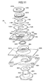
- FIG. 11 is an exploded perspective diagram of the hinge device 4A.
- FIG. 12 is an exploded perspective diagram seen from a different angle from that of FIG. 11.
- the hinge device 4A comprises a first turning member 60A into which a pivot 63A is incorporated, and a second turning member 70A having a pivot opening 71A into which the pivot 63A is inserted.
- the fist turning member 60A and the second turning member 70A can turn relatively about the axial line 41A (the center of axle of the pivot 63A) as the center of turn.
- the first turning member 60A is attached to the first housing 2A.
- the second turning member 70A is attached to a hinge cover 170A (third housing), which is joined to the second housing 3A through a hinge unit 190A, etc. This enables the hinge cover 170A and the second housing 3A to turn relatively to the first housing 2A about the axial line 41 A.
- a flange 61 A is formed integrally with the pivot 63A at the start end of the pivot 63A.
- a turn stopper 62A is formed at a portion of the rim of the flange 61A.
- the first turning member 60A has a plate-like shape.
- a concave 51A is formed in one surface (the surface to be attached to the first housing 2A) of the first turning member 60A.
- An insertion opening 53A is formed through from the bottom of the concave 51A to the opposite surface.
- a locking recess 52A is concavely formed in a portion of the wall of the concave 51A.
- the pivot 63A is inserted into the insertion opening 53A from the side of the surface in which the concave 51A is formed.
- the leading end of the pivot 63A projects to the other surface of the first turning member 60A.
- the start end of the pivot 63A is locked with the flange 61A fitted in the concave 51A and the turn stopper 62A fitted in the locking recess 52A.
- the first turning member 60A is fixed on the pivot 63A so as not to turn about the axial line 41A.
- the first turning member 60A and the pivot 63A are separate components, they may be formed integrally.
- a plate 160A is overlaid on the other surface (the surface at a side where the second turning member 70A is to be attached) of the first turning member 60A.
- the plate 160A is for concealing screw holes formed at the four corners of the first turning member 60A.
- An opening 161 A is formed in the plate 160A.
- a through hole 68A runs through inside the pivot 63A along the center of axle.
- a portion 64A of the pivot 63A that is close to the start end of the pivot 63A is formed in a cylindrical shape.
- a portion 65A of the pivot 63A that is close to the leading end of the pivot 63A is formed in a tubular shape.
- tubular is used to be distinguished from the aforesaid "cylindrical”. That is, the shape of the portion 65A close to the leading end is not circular, but the distance from the axial line 41A to a given point on the circumferential surface of the portion 65A is different from the distance from the axial line 41 A to another point on the circumferential surface of the portion 65A.
- portion 64A of the pivot 63A that is close to the bottom will be referred to as cylindrical portion 64A
- portion 65A close to the leading end will be referred to as polygonal tubular portion 65A.
- a flange 66A is formed o the leading end of the pivot 63A.
- the flange 66A is formed by the leading end of the pivot 63A being staked after the hinge device 4A is assembled. Therefore, the flange 66A on the leading end of the pivot 63A is not formed before the hinge device 4A is assembled.
- the pivot 63A is inserted through the insertion opening 53A of the first turning member 60A, the opening 161A of the plate 160A, a ring-shaped waterproof member 90A, a plain washer 100A, the pivot opening 71 A of the second turning member 70A, a first click ring 110A, a second click ring 116A, a ring-shaped disk spring 120A, and a washer 130A, in this order.
- the plain washer 100A strikes the upper end surface of the cylindrical portion 64A.
- the waterproof member 90A forms a generally cylindrical shape, and has its upper end portion, which strikes the lower surface of the second turning member 70A, stretch like a trumpet.
- the waterproof member 90A is made of rubber relatively hard.
- the cylindrical portion 64A of the pivot 63A is fitted inside the waterproof member 90A.
- the inner diameter of the waterproof function 90A is equal to the outer diameter of the cylindrical portion 64A of the pivot 63A.
- the waterproof member 90A strikes the first turning member 60A.
- a circular concave 72A is formed in one surface (the surface at the side of the first turning member 60A) of the second turning member 70A.
- the pivot opening 71A is bored from the bottom of the concave 72A to the surface at the other side of the second turning member 70A.
- the waterproof member 90A is accommodated in the concave 72A, and strikes the bottom of the concave 72A so as to surround the pivot opening 71 A.
- the diameter of the pivot opening 71 A is smaller than the inner diameter of the waterproof member 90A.
- the waterproof member 90A is sandwiched between the bottom of the concave 72A and the first turning member 60A. Being sandwiched between the bottom of the concave 72A and the first turning member 60A, the waterproof member 90A is slightly compressed and deformed.
- the plain washer 100A is sandwiched between the bottom of the concave 72A and the upper end surface of the cylindrical portion 64A.
- a circular concave 75A is formed in the surface at the other side of the second turning member 70A around the pivot opening 71A.
- Two locking recesses 76A are formed in portions of the wall of the concave 75A.
- the first click ring 110A is fitted in the concave 75A.
- Two turn stoppers 113A are formed at portions of the rim of the first click ring 110A. These turn stoppers 113A are fitted into the locking recesses 76A respectively.
- the first click ring 110A is fixed so as not to turn relatively to the second turning member 70A about the axial line 41A.
- the pivot 63A can turn relatively to the first click ring 110A and the second turning member 70A about the axial line 41A.
- the shape of an opening 117A of the second click ring 116A matches the shape of the outer circumference of the polygonal tubular portion 65A of the pivot 63A.
- the polygonal tubular portion 65A is fitted into this opening 117A.
- the second click ring 116A is fixed so as not to turn relatively to the pivot 63A.
- the pivot 63A and the second click ring 116A turn integrally. In the state that the pivot 63A is inserted through the first click ring 110A and the second click ring 116A, the first click ring 110A and the second click ring 116A are in contact with each other.
- Two convexes 112A are formed on one surface (the surface at the side of the second click ring 116A) of the first click ring 110A.
- the two convexes 112A are positioned 180-degrees apart with respect to the axial line 41A.
- Two concaves 118A are formed in one surface (the surface at the side of the first click ring 110A) of the second click ring 116A. As the first click ring 110A and the second click ring 116A turn relatively to each other, the convexes 112A slip from the concaves 118A or click in the concaves 118A again.
- the disk spring 120A is annular.
- the disk spring 120A is independent from the pivot 63A.
- the disk spring 120A is inclined to a plane orthogonal to the axial line 41A, and thereby elastically deformed in the direction of the axial line 41 A.
- the shape of an opening 131A of the washer 130A matches the shape of the outer circumference of the polygonal tubular portion 65A of the pivot 63A.
- the polygonal tubular portion 65A is fitted in this opening 131A.
- the washer 130A is fixed so as not to turn relatively to the pivot 63A.
- the washer 130A and the second click ring 116A turn integrally.
- the flange 66A of the pivot 63A strikes the washer 130A around the opening 131A of the washer 130A.
- the first click ring 110A, the second click ring 116A, the disk spring 120A, and the washer 130A are sandwiched between the flange 66A and the bottom of the concave 75A.
- the waterproof member 90A, the bottom of the concave 75A (or the bottom of the concave 72A), the first click ring 110A, the second click ring 116A, the disk spring 120A, and the washer 130A are sandwiched between the flange 66A and the first turning member 60A.
- the flange 61A and the flange 66A prevent the pivot 63A from slipping from the first turning member 60A, the second turning member 70A, the plate 160A, the waterproof member 90A, the plain washer 100A, the first click ring 110A, the second click ring 116A, the disk spring 120A, and the washer 130A.
- the disk spring 120A and the waterproof member 90A are slightly compressed and deformed. Since the waterproof member 90A is pressured to contact the bottom of the concave 72A and the first turning member 60A around the pivot opening 71 A, even if water enters from outside through a gap between the upper surface of the first turning member 60A and the lower surface of the second turning member 70A, the water can be prohibited from entering the pivot opening 71 A.
- a stopper 67A is convexly formed on one surface (the surface at the side of the second turning member 70A) of the first turning member 60A around the insertion opening 53A.
- the stopper 67A is provided in the shape of an arc whose center is on the axial line 41 A.
- a stopper 77A is convexly formed in one surface (the surface at the side of the first turning member 60A) of the second turning member 70A around the concave 72A.
- the stopper 77A is formed in the shape of an arch whose center is on the axial line 41 A.
- the stopper 67A and the stopper 77A exist on the circumference of the same circle, whose center is on the axial line 41 A.
- the total of the angle of the arc of the stopper 67A and the angle of the arc of the stopper 77A is 180 degrees.
- the range in which the stopper 67A can turn from the state that one end of the stopper 67A in the circumferential direction strikes one end of the stopper 77A in the circumferential direction to the state that the other end of the stopper 67A in the circumferential direction strikes the other end of the stopper 77A in the circumferential direction is 180 degrees.
- the second turning member 70A is stopped from turning clockwise relatively to the first turning member 60A, as the stopper 67A has its one end in the circumferential direction strike one end of the stopper 77A in the circumferential direction.
- the convexes 112A slip from the concaves 118A.
- the convexes 112A force a gap between the first click ring 110A and the second click ring 116A. Since the disk spring 120A is deformed in response to this, the user can feel the repulsive force of the disk spring 120A as a clicking touch.
- the waterproof member 90A slides on the bottom surface of the concave 72A of the second turning member 70A.
- the portion of the waterproof member 90A that contacts the bottom surface of the concave 72A is the upper end portion that stretches like a trumpet and since this portion is pressured to contact the bottom surface of the concave 72A, the waterproofed state is maintained.
- FIG. 13 is an exploded perspective diagram of the portable phone 1A.
- FIG. 14 is a diagram showing an exploded state of the cross sectional diagram of FIG. 9.
- an attaching concave 26A is formed in the front surface of the first housing 2A.
- An opening 25A is bored from the bottom of the attaching concave 26A into the inside of the first housing 2A.
- a ring-shaped groove 27A is concavely formed around the opening 25A.
- a ring-shaped packing 28A is embedded in the groove 27A.
- the first turning member 60A of the hinge device 4A is fitted in the attaching concave 26A.
- the packing 28A is sandwiched between the flange 61A and the first housing 2A.
- the packing 28A is made of elastic material such as rubber, etc. Then, the first turning member 60A is threaded to the first housing 2A by screws. Hence, the hinge device 4A is attached on the first housing 2A.
- the packing 28A is compressed.
- the first turning member 60A is screwed to the first housing 2A, in a state that the screw holes formed at the four corners of the first turning member 60A are exposed by the second turning member 70A and the plate 160A being turned by 90 degrees relatively to the first turning member 60A.
- the flange 66A, the washer 130A, the disk spring 120A, and the second click ring 116A of the hinge device 4A are fitted inside a rubber ring 180A.
- the rubber ring 180A has tab hooks 181 A.
- Tabs 78A are formed on the second turning member 70A. With this structure, the rubber ring 180A is secured to the hinge device 4A with the tabs 78A locked on the tab hooks 11A.
- the hinge cover 170A has an inner space 171 A to accommodate a part of the hinge device 4A at the side of the second turning member 70A.
- the inner space 171A is opened free, at the lower surface of the hinge cover 170A.
- the part of the hinge device 4A at the side of the second turning member 70A is accommodated into the inner space 171 A from the free opening at the lower side of the inner space 171A, with a ring-shaped packing 185A attached on the hinge device 4A.
- the packing 185A is made of elastic material such as rubber, etc.
- the second turning member 70A of the hinge device 4A is fixed on the lower surface of the hinge cover 170A by screws. Thereby, the hinge cover 170A and the first housing 2A are joined. That is, the hinge cover 170A and the first housing 2A are joined via the hinge device 4A. Therefore, the hinge cover 170A is able to turn relatively to the first housing 2A about the axial line 41 A (the center of axle of the pivot 63A).
- the ring-shaped packing 185A is compressed between the second turning member 70A and the hinge cover 170A. Accordingly, water is prohibited from entering the inner space 171A if there is water in the gap between the second turning member 70A and the hinge cover 170A.
- the second turning member 70A of the hinge device 4A is screwed to the hinge cover 170A, in a state that screw holes formed at four corners of the second turning member 70A are exposed by the second turning member 70A being turned by 90 degrees relatively to the first turning member 60A.
- a through hole 172A is formed in the wall of the hinge cover 170A at the left-hand side of the drawing.
- the through hole 172A communicates with the inner space 171A.
- a concave 173A is formed in the right-hand wall of the hinge cover 170A. The concave 173A does not communicate with the inner space 171A.
- Supports 32A and 34A for sandwiching the hinge cover 170A are formed on the end of the second housing 3A.
- one support 32A has a pivot opening 33A formed therein so as to penetrate therethrough in the direction of the axial line 42A.
- the other support 34A also has a pivot opening 35A formed therein so as to penetrate therethrough in the direction of the axial line 42A.
- the hinge unit 190A penetrates through the pivot opening 35A from the right to the left of the drawing to be further inserted into the concave 173A.
- the hinge unit 190A comprises a first fitting portion 191 A which is supported by the support 34A while being fitted in the pivot opening 35A, and a second fitting portion 192A which is supported by the hinge cover 170A while being fitted in the concave 173A.
- the first fitting portion 191A can turn relatively to the second fitting portion 192A about the axial line 42A.
- a cover 201A is placed at the right-hand side of the support 34A. The cover 201A closes the pivot opening 35A.
- an axial rod may be used to obtain a simplified structure in which the axial rod can turn relatively to one or both of the hinge cover 170A and the support 34A.
- a ring-shaped waterproof material 210A is sandwiched between the hinge cover 170A and the support 32A.
- the waterproof material 210A surrounds the pivot opening 33A and the through hole 172A.
- An axial member 220A goes through the through hole 172A leftward from the inner space 171A to be further inserted into the pivot opening 33A and the waterproof material 210A.
- the axial member 220A can turn relatively to one or both of the hinge cover 170A and the support 32A.
- the hinge cover 170A is joined to the first housing 2A by the hinge device 4A and also joined to the second housing 3A by the axial member 220A and the hinge unit 190A. Accordingly, the hinge cover 170A and the second housing 3A joined to the hinge cover 170A are enabled to turn relatively to the first housing 2A about the axial line 41A (the center of axle of the pivot 63A), and the second housing 3A is enabled to turn relatively to the hinge cover 170A and the first housing 2A joined to the hinge cover 170A about the axial line 42A (the center of axle of the axial member 220A and hinge unit 190A).
- a packing 221A is sandwiched between the axial member 220A and the wall of the through hole 172A. This keeps them watertight.
- a cover 202A is put over the support 32A at its left-hand side in the drawing. The cover 202A closes the pivot opening 33A.
- a ring-shaped packing 203A is sandwiched between the cover 202A and the support 32A around the pivot opening 33A. The packing 203A keeps the watertightness.
- a connecter 151A at one end of a wire 150A is connected to a circuit board inside the first housing 2A.
- the wire 150A is let through the through hole 68A of the pivot 63A.
- the wire 150A is, for example, a bundle of thin coaxial cables.
- the axial member 220A has a through hole 222A formed thereinside along its axial line.
- the wire 150A is let into this through hole 222A from the through hole 68A via the inner space 171 A.
- the pivot opening 33A of the support 32A communicates with the interior of the second housing 3A.
- the wire 150A extends into the interior of the second housing 3A from the through hole 222A via the pivot opening 33A. Then, a connecter 152A at the other end of the wire 150A is connected to a circuit board inside the second housing 3A.
- the connecter 152A is placed inside the second housing 3A.
- the hinge cover 170A is inserted between the support 32A and the support 34A. Then, the axial member 220A is fitted into the through hole 172A and the pivot hole 33A from the inside of the hinge cover 170A. The hinge unit 190A is fitted into the pivot opening 35A and the concave 173A.
- the flange 66A, the washer 130A, the disk spring 120A, and the second click ring 116A of the hinge device 4A are fitted inside the rubber ring 180A, and the tabs 78 are locked on the tab hooks 181A.
- the packing 185A is attached on the hinge device 4A.
- the packing 28A is fitted in the groove 27A, the wire 150A is let through the opening 25A, and the first turning member 60A is fitted in the attaching concave 26A.
- the first turning member 60A is secured on the first housing 2 by screws.
- the second turning member 70A and the plate 160A are turned by 90 degrees relatively to the first turning member 60A to expose the screw holes formed at the four corners of the first turning member 60A, and thereafter the first turning member 60A is screwed from its side.
- water that enters through the gap between the first turning member 60A and the second turning member 70A of the hinge device 4 can be prevented by the waterproof member 90A from entering the inside of the hinge cover 170A through the pivot opening 71 A of the second turning member 70A.
- water that enters through the gap between the second turning member 70A of the hinge device 4A and the hinge cover 170A can be prevented by the packing 185A from entering the inner space 171A of the hinge cover 170A.
- water that enters through the gap between the support 32A of the second housing 3A and the cover 202A can be prevented by the packing 203A from entering the pivot opening 33A and the second housing 3A.
- the first turning member 60 is fixed on the first housing 2 and the second turning member 70 is fixed on the second housing 3.
- the first turning member 60 may be fixed on the second housing 3 and the second turning member 70 may be fixed on the first housing 2.
- the first turning member 60A is fixed on the first housing 2A and the second turning member 70A is fixed on the hinge cover 170A.
- the first turning member 60 may be fixed on the hinge cover 170A and the second turning member 70 may be fixed on the first housing 2.
- the shapes of the first turning members 60 and 60A and second turning members 70 and 70A may be arbitrarily changed according to how these members are attached to the housings. Further, the shapes and arrangement positions of the packings, as the waterproofing means between the first turning members 60 and 60A or the second turning members 70 and 70A and the housings to which they are attached, may be arbitrarily changed according to the shapes and attaching methods of the first turning members 60 and 60A and second turning members 70 and 70A.
- the hinge device 4A exemplified in the second embodiment is used as the hinge device for joining the first housing 2 and the second housing 3 of the first embodiment
- at least one of the first turning member 60A and the second turning member 70A needs to be screwed from the inside of the housing.
- the packing 28A or the packing 185A need to be provided more externally than the screwed portions.
- the body of the waterproof members 90 and 90A for waterproofing the pivot openings 71 and 71A of the hinge devices 4 and 4A forms a generally cylindrical shape, and the upper end portion thereof stretches like a trumpet.
- the waterproof members 90 and 90A may have their lower end portion, which strikes the upper surface of the first turning members 60 and 60A, stretch like a trumpet, or may have both the upper and lower end portions stretch like a trumpet.
- the first embodiment and the second embodiment described above have been explained by employing a portable phone as the portable electronic apparatus.
- the present invention can be applied to a laptop personal computer, a digital camera, a video camera, a wristwatch, a PDA (Personal Digital Assistant), an electronic diary, a portable wireless device, and other electronic apparatuses, as long as they are a portable electronic apparatus which comprises a first housing and a second housing, which can turn while kept in parallel with each other.
Landscapes
- Engineering & Computer Science (AREA)
- Theoretical Computer Science (AREA)
- Computer Hardware Design (AREA)
- Physics & Mathematics (AREA)
- General Engineering & Computer Science (AREA)
- Human Computer Interaction (AREA)
- General Physics & Mathematics (AREA)
- Signal Processing (AREA)
- Mathematical Physics (AREA)
- Computer Networks & Wireless Communication (AREA)
- Telephone Set Structure (AREA)
- Pivots And Pivotal Connections (AREA)
Abstract
Description
- The present invention relates to a hinge device which joins a first housing and a second housing of a portable electronic apparatus in a manner that the first housing and the second housing can turn around kept in generally parallel with each other, and a portable electronic apparatus using the hinge device.
- Recent portable electronic apparatuses such as portable phones include ones that have a first housing and a second housing, which turn around while being kept in generally parallel with each other (e.g., see Unexamined
Japanese Patent Application KOKAI Publication No. 2004-270821 - The structure of such a hinge device is as follows.
- (1) A first base is fixed on the first housing. (2) A second base is fixed on the second housing. (3) A pivot is fixed on the first base, and is pivotally supported by the second base. In this case, the pivot is inserted through a pivot opening in the second base. The radial load of the pivot is received by the second base. (4) A wire is provided in a way that it runs through a through hole provided along the axial line of the pivot. This wire electrically connects the circuit board in the first housing and the circuit board in the second housing.
- Further known among such portable electronic apparatuses as described above are ones that can have their first housing and second housing turn around relatively not only about the above-described axial line (i.e., the axial line that runs orthogonally to the facing surfaces of the first housing and second housing), but also around an axial line that is orthogonal to the above-described axial line (e.g., see Unexamined
Japanese Patent Application KOKAI Publication No. 2005-127449 - In such a portable electronic apparatus as described above, the hinge device needs to have a waterproof function, because external water might enter the first housing and the second housing though a gap in the pivot opening and the through hole.
- The present invention was made in view of the above-described problem, and an object of the present invention is to provide a hinge device having a sufficient waterproof function and a portable electronic apparatus.
- To achieve above object, a hinge device (4, 4A) according to the present invention comprises: a first member (60, 60A) having a pivot (63, 63A) in which a through hole (68, 68A) is formed in a direction of axis of the pivot (63, 63A), a second member (70, 70A) having a pivot opening (71, 71A) into which the pivot (63, 63A) is inserted and capable of turning relatively to the first member (60, 60A) about the pivot (63, 63A) as a center of turn, and a waterproof member (90, 90A) formed in a ring shape and sandwiched between the first member (60, 60A) and the second member (70, 70A) so as to surround the pivot (63, 63A) and the pivot opening.
- A portable electronic apparatus (1, 1A) according to the present invention is a portable electronic apparatus (1, 1 A) having a first housing (2, 2A), a second housing (3, 3A), and a hinge device (4, 4A) which joins the first housing (2, 2A) and the second housing (3, 3A) in a manner that the first housing (2, 2A) and the second housing (3, 3A) are capable of turning about an axial line (41, 41A) orthogonal to a front surface of the first housing (2, 2A), wherein the hinge device (4, 4A) comprises: a first member (60, 60A) having a pivot (63, 63A) in which a through hole (68, 68A) is formed in a direction of axis of the pivot (63, 63A); a second member (70, 70A) having a pivot opening (71, 71A) into which the pivot (63, 63A) is inserted and capable of turning relatively to the first member (60, 60A) about the pivot (63, 63A) as a center of turn; and a waterproof member (90, 90A) formed in a ring shape and sandwiched between the first member (60, 60A) and the second member (70, 70A) so as to surround the pivot (63, 63A) and the pivot opening (71, 71A), and wherein one of the first member (60, 60A) and the second member (70, 70A) is attached to the first housing (2, 2A) with a first waterproof packing (67, 28A) provided between them, and the other is attached to the second housing (3, 3A) or a third housing (170A) joined to the second housing (3A) with a second waterproof packing (74, 185A) provided between them.
- According to the present invention, since the ring-shaped waterproof member is sandwiched between the first turning member and the second turning member so as to surround the pivot and the pivot opening, external water that enters through the gap between the first turning member (60A) and the second turning member (70A) can be prevented from flowing into the pivot opening.
- Since the present invention comprises the through hole inside the pivot, in a case
where, for example, electric circuits are provided inside the first housing and the second housing respectively, the wire to connect these electric circuits can be suitably provided through the hinge device of the present invention. This is because the wire can be let through the through hole. In such a state, the existence of this wire would not hinder the turning movements that would be realized by the hinge device of the present invention. - These objects and other objects and advantages of the present invention will become more apparent upon reading of the following detailed description and the accompanying drawings in which:
- FIGS. 1A to 1C are perspective diagrams of a portable phone according to a first embodiment;
- FIG. 2 is a front elevation of the portable phone according to the first embodiment;
- FIG. 3 is a cross sectional diagram on arrow along a line III-III of FIG. 2;
- FIG. 4 is an exploded perspective diagram of a hinge device according to the first embodiment;
- FIG. 5 is an exploded perspective diagram seen from a different angle from that of FIG. 4;
- FIG. 6 is an exploded perspective diagram of the portable phone according to the first embodiment;
- FIGS. 7A to 7C are perspective diagrams of a portable phone according to a second embodiment;
- FIGS. 8A to 8D are perspective diagrams of the portable phone according to the second embodiment;
- FIG. 9 is a cross sectional diagram on arrow along an
axial line 42A of FIG. 7B; - FIG. 10 is a perspective diagram showing a hinge device according to the second embodiment in a broken state;
- FIG. 11 is an exploded perspective diagram of the hinge device according to the second embodiment;
- FIG. 12 is an exploded perspective diagram seen from a different angle from that of FIG. 11;
- FIG. 13 is an exploded perspective diagram of the portable phone according to the second embodiment; and
- FIG. 14 is a diagram showing an exploded state of the portion shown in the cross sectional diagram of FIG. 9.
- The best mode for carrying out the present invention will be explained below using the drawings. It should be noted that the embodiments to be described below include various limitations that are technically preferable for the present invention to be carried out, but these are not intended to limit the scope of the present invention to the embodiments and illustrated examples below.
- FIGS. 1A to 1C are perspective diagrams of a
portable phone 1. FIG. 2 is a front elevation of theportable phone 1. FIG. 3 is a cross sectional view on arrow along a line III-III shown in FIG. 2. - As shown in FIGS. 1 to 3, the
portable phone 1 comprises afirst housing 2, asecond housing 3, and ahinge device 4 that joins thefirst housing 2 and thesecond housing 3. Thefirst housing 2 comprises afront case 22 and arear case 23, which are fitted together with a rubberwaterproof ring 24 between them. Thesecond housing 3 comprises afront case 32 and arear case 3, which are fitted together with a rubberwaterproof ring 34 between them. - A
key operation section 21 is provided on the front surface of thefirst housing 2. Thekey operation section 21 includes, for example, ten keys and other function keys. The edges of a key rubber for thekey operation section 21 is adhered onto the internal surface of thefront case 22, or thewaterproof ring 24 is provided on the edges of a key rubber, so thekey operation section 21 is waterproofed. - A
transparent display window 31 is formed on the front surface of thesecond housing 3. A display panel is contained inside thesecond housing 3, and the display surface of the display panel faces thedisplay window 31. Akey operation section 36 is provided on the front surface of thesecond housing 3. Thekey operation section 36 includes a cursor key. Thekey operation section 36 is waterproofed, with the edges of akey rubber 37 adhered on the internal surface of akey plate 38, which is attached on the top surface of thefront case 32. - The
hinge device 4 joins thefirst housing 2 and thesecond housing 3 in a state that the front surface of thefirst housing 2 and the rear surface of thesecond housing 3 face each other. Anaxial line 41 of thehinge device 4 is orthogonal to the front and rear surfaces of thesecond housing 3 and the front and rear surfaces of thefirst housing 2. Thehinge device 4 makes thesecond housing 3 or thefirst housing 2 capable of turning around with respect to thefirst housing 2 or thesecond housing 3, while being kept in a state that the rear surface of thesecond housing 3 is generally parallel with the front surface of thefirst housing 2. - FIG. 1A shows a state that the outer rim of the
second housing 3 comes exactly upon the outer rim of thefirst housing 2, when seen in the direction of theaxial line 41. FIG. 1C shows a state that thesecond housing 3 turns by 180 degrees from the state of FIG. 1A. FIG. 1B shows a state that is seen between when the state is as shown in FIG. 1A and when the state is as shown in FIG. 1C. - The
first housing 2 and thesecond housing 3 can turn around relatively to each other, as described above. In the following description, one-sided expressions like "thesecond housing 3 turns relatively to thefirst housing 2" and "thefirst housing 2 turns relatively to thesecond housing 3" might be possibly used to simplify the explanation. However, the readers should be reminded that such an expression will just imply that both of them can turn around relatively to each other. - The
hinge device 4 comprises two turning members which turn relatively to each other about theaxial line 41 as the center of turn. One of the two turning members is attached on thefirst housing 2, and the other is attached on thesecond housing 3. - Next, the structure of the
hinge device 4 will be specifically explained with reference to FIGS. 3 to 5. FIG. 4 is an exploded perspective diagram of thehinge device 4, and FIG. 5 is another exploded perspective diagram seen from a different angle from that of FIG. 4. - As shown in FIGS. 3 to 5, the
hinge device 4 comprises afirst turning member 60 having apivot 63, and asecond turning member 70 having apivot opening 71, through which thepivot 63 is inserted. Though the details will be described later, thepivot 63 is protected from falling off thepivot opening 71 when it is inserted through thepivot opening 71. In this state, the first turningmember 60 and thesecond turning member 70 can turn relatively to each other about the axial line 41 (the center of axle of the pivot 63) as the center of turn. - The
first turning member 60 has a generally bottomed-cylindrical shape. Thefirst turning member 60 is internally stepped. That is, the inner diameter of the first turningmember 60 at a side closer to the bottom 6 is smaller than that at a side closer to the free opening of the first turningmember 60. - Inside the first turning
member 60, thepivot 63 projects from the bottom 61 of the first turningmember 60 in the direction perpendicular to the bottom 61. Thepivot 63 is formed integrally with the first turningmember 60. - A
groove 62 is concavely formed in the outer circumferential surface of the first turningmember 60, in the circumferential direction. Thegroove 62 is provided for abracket 50 to be fitted therein. Thebracket 50 is a supplementary member for attaching the first turningmember 60 to thefirst housing 2. Thebracket 50 has acutout 51, which is open at an edge of thebracket 50. The edge portion of thecutout 51 is fitted into thegroove 62. It is inside thefirst housing 2, where thebracket 50 is fitted into thegroove 62. The depth of thegroove 62 is not uniform, so that thebracket 50 may not turn with respect to the first turningmember 60 when thebracket 50 is fitted in thegroove 62. - The
bracket 50 is fixed on the internal surface of thefront case 22 of thefirst housing 2 by screws or the like. Thus, the first turningmember 60 is fixed on thefirst housing 2. - Another groove is concavely formed in the outer circumferential surface of the first turning
member 60 in the circumferential direction, and a ring-shaped first packing 67 is fitted in the groove. Thefirst packing 67 is for waterproofing an opening 25 (see FIG. 6) formed in thefront case 22 of thefirst housing 2, and is made of elastic material such as rubber, etc. - A through
hole 68 runs through inside thepivot 63 along theaxial line 41. Aportion 64 of thepivot 63 that is close to the bottom of thepivot 63 is formed in a cylindrical shape. - On the other hand, a
portion 65 of thepivot 63 that is close to the leading end of thepivot 63 is formed in a tubular shape. Here, the term "tubular" is used to be distinguished from the aforesaid "cylindrical". That is, theportion 65 close to the leading end is not circumferentially circular, but the distance from theaxial line 41 to a given point on the circumferential surface of theportion 65 is different from the distance from theaxial line 41 to another point on the circumferential surface of theportion 65. - With these things taken into consideration, the
portion 64 closer to the bottom of thepivot 63 will be referred to ascylindrical portion 64 and theportion 65 closer to the leading end will be referred to as polygonaltubular portion 65. - In FIGS. 3 to 5, a
flange 66 is formed on the leading end of thepivot 63. Thisflange 66 is formed by the leading end of thepivot 63 being staked after thehinge device 4 is assembled. Hence, theflange 66 on the leading end of thepivot 63 is not formed before thehinge device 4 is assembled. - The
pivot 63 is inserted through a ring-shapedwaterproof member 90, aplain washer 100, the pivot opening 71 of thesecond turning member 70, aclick ring 110, a ring-shapeddisk spring 120, a ring-shapedstopper 130, and a ring-shaped restrictingmember 140, in this order. - The
plain washer 100 strikes the top end surface of thecylindrical portion 64. - The
waterproof member 90 forms a generally cylindrical shape, and has its upper end portion, which strikes the lower surface of thesecond turning member 70, stretch like a trumpet. Thewaterproof member 90 is made of rubber relatively hard. Thecylindrical portion 64 of thepivot 63 can fit in thewaterproof member 90. The inner diameter of thewaterproof member 90 is equal to the outer diameter of thecylindrical portion 64 of thepivot 63. Thewaterproof member 90 strikes the bottom 61 of the first turningmember 61. - The
pivot opening 71 of thesecond turning member 70 penetrates through generally the center portion of thesecond turning member 70. Thepivot opening 71 penetrates through the center portion of acircular boss 72, which is formed to project from one surface (the surface at the side of the first turning member 60) of thesecond turning member 70. The outer diameter of theboss 72 is larger than the outer diameter of the first turningmember 60. A ring-shaped convex 73 is formed on the lower end surface of theboss 72 along the rim of theboss 72. A groove is formed in the outer circumferential surface of theboss 72 in the circumferential direction, and a ring-shaped second packing 74 is fitted in the groove. Thesecond packing 74 is for waterproofing an opening 35 (see FIG. 6) formed in therear case 33 of thesecond hosing 3, and is made of elastic material such as rubber, etc. - In the state that the
pivot 63 is inserted through thepivot opening 71, a part of theboss 72 is fitted in the first turningmember 60, and the ring-shaped convex 73 strikes the step, which links the smaller-diameter portion of the first turningmember 60 that is closer to the bottom 61 and the larger-diameter portion that is closer to the free opening of the first turningmember 60. - The diameter of the
pivot opening 71 is smaller than the inner diameter of thewaterproof member 90, and the upper end portion of thewaterproof member 90 that stretches like a trumpet strikes the lower end surface of theboss 72 so as to surround thepivot opening 71. Thewaterproof member 90 is sandwiched between the lower end surface of theboss 72 and the bottom 61 of the first turningmember 60. Being sandwiched between the lower end surface of theboss 72 and the bottom 61 of the first turningmember 60, thewaterproof member 90 is compressed and deformed, though slightly. - The
plain washer 100 is sandwiched between the lower end surface of theboss 72 and the upper surface of thecylindrical portion 64. - A circular stepped concave 75 is formed in the other surface of the
second turning member 70 around thepivot opening 71. Twoconvexes 76 are formed on the deeper bottom of the stepped concave 75, and these twoconvexes 76 are positioned 180-degrees apart with respect to theaxial line 41. Aprojection 77 is formed on the shallower bottom of the stepped concave 75. Theprojection 77 is positioned 90-degrees apart from theconvexes 76 with respect to theaxial line 41. - The shape of an
opening 111 of theclick ring 110 matches the shape of the outer circumference of the polygonaltubular portion 65 of thepivot 63, and the polygonaltubular portion 65 is fitted into thisopening 111. Thus, theclick ring 110 is fixed on thepivot 63, and thepivot 63 and theclick ring 110 can turn integrally. Theclick ring 110 strikes the bottom of the stepped concave 75. Twoconcaves 112 are formed in the surface of theclick ring 110 that strikes that bottom. The twoconcaves 112 are positioned 180-degrees apart with respect to theaxial lie 41. Theconvexes 76 enters theconcaves 112. Theconvexes 76 slip from theconcaves 112 when theclick ring 110 turns. - The outer circumference of the
click ring 110 is circular. Theclick ring 110 has its radial load received by the wall of the stepped concave 75 to have thepivot 63 pivotally supported. - The
disk spring 120 is annular, and independent from thepivot 63. Thedisk spring 120 is inclined to a plane orthogonal to theaxial line 41, and thereby elastically deformed in the direction of theaxial line 41. - The diameter of the
stopper 130 is larger than the diameter of thedisk spring 120, so thedisk spring 120 is inside thestopper 130. Aprojection 131 is formed on one surface of thestopper 130, and aprojection 132 is also formed on the other surface thereof. Thestopper 130 is inserted to the shallower bottom of the stepped concave 75. - The shape of an
opening 141 of the restrictingmember 140 matches the shape of the outer circumference of the polygonaltubular portion 65 of thepivot 63, and the polygonaltubular portion 65 is fitted in theopening 141. The restrictingmember 140 is thereby fixed on thepivot 63, and the restrictingmember 140 and theclick ring 110 turn integrally. An arcingcutout 142 is formed in the rim of the restrictingmember 140, and theprojection 132 of thestopper 130 is somewhere in thiscutout 142. Thecutout 142, theprojection 132, theprojection 131, and theprojection 77 restrict the turning angle to slightly larger than a limit of 180 degrees. - The
flange 66 of thepivot 63 strikes the restrictingmember 140 around theopening 141 of the restrictingmember 140. Theclick ring 110, thedisk spring 120, and the restrictingmember 140 are sandwiched between theflange 66 and the deeper bottom of the stepped concave 75. Further, thewaterproof member 90, the bottom of the stepped concave 75 (or the lower end surface of the boss 72), theclick ring 110, thedisk spring 120, and the restrictingmember 140 are sandwiched between theflange 66 and the bottom 61 of the first turningmember 60. In this manner, theflange 66 prevents thepivot 63 from slipping from thesecond turning member 70, thewaterproof member 90, theplain washer 100, theclick ring 110, thedisk spring 120, thestopper 130, and the restrictingmember 140. - The
disk spring 120 and thewaterproof member 90 are slightly compressed and deformed in this sandwiched state. Since thewaterproof member 90 is pressured to contact the lower end surface of theboss 72 and the bottom 61 of the first turningmember 60 around thepivot opening 71, even if water enters from outside through the gap between the inner wall of the free opening of the first turningmember 60 and the outer wall of the ring-shaped convex 73 of thesecond turning member 70, the water can be prohibited from entering thepivot opening 71. - The working of the
hinge device 4 will be explained. - The state shown in FIG. 4 corresponds to the state shown in FIG. 1C. In this state, the
convexes 76 enter theconcaves 112 of theclick ring 110. Further, in this state, since theprojection 132 of the stopper strikes oneend 143 of thecutout 142 and theprojection 131 strikes theprojection 77, thesecond turning member 70 can turn to one side relatively to the first turningmember 60 but cannot turn to the other side. That is, thesecond turning member 70 can only turn in a direction that is reverse to the turning direction when the state of FIG. 1A shifts to the state of FIG. 1C. - When the
second turning member 70 is caused to turn in the aforementioned direction relatively to the first turningmember 60, theconvexes 76 slip from theconcaves 112. When theconvexes 76 slip from theconcaves 112, theclick ring 110 deforms thedisk spring 120. Therefore, the user can feel the repulsive force of thedisk spring 120 as a clicking touch. - Then, when second turning
member 70 turns by 180 degrees relatively to the first turningmember 60, theconvexes 76 enter theconcaves 112 on the other sides respectively. At this time, thedisk spring 120 is restored to its original shape, and the user can feel the restoring force as a clicking touch. In this state, theprojection 77 formed on thesecond turning member 70 is at a position turned by 180 degrees from theprojection 131 of thestopper 130. Therefore, thesecond turning member 70 can turn to both the left and the right directions. - When the
second turning member 70 is caused to turn relatively to the first turningmember 60, thewaterproof member 90 slides on the lower end surface of theboss 72 of thesecond turning member 70. In this case, since the portion of thewaterproof member 90 that contacts the lower end surface of theboss 72 is the portion at the upper end that stretches like a trumpet and this portion contacts the lower end surface of theboss 72 with a pressure, the waterproofed state can be maintained. - Further, since the ring-shaped convex 73 formed on the lower surface of the
second turning member 70 strikes the step portion of the first turningmember 60 that links the smaller-diameter portion close to the bottom 61 and the larger-diameter portion close to the free opening, thesecond turning member 70 shakes less, when turning relatively to the first turningmember 60. - Next, how to attach the
hinge device 4 will be explained with reference to FIG. 3 and FIG. 6. FIG. 6 is an exploded perspective diagram of theportable phone 1. FIG. 6 mainly shows therear case 33 of thesecond housing 3, thefront case 22 of thefirst housing 2, and thehinge device 4, where thefront case 22 of thefirst housing 2 is partially broken. - As shown in FIGS. 3 and 6, a
first opening 25 is formed through thefront case 22 of thefirst housing 2, and asecond opening 35 is formed through therear case 33 of thesecond housing 3. - When the
hinge device 4 is attached to thesecond housing 3 and thefirst housing 2, thehinge device 4 is assembled beforehand. When assembled beforehand, the components of thehinge device 4 except thebracket 50 are assembled in the arrangement shown in FIG. 4, and the leading end of thepivot 63 is staked so that the components are unitized. Thefirst turning member 60 of theunitized hinge device 4 is inserted through thesecond opening 35 from the internal side of the second housing 3 (the inner surface side of the rear case 33). Thesecond turning member 70 of thehinge device 4 is fixed on the inner surface of therear case 33 of thesecond housing 3 by screws or the like. - Next, the first turning
member 60 of theunitized hinge device 4 is inserted through thefirst opening 25 from the front side of the first housing 2 (the front surface side of the front case 22). In this state, the edge portion of thecutout 51 of thebracket 50 is slid into thegroove 62. After this, thebracket 50 is fixed on the inner surface of thefront case 22 of thefirst housing 2 by screws or the like. Awire 150 is let through the throughhole 68 inside thepivot 63 after theunitized hinge device 4 is fixed on therear case 33 of thesecond housing 3 and thefront case 22 of thefirst housing 2 in the way described above. Thewire 150 is connected to a circuit board contained in thesecond housing 3 and to the circuit board contained in thefirst housing 2. For example, thewire 150 is a bundle of thin coaxial cables. FIG. 3 omits illustration of thewire 150 to make the diagram understandable. - The
rear case 23 of thefirst housing 2 is attached to thefront case 22 after the circuit board, etc. are mounted on thefront case 22 or therear case 23. Thefront case 32 of thesecond housing 3 is attached to therear case 33 after the circuit board, etc. are mounted on thefront case 32 or therear case 33. - As described above, according to the present embodiment, the
first packing 67 prevents water that comes through a gap 5 (shown in FIG. 3) between thesecond housing 3 and thefirst housing 2 from entering thefirst housing 2 through thefirst opening 25. Further, thesecond packing 74 prevents the water from thegap 5 from entering thesecond housing 3 through thesecond opening 35. Further, thewaterproof member 90 prevents the water from thegap 5 from entering thesecond housing 3 through thepivot opening 71. - According to the above-described embodiment, the illustrated
portable phone 1 is structured such that thefirst housing 2 and thesecond housing 3 can turn relatively about an axis which is orthogonal to the front and rear surfaces of these housings. However, the present invention can also be applied to a foldable electronic apparatus whosefirst housing 2 andsecond housing 3 can not only turn relatively about an axis that is orthogonal to the front and rear surfaces of the housings but can turn about an axis that is perpendicular to that axis. Such an application will be explained below as a second embodiment. - FIGS. 7 and 8 are perspective diagrams of a
portable phone 1A, and FIG. 9 is a cross sectional view on arrow along anaxial line 42A show in FIG. 7B. - As shown in FIGS. 7 to 9, the
portable phone 1A comprises afirst housing 2A, asecond housing 3A, and abiaxial hinge assembly 40A which joins thefirst housing 2A and thesecond housing 3A. Akey operation section 21A is provided on the front surface of thefirst housing 2A. Thekey operation section 21 A includes ten keys, etc. Atransparent display window 31A is provided on the front surface of thesecond housing 3A. A display panel is contained in thesecond housing 3A, and the display surface of the display panel faces thedisplay window 31 A. Likewise in the first embodiment, each of thefirst housing 2A and thesecond housing 3A has its front case and rear case fitted together with a rubber waterproof ring, though not illustrated, placed between them. - The
biaxial hinge assembly 40A has anaxial line 41A that is orthogonal to the front surface of thefirst housing 2A, and anaxial line 42A that extends in the widthwise direction of thesecond housing 3A between the front and rear surfaces of thesecond housing 3A. Theaxial line 41A and theaxial line 42A are orthogonal to each other. Thebiaxial hinge assembly 40A enables thesecond housing 3A to turn relatively to thefirst housing 2A about theaxial line 41A. The biaxial hinge assembly 40a also enables thesecond housing 3A to turn relatively to thefirst housing 2A about theaxial line 42A. As shown in FIGS. 7, thesecond housing 3A is opened from or closed to thefirst housing 2A by thesecond housing 3A being turned about theaxial line 42A. As shown in FIGS. 8, thesecond housing 3A is turned relatively to thefirst housing 2A or turned upside down by thesecond housing 3A being turned about theaxial line 41A. - FIG. 7A shows a state that the
second housing 3A and thefirst housing 2A are closed with the front surface of thesecond housing 3A facing the front surface of thefirst housing 2A. FIG. 7C shows a state that thesecond housing 3A and thefirst housing 2A are opened with the front surface of thesecond housing 3A and the front surface of thefirst housing 2A facing forward. FIG. 7B shows a state which appears between the state of FIG. 7A and the state of FIG. 7C when the housings are opened from the state of FIG. 7A to the state of FIG. 7C or closed reversely. - FIG. 8A shows a state that the
second housing 3A and thefirst housing 2A are closed with the front surface of thesecond housing 3A facing the front surface of thefirst housing 2A. FIG. 8B shows a state that thesecond housing 3A is turned about theaxial line 41A with the front surface of thesecond housing 3A facing the front surface of thefirst housing 2A. FIG. 8C shows a state that thesecond housing 3A is turned about theaxial line 42A. FIG. 8D shows a state that thesecond housing 3A and thefirst housing 2A are closed with the rear surface of thesecond housing 3A facing the front surface of thefirst housing 2A. - As shown in FIG. 9, the
biaxial hinge assembly 40A comprises ahinge device 4A which enables thesecond housing 3A to turn relatively to thefirst housing 2A about theaxial line 41A, and a hinge mechanism (ahinge unit 190A, etc.) which enables thesecond housing 3A to turn relatively to thefirst housing 2A about theaxial line 42A. - Next, the structure of the
hinge device 4A will be explained in detail with reference to FIGS. 9 to 12. FIG. 10 is a perspective diagram of thehinge device 4A which is broken along a plane that includes theaxial line 41A. FIG. 11 is an exploded perspective diagram of thehinge device 4A. FIG. 12 is an exploded perspective diagram seen from a different angle from that of FIG. 11. - As shown in FIGS. 9 to 12, the
hinge device 4A comprises afirst turning member 60A into which apivot 63A is incorporated, and asecond turning member 70A having a pivot opening 71A into which thepivot 63A is inserted. Thefist turning member 60A and thesecond turning member 70A can turn relatively about theaxial line 41A (the center of axle of thepivot 63A) as the center of turn. Thefirst turning member 60A is attached to thefirst housing 2A. Thesecond turning member 70A is attached to ahinge cover 170A (third housing), which is joined to thesecond housing 3A through ahinge unit 190A, etc. This enables thehinge cover 170A and thesecond housing 3A to turn relatively to thefirst housing 2A about theaxial line 41 A. - A
flange 61 A is formed integrally with thepivot 63A at the start end of thepivot 63A. Aturn stopper 62A is formed at a portion of the rim of theflange 61A. - The
first turning member 60A has a plate-like shape. A concave 51A is formed in one surface (the surface to be attached to thefirst housing 2A) of thefirst turning member 60A. Aninsertion opening 53A is formed through from the bottom of the concave 51A to the opposite surface. A lockingrecess 52A is concavely formed in a portion of the wall of the concave 51A. - The
pivot 63A is inserted into theinsertion opening 53A from the side of the surface in which the concave 51A is formed. The leading end of thepivot 63A projects to the other surface of thefirst turning member 60A. The start end of thepivot 63A is locked with theflange 61A fitted in the concave 51A and theturn stopper 62A fitted in thelocking recess 52A. Thereby, thefirst turning member 60A is fixed on thepivot 63A so as not to turn about theaxial line 41A. Though thefirst turning member 60A and thepivot 63A are separate components, they may be formed integrally. - A
plate 160A is overlaid on the other surface (the surface at a side where thesecond turning member 70A is to be attached) of thefirst turning member 60A. Theplate 160A is for concealing screw holes formed at the four corners of thefirst turning member 60A. Anopening 161 A is formed in theplate 160A. - A through
hole 68A runs through inside thepivot 63A along the center of axle. Aportion 64A of thepivot 63A that is close to the start end of thepivot 63A is formed in a cylindrical shape. Aportion 65A of thepivot 63A that is close to the leading end of thepivot 63A is formed in a tubular shape. Here, the term "tubular" is used to be distinguished from the aforesaid "cylindrical". That is, the shape of theportion 65A close to the leading end is not circular, but the distance from theaxial line 41A to a given point on the circumferential surface of theportion 65A is different from the distance from theaxial line 41 A to another point on the circumferential surface of theportion 65A. - Hereinafter, the
portion 64A of thepivot 63A that is close to the bottom will be referred to ascylindrical portion 64A, and theportion 65A close to the leading end will be referred to as polygonaltubular portion 65A. - In FIGS. 9 to 12, a
flange 66A is formed o the leading end of thepivot 63A. Theflange 66A is formed by the leading end of thepivot 63A being staked after thehinge device 4A is assembled. Therefore, theflange 66A on the leading end of thepivot 63A is not formed before thehinge device 4A is assembled. - The
pivot 63A is inserted through theinsertion opening 53A of thefirst turning member 60A, theopening 161A of theplate 160A, a ring-shapedwaterproof member 90A, aplain washer 100A, thepivot opening 71 A of thesecond turning member 70A, afirst click ring 110A, asecond click ring 116A, a ring-shapeddisk spring 120A, and awasher 130A, in this order. - The
plain washer 100A strikes the upper end surface of thecylindrical portion 64A. - The
waterproof member 90A forms a generally cylindrical shape, and has its upper end portion, which strikes the lower surface of thesecond turning member 70A, stretch like a trumpet. Thewaterproof member 90A is made of rubber relatively hard. Thecylindrical portion 64A of thepivot 63A is fitted inside thewaterproof member 90A. The inner diameter of thewaterproof function 90A is equal to the outer diameter of thecylindrical portion 64A of thepivot 63A. Thewaterproof member 90A strikes thefirst turning member 60A. - A circular concave 72A is formed in one surface (the surface at the side of the
first turning member 60A) of thesecond turning member 70A. Thepivot opening 71A is bored from the bottom of the concave 72A to the surface at the other side of thesecond turning member 70A. - The
waterproof member 90A is accommodated in the concave 72A, and strikes the bottom of the concave 72A so as to surround thepivot opening 71 A. The diameter of thepivot opening 71 A is smaller than the inner diameter of thewaterproof member 90A. - The
waterproof member 90A is sandwiched between the bottom of the concave 72A and thefirst turning member 60A. Being sandwiched between the bottom of the concave 72A and thefirst turning member 60A, thewaterproof member 90A is slightly compressed and deformed. - The
plain washer 100A is sandwiched between the bottom of the concave 72A and the upper end surface of thecylindrical portion 64A. - A circular concave 75A is formed in the surface at the other side of the
second turning member 70A around thepivot opening 71A. Two lockingrecesses 76A are formed in portions of the wall of the concave 75A. Thefirst click ring 110A is fitted in the concave 75A. Twoturn stoppers 113A are formed at portions of the rim of thefirst click ring 110A. Theseturn stoppers 113A are fitted into the locking recesses 76A respectively. Thereby, thefirst click ring 110A is fixed so as not to turn relatively to thesecond turning member 70A about theaxial line 41A. Thepivot 63A can turn relatively to thefirst click ring 110A and thesecond turning member 70A about theaxial line 41A. - The shape of an
opening 117A of thesecond click ring 116A matches the shape of the outer circumference of the polygonaltubular portion 65A of thepivot 63A. The polygonaltubular portion 65A is fitted into thisopening 117A. Thereby, thesecond click ring 116A is fixed so as not to turn relatively to thepivot 63A. Thepivot 63A and thesecond click ring 116A turn integrally. In the state that thepivot 63A is inserted through thefirst click ring 110A and thesecond click ring 116A, thefirst click ring 110A and thesecond click ring 116A are in contact with each other. - Two
convexes 112A are formed on one surface (the surface at the side of thesecond click ring 116A) of thefirst click ring 110A. The twoconvexes 112A are positioned 180-degrees apart with respect to theaxial line 41A. Twoconcaves 118A are formed in one surface (the surface at the side of thefirst click ring 110A) of thesecond click ring 116A. As thefirst click ring 110A and thesecond click ring 116A turn relatively to each other, theconvexes 112A slip from theconcaves 118A or click in theconcaves 118A again. - The
disk spring 120A is annular. Thedisk spring 120A is independent from thepivot 63A. Thedisk spring 120A is inclined to a plane orthogonal to theaxial line 41A, and thereby elastically deformed in the direction of theaxial line 41 A. - The shape of an
opening 131A of thewasher 130A matches the shape of the outer circumference of the polygonaltubular portion 65A of thepivot 63A. The polygonaltubular portion 65A is fitted in thisopening 131A. Thereby, thewasher 130A is fixed so as not to turn relatively to thepivot 63A. Thewasher 130A and thesecond click ring 116A turn integrally. - The
flange 66A of thepivot 63A strikes thewasher 130A around theopening 131A of thewasher 130A. Thefirst click ring 110A, thesecond click ring 116A, thedisk spring 120A, and thewasher 130A are sandwiched between theflange 66A and the bottom of the concave 75A. Further, thewaterproof member 90A, the bottom of the concave 75A (or the bottom of the concave 72A), thefirst click ring 110A, thesecond click ring 116A, thedisk spring 120A, and thewasher 130A are sandwiched between theflange 66A and thefirst turning member 60A. In this way, theflange 61A and theflange 66A prevent thepivot 63A from slipping from thefirst turning member 60A, thesecond turning member 70A, theplate 160A, thewaterproof member 90A, theplain washer 100A, thefirst click ring 110A, thesecond click ring 116A, thedisk spring 120A, and thewasher 130A. - In this sandwiched state, the
disk spring 120A and thewaterproof member 90A are slightly compressed and deformed. Since thewaterproof member 90A is pressured to contact the bottom of the concave 72A and thefirst turning member 60A around thepivot opening 71 A, even if water enters from outside through a gap between the upper surface of thefirst turning member 60A and the lower surface of thesecond turning member 70A, the water can be prohibited from entering thepivot opening 71 A. - A
stopper 67A is convexly formed on one surface (the surface at the side of thesecond turning member 70A) of thefirst turning member 60A around theinsertion opening 53A. Thestopper 67A is provided in the shape of an arc whose center is on theaxial line 41 A. - On the other hand, a
stopper 77A is convexly formed in one surface (the surface at the side of thefirst turning member 60A) of thesecond turning member 70A around the concave 72A. Thestopper 77A is formed in the shape of an arch whose center is on theaxial line 41 A. - The
stopper 67A and thestopper 77A exist on the circumference of the same circle, whose center is on theaxial line 41 A. The total of the angle of the arc of thestopper 67A and the angle of the arc of thestopper 77A is 180 degrees. Hence, the range in which thestopper 67A can turn from the state that one end of thestopper 67A in the circumferential direction strikes one end of thestopper 77A in the circumferential direction to the state that the other end of thestopper 67A in the circumferential direction strikes the other end of thestopper 77A in the circumferential direction is 180 degrees. - The working of the
hinge device 4A will be explained. - First, the
second turning member 70A is stopped from turning clockwise relatively to thefirst turning member 60A, as thestopper 67A has its one end in the circumferential direction strike one end of thestopper 77A in the circumferential direction. - Further, as the
convexes 112A click in theconcaves 118A, the elasticity of thedisk spring 120A acts to expand the distance between theflange 61 A and theflange 66A, and the resulting counteracting force squeezes the components sandwiched between theflange 61A and theflange 66A. This also stops thesecond turning member 70A from turning anticlockwise relatively to thefirst turning member 60A. This state corresponds to FIGS. 7A to 7C and FIG. 8A. - When the
second turning member 70A is caused to turn anticlockwise against the squeezing force of thedisk spring 120A, theconvexes 112A slip from theconcaves 118A. When theconvexes 112A slip from theconcaves 118A, theconvexes 112A force a gap between thefirst click ring 110A and thesecond click ring 116A. Since thedisk spring 120A is deformed in response to this, the user can feel the repulsive force of thedisk spring 120A as a clicking touch. - Then, when the
second turning member 70A is caused to turn by 180 degrees relatively to thefirst turning member 60A, theconvexes 112A click in theconcaves 118A at the opposite sides. At this time, thedisk spring 120A is restored to its original shape, and the user can feel the restoring force as a clicking touch. In this state, since the other end of thestopper 67A in the circumferential direction strikes the other end of thestopper 77A in the circumferential direction, thesecond turning member 70A is stopped from turning anticlockwise relatively to thefirst turning member 60A. This state corresponds to the state of FIG. 8D. - When the
first turning member 70A is caused to turn relatively to thefirst turning member 60A, thewaterproof member 90A slides on the bottom surface of the concave 72A of thesecond turning member 70A. In this case, the portion of thewaterproof member 90A that contacts the bottom surface of the concave 72A is the upper end portion that stretches like a trumpet and since this portion is pressured to contact the bottom surface of the concave 72A, the waterproofed state is maintained. - Next, how the
biaxial hinge assembly 40A joins thefirst housing 2A and thesecond housing 3A will be explained with reference to FIG. 9, FIG. 13, and FIG. 14. FIG. 13 is an exploded perspective diagram of theportable phone 1A. FIG. 14 is a diagram showing an exploded state of the cross sectional diagram of FIG. 9. - As shown in FIG. 9, FIG. 13, and FIG. 14, an attaching concave 26A is formed in the front surface of the
first housing 2A. Anopening 25A is bored from the bottom of the attaching concave 26A into the inside of thefirst housing 2A. A ring-shapedgroove 27A is concavely formed around theopening 25A. - A ring-shaped
packing 28A is embedded in thegroove 27A. Thefirst turning member 60A of thehinge device 4A is fitted in the attaching concave 26A. The packing 28A is sandwiched between theflange 61A and thefirst housing 2A. The packing 28A is made of elastic material such as rubber, etc. Then, thefirst turning member 60A is threaded to thefirst housing 2A by screws. Hence, thehinge device 4A is attached on thefirst housing 2A. The packing 28A is compressed. - The
first turning member 60A is screwed to thefirst housing 2A, in a state that the screw holes formed at the four corners of thefirst turning member 60A are exposed by thesecond turning member 70A and theplate 160A being turned by 90 degrees relatively to thefirst turning member 60A. - The
flange 66A, thewasher 130A, thedisk spring 120A, and thesecond click ring 116A of thehinge device 4A are fitted inside arubber ring 180A. Therubber ring 180A has tab hooks 181A. Tabs 78A are formed on thesecond turning member 70A. With this structure, therubber ring 180A is secured to thehinge device 4A with thetabs 78A locked on the tab hooks 11A. - The
hinge cover 170A has aninner space 171 A to accommodate a part of thehinge device 4A at the side of thesecond turning member 70A. Theinner space 171A is opened free, at the lower surface of thehinge cover 170A. The part of thehinge device 4A at the side of thesecond turning member 70A is accommodated into theinner space 171 A from the free opening at the lower side of theinner space 171A, with a ring-shapedpacking 185A attached on thehinge device 4A. The packing 185A is made of elastic material such as rubber, etc. Thesecond turning member 70A of thehinge device 4A is fixed on the lower surface of thehinge cover 170A by screws. Thereby, thehinge cover 170A and thefirst housing 2A are joined. That is, thehinge cover 170A and thefirst housing 2A are joined via thehinge device 4A. Therefore, thehinge cover 170A is able to turn relatively to thefirst housing 2A about theaxial line 41 A (the center of axle of thepivot 63A). - Around the free opening at the lower side of the
inner space 171A, the ring-shapedpacking 185A is compressed between thesecond turning member 70A and thehinge cover 170A. Accordingly, water is prohibited from entering theinner space 171A if there is water in the gap between thesecond turning member 70A and thehinge cover 170A. - The
second turning member 70A of thehinge device 4A is screwed to thehinge cover 170A, in a state that screw holes formed at four corners of thesecond turning member 70A are exposed by thesecond turning member 70A being turned by 90 degrees relatively to thefirst turning member 60A. - A through
hole 172A is formed in the wall of thehinge cover 170A at the left-hand side of the drawing. The throughhole 172A communicates with theinner space 171A. A concave 173A is formed in the right-hand wall of thehinge cover 170A. The concave 173A does not communicate with theinner space 171A. -
Supports hinge cover 170A are formed on the end of thesecond housing 3A. Of them, onesupport 32A has apivot opening 33A formed therein so as to penetrate therethrough in the direction of theaxial line 42A. Theother support 34A also has apivot opening 35A formed therein so as to penetrate therethrough in the direction of theaxial line 42A. When thehinge cover 170A is sandwiched between thesupport 32A and thesupport 34A, thepivot opening 33A coincides with the throughhole 172A and thepivot opening 35A coincides with the concave 173A. - The
hinge unit 190A penetrates through thepivot opening 35A from the right to the left of the drawing to be further inserted into the concave 173A. Thehinge unit 190A comprises a firstfitting portion 191 A which is supported by thesupport 34A while being fitted in thepivot opening 35A, and a secondfitting portion 192A which is supported by thehinge cover 170A while being fitted in the concave 173A. The firstfitting portion 191A can turn relatively to the secondfitting portion 192A about theaxial line 42A. Acover 201A is placed at the right-hand side of thesupport 34A. Thecover 201A closes thepivot opening 35A. - Instead of the
hinge unit 190A, an axial rod may be used to obtain a simplified structure in which the axial rod can turn relatively to one or both of thehinge cover 170A and thesupport 34A. - A ring-shaped
waterproof material 210A is sandwiched between thehinge cover 170A and thesupport 32A. Thewaterproof material 210A surrounds thepivot opening 33A and the throughhole 172A. Anaxial member 220A goes through the throughhole 172A leftward from theinner space 171A to be further inserted into thepivot opening 33A and thewaterproof material 210A. Theaxial member 220A can turn relatively to one or both of thehinge cover 170A and thesupport 32A. - As described above, the
hinge cover 170A is joined to thefirst housing 2A by thehinge device 4A and also joined to thesecond housing 3A by theaxial member 220A and thehinge unit 190A. Accordingly, thehinge cover 170A and thesecond housing 3A joined to thehinge cover 170A are enabled to turn relatively to thefirst housing 2A about theaxial line 41A (the center of axle of thepivot 63A), and thesecond housing 3A is enabled to turn relatively to thehinge cover 170A and thefirst housing 2A joined to thehinge cover 170A about theaxial line 42A (the center of axle of theaxial member 220A and hingeunit 190A). - A
packing 221A is sandwiched between theaxial member 220A and the wall of the throughhole 172A. This keeps them watertight. Acover 202A is put over thesupport 32A at its left-hand side in the drawing. Thecover 202A closes thepivot opening 33A. A ring-shapedpacking 203A is sandwiched between thecover 202A and thesupport 32A around thepivot opening 33A. The packing 203A keeps the watertightness. - A
connecter 151A at one end of awire 150A is connected to a circuit board inside thefirst housing 2A. Thewire 150A is let through the throughhole 68A of thepivot 63A. Thewire 150A is, for example, a bundle of thin coaxial cables. - The
axial member 220A has a throughhole 222A formed thereinside along its axial line. Thewire 150A is let into this throughhole 222A from the throughhole 68A via theinner space 171 A. - The
pivot opening 33A of thesupport 32A communicates with the interior of thesecond housing 3A. Thewire 150A extends into the interior of thesecond housing 3A from the throughhole 222A via thepivot opening 33A. Then, aconnecter 152A at the other end of thewire 150A is connected to a circuit board inside thesecond housing 3A. - Next, how to assemble the
bidirectional hinge assembly 40A will be explained. - The
connecter 152A is placed inside thesecond housing 3A. - The
wire 150A is let through thepivot opening 33A and thewaterproof material 210A. Thewire 150A is further let through the throughhole 172A of thehinge cover 170A and theaxial member 220A. When thewire 150A is let through thepivot opening 33A, etc., the wire portion near theconnector 151A is wound around theconnector 151A. - Then, the
hinge cover 170A is inserted between thesupport 32A and thesupport 34A. Then, theaxial member 220A is fitted into the throughhole 172A and thepivot hole 33A from the inside of thehinge cover 170A. Thehinge unit 190A is fitted into thepivot opening 35A and the concave 173A. - Next, the
flange 66A, thewasher 130A, thedisk spring 120A, and thesecond click ring 116A of thehinge device 4A are fitted inside therubber ring 180A, and the tabs 78 are locked on the tab hooks 181A. The packing 185A is attached on thehinge device 4A. - Then, the
wire 150A is let through the throughhole 68A. Then, thehinge device 4A is inserted into theinner space 171A of thehinge cover 170A, and thesecond turning member 70A is secured on thehinge cover 170A by screws. In this case, thesecond turning member 70A is turned by 90 degrees relatively to thefirst turning member 60A to expose the screw holes formed at the four corners of thesecond turning member 70A, and then thesecond turning member 70A is screwed from the lower side thereof. - Subsequently, the packing 28A is fitted in the
groove 27A, thewire 150A is let through theopening 25A, and thefirst turning member 60A is fitted in the attaching concave 26A. - Then, the
first turning member 60A is secured on thefirst housing 2 by screws. In this case, thesecond turning member 70A and theplate 160A are turned by 90 degrees relatively to thefirst turning member 60A to expose the screw holes formed at the four corners of thefirst turning member 60A, and thereafter thefirst turning member 60A is screwed from its side. - As described above, according to the present embodiment, water that enters through the gap between the
first turning member 60A of thehinge device 4A and thefirst housing 2A can be prevented by the packing 28A from entering thefirst housing 2A through theopening 25A. - Further, water that enters through the gap between the
first turning member 60A and thesecond turning member 70A of thehinge device 4 can be prevented by thewaterproof member 90A from entering the inside of thehinge cover 170A through thepivot opening 71 A of thesecond turning member 70A. - Furthermore, water that enters through the gap between the
second turning member 70A of thehinge device 4A and thehinge cover 170A can be prevented by thepacking 185A from entering theinner space 171A of thehinge cover 170A. - Still further, water that enters through the gap between the
support 32A of thesecond housing 3A and thehinge cover 170A can be prevented by thewaterproof material 210A and thepacking 221A from entering thepivot opening 33A and theinner space 171A of thehinge cover 170A. - Yet further, water that enters through the gap between the
support 32A of thesecond housing 3A and thecover 202A can be prevented by thepacking 203A from entering thepivot opening 33A and thesecond housing 3A. - The present invention is not limited to the above-described embodiments, but may be modified or changed in design in various manners within the scope of the meaning of the present invention.
- For example, in the first embodiment, the first turning
member 60 is fixed on thefirst housing 2 and thesecond turning member 70 is fixed on thesecond housing 3. However, the first turningmember 60 may be fixed on thesecond housing 3 and thesecond turning member 70 may be fixed on thefirst housing 2. Likewise, in the second embodiment, thefirst turning member 60A is fixed on thefirst housing 2A and thesecond turning member 70A is fixed on thehinge cover 170A. However, the first turningmember 60 may be fixed on thehinge cover 170A and thesecond turning member 70 may be fixed on thefirst housing 2. - As easily understood from the
hinge device 4 exemplified in the first embodiment and thehinge device 4A exemplified in the second embodiment, the shapes of thefirst turning members second turning members first turning members second turning members first turning members second turning members hinge device 4A exemplified in the second embodiment is used as the hinge device for joining thefirst housing 2 and thesecond housing 3 of the first embodiment, at least one of thefirst turning member 60A and thesecond turning member 70A needs to be screwed from the inside of the housing. In a case where at least one of them is screwed from the inside of the housing, the packing 28A or thepacking 185A need to be provided more externally than the screwed portions. - In the first and second embodiments, the body of the
waterproof members pivot openings hinge devices waterproof members first turning members - Further, the first embodiment and the second embodiment described above have been explained by employing a portable phone as the portable electronic apparatus. However, the present invention can be applied to a laptop personal computer, a digital camera, a video camera, a wristwatch, a PDA (Personal Digital Assistant), an electronic diary, a portable wireless device, and other electronic apparatuses, as long as they are a portable electronic apparatus which comprises a first housing and a second housing, which can turn while kept in parallel with each other.
- Various embodiments and changes may be made thereunto without departing from the broad spirit and scope of the invention. The above-described embodiments are intended to illustrate the present invention, not to limit the scope of the present invention. The scope of the present invention is shown by the attached claims rather than the embodiments. Various modifications made within the meaning of an equivalent of the claims of the invention and within the claims are to be regarded to be in the scope of the present invention.
Claims (20)
- A hinge device (4, 4A), characterized by comprising:a first member (60, 60A) having a pivot (63, 63A) in which a through hole (68, 68A) is formed in a direction of axis of the pivot (63, 63A);a second member (70, 70A) having pivot opening (71, 71A) into which the pivot (63, 63A) is inserted, and capable of turning relatively to the first member (60, 60A) about the pivot (63, 63A) as a center of turn; anda waterproof member (90, 90A) formed in a ring shape, and sandwiched between the first member (60, 60A) and the second member (70, 70A) so as to surround the pivot (63, 63A) and the pivot opening (71, 71A).
- The hinge device (4, 4A) according to claim 1,
characterized in that the waterproof member (90, 90A) has at least either its portion, which contacts the first member (60, 60A), or its portion, which contacts the second member (70, 70A), stretch like a trumpet. - The hinge device (4) according to claim 1 or 2,
characterized in that the first member (60) has a shape of a bottomed cylinder,the pivot (63) is formed inside the first member (60) so as to be convex from a bottom (61) of the first member (60), andthe waterproof member (90) is sandwiched between the bottom (61) of the first member (60) and the second member (70). - The hinge device (4) according to claim 3,
characterized in that a boss (72) is convexly formed on one surface of the second member (70) that is at a side of the first member (60), and the pivot opening (71) penetrates the boss (72) from an end surface of the boss (72) to an opposite surface thereof, andthe waterproof member (90) is sandwiched between the bottom (61) of the first member (60) and the end surface of the boss (72). - The hinge device (4A) according to claim 1 or 2,
characterized in that a concave (72A) is formed in one surface of the second member (70A) that is at a side of the first member (60A), and the pivot opening (71A) penetrates the concave (72) from a bottom of the concave (72A) to an opposite surface thereof, andthe waterproof member (90A) is sandwiched between the bottom of the concave (72A) and the first member (60A). - A portable electronic apparatus (1, 1A) having a first housing (2, 2A), a second housing (3, 3A), and a hinge device (4, 4A) for joining the first housing (2, 2A) and the second housing (3, 3A) such that the first housing (2, 2A) and the second housing (3, 3A) are capable of turning about an axial line (41, 41 A) orthogonal to a front surface of the first housing (2, 2A),
characterized in that the hinge device (4, 4A) comprises:a first member (60, 60A) having a pivot (63, 63A) in which a through hole (68, 68A) is formed in a direction of axis of the pivot (63, 63A);a second member (70, 70A) having a pivot opening (71, 71A) into which the pivot (63, 63A) is inserted, and capable of turning relatively to the first member (60, 60A) about the pivot (63, 63A) as a center of turn; anda waterproof member (90, 90A) formed in a ring shape, and sandwiched between the first member (60, 60A) and the second member (70, 70A) so as to surround the pivot (63, 63A) and the pivot opening (71, 71A), andcharacterized in that one of the first member (60, 60A) and the second member (70, 70A) is attached to the first housing (2, 2A) with a first waterproof packing (67, 28A) provided between them, and the other is attached to the second housing (3, 3A) or a third housing (170A) joined to the second housing (3 A) with a second waterproof packing (74, 185A) provided between them. - The portable electronic apparatus (1, 1A) according to claim 6,
characterized in that the waterproof member (90, 90A) has at least either its portion, which contacts the first member (60, 60A), or its portion, which contacts the second member (70, 70A), stretch like a trumpet. - The portable electronic apparatus (1) according to claim 6 or 7,
characterized in that the first member (60) has a shape of a bottomed cylinder,the pivot (63) is formed inside the first member (60) so as to be convex from a bottom (61) of the first member (60), andthe waterproof member (90) is sandwiched between the bottom (61) of the first member (60) and the second member (70). - The portable electronic apparatus (1) according to claim 8,
characterized in that a boss (72) is convexly formed on one surface of the second member (70) that is at a side of the first member (60), and the pivot opening (71) penetrates the boss (72) from an end surface of the boss (72) to an opposite surface thereof, andthe waterproof member (90) is sandwiched between the bottom (61) of the first member (60) and the end surface of the boss (72). - The portable electronic apparatus (1) according to claim 8 or 9,
characterized in that the first member (60) is inserted into an opening (35) formed in one of the first housing (2) and the second housing (3) from an inside of the one housing to be inserted into an opening (25) formed in the other housing. - The portable electronic apparatus (1) according to claim 10,
characterized in that the first member (60) is fixed on the other housing inside the other housing, and the second member (70) is fixed on the one housing inside the one housing. - The portable electronic apparatus (1) according to claim 10,
characterized in that a first waterproof packing is fitted around a circumferential surface of the first member (60), and sandwiched between the circumferential surface of the first member (60) and a wall of the opening (25) formed in the other housing. - The portable electronic apparatus (1) according to claim 10,
characterized in that a second waterproof packing is fitted around a circumferential surface of the boss (72) of the second member (70), and sandwiched between the circumferential surface of the boss (72) and a wall of the opening (35) formed in one housing. - The portable electronic apparatus (1) according to claim 6 or 7,
characterized in that a concave (72A) is formed in one surface of the second member (70A) that is at a side of the first member (60A), and the pivot opening (71 A) penetrates the concave (72) from a bottom of the concave (72A) to an opposite surface thereof, andthe waterproof member (90A) is sandwiched between the bottom of the concave (72A) and the first member (60A). - The portable electronic apparatus (1) according to any one of claims 6 to 14,
characterized in that a wire (150) for connecting a circuit inside the first housing (2) and a circuit inside the second housing (3) to each other runs through the through hole (68) of the pivot (63). - The portable electronic apparatus (1A) according to claim 6,
characterized in that the third housing (170A) and the second housing (70A) are joined to each other such that they are capable of turning about an axial line (42A) orthogonal to the axis of the pivot (63A). - The portable electronic apparatus (1A) according to claim 16,
characterized in that the third housing (170A) has an inner space (171A), which communicates with the through hole (68A) of the pivot (63A) when the first member (60A) or the second member (70A) is attached to the third housing (170A),the second housing (3A) has a first support (34A) and a second support (32A) formed on an end of the second housing (3A) for sandwiching therebetween both ends of the third housing (170A), andthe third housing (170A) and the second housing (3A) are joined to each other by:a first axial member (190A) which penetrates through the first support (34A) to have its end supported by a wall of the third housing (170A) that defines the inner space (171A); anda second axial member (220A) which is hollow and penetrates the wall of the third housing (170A) from the inner space (171A) to an outside of the third housing (170A) to have its end supported by the second support (32A). - The portable electronic apparatus (1A) according to claim 17,
characterized in that the first member (60A) forms a shape of a flat plate, and is attached to the first housing (2A), andthe second member (70A) has a concave (72A) for accommodating the waterproof member (90A) formed in one surface thereof that is at a side of the first member (60A), and is attached to the third housing (170A) while its portion, in which the concave (72A) is formed, is accommodated in the inner space (171A). - The portable electronic apparatus (1A) according to claim 17 or 18,
characterized by further comprisinga ring-shaped waterproof material (210A) which is provided between the second support (32A) and the wall of the third housing (170A), and through which the second axial member (220A) can be inserted. - The portable electronic apparatus (1A) according to any one of claims 17 to 19,
characterized in that a wire (150A) for connecting a circuit inside the first housing (2A) and a circuit inside the second housing (3A) runs through the through hole (68A) of the pivot (63A), the inner space (171A), and an inside of the second axial member (220A).
Applications Claiming Priority (2)
| Application Number | Priority Date | Filing Date | Title |
|---|---|---|---|
| JP2006099825 | 2006-03-31 | ||
| JP2006268284A JP4466630B2 (en) | 2006-03-31 | 2006-09-29 | Hinge device and portable electronic device |
Publications (1)
| Publication Number | Publication Date |
|---|---|
| EP1840697A1 true EP1840697A1 (en) | 2007-10-03 |
Family
ID=38292720
Family Applications (1)
| Application Number | Title | Priority Date | Filing Date |
|---|---|---|---|
| EP07005501A Withdrawn EP1840697A1 (en) | 2006-03-31 | 2007-03-16 | Hinge device with waterproof ring and portable electronic apparatus |
Country Status (4)
| Country | Link |
|---|---|
| US (1) | US7792555B2 (en) |
| EP (1) | EP1840697A1 (en) |
| JP (1) | JP4466630B2 (en) |
| KR (1) | KR100870375B1 (en) |
Cited By (1)
| Publication number | Priority date | Publication date | Assignee | Title |
|---|---|---|---|---|
| WO2012136884A1 (en) * | 2011-04-04 | 2012-10-11 | Nokia Corporation | Rotating and moving mechanism |
Families Citing this family (22)
| Publication number | Priority date | Publication date | Assignee | Title |
|---|---|---|---|---|
| KR101116950B1 (en) * | 2005-04-06 | 2012-03-14 | 삼성메디슨 주식회사 | Handheld ultrasonic diagnosis apparatus having display rotatable in multi-direction |
| KR100815612B1 (en) * | 2006-12-04 | 2008-03-21 | 서상일 | TV's waterproof structure |
| JP4450008B2 (en) * | 2007-04-17 | 2010-04-14 | 株式会社カシオ日立モバイルコミュニケーションズ | Electronics |
| JP4389984B2 (en) * | 2007-08-31 | 2009-12-24 | 株式会社カシオ日立モバイルコミュニケーションズ | Waterproof connector structure, jack parts, electronic equipment and plug parts |
| JP4538483B2 (en) * | 2007-10-23 | 2010-09-08 | 株式会社カシオ日立モバイルコミュニケーションズ | Waterproof structure and electronic equipment |
| JP5082920B2 (en) | 2008-02-25 | 2012-11-28 | 富士通株式会社 | Waterproof hinge module and electronic equipment |
| JP2009264460A (en) * | 2008-04-24 | 2009-11-12 | Sony Ericsson Mobilecommunications Japan Inc | Two-shaft hinge device, and portable terminal device |
| JP4954333B2 (en) * | 2008-12-26 | 2012-06-13 | 三菱電機株式会社 | FPC fixing structure of biaxial hinge mechanism |
| JP5448143B2 (en) * | 2009-01-23 | 2014-03-19 | Necカシオモバイルコミュニケーションズ株式会社 | Rotating hinge and portable device |
| JP5729295B2 (en) * | 2009-04-15 | 2015-06-03 | 日本電気株式会社 | Waterproof structure |
| CN201550379U (en) * | 2009-11-05 | 2010-08-11 | 华为终端有限公司 | Rotary shaft, digital equipment and universal series bus USB equipment |
| CN201818640U (en) * | 2010-07-01 | 2011-05-04 | 华为终端有限公司 | Rotating mechanism and electronic equipment provided with same |
| KR101775155B1 (en) * | 2010-12-01 | 2017-09-05 | 삼성전자주식회사 | Swivel hinge apparatus for electronic device |
| JP5318264B2 (en) * | 2012-07-26 | 2013-10-16 | 日本圧着端子製造株式会社 | Equipment with seal structure |
| TWM450370U (en) * | 2012-12-21 | 2013-04-11 | Timotion Technology Co Ltd | Electric cylinder controller with rotation mechanism |
| WO2014178127A1 (en) * | 2013-04-30 | 2014-11-06 | 富士通株式会社 | Coupling device for segmented cases and electronic device comprising segmented case |
| JP6155979B2 (en) * | 2013-08-29 | 2017-07-05 | 富士通株式会社 | Information processing device |
| KR20150066832A (en) * | 2013-12-09 | 2015-06-17 | 삼성전자주식회사 | An electronic device including openable cover |
| WO2016181582A1 (en) * | 2015-05-14 | 2016-11-17 | 株式会社東芝 | Electronic machine and manufacturing method therefor |
| US20190113953A1 (en) * | 2016-06-28 | 2019-04-18 | Hewlett-Packard Development Company, L.P. | A seal for an electronic device |
| CN109936651A (en) * | 2019-03-29 | 2019-06-25 | 努比亚技术有限公司 | A kind of shaft |
| KR102413337B1 (en) * | 2020-06-08 | 2022-06-28 | 충북대학교병원 | Portable scanning probe with monitor |
Citations (5)
| Publication number | Priority date | Publication date | Assignee | Title |
|---|---|---|---|---|
| US20030228847A1 (en) * | 2002-06-11 | 2003-12-11 | Mitsuyoshi Matsumoto | Portable communication device |
| EP1398940A2 (en) * | 2002-09-13 | 2004-03-17 | Samsung Electronics Co., Ltd. | Hinge device for portable wireless terminal |
| EP1528757A1 (en) * | 2003-10-31 | 2005-05-04 | Samsung Electronics Co., Ltd. | Swivel hinge device for a portable terminal |
| JP2005331032A (en) * | 2004-05-19 | 2005-12-02 | Sugatsune Ind Co Ltd | Collapsible portable apparatus |
| US20050283949A1 (en) * | 2004-06-01 | 2005-12-29 | Lu Sheng-Nan | Hinge |
Family Cites Families (11)
| Publication number | Priority date | Publication date | Assignee | Title |
|---|---|---|---|---|
| US4391020A (en) * | 1981-06-03 | 1983-07-05 | Pei-Liang Chiu | Gravity return hinge having an axle rod in an axle sleeve |
| JPH0348117A (en) | 1989-07-17 | 1991-03-01 | Jidosha Kiki Co Ltd | Abnormality detecting method of power steering apparatus |
| GB9205580D0 (en) * | 1992-03-13 | 1992-04-29 | Marconi Gec Ltd | Videophone |
| JP3454390B2 (en) | 1995-01-06 | 2003-10-06 | 株式会社ニコン | Projection optical system, projection exposure apparatus, and projection exposure method |
| JP2003240000A (en) | 2002-02-18 | 2003-08-27 | Hitachi Constr Mach Co Ltd | Bearing device |
| JP3715970B2 (en) | 2003-03-10 | 2005-11-16 | 株式会社ストロベリーコーポレーション | Hinge device |
| JP4113092B2 (en) | 2003-10-24 | 2008-07-02 | 三菱製鋼株式会社 | Biaxial hinge rotation mechanism and mobile phone equipped with the same |
| JP4468237B2 (en) | 2004-06-23 | 2010-05-26 | スガツネ工業株式会社 | Mobile phone |
| JP4079126B2 (en) | 2004-06-30 | 2008-04-23 | カシオ計算機株式会社 | Hinge structure |
| KR200387149Y1 (en) * | 2005-02-16 | 2005-06-17 | (주)씨엠테크 | Swing hinge equipment of mobile phone cover |
| JP2006258116A (en) * | 2005-03-15 | 2006-09-28 | Matsushita Electric Ind Co Ltd | Switchgear |
-
2006
- 2006-09-29 JP JP2006268284A patent/JP4466630B2/en not_active Expired - Fee Related
-
2007
- 2007-03-16 EP EP07005501A patent/EP1840697A1/en not_active Withdrawn
- 2007-03-30 US US11/731,171 patent/US7792555B2/en not_active Expired - Fee Related
- 2007-03-30 KR KR1020070031378A patent/KR100870375B1/en not_active Expired - Fee Related
Patent Citations (5)
| Publication number | Priority date | Publication date | Assignee | Title |
|---|---|---|---|---|
| US20030228847A1 (en) * | 2002-06-11 | 2003-12-11 | Mitsuyoshi Matsumoto | Portable communication device |
| EP1398940A2 (en) * | 2002-09-13 | 2004-03-17 | Samsung Electronics Co., Ltd. | Hinge device for portable wireless terminal |
| EP1528757A1 (en) * | 2003-10-31 | 2005-05-04 | Samsung Electronics Co., Ltd. | Swivel hinge device for a portable terminal |
| JP2005331032A (en) * | 2004-05-19 | 2005-12-02 | Sugatsune Ind Co Ltd | Collapsible portable apparatus |
| US20050283949A1 (en) * | 2004-06-01 | 2005-12-29 | Lu Sheng-Nan | Hinge |
Cited By (2)
| Publication number | Priority date | Publication date | Assignee | Title |
|---|---|---|---|---|
| WO2012136884A1 (en) * | 2011-04-04 | 2012-10-11 | Nokia Corporation | Rotating and moving mechanism |
| US8687376B2 (en) | 2011-04-04 | 2014-04-01 | Nokia Corporation | Rotating and moving mechanism |
Also Published As
| Publication number | Publication date |
|---|---|
| JP4466630B2 (en) | 2010-05-26 |
| US7792555B2 (en) | 2010-09-07 |
| KR20070098707A (en) | 2007-10-05 |
| KR100870375B1 (en) | 2008-11-25 |
| US20070227873A1 (en) | 2007-10-04 |
| JP2007292280A (en) | 2007-11-08 |
Similar Documents
| Publication | Publication Date | Title |
|---|---|---|
| US7792555B2 (en) | Hinge device and portable electronic apparatus | |
| CN100468590C (en) | Button switch waterproof structure | |
| US7561684B2 (en) | Mounting structure for an electroacoustic transducer | |
| US8519286B1 (en) | Waterproof operating device with one or more capacitive switches | |
| JP4691694B2 (en) | Electronic device and its assembly method | |
| US20070054710A1 (en) | Portable Electronic Device | |
| CN101529545A (en) | Electronic device | |
| JP2006518139A (en) | Wireless telephone terminal with double-sided keypad device | |
| JP2001320464A (en) | Folding mobile phone | |
| EP1528757A1 (en) | Swivel hinge device for a portable terminal | |
| CN120188247A (en) | ECG key assembly and electronic device | |
| CN101529871B (en) | Electronic device | |
| US20060100003A1 (en) | Folding type electronic device | |
| US12585225B2 (en) | Waterproof structure and electronic device comprising same | |
| US7832055B2 (en) | Hinge | |
| CN100578025C (en) | Hinge devices and portable electronic devices | |
| US9698519B2 (en) | Water-proof connector for an electronic device | |
| JP4728890B2 (en) | Mobile device | |
| JP2012007697A (en) | Packing and waterproof structure | |
| US20250287519A1 (en) | Electronic device comprising waterproof structure | |
| JP2007273877A (en) | Portable electronic devices | |
| US20230393604A1 (en) | Button device and electronic device | |
| JP2008182610A (en) | Mobile terminal device | |
| KR200166225Y1 (en) | Apparatus for contacting point of flip cover | |
| KR20240081243A (en) | Electronic device including waterproof structure |
Legal Events
| Date | Code | Title | Description |
|---|---|---|---|
| PUAI | Public reference made under article 153(3) epc to a published international application that has entered the european phase |
Free format text: ORIGINAL CODE: 0009012 |
|
| 17P | Request for examination filed |
Effective date: 20070316 |
|
| AK | Designated contracting states |
Kind code of ref document: A1 Designated state(s): AT BE BG CH CY CZ DE DK EE ES FI FR GB GR HU IE IS IT LI LT LU LV MC MT NL PL PT RO SE SI SK TR |
|
| AX | Request for extension of the european patent |
Extension state: AL BA HR MK YU |
|
| 17Q | First examination report despatched |
Effective date: 20080502 |
|
| AKX | Designation fees paid |
Designated state(s): DE FR GB |
|
| RAP1 | Party data changed (applicant data changed or rights of an application transferred) |
Owner name: NEC CASIO MOBILE COMMUNICATIONS LTD. |
|
| RAP1 | Party data changed (applicant data changed or rights of an application transferred) |
Owner name: NEC CASIO MOBILE COMMUNICATIONS, LTD. |
|
| RAP1 | Party data changed (applicant data changed or rights of an application transferred) |
Owner name: NEC CORPORATION |
|
| RAP1 | Party data changed (applicant data changed or rights of an application transferred) |
Owner name: LENOVO INNOVATIONS LIMITED (HONG KONG) |
|
| STAA | Information on the status of an ep patent application or granted ep patent |
Free format text: STATUS: THE APPLICATION IS DEEMED TO BE WITHDRAWN |
|
| 18D | Application deemed to be withdrawn |
Effective date: 20161001 |