EP1840643A1 - Projector - Google Patents
Projector Download PDFInfo
- Publication number
- EP1840643A1 EP1840643A1 EP07006328A EP07006328A EP1840643A1 EP 1840643 A1 EP1840643 A1 EP 1840643A1 EP 07006328 A EP07006328 A EP 07006328A EP 07006328 A EP07006328 A EP 07006328A EP 1840643 A1 EP1840643 A1 EP 1840643A1
- Authority
- EP
- European Patent Office
- Prior art keywords
- cover glass
- lamp
- retention member
- projector
- shield member
- Prior art date
- Legal status (The legal status is an assumption and is not a legal conclusion. Google has not performed a legal analysis and makes no representation as to the accuracy of the status listed.)
- Withdrawn
Links
- 239000006059 cover glass Substances 0.000 claims abstract description 95
- 230000014759 maintenance of location Effects 0.000 claims abstract description 56
- 238000005452 bending Methods 0.000 claims description 3
- 238000000034 method Methods 0.000 description 5
- 229910000838 Al alloy Inorganic materials 0.000 description 4
- 230000000717 retained effect Effects 0.000 description 4
- 230000035939 shock Effects 0.000 description 4
- 238000003825 pressing Methods 0.000 description 3
- 230000009286 beneficial effect Effects 0.000 description 2
- 239000000463 material Substances 0.000 description 2
- XAGFODPZIPBFFR-UHFFFAOYSA-N aluminium Chemical compound [Al] XAGFODPZIPBFFR-UHFFFAOYSA-N 0.000 description 1
- 229910052782 aluminium Inorganic materials 0.000 description 1
- 239000011521 glass Substances 0.000 description 1
- 238000007373 indentation Methods 0.000 description 1
- 238000004519 manufacturing process Methods 0.000 description 1
- 239000000088 plastic resin Substances 0.000 description 1
- 238000003466 welding Methods 0.000 description 1
Images



Classifications
-
- G—PHYSICS
- G03—PHOTOGRAPHY; CINEMATOGRAPHY; ANALOGOUS TECHNIQUES USING WAVES OTHER THAN OPTICAL WAVES; ELECTROGRAPHY; HOLOGRAPHY
- G03B—APPARATUS OR ARRANGEMENTS FOR TAKING PHOTOGRAPHS OR FOR PROJECTING OR VIEWING THEM; APPARATUS OR ARRANGEMENTS EMPLOYING ANALOGOUS TECHNIQUES USING WAVES OTHER THAN OPTICAL WAVES; ACCESSORIES THEREFOR
- G03B21/00—Projectors or projection-type viewers; Accessories therefor
- G03B21/14—Details
- G03B21/20—Lamp housings
Definitions
- a lamp unit is covered with a lamp cover having an opening portion in front of the lamp unit.
- a lamp cover emits light from this opening portion, while leakage of light from the parts thereof other than this opening portion is prevented.
- a cover glass which is transparent to light of a predetermined range of wavelengths, and which intercepts ultraviolet rays. Due to this, the cover glass prevents ultraviolet rays included in the light from the light source lamp from getting out to the exterior. Furthermore, in order to prevent these ultraviolet rays from passing through the lamp cover and leaking, there is a tendency to manufacture the material of the lamp cover not from plastic resin, but from aluminum alloy.
- the mutual gaps between the retention members are set up to provide clearances greater than the width of the cover glass, and the cover glass is retained with an elastic member like a spring.
- each of the plurality of retention members which retain the cover glass needs to be individually attached, and furthermore, it is necessary to press the cover glass by hand, or the like, when attaching the retention members, so that the assembly procedure is not straightforward.
- the lamp cover including its opening portion, is made from aluminum alloy, then, since this aluminum alloy is hard, if as previously described the lamp cover is dropped from the typical height at which it is carried by a person, the retention portion for the cover glass cannot sufficiently alleviate the shock, and there has been the problem that the corners of the cover glass may be damaged.
- the object of the present invention is to provide a projector which has a simple structure and which is easy to assemble, and which is able to prevent damage to the cover glass even if the main body of the projector is dropped from the typical height at which it is carried by a person.
- the projector of the present invention projects a picture upon a screen using light emitted from a lamp unit.
- the lamp unit includes a lamp, a shield member, a cover glass, and a retention member.
- the lamp is a light source for projecting a picture upon a screen.
- the shield member is formed with an opening portion which allows light emitted by the lamp to be radiated to the exterior.
- the cover glass is fitted to the opening portion of the shield member.
- the retention member retains the cover glass by squeezing it against the shield member.
- the retention member has a plurality of projecting flange portions, each of which is provided so as to confront one of a plurality of edges of said cover glass.
- FIG. 1 is a perspective view showing the general structure of the interior of a projector.
- a lamp unit 10 comprises a lamp cover 3 which includes a shield member 2, and a lamp 13 inside the lamp cover 3.
- This lamp 13 emits light for projecting a picture.
- the lamp cover 3 is a cover provided over the outside of the lamp 13.
- the shield member 2 is a member which shields light emitted by the lamp 13, and which is provided with an opening portion through which the light emitted by the lamp 13 is radiated towards a picture projection unit 11.
- the picture projection unit 11 comprises a picture display device such as a DMD (Digital Mirror Device) or the like and a color wheel (neither of which is shown in the Figures) and a projection lens 12, and projects a picture upon a screen using the light which is outputted from the lamp unit 10.
- Main fans 50 and 51 blow air, and thereby lower the temperature within the chassis 9. A portion of this air which is blown is conducted from an intake aperture 14 into the lamp unit 10, and is discharged from an exhaust aperture 15. The temperature of the lamp 13, which generates a lot of heat, is lowered by the flow of air thus being blown through the lamp unit 10.
- the chassis 9 is a box which houses the various components of the projector 1.
- Fig. 2A is a plan view as seen from the top of the projector 1.
- Fig. 2B is a view as seen from the direction A-A in Fig. 1. It should be understood that, in Fig. 2A and Fig. 2B, the arrangement of the lamp cover 3, the lamp 13, the exhaust aperture 15, and the cover glass 7 is shown by the double dotted broken lines.
- the shield member 2 is made from aluminum alloy.
- a flange 20 of the shield member 2 is a flange portion for attaching the shield member 2 to the lamp cover 3 so as to cover the lamp 13.
- a body 21 is formed as an approximately octagonal tubular unit with an internal cavity.
- This body 21 has a flat fitting surface 211 on its side opposite to the flange 20.
- An opening portion 25 is opened in this fitting surface 211.
- Fitting portions 22 and 23 are flat plates for fixing the shield member 2 side of the lamp unit 10, and on their insides they are provided with holes for passing bolts.
- the opening portion 25 is a hole opened in the fitting surface 211, and is formed to be smaller than a cover glass 7 (described hereinafter) which is fitted thereto. Due to this, it is possible to fit the cover glass 7 by sandwiching it between the opening portion 25 and a retention member 8 which will be described hereinafter (refer to Fig. 3A).
- the opening portion 25 allows light from the lamp 13 to be emitted towards the picture projection unit 11.
- Projecting portions 261 ⁇ 264 are provided upon the fitting surface 211, located at opposite ends of a diagonal of the four cornered cover glass 7 so as to receive and surround each of the two corners at these ends of the diagonal, and are formed integrally with the shield member 2. When assembling the cover glass 7, these projecting portions 261 ⁇ 264 determine the position of the corners of the cover glass upon this diagonal line. Due to this, it becomes easy to fit the cover glass 7 to the lamp cover 2.
- these projecting portions 261 ⁇ 264 may not be formed integrally with the shield member 2; they may be attached thereto. For example, it would also be acceptable for them to be fixed by welding, screw fixing, or the like.
- Position determination pins 271 and 272 are pins for position determination when fixing the retention member 8 which will be described hereinafter (refer to Fig. 3A and Fig. 3B). These position determination pins 271 and 272 may be formed integrally with the body 21, or may be formed by opening holes in the body 21 and driving position determination pins thereinto. And fitting holes 281 and 282 are threaded holes for fixing the retention member 8 with bolts. It should be understood that this retention member 8 covers from above over the cover glass 7 which is fitted to the fitting surface 211, and is fixed by bolts in the fitting holes 281 and 282.
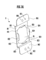
- Fig. 3A is a detail drawing showing the retention member 8.
- Fig. 3B is a view as seen in the direction of the arrows A-A in Fig. 1, showing this retention member 8 in the state when it is installed to the lamp cover 3.
- the retention member 8 is formed by bending a single plate.
- Aluminum plate may be used, for example, as the material for this retention member 8.
- the various portions of this retention member 8 will be explained.
- a cover glass holding portion 80 is an indented portion which holds the cover glass 7, and it constitutes a holding portion which fixes the cover glass 7 by pressing it against the shield member 2.
- An aperture 81 is opened in the member 8 for allowing the light from the lamp 13 to pass through, and has a shape which matches the shape of the cover glass 7.
- Projecting flange portions 821 ⁇ 824 are projecting flange portions which are made by bending projecting portions provided as extending from the sides of the aperture 81 towards the side of fitting portions 861 and 862 which will be explained hereinafter. When the retention member 8 is fitted, these projecting flange portions 821 - 824 face and confront the four sides of the cover glass 7, and cover these four sides at the same time.
- the region which is surrounded within these projecting flange portions 821 ⁇ 824 is formed to be wider than the width of the cover glass 7, in consideration of the fact that the cover glass 7 expands due to the heat of the lamp 13. Furthermore, the region which is surrounded by the projecting portions 261 ⁇ 264 (refer to Fig. 3B is formed to be yet larger than the region which is surrounded on the inside of the projecting flange portions 821 ⁇ 824. Since, because of this, when the projector 1 is dropped, not the corners of the cover glass 7, but rather its edges strike against the projecting portions 261 ⁇ 264, accordingly the corners of the cover glass 7 do not suffer damage at this time.
- Radiused portions 831 ⁇ 834 are circular arcs which are provided at the four corners of the aperture 81. These radiused portions 831 ⁇ 834 are formed so that, when the retention member is positioned so as to cover over the cover glass 8, the portions on the insides of these radiused portions 831 ⁇ 834 contact the cover glass 7 at positions inwards from the external edge of the cover glass 7. Due to this, it is possible for the corners of the cover glass 7 to be squeezed by the retention member 8 and the insides of the radiused portion 831 ⁇ 834, so that it is possible for the retention member 8 to press the cover glass 7 against the shield member 2.
- radiused portions 831 ⁇ 834 may be replaced by chamfering. If this is done, it is still possible to arrange for a portion of the aperture 81 to be formed so as to be inwards of the external circumference of the cover glass 7. Accordingly, the retention member 8 can press the four corners of the cover glass 7 against the shield member 2 with these chamfered portions, so that the retention member 8 can retain the cover glass 7.
- Curved portions 851 and 852 are bent portions which connect from the cover glass holding portion 80, i.e. the central portion of the retention member 8, to both flanks, and they are folded to and fro in cranked shapes.
- the fitting portion 861 is a portion which continues on from the curved portion 851, and which is fixed to the shield member 2.
- the fitting portion 862 is a portion which continues on from the curved portion 852, and which fixes the retention member 8 to the shield member 2.
- holes for position determination 871 and 872 are holes for position determination when fitting the retention member 8 to the shield member 2.
- fitting holes 881 and 882 are holes for fixing the retention member 8 to the shield member 2 with screws.
- the cover glass 7 is mounted within the projecting portions 261 - 264 of the shield member 2. By mounting it in this manner, it is possible to perform position determination for the cover glass 7 in a simple and easy manner.
- the retention member 8 is fitted to the shield member 2 from over the cover glass 7.
- the indentation of the cover glass holding portion 80 matches the cover glass 7.
- the hole for position determination 871 of the retention member 8 goes over the position determination pin 271 of the shield member 2, while the hole for position determination 872 of the retention member 8 goes over the position determination pin 272 of the shield member 2.
- the retention member 8 covers the cover glass 7, and, along with the fitting holes 281 and 282 overlapping the holes 881 and 882 respectively, also the projecting flange portions 821 ⁇ 824 of the retention member 8 simultaneously come to be disposed around the cover glass 7.
- the projecting flange portions 821 - 824 of the retention member 8 are positioned apart at gaps which are larger than the width of the cover glass 7. Accordingly, although the retention member 8 does not directly retain the corners and the sides of the cover glass 7, if the projector 1 is dropped, then the projecting flange portions 821 ⁇ 824 of the retention member 8 retain all of the four sides of the cover glass 7.
- the region which is surrounded at two of its corners by the projecting portions 261 ⁇ 264 of the shield member 2 is made to be yet larger than the region which is surrounded by the projecting flange portions 821 ⁇ 824 which surround the cover glass on its four sides, accordingly, when the projector 1 is dropped, not the corners of the cover glass 7, but rather one of the edges of the cover glass 7 and one of the projecting portions 261 ⁇ 264 come into mutual contact. Due to this, when the projector 1 is dropped, the shock which is applied to the cover glass 7 is spread. It has been actually verified, according to tests performed by the present inventor, that, when the projector 1 is dropped from the height at which it is typically carried by a person, no damage is caused to the four edges or to the four corners of the cover glass 7.
- the region which is surrounded at two of its corners by the projecting portions 261 ⁇ 264 of the shield member 2 is made to be larger than the region which is surrounded by the projecting flange portions 821 ⁇ 824 which surround the cover glass on its four sides, even if these regions are made to be of the same size, there is no change with regard to the beneficial effect of the projecting flange portions 821 ⁇ 824 being able to support the edges of the cover glass 7 when the projector is dropped.
- the retention member 8 is made from a thin plate or the like, so that the projecting flange portions 821 ⁇ 824 are endowed with elasticity, then since, as described above, when the projector is dropped, shock imparted to the four sides of the cover glass 7 is absorbed, accordingly it is possible to eliminate damage to the corners of the cover glass 7 to yet a further level.
- the cover glass 7 had four corners, it would also be acceptable for it to have some other polygonal shape, for example a triangle.
- the projecting flange portions 821 ⁇ 824 retained the cover glass 7 on all four of its sides, it would also be acceptable for them only to hold it on some of its sides. The same is the case if the cover glass 7 is some polygon having other than four sides.
- the beneficial effect described above of dispersing the shock when the projector is dropped is higher, the wider is the area over which the projecting flange portions contact the cover glass 7.
Landscapes
- Physics & Mathematics (AREA)
- General Physics & Mathematics (AREA)
- Projection Apparatus (AREA)
- Non-Portable Lighting Devices Or Systems Thereof (AREA)
Abstract
A projector (1) includes a lamp unit (10). This lamp unit (10) includes a lamp (13) which emits light, a shield member (2) in which an opening portion (25) is formed which allows light emitted by the lamp (13) to radiate to the exterior, a cover glass (7) fitted to the opening portion (25), and a retention member (8) which retains the cover glass (7) by squeezing it against the shield member (2). The retention member (8) is provided with projecting flange portions (821-824) which press against the four edges of the cover glass (7).
Description
- In the prior art, projectors have been implemented which project pictures upon screens in front of their projection lenses using lamp units. Such a lamp unit is covered with a lamp cover having an opening portion in front of the lamp unit. Such a lamp cover emits light from this opening portion, while leakage of light from the parts thereof other than this opening portion is prevented. To the opening portion, there is provided a cover glass which is transparent to light of a predetermined range of wavelengths, and which intercepts ultraviolet rays. Due to this, the cover glass prevents ultraviolet rays included in the light from the light source lamp from getting out to the exterior. Furthermore, in order to prevent these ultraviolet rays from passing through the lamp cover and leaking, there is a tendency to manufacture the material of the lamp cover not from plastic resin, but from aluminum alloy.
- Moreover, since the vicinity of the lamp attains an extremely high temperature, the cover glass can easily fail, and can easily become distorted. As a countermeasure against this, for example as described in
Japanese Laid-Open Patent Publication Heisei 7-63966 Japanese Laid-Open Patent Publication Heisei 7-63966 - However, if the structure described in
Japanese Laid-Open Patent Publication Heisei 7-63966 - Accordingly, in order to make the assembly of the cover glass easy, it is arranged to provide projections for position determination which set the position of two of the corners of the cover glass at the opening portion where the light of the lamp unit is emitted.
- If the lamp cover, including its opening portion, is made from aluminum alloy, then, since this aluminum alloy is hard, if as previously described the lamp cover is dropped from the typical height at which it is carried by a person, the retention portion for the cover glass cannot sufficiently alleviate the shock, and there has been the problem that the corners of the cover glass may be damaged.
- Accordingly, the object of the present invention is to provide a projector which has a simple structure and which is easy to assemble, and which is able to prevent damage to the cover glass even if the main body of the projector is dropped from the typical height at which it is carried by a person.
- The projector of the present invention projects a picture upon a screen using light emitted from a lamp unit.
- The lamp unit includes a lamp, a shield member, a cover glass, and a retention member.
- The lamp is a light source for projecting a picture upon a screen.
- The shield member is formed with an opening portion which allows light emitted by the lamp to be radiated to the exterior. The cover glass is fitted to the opening portion of the shield member.
- The retention member retains the cover glass by squeezing it against the shield member.
- And the retention member has a plurality of projecting flange portions, each of which is provided so as to confront one of a plurality of edges of said cover glass.
-
- Fig. 1 is a perspective view showing the general structure of a projector according to an embodiment of the present invention;
- Fig. 2A and Fig. 2B are details drawing showing a shield member of this embodiment; and
- Fig. 3A and Fig. 3B are details drawing showing a retention member which, in this embodiment, is attached to a lamp cover, and a Figure showing this retention member in the state in which it is installed to the lamp cover.
- Fig. 1 is a perspective view showing the general structure of the interior of a projector. The structure of this projector 1 will now be explained in the following. A
lamp unit 10 comprises alamp cover 3 which includes ashield member 2, and alamp 13 inside thelamp cover 3. Thislamp 13 emits light for projecting a picture. Thelamp cover 3 is a cover provided over the outside of thelamp 13. And theshield member 2 is a member which shields light emitted by thelamp 13, and which is provided with an opening portion through which the light emitted by thelamp 13 is radiated towards a picture projection unit 11. The picture projection unit 11 comprises a picture display device such as a DMD (Digital Mirror Device) or the like and a color wheel (neither of which is shown in the Figures) and aprojection lens 12, and projects a picture upon a screen using the light which is outputted from thelamp unit 10.Main fans chassis 9. A portion of this air which is blown is conducted from anintake aperture 14 into thelamp unit 10, and is discharged from anexhaust aperture 15. The temperature of thelamp 13, which generates a lot of heat, is lowered by the flow of air thus being blown through thelamp unit 10. Thechassis 9 is a box which houses the various components of the projector 1. - The structure of the
shield member 2 will now be described in detail using Fig. 2A and Fig. 2B. Fig. 2A is a plan view as seen from the top of the projector 1. And Fig. 2B is a view as seen from the direction A-A in Fig. 1. It should be understood that, in Fig. 2A and Fig. 2B, the arrangement of thelamp cover 3, thelamp 13, theexhaust aperture 15, and thecover glass 7 is shown by the double dotted broken lines. - In order to prevent ultraviolet rays passing through the
shield member 2, theshield member 2 is made from aluminum alloy. A flange 20 of theshield member 2 is a flange portion for attaching theshield member 2 to thelamp cover 3 so as to cover thelamp 13. - A
body 21 is formed as an approximately octagonal tubular unit with an internal cavity. Thisbody 21 has aflat fitting surface 211 on its side opposite to the flange 20. Anopening portion 25 is opened in thisfitting surface 211. - Fitting
portions shield member 2 side of thelamp unit 10, and on their insides they are provided with holes for passing bolts. - The
opening portion 25 is a hole opened in thefitting surface 211, and is formed to be smaller than a cover glass 7 (described hereinafter) which is fitted thereto. Due to this, it is possible to fit thecover glass 7 by sandwiching it between theopening portion 25 and aretention member 8 which will be described hereinafter (refer to Fig. 3A). Theopening portion 25 allows light from thelamp 13 to be emitted towards the picture projection unit 11. Furthermore thecover glass 7, which is made as a four cornered plate shaped piece of glass as shown by the double dotted broken lines, is fitted to theopening portion 25. - Projecting
portions 261 ∼ 264 are provided upon thefitting surface 211, located at opposite ends of a diagonal of the four corneredcover glass 7 so as to receive and surround each of the two corners at these ends of the diagonal, and are formed integrally with theshield member 2. When assembling thecover glass 7, these projectingportions 261 ∼ 264 determine the position of the corners of the cover glass upon this diagonal line. Due to this, it becomes easy to fit thecover glass 7 to thelamp cover 2. - It should be understood that these projecting
portions 261 ~264 may not be formed integrally with theshield member 2; they may be attached thereto. For example, it would also be acceptable for them to be fixed by welding, screw fixing, or the like. - Position determination pins 271 and 272 are pins for position determination when fixing the
retention member 8 which will be described hereinafter (refer to Fig. 3A and Fig. 3B). These position determination pins 271 and 272 may be formed integrally with thebody 21, or may be formed by opening holes in thebody 21 and driving position determination pins thereinto. And fittingholes retention member 8 with bolts. It should be understood that thisretention member 8 covers from above over thecover glass 7 which is fitted to thefitting surface 211, and is fixed by bolts in thefitting holes - The structure of the
retention member 8, and the method of fitting thecover glass 7 and theretention member 8 will now be explained using Fig. 3A and Fig. 3B. Fig. 3A is a detail drawing showing theretention member 8. And Fig. 3B is a view as seen in the direction of the arrows A-A in Fig. 1, showing thisretention member 8 in the state when it is installed to thelamp cover 3. - As shown in Fig. 3A, the
retention member 8 is formed by bending a single plate. Aluminum plate may be used, for example, as the material for thisretention member 8. In the following, the various portions of thisretention member 8 will be explained. - A cover
glass holding portion 80 is an indented portion which holds thecover glass 7, and it constitutes a holding portion which fixes thecover glass 7 by pressing it against theshield member 2. Anaperture 81 is opened in themember 8 for allowing the light from thelamp 13 to pass through, and has a shape which matches the shape of thecover glass 7. Projectingflange portions 821 ∼ 824 are projecting flange portions which are made by bending projecting portions provided as extending from the sides of theaperture 81 towards the side offitting portions retention member 8 is fitted, these projecting flange portions 821 - 824 face and confront the four sides of thecover glass 7, and cover these four sides at the same time. The region which is surrounded within these projectingflange portions 821 ~ 824 is formed to be wider than the width of thecover glass 7, in consideration of the fact that thecover glass 7 expands due to the heat of thelamp 13. Furthermore, the region which is surrounded by the projectingportions 261 ∼ 264 (refer to Fig. 3B is formed to be yet larger than the region which is surrounded on the inside of the projectingflange portions 821~ 824. Since, because of this, when the projector 1 is dropped, not the corners of thecover glass 7, but rather its edges strike against the projectingportions 261 ∼ 264, accordingly the corners of thecover glass 7 do not suffer damage at this time. -
Radiused portions 831 ∼ 834 are circular arcs which are provided at the four corners of theaperture 81. Theseradiused portions 831 ∼ 834 are formed so that, when the retention member is positioned so as to cover over thecover glass 8, the portions on the insides of theseradiused portions 831 ∼ 834 contact thecover glass 7 at positions inwards from the external edge of thecover glass 7. Due to this, it is possible for the corners of thecover glass 7 to be squeezed by theretention member 8 and the insides of the radiusedportion 831 ∼ 834, so that it is possible for theretention member 8 to press thecover glass 7 against theshield member 2. - It should be understood that these
radiused portions 831 ~ 834 may be replaced by chamfering. If this is done, it is still possible to arrange for a portion of theaperture 81 to be formed so as to be inwards of the external circumference of thecover glass 7. Accordingly, theretention member 8 can press the four corners of thecover glass 7 against theshield member 2 with these chamfered portions, so that theretention member 8 can retain thecover glass 7. -
Curved portions glass holding portion 80, i.e. the central portion of theretention member 8, to both flanks, and they are folded to and fro in cranked shapes. - The
fitting portion 861 is a portion which continues on from thecurved portion 851, and which is fixed to theshield member 2. And thefitting portion 862 is a portion which continues on from thecurved portion 852, and which fixes theretention member 8 to theshield member 2. And holes forposition determination retention member 8 to theshield member 2. Moreover,fitting holes retention member 8 to theshield member 2 with screws. - Now, using Fig. 3B, the method for fitting the
cover glass 7 and theretention member 8 to theshield member 2 will be explained. - First, the
cover glass 7 is mounted within the projecting portions 261 - 264 of theshield member 2. By mounting it in this manner, it is possible to perform position determination for thecover glass 7 in a simple and easy manner. - Next, the
retention member 8 is fitted to theshield member 2 from over thecover glass 7. At this time, the indentation of the coverglass holding portion 80 matches thecover glass 7. Furthermore, the hole forposition determination 871 of theretention member 8 goes over theposition determination pin 271 of theshield member 2, while the hole forposition determination 872 of theretention member 8 goes over theposition determination pin 272 of theshield member 2. When theretention member 8 is fitted in this manner, theretention member 8 covers thecover glass 7, and, along with thefitting holes holes flange portions 821 ∼ 824 of theretention member 8 simultaneously come to be disposed around thecover glass 7. - Next, screws are inserted into the
fitting holes holes shield member 2. When theretention member 8 has been fitted to theshield member 2 from over thecover glass 7 in this manner, thecover glass 7 is thereby retained. With regard to retention of thecover glass 7 in the direction perpendicular to its surface, this is performed by the portions at the exteriors of the radiused portions 831 - 834 of theretention member 8 pressing the four corners of thecover glass 7 against theshield member 2. Furthermore, with regard to retention of thecover glass 7 in the direction parallel to its surface, this is performed by the frictional force due to theretention member 8 pressing thecover glass 7 against theshield member 2. - As previously described, in consideration of thermal expansion of the
cover glass 7, the projecting flange portions 821 - 824 of theretention member 8 are positioned apart at gaps which are larger than the width of thecover glass 7. Accordingly, although theretention member 8 does not directly retain the corners and the sides of thecover glass 7, if the projector 1 is dropped, then the projectingflange portions 821 ~ 824 of theretention member 8 retain all of the four sides of thecover glass 7. - Furthermore, since the region which is surrounded at two of its corners by the projecting
portions 261 ∼ 264 of theshield member 2 is made to be yet larger than the region which is surrounded by the projectingflange portions 821 ∼ 824 which surround the cover glass on its four sides, accordingly, when the projector 1 is dropped, not the corners of thecover glass 7, but rather one of the edges of thecover glass 7 and one of the projectingportions 261 ∼ 264 come into mutual contact. Due to this, when the projector 1 is dropped, the shock which is applied to thecover glass 7 is spread. It has been actually verified, according to tests performed by the present inventor, that, when the projector 1 is dropped from the height at which it is typically carried by a person, no damage is caused to the four edges or to the four corners of thecover glass 7. - It should be understood that although, in the embodiment described above, the region which is surrounded at two of its corners by the projecting
portions 261 ∼ 264 of theshield member 2 is made to be larger than the region which is surrounded by the projectingflange portions 821 ∼ 824 which surround the cover glass on its four sides, even if these regions are made to be of the same size, there is no change with regard to the beneficial effect of the projectingflange portions 821 ∼ 824 being able to support the edges of thecover glass 7 when the projector is dropped. - Furthermore since, in the process of fitting the
cover glass 7, it is only necessary to fit thecover glass 7 within the insides of the projectingportions 261 ∼ 264 of thecover glass 7, and to fit theretention member 8 over the position determination pins 271 and 272, with bolts being fixed into thefitting holes Japanese Laid-Open Patent Publication Heisei 7-63966 - According to the above description, with the projector 1 of this embodiment, while employing a structure which can be simply and easily assembled and moreover which uses a
simple retention member 8, it is possible to prevent damage to thecover glass 7 if the projector main body is dropped. - It should be understood that, if the
retention member 8 is made from a thin plate or the like, so that the projectingflange portions 821 ∼ 824 are endowed with elasticity, then since, as described above, when the projector is dropped, shock imparted to the four sides of thecover glass 7 is absorbed, accordingly it is possible to eliminate damage to the corners of thecover glass 7 to yet a further level. If this structure is employed, then it is desirable to make the spaces between the projectingportions 261 ∼ 264 bigger than the region over which thecover glass 7 is capable of shifting due to the elasticity of the projectingflange portions 821 ∼ 824, since thereby it is ensured that, when the projector 1 is dropped, the projectingportions 261 ∼ 264 which retain the corners of thecover glass 7 do not come into contact with them. - Furthermore, it would also be acceptable to provide a structure in which no such portions as the projecting
portions 261 ∼ 264 were provided to theshield member 2. In this case as well, if the projector 1 is dropped from a height such as that at which it is typically carried by a person, the edges of thecover glass 7 are retained by the projectingflange portions 821 ~ 824 of themember 8, so that no damage to the corners of thecover glass 7 occurs. - Furthermore although, in the above explanation, the case was explained in which the
cover glass 7 had four corners, it would also be acceptable for it to have some other polygonal shape, for example a triangle. Moreover although, in the above explanation, the projectingflange portions 821 ∼ 824 retained thecover glass 7 on all four of its sides, it would also be acceptable for them only to hold it on some of its sides. The same is the case if thecover glass 7 is some polygon having other than four sides. However, the beneficial effect described above of dispersing the shock when the projector is dropped is higher, the wider is the area over which the projecting flange portions contact thecover glass 7.
Claims (4)
- A projector (1) which projects a picture upon a screen using light emitted from a lamp unit (10), wherein said lamp unit (10) comprises:a lamp (13) which constitutes a light source;a shield member (2) in which an opening portion (25) is formed which allows light emitted by said lamp (13) to be radiated to the exterior;a cover glass (7) which is fitted to said opening portion (25) of said shield member (2); anda retention member (8) which retains said cover glass (7) by squeezing it against said shield member (2),wherein said retention member (8) comprises a plurality of projecting flange portions (821-824), each of which is provided so as to confront one of a plurality of edges of said cover glass (7).
- A projector (1) as described in Claim 1, wherein said shield member (2) comprises projecting portions (261-264) which surround each of two corners of said cover glass (7) which are not mutually adjacent.
- A projector (1) as described in Claim 2, wherein said projecting portions (261-264) are formed so that the region surrounded by said projecting portions (261-264) is larger than the region surrounded by said projecting flange portions (821-824).
- A projector (1) as described in Claim 1, wherein said retention member (8) is formed by bending a single plate.
Applications Claiming Priority (1)
| Application Number | Priority Date | Filing Date | Title |
|---|---|---|---|
| JP2006098992A JP2007272039A (en) | 2006-03-31 | 2006-03-31 | projector |
Publications (1)
| Publication Number | Publication Date |
|---|---|
| EP1840643A1 true EP1840643A1 (en) | 2007-10-03 |
Family
ID=38268895
Family Applications (1)
| Application Number | Title | Priority Date | Filing Date |
|---|---|---|---|
| EP07006328A Withdrawn EP1840643A1 (en) | 2006-03-31 | 2007-03-27 | Projector |
Country Status (4)
| Country | Link |
|---|---|
| US (1) | US20070229764A1 (en) |
| EP (1) | EP1840643A1 (en) |
| JP (1) | JP2007272039A (en) |
| CN (1) | CN101046610A (en) |
Families Citing this family (1)
| Publication number | Priority date | Publication date | Assignee | Title |
|---|---|---|---|---|
| WO2015111543A1 (en) * | 2014-01-22 | 2015-07-30 | 株式会社小糸製作所 | Vehicle lamp |
Citations (4)
| Publication number | Priority date | Publication date | Assignee | Title |
|---|---|---|---|---|
| JPH0763966A (en) * | 1993-08-24 | 1995-03-10 | Nec Corp | Filter holding mechanism |
| US20050219480A1 (en) * | 2004-04-06 | 2005-10-06 | Funai Electric Co., Ltd. | Projector |
| TWM283206U (en) * | 2005-04-22 | 2005-12-11 | Coretronic Corp | Fixing structure |
| US20060001844A1 (en) * | 2004-06-30 | 2006-01-05 | Mitsuharu Fukuda | Light source apparatus and an image display apparatus |
Family Cites Families (5)
| Publication number | Priority date | Publication date | Assignee | Title |
|---|---|---|---|---|
| JPH01254440A (en) * | 1988-04-05 | 1989-10-11 | Koito Mfg Co Ltd | Head light for automobile |
| JPH11133507A (en) * | 1997-10-27 | 1999-05-21 | Canon Inc | Illumination device and projector device provided with the illumination device |
| US6461025B1 (en) * | 2000-12-14 | 2002-10-08 | Infocus Corp | Lamp assembly with snap fit components |
| US6695461B2 (en) * | 2000-12-25 | 2004-02-24 | Seiko Epson Corporation | Lamp unit, projector, and fixing method of light source lamp and reflector |
| WO2002097529A1 (en) * | 2001-05-28 | 2002-12-05 | Seiko Epson Corporation | Projector |
-
2006
- 2006-03-31 JP JP2006098992A patent/JP2007272039A/en active Pending
-
2007
- 2007-03-27 EP EP07006328A patent/EP1840643A1/en not_active Withdrawn
- 2007-03-28 US US11/727,779 patent/US20070229764A1/en not_active Abandoned
- 2007-04-02 CN CNA2007100921196A patent/CN101046610A/en active Pending
Patent Citations (4)
| Publication number | Priority date | Publication date | Assignee | Title |
|---|---|---|---|---|
| JPH0763966A (en) * | 1993-08-24 | 1995-03-10 | Nec Corp | Filter holding mechanism |
| US20050219480A1 (en) * | 2004-04-06 | 2005-10-06 | Funai Electric Co., Ltd. | Projector |
| US20060001844A1 (en) * | 2004-06-30 | 2006-01-05 | Mitsuharu Fukuda | Light source apparatus and an image display apparatus |
| TWM283206U (en) * | 2005-04-22 | 2005-12-11 | Coretronic Corp | Fixing structure |
Also Published As
| Publication number | Publication date |
|---|---|
| JP2007272039A (en) | 2007-10-18 |
| US20070229764A1 (en) | 2007-10-04 |
| CN101046610A (en) | 2007-10-03 |
Similar Documents
| Publication | Publication Date | Title |
|---|---|---|
| JP4901595B2 (en) | Projection display | |
| US7866828B2 (en) | Projection type image display apparatus | |
| KR100693349B1 (en) | DMD assembly for optical projection system | |
| EP1835336A1 (en) | Projection apparatus | |
| US20070216871A1 (en) | Projector | |
| JPWO2006100857A1 (en) | Lighting device | |
| US11256164B2 (en) | Optical element and projection device using the same | |
| US7364308B2 (en) | Projector apparatus | |
| JP4243269B2 (en) | Projector device | |
| JP2006322981A (en) | Projection optical system unit and projection type image display device using the same | |
| US6709112B2 (en) | Light source device and projection type display capable of enclosing fragment herein in case of burst of discharge lamp during lighting | |
| US9703184B2 (en) | Dimmer and projector | |
| CN100594422C (en) | Light source device and projection-type image display device | |
| JP2008098086A (en) | Light source lamp unit | |
| KR100621184B1 (en) | Optical engine and image projection apparatus including the same | |
| CN209215848U (en) | projector | |
| JP2006285044A (en) | Projection-type image display apparatus | |
| US20070229764A1 (en) | Projector | |
| JP3557165B2 (en) | Light source device and projection type video display device having the same | |
| JP4225991B2 (en) | Projector device | |
| JP4540573B2 (en) | Projector device | |
| JP2014174273A (en) | Light-shielding member of light tunnel and image display device | |
| JP3092510U (en) | Light tunnel protection structure of image display projector and image display projector | |
| US9772545B2 (en) | Light control unit, projector, and method of manufacturing light control unit | |
| US12379651B2 (en) | Projection lens module |
Legal Events
| Date | Code | Title | Description |
|---|---|---|---|
| PUAI | Public reference made under article 153(3) epc to a published international application that has entered the european phase |
Free format text: ORIGINAL CODE: 0009012 |
|
| AK | Designated contracting states |
Kind code of ref document: A1 Designated state(s): AT BE BG CH CY CZ DE DK EE ES FI FR GB GR HU IE IS IT LI LT LU LV MC MT NL PL PT RO SE SI SK TR |
|
| AX | Request for extension of the european patent |
Extension state: AL BA HR MK YU |
|
| 17P | Request for examination filed |
Effective date: 20080403 |
|
| AKX | Designation fees paid |
Designated state(s): DE FR GB |
|
| STAA | Information on the status of an ep patent application or granted ep patent |
Free format text: STATUS: THE APPLICATION HAS BEEN WITHDRAWN |
|
| 18W | Application withdrawn |
Effective date: 20141128 |