EP1840362A1 - Sleeve and cylinder head cover - Google Patents
Sleeve and cylinder head cover Download PDFInfo
- Publication number
- EP1840362A1 EP1840362A1 EP06711711A EP06711711A EP1840362A1 EP 1840362 A1 EP1840362 A1 EP 1840362A1 EP 06711711 A EP06711711 A EP 06711711A EP 06711711 A EP06711711 A EP 06711711A EP 1840362 A1 EP1840362 A1 EP 1840362A1
- Authority
- EP
- European Patent Office
- Prior art keywords
- sleeve
- oil
- main body
- rubber
- cylinder head
- Prior art date
- Legal status (The legal status is an assumption and is not a legal conclusion. Google has not performed a legal analysis and makes no representation as to the accuracy of the status listed.)
- Granted
Links
Images


Classifications
-
- F—MECHANICAL ENGINEERING; LIGHTING; HEATING; WEAPONS; BLASTING
- F01—MACHINES OR ENGINES IN GENERAL; ENGINE PLANTS IN GENERAL; STEAM ENGINES
- F01L—CYCLICALLY OPERATING VALVES FOR MACHINES OR ENGINES
- F01L1/00—Valve-gear or valve arrangements, e.g. lift-valve gear
- F01L1/34—Valve-gear or valve arrangements, e.g. lift-valve gear characterised by the provision of means for changing the timing of the valves without changing the duration of opening and without affecting the magnitude of the valve lift
-
- F—MECHANICAL ENGINEERING; LIGHTING; HEATING; WEAPONS; BLASTING
- F01—MACHINES OR ENGINES IN GENERAL; ENGINE PLANTS IN GENERAL; STEAM ENGINES
- F01L—CYCLICALLY OPERATING VALVES FOR MACHINES OR ENGINES
- F01L1/00—Valve-gear or valve arrangements, e.g. lift-valve gear
- F01L1/34—Valve-gear or valve arrangements, e.g. lift-valve gear characterised by the provision of means for changing the timing of the valves without changing the duration of opening and without affecting the magnitude of the valve lift
- F01L1/344—Valve-gear or valve arrangements, e.g. lift-valve gear characterised by the provision of means for changing the timing of the valves without changing the duration of opening and without affecting the magnitude of the valve lift changing the angular relationship between crankshaft and camshaft, e.g. using helicoidal gear
-
- F—MECHANICAL ENGINEERING; LIGHTING; HEATING; WEAPONS; BLASTING
- F02—COMBUSTION ENGINES; HOT-GAS OR COMBUSTION-PRODUCT ENGINE PLANTS
- F02F—CYLINDERS, PISTONS OR CASINGS, FOR COMBUSTION ENGINES; ARRANGEMENTS OF SEALINGS IN COMBUSTION ENGINES
- F02F7/00—Casings, e.g. crankcases
- F02F7/006—Camshaft or pushrod housings
-
- F—MECHANICAL ENGINEERING; LIGHTING; HEATING; WEAPONS; BLASTING
- F16—ENGINEERING ELEMENTS AND UNITS; GENERAL MEASURES FOR PRODUCING AND MAINTAINING EFFECTIVE FUNCTIONING OF MACHINES OR INSTALLATIONS; THERMAL INSULATION IN GENERAL
- F16J—PISTONS; CYLINDERS; SEALINGS
- F16J15/00—Sealings
- F16J15/02—Sealings between relatively-stationary surfaces
- F16J15/06—Sealings between relatively-stationary surfaces with solid packing compressed between sealing surfaces
- F16J15/10—Sealings between relatively-stationary surfaces with solid packing compressed between sealing surfaces with non-metallic packing
- F16J15/12—Sealings between relatively-stationary surfaces with solid packing compressed between sealing surfaces with non-metallic packing with metal reinforcement or covering
- F16J15/121—Sealings between relatively-stationary surfaces with solid packing compressed between sealing surfaces with non-metallic packing with metal reinforcement or covering with metal reinforcement
- F16J15/122—Sealings between relatively-stationary surfaces with solid packing compressed between sealing surfaces with non-metallic packing with metal reinforcement or covering with metal reinforcement generally parallel to the surfaces
-
- F—MECHANICAL ENGINEERING; LIGHTING; HEATING; WEAPONS; BLASTING
- F16—ENGINEERING ELEMENTS AND UNITS; GENERAL MEASURES FOR PRODUCING AND MAINTAINING EFFECTIVE FUNCTIONING OF MACHINES OR INSTALLATIONS; THERMAL INSULATION IN GENERAL
- F16K—VALVES; TAPS; COCKS; ACTUATING-FLOATS; DEVICES FOR VENTING OR AERATING
- F16K11/00—Multiple-way valves, e.g. mixing valves; Pipe fittings incorporating such valves
- F16K11/02—Multiple-way valves, e.g. mixing valves; Pipe fittings incorporating such valves with all movable sealing faces moving as one unit
- F16K11/06—Multiple-way valves, e.g. mixing valves; Pipe fittings incorporating such valves with all movable sealing faces moving as one unit comprising only sliding valves, i.e. sliding closure elements
- F16K11/065—Multiple-way valves, e.g. mixing valves; Pipe fittings incorporating such valves with all movable sealing faces moving as one unit comprising only sliding valves, i.e. sliding closure elements with linearly sliding closure members
- F16K11/07—Multiple-way valves, e.g. mixing valves; Pipe fittings incorporating such valves with all movable sealing faces moving as one unit comprising only sliding valves, i.e. sliding closure elements with linearly sliding closure members with cylindrical slides
- F16K11/0712—Multiple-way valves, e.g. mixing valves; Pipe fittings incorporating such valves with all movable sealing faces moving as one unit comprising only sliding valves, i.e. sliding closure elements with linearly sliding closure members with cylindrical slides comprising particular spool-valve sealing means
-
- F—MECHANICAL ENGINEERING; LIGHTING; HEATING; WEAPONS; BLASTING
- F01—MACHINES OR ENGINES IN GENERAL; ENGINE PLANTS IN GENERAL; STEAM ENGINES
- F01L—CYCLICALLY OPERATING VALVES FOR MACHINES OR ENGINES
- F01L1/00—Valve-gear or valve arrangements, e.g. lift-valve gear
- F01L1/34—Valve-gear or valve arrangements, e.g. lift-valve gear characterised by the provision of means for changing the timing of the valves without changing the duration of opening and without affecting the magnitude of the valve lift
- F01L1/344—Valve-gear or valve arrangements, e.g. lift-valve gear characterised by the provision of means for changing the timing of the valves without changing the duration of opening and without affecting the magnitude of the valve lift changing the angular relationship between crankshaft and camshaft, e.g. using helicoidal gear
- F01L1/3442—Valve-gear or valve arrangements, e.g. lift-valve gear characterised by the provision of means for changing the timing of the valves without changing the duration of opening and without affecting the magnitude of the valve lift changing the angular relationship between crankshaft and camshaft, e.g. using helicoidal gear using hydraulic chambers with variable volume to transmit the rotating force
- F01L2001/34423—Details relating to the hydraulic feeding circuit
- F01L2001/34426—Oil control valves
-
- F—MECHANICAL ENGINEERING; LIGHTING; HEATING; WEAPONS; BLASTING
- F01—MACHINES OR ENGINES IN GENERAL; ENGINE PLANTS IN GENERAL; STEAM ENGINES
- F01L—CYCLICALLY OPERATING VALVES FOR MACHINES OR ENGINES
- F01L1/00—Valve-gear or valve arrangements, e.g. lift-valve gear
- F01L1/34—Valve-gear or valve arrangements, e.g. lift-valve gear characterised by the provision of means for changing the timing of the valves without changing the duration of opening and without affecting the magnitude of the valve lift
- F01L1/344—Valve-gear or valve arrangements, e.g. lift-valve gear characterised by the provision of means for changing the timing of the valves without changing the duration of opening and without affecting the magnitude of the valve lift changing the angular relationship between crankshaft and camshaft, e.g. using helicoidal gear
- F01L1/3442—Valve-gear or valve arrangements, e.g. lift-valve gear characterised by the provision of means for changing the timing of the valves without changing the duration of opening and without affecting the magnitude of the valve lift changing the angular relationship between crankshaft and camshaft, e.g. using helicoidal gear using hydraulic chambers with variable volume to transmit the rotating force
- F01L2001/34423—Details relating to the hydraulic feeding circuit
- F01L2001/34426—Oil control valves
- F01L2001/3443—Solenoid driven oil control valves
-
- F—MECHANICAL ENGINEERING; LIGHTING; HEATING; WEAPONS; BLASTING
- F01—MACHINES OR ENGINES IN GENERAL; ENGINE PLANTS IN GENERAL; STEAM ENGINES
- F01L—CYCLICALLY OPERATING VALVES FOR MACHINES OR ENGINES
- F01L1/00—Valve-gear or valve arrangements, e.g. lift-valve gear
- F01L1/34—Valve-gear or valve arrangements, e.g. lift-valve gear characterised by the provision of means for changing the timing of the valves without changing the duration of opening and without affecting the magnitude of the valve lift
- F01L1/344—Valve-gear or valve arrangements, e.g. lift-valve gear characterised by the provision of means for changing the timing of the valves without changing the duration of opening and without affecting the magnitude of the valve lift changing the angular relationship between crankshaft and camshaft, e.g. using helicoidal gear
- F01L1/3442—Valve-gear or valve arrangements, e.g. lift-valve gear characterised by the provision of means for changing the timing of the valves without changing the duration of opening and without affecting the magnitude of the valve lift changing the angular relationship between crankshaft and camshaft, e.g. using helicoidal gear using hydraulic chambers with variable volume to transmit the rotating force
- F01L2001/34423—Details relating to the hydraulic feeding circuit
- F01L2001/34426—Oil control valves
- F01L2001/34433—Location oil control valves
-
- F—MECHANICAL ENGINEERING; LIGHTING; HEATING; WEAPONS; BLASTING
- F01—MACHINES OR ENGINES IN GENERAL; ENGINE PLANTS IN GENERAL; STEAM ENGINES
- F01L—CYCLICALLY OPERATING VALVES FOR MACHINES OR ENGINES
- F01L2301/00—Using particular materials
Definitions
- the present invention relates to a sleeve allowing insertion of an oil control valve (OCV) and being inserted, when used, to an installation hole provided in a cylinder head cover.
- OCV oil control valve
- the present invention also relates to a cylinder head cover to which the sleeve is installed.
- a hydraulically operated variable valve actuation mechanism is provided in a timing sprocket, a timing pulley or the like of an internal combustion engine
- a hydraulic oil supply and drain oil passage connecting an oil control valve with the variable valve actuation mechanism is generally provided so as to pass through a camshaft.
- the oil control valve is installed to the cylinder head cover, and the hydraulic oil is supplied and drained via the oil passage within the cam cap and the camshaft by the oil control valve (for example, refer to patent document 1).
- Patent Document 1 Japanese Patent Publication No. 3525709
- the present invention provides the following sleeve.
- the sleeve allows insertion of the oil control valve, and being inserted, when used, to an installation hole provided in the cylinder head cover.
- the sleeve is provided with a tubular sleeve main body, an oil hole, and a rubber-like elastic body layer.
- the sleeve main body has an outer surface having a shape corresponding to a shape of a surface defining the installation hole, and has an inner surface having a shape corresponding to an outer surface of the oil control valve.
- the oil hole is provided in the sleeve main body so as to connect an internal space of the sleeve with an outside of the sleeve in such a manner as to supply and drain a hydraulic oil between the oil control valve and an oil passage provided in the cylinder head cover.
- the rubber-like elastic body layer is provided in such a manner as to cover the outer surface of the sleeve main body.
- the rubber-like elastic body layer has a protrusion provided in the periphery of the oil hole in such a manner as to surround the oil hole.
- the present invention also provides the following cylinder head cover of an internal combustion engine.
- the cylinder head cover has an installation hole, and the sleeve mentioned above is arranged in the installation hole.
- a cover main body 8 of a cylinder head cover 2 for an engine in accordance with the first embodiment shown in Fig. 1 is cast from metal.
- the cover main body 8 includes an installation portion 6 to which an oil control valve (OCV) 4 is installed.
- OCV oil control valve
- the installation portion 6 is provided with a cylindrical installation hole 10 shown in Fig. 3 and formed at a time of casting the cover main body 8.
- the installation hole 10 may be finished by cutting or grinding as necessary after casting the cover main body 8.
- An outer end 10a of the installation hole 10 is open to an outside of the cover main body 8, and an inner end of the installation hole 10 is open to an inner side of the cover main body 8.
- a ring-shaped locking protrusion 10b is provided in a peripheral edge of the inner end of the installation hole 10.
- An oil passage connection portion 12 is provided below the installation hole 10.
- Two connection oil passages 12a and 12b are provided within the oil passage connection portion 12. Upper ends of the connection oil passages 12a and 12b are open to a surface defining the installation hole 10. Lower ends of the connection oil passages 12a and 12b are open to a contact surface 12c brought into contact with a cam cap 14.
- cam cap oil passages 14a and 14b provided in the cam cap 14 respectively communicate with the connection oil passages 12a and 12b.
- Oil passages 6a, 6b and 6c are provided in the installation portion 6.
- the oil passages 6a to 6c extend orthogonal to an extending direction of the connection oil passages 12a and 12b, and have end portions open to the surface defining the installation hole 10.
- Figs. 2 and 3 since the oil passages 6a to 6c are provided in a portion of the installation portion 6 in a cut side, the openings of the oil passages 6a to 6c are shown by broken lines.
- the center oil passage (the supply oil passage) 6b is connected to a hydraulic oil supply passage (not shown) provided in the cylinder head 16 via a pipe, the other oil passage or the like. Accordingly, hydraulic oil is supplied into the installation hole 10 from the hydraulic oil supply passage via the supply oil passage 6b.
- the oil passages (the drain oil passages) 6a and 6c in both sides have end portions open to an inner side of the cover main body 8, and the hydraulic oil within the installation hole 10 is drained to the inner side of the cover main body 8 via the drain oil passages 6a and 6c.
- a sleeve 18 is installed to the installation hole 10.
- the sleeve 18 has a cylindrical sleeve main body 18a.
- the sleeve main body 18a is formed of a metal material such as an aluminum alloy, or an iron alloy.
- the sleeve main body 18a may be formed of the same metal material as that of the spool housing 5 of the OCV 4 in Figs. 1 and 2.
- the sleeve main body 18a is provided with oil holes 18c, 18d, 18e, 18f, and 18g respectively corresponding to five ports 5a, 5b, 5c, 5d and 5e provided in the spool housing 5 of the OCV 4.
- the oil holes 18c to 18g connect an accommodation hole 18b corresponding to an internal space of the sleeve 18 with an outside of the sleeve 18.
- a tapered surface 18h is provided in an end portion of the sleeve main body 18a in the side to which the OCV 4 is inserted, for making it easy to insert the OCV4 to the accommodation hole 18b.
- the oil holes 18c, 18d and 18e are shown by broken lines.
- the rubber-like elastic body layer 20 includes protrusions 20a and 20b corresponding to a thick portion provided around the oil holes 18c to 18g so as to surround the respective oil holes 18c to 18g.
- the rubber-like elastic body layer 20 may be formed in the sleeve main body 18a by any method.
- a liquid or a powder material which turns into a rubber-like elastic body, may be used.
- such a liquid or a powder material is applied to the outer circumferential surface of the sleeve main body 18a by means of printing, dipping or the like, and thereafter baked.
- the protrusions 20a and 20b may be formed by applying the material thick in accordance with a method such as printing.
- An outer diameter of the sleeve 18, in which the rubber-like elastic body layer 20 is formed on the outer circumferential surface of the sleeve main body 18a as mentioned above, is slightly larger than an inner diameter of the installation hole 10. Accordingly, the sleeve 18 is accommodated in the installation hole 10 in a state in which the rubber-like elastic body layer 20 is compressed along a radial direction of the sleeve 18. At this time, the protrusions 20a and 20b are compressed more strongly than the other portions of the rubber-like elastic body layer 20.
- the cover main body 8 is fixed to the cylinder head 16 by being fastened by bolts or the like, before installing the OCV 4 to the sleeve 18 as shown in Fig. 2, or after installing the OCV 4 to the sleeve 18.
- a substantially figure-of-eight seal ring 22 is previously arranged in a lower surface of the oil passage connection portion 12 in such a manner as to surround the openings of the connection oil passages 12a and 12b in the lower surface of the oil passage connection portion 12.
- the seal ring 22 serves as an oil seal function in a contact surface between the oil passage connection portion 12 and the cam cap 14.
- the OCV 4 is installed to the installation portion 6 in a state in which the sleeve 18 is accommodated in the installation hole 10. That is, the spool housing 5 of the OCV 4 is installed to the accommodation hole 18b of the sleeve 18. Accordingly, a structure shown in Fig. 1 is completed.
- the sleeve main body 18a is made of a metal material, and the accommodation hole 18b of the sleeve 18 is formed at a high accuracy in such a manner that a predetermined clearance is secured between a surface defining the accommodation hole 18b and the spool housing 5. Accordingly, even if a cast defect of the cover main body 8 appears on the surface defining the installation hole 10, the oil tightness between the OCV 4 and the sleeve 18 is reliably maintained by an O-ring 5f provided in a proximal end portion of the spool housing 5.
- the outer circumferential surface of the sleeve 18 is constituted by the rubber-like elastic body layer 20, and each of the oil holes 18c to 18g is surrounded by the protrusions 20a and 20b extending over the entire circumference. Accordingly, even if the cast defect appears on the surface defining the installation hole 10, it is possible to reliably maintain the oil tightness between the sleeve 18 and the surface defining the installation hole 10.
- the OCV 4 is provided with a bracket 4a.
- the OCV 4 is prevented from coming off and is prevented from rotating by fastening the bracket 4a to the cover main body 8 by a bolt after inserting the spool housing 5 to the accommodation hole 18b of the sleeve 18.
- An electronic control unit (ECU) 24 shown in Fig. 1 controls an exciting current applied to an electromagnetic solenoid portion 4b of the OCV 4 in correspondence to an operating state of the engine. Accordingly, the hydraulic oil supplied to a port 5b of the spool housing 5 via the supply oil passage 6b and the oil hole 18d is supplied to one of the oil holes 18f and 18g through the ports 5d and 5e and is drained from the other. The supply and drain of the hydraulic oil is executed with respect to a variable valve actuation mechanism 28 via the connection oil passages 12a and 12b, the cam cap oil passages 14a and 14b, and two oil passages 26a and 27b provided within a camshaft 26.
- a variable valve actuation mechanism 28 via the connection oil passages 12a and 12b, the cam cap oil passages 14a and 14b, and two oil passages 26a and 27b provided within a camshaft 26.
- variable valve actuation mechanism 28 when the hydraulic oil is supplied to the variable valve actuation mechanism 28 via the connection oil passage 12a, the cam cap oil passage 14a, and the oil passage 26a, and the hydraulic oil is drained from the variable valve actuation mechanism 28 via the connection oil passage 12b, the cam cap oil passage 14b, and the oil passage 26b, the variable valve actuation mechanism 28 is controlled to retard the phase. As a result, the phase of the camshaft 26 is retarded with respect to a timing sprocket 30 and a valve timing is retarded.
- variable valve actuation mechanism 28 when the hydraulic oil is supplied to the variable valve actuation mechanism 28 via the connection oil passage 12b, the cam cap oil passage 14b, and the oil passage 26b, and the hydraulic oil is drained from the variable valve actuation mechanism 28 via the connection oil passage 12a, the cam cap oil passage 14a and the oil passage 26a, the variable valve actuation mechanism 28 is controlled to advance the phase. As a result, the phase of the camshaft 26 is advanced with respect to the timing sprocket 30 and the valve timing is advanced.
- the sleeve main body 18a of the sleeve 18 has an outer surface having a shape corresponding to a shape of the surface defining the installation hole 10, and has an inner surface having a shape corresponding to an outer surface of the OCV 4, particularly to an outer surface of the spool housing 5. Since the shape of the sleeve main body 18a is comparatively simple, for the matter of that the sleeve main body 18a is made of the metal, it is possible to easily obtain the structure having no defect and having a high dimensional accuracy. Accordingly, the oil tightness between the sleeve main body 18a and the OCV 4 is high.
- An outer circumferential surface of the sleeve main body 18a is covered by a rubber-like elastic body layer 20 made of a rubber resin. Even if the cast defect is generated in the cover main body 8, particularly in the installation portion 6 having a complicated shape, and the defect appears on the surface defining the installation hole 10, the rubber-like elastic body layer 20 is deformed in such a manner as to fill a gap generated between the surface defining the installation hole 10 and the sleeve 18 due to the defect, whereby it is possible to achieve an oil tightness between the surface defining the installation hole 10 and the sleeve 18.
- the rubber-like elastic body layer 20 is deformed in such a manner as to fill the gap generated between the surface defining the installation hole 10 and the sleeve 18, whereby it is possible to achieve the oil tightness between the surface defining the installation hole 10 and the sleeve 18.
- Each of the oil holes 18c to 18g of the sleeve 18 is surrounded by the protrusions 20a and 20b. Accordingly, the seal between the surface defining the installation hole 10 and the sleeve 18 becomes stronger particularly in the periphery of the oil holes 18c to 18g, and it is possible to prevent the hydraulic oil from leaking via the oil holes 18c to 18g.
- the ECU 24 can execute a hydraulic control via the OCV 4 at a high accuracy.
- the second embodiment is substantially the same as the first embodiment except a sleeve 118.
- the sleeve 118 in accordance with the second embodiment is shown in Figs. 7 and 8.
- a sleeve main body 118a of the sleeve 118 has the same shape as that of the sleeve main body 18a in accordance with the first embodiment, and has oil holes 118c, 118d, 118e, 118f and 118g.
- An outer circumferential surface of the sleeve main body 118a is covered by a rubber-like elastic body layer 120 including protrusions 120a and 120b, in the same manner as the first embodiment.
- the rubber-like elastic body layer 120 covers not only the outer circumferential surface of the sleeve main body 118a, but also a surface defining each of the oil holes 118c to 118g and an inner circumferential surface of the sleeve main body 118a, and covers the entire surface of the sleeve main body 118a except an end portion in the side to which the OCV 104 provided with a tapered surface 118h is inserted.
- a seal lip 120c constituted by a thin rubber-like elastic body is provided in an inner periphery of an end portion of the sleeve main body 118a in the side to which the OCV 4 is inserted over the entire circumference.
- the seal lip 120c serves as serving as a projection,
- the sleeve 118 is fitted to the installation hole 10 of the cover main body 8.
- a spool housing 105 of the OCV 104 is inserted to an accommodation hole 118b of the sleeve 118.
- the peripheral groove is provided in the proximal end portion of the spool housing 5 and the O-ring 5f is fitted to the peripheral groove, however, no O-ring is provided in the spool housing 105 of the OCV 104 in accordance with the second embodiment.
- a portion between the spool housing 105 of the OCV 104 installed to the sleeve 118 and the sleeve 118 is oil sealed by a portion of the rubber-like elastic body layer 120 covering the inner circumferential surface of the sleeve main body 118a.
- the spool housing 105 of the OCV 104 inserted to the accommodation hole 118b of the sleeve 118 is closely contacted to the sleeve 118. Therefore, in accordance with the present embodiment, it is possible to install the OCV 104 to the cylinder head cover 102 at a higher oil tightness.
- the rubber-like elastic body layer 120 covers the entire surface of the sleeve main body 118a except the end portion in the side to which the OCV 104 is inserted. Accordingly, the edge of the rubber-like elastic body layer 120 is positioned only in an end portion in the side to which the OCV 104 is inserted. Therefore, it is possible to easily execute deburring of the edge of the rubber-like elastic body layer 120 which is executed as necessary after an exposure forming of the rubber-like elastic body layer 120.
- the seal lip 120c does not need to be a thin film the thickness of which is reduced toward the distal end, but may have a cross-sectional shape that is the same as that of the protrusions 120a and 120b.
- the tapered surface 118h of the sleeve main body 118a is not covered by the rubber-like elastic body layer 120, however, the tapered surface 118h of the sleeve main body 118a may be also covered by the rubber-like elastic body layer 120. Alternatively, the entire surface of the sleeve main body 118a may be covered by the rubber-like elastic body layer 120.
- the protrusions 120d, 120e, 120f, 120g, and 120h may be also provided in the inner circumferential surface of the sleeve 118, as shown in Fig. 10.
- the protrusions 120d to 120h correspond to a thick portion of the rubber-like elastic body layer 120, and are respectively provided around the oil holes 118c to 118g in such a manner as to surround the oil holes 118c to 118g.
- the tapered surface 18h which is provided in the end portion of the sleeve main body 18a in the side to which the OCV 4 is inserted.
- the tapered surface 118h provided in the end portion of the sleeve main body 118a in the side to which the OCV 104 is inserted.
- no tapered surface may be provided in an end portion of a sleeve main body 218a.
- an outer circumferential surface and an inner circumferential surface of the sleeve main body 218a are covered by a rubber-like elastic body layer 220.
- protrusions 220a and 220b are provided in an outer circumferential surface of the sleeve 218, and a seal lip 220c is provided in an inner circumferential surface of the sleeve 218. If the inner diameter of the sleeve main body 218a is set sufficiently larger than the outer diameter of a spool housing of the OCV, insert the spool housing is easily inserted without any tapered surface. Since the rubber-like elastic body layer 220 is provided also in the inner circumferential surface of the sleeve main body 218a, there is no risk that an oil leakage is generated even if the inner diameter of the sleeve main body 218a is larger in some degree than the outer diameter of the spool housing.
- the OCV 4 is arranged in the accommodation hole 18b of the sleeve 18 after the sleeve 18 is arranged in the installation hole 10 of the cover main body 8, however, the sleeve 18 integrally formed with the OCV 4 may be arranged in the installation hole 10 of the cover main body 8 after the OCV 4 is arranged in the accommodation hole 18b of the sleeve 18.
- the sleeve 118 integrally formed with the OCV 104 may be arranged in the installation hole 10 of the cover main body 8 after the OCV 104 is arranged in the accommodation hole 118b of the sleeve 118.
- the cover main body 8 may be made of a resin in place of the metal.
Landscapes
- Engineering & Computer Science (AREA)
- General Engineering & Computer Science (AREA)
- Mechanical Engineering (AREA)
- Chemical & Material Sciences (AREA)
- Combustion & Propulsion (AREA)
- Cylinder Crankcases Of Internal Combustion Engines (AREA)
- Valve Device For Special Equipments (AREA)
Abstract
Description
- The present invention relates to a sleeve allowing insertion of an oil control valve (OCV) and being inserted, when used, to an installation hole provided in a cylinder head cover. The present invention also relates to a cylinder head cover to which the sleeve is installed.
- In the case that a hydraulically operated variable valve actuation mechanism is provided in a timing sprocket, a timing pulley or the like of an internal combustion engine, a hydraulic oil supply and drain oil passage connecting an oil control valve with the variable valve actuation mechanism is generally provided so as to pass through a camshaft. In this case, there has been proposed a structure in which the oil control valve is installed to the cylinder head cover, and the hydraulic oil is supplied and drained via the oil passage within the cam cap and the camshaft by the oil control valve (for example, refer to patent document 1).
- In order to install the oil control valve to the cylinder head cover, it is necessary to form an installation hole in the cylinder head cover. For example, in the case that the installation hole is bored in the cylinder head cover cast from a metal, there is a risk that a cast defect in an inner portion of the cylinder head cover is exposed to a surface defining the installation hole. If the cast defect is exposed to the surface defining the installation hole, an oil tightness between the oil control valve inserted to the installation hole and the surface defining the installation hole is lowered, and a problem is generated in a hydraulic control.
- The problem mentioned above may be generated in the same manner in the case that the cylinder head cover is formed of a resin. In the case of the resin cylinder head cover, the oil tightness between the surface defining the installation hole and the oil control valve is further lowered due to a poorness of a dimensional accuracy of the installation hole, a difference of thermal expansion rate between the oil control valve and the cylinder head cover, a creep phenomenon or the like.
Patent Document 1:Japanese Patent Publication No. 3525709 - Accordingly, it is an objective of the present invention to allow an oil control valve to be installed to a cylinder head cover at a high oil tightness.
- In order to achieve the object mentioned above, the present invention provides the following sleeve. The sleeve allows insertion of the oil control valve, and being inserted, when used, to an installation hole provided in the cylinder head cover. The sleeve is provided with a tubular sleeve main body, an oil hole, and a rubber-like elastic body layer. The sleeve main body has an outer surface having a shape corresponding to a shape of a surface defining the installation hole, and has an inner surface having a shape corresponding to an outer surface of the oil control valve. The oil hole is provided in the sleeve main body so as to connect an internal space of the sleeve with an outside of the sleeve in such a manner as to supply and drain a hydraulic oil between the oil control valve and an oil passage provided in the cylinder head cover. The rubber-like elastic body layer is provided in such a manner as to cover the outer surface of the sleeve main body. The rubber-like elastic body layer has a protrusion provided in the periphery of the oil hole in such a manner as to surround the oil hole.
- The present invention also provides the following cylinder head cover of an internal combustion engine. The cylinder head cover has an installation hole, and the sleeve mentioned above is arranged in the installation hole.
-
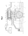
- Fig. 1 is a longitudinal cross-sectional view of a portion around an installation portion in a cylinder head cover in accordance with a first embodiment of the present invention;
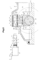
- Fig. 2 is a longitudinal cross-sectional view showing the portion around the installation portion of the cylinder head cover in Fig. 1 before an OCV is installed, together with the OCV;
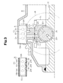
- Fig. 3 is a longitudinal cross-sectional view showing the portion around the installation portion of the cylinder head cover in Fig. 1 before an OCV and a sleeve are installed, together with the sleeve;
- Fig. 4(A) and Fig. 4(B) are perspective views of a sleeve of the cylinder head cover in Fig. 1, in which view points are different at 90 degree from each other around an axis of the sleeve;
- Fig. 5(A) is a plan view of the sleeve in Fig. 4(A) and Fig. 4(B), Fig. 5(B) is a front view of the sleeve, Fig. 5(C) is a bottom view of the sleeve, Fig. 5(D) is a rear view of the sleeve, Fig. 5(E) is a left side view of the sleeve, and Fig. 5(F) is a right side view of the sleeve;
- Fig. 6(A) is a broken perspective view at a vertical plane of the sleeve in the attitude in Fig. 4(A), and Fig. 6 (B) is a broken perspective view at a vertical plane of the sleeve in the attitude in Fig. 4(B);
- Figs. 7 (A) and 7(B) are perspective views of a sleeve in accordance with a second embodiment of the present invention in which view points are different at 90 degree from each other around an axis of the sleeve;
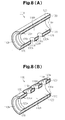
- Fig. 8(A) is a broken perspective view at a vertical plane of the sleeve in the attitude in Fig. 7(A), and Fig. 8(B) is a broken perspective view at a vertical plane of the sleeve in an attitude in Fig. 7(B);
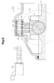
- Fig. 9 is a longitudinal cross-sectional view showing a portion around an installation portion in a cylinder head cover in accordance with the second embodiment before an OCV is installed, together with the OCV;
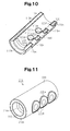
- Fig. 10 is a broken perspective view of a sleeve at a horizontal surface in accordance with another embodiment of the present invention; and
- Fig. 11 is a perspective view of a sleeve in accordance with an other embodiment of the present invention.
- A description will be given of a first embodiment in accordance with the present invention with reference to Figs. 1 to 6.
- A cover
main body 8 of acylinder head cover 2 for an engine in accordance with the first embodiment shown in Fig. 1 is cast from metal. The covermain body 8 includes aninstallation portion 6 to which an oil control valve (OCV) 4 is installed. Theinstallation portion 6 is provided with acylindrical installation hole 10 shown in Fig. 3 and formed at a time of casting the covermain body 8. Theinstallation hole 10 may be finished by cutting or grinding as necessary after casting the covermain body 8. - An
outer end 10a of theinstallation hole 10 is open to an outside of the covermain body 8, and an inner end of theinstallation hole 10 is open to an inner side of the covermain body 8. A ring-shaped locking protrusion 10b is provided in a peripheral edge of the inner end of theinstallation hole 10. - An oil
passage connection portion 12 is provided below theinstallation hole 10. Twoconnection oil passages passage connection portion 12. Upper ends of theconnection oil passages installation hole 10. Lower ends of theconnection oil passages contact surface 12c brought into contact with acam cap 14. In a state in which thecylinder head cover 2 is attached to acylinder head 16, camcap oil passages cam cap 14 respectively communicate with theconnection oil passages -
Oil passages installation portion 6. Theoil passages 6a to 6c extend orthogonal to an extending direction of theconnection oil passages installation hole 10. In Figs. 2 and 3, since theoil passages 6a to 6c are provided in a portion of theinstallation portion 6 in a cut side, the openings of theoil passages 6a to 6c are shown by broken lines. - The center oil passage (the supply oil passage) 6b is connected to a hydraulic oil supply passage (not shown) provided in the
cylinder head 16 via a pipe, the other oil passage or the like. Accordingly, hydraulic oil is supplied into theinstallation hole 10 from the hydraulic oil supply passage via thesupply oil passage 6b. - The oil passages (the drain oil passages) 6a and 6c in both sides have end portions open to an inner side of the cover
main body 8, and the hydraulic oil within theinstallation hole 10 is drained to the inner side of the covermain body 8 via thedrain oil passages - As shown in Fig. 2, a
sleeve 18 is installed to theinstallation hole 10. As shown in Figs. 4 to 6, thesleeve 18 has a cylindrical sleevemain body 18a. The sleevemain body 18a is formed of a metal material such as an aluminum alloy, or an iron alloy. The sleevemain body 18a may be formed of the same metal material as that of thespool housing 5 of theOCV 4 in Figs. 1 and 2. - The sleeve
main body 18a is provided withoil holes ports spool housing 5 of theOCV 4. Theoil holes 18c to 18g connect anaccommodation hole 18b corresponding to an internal space of thesleeve 18 with an outside of thesleeve 18. Atapered surface 18h is provided in an end portion of the sleevemain body 18a in the side to which theOCV 4 is inserted, for making it easy to insert the OCV4 to theaccommodation hole 18b. In Figs. 1 to 3, since theoil holes sleeve 18 in the cut side, theoil holes - An outer circumferential surface of the sleeve
main body 18a except theoil holes 18c to 18g is covered by a rubber-likeelastic body layer 20 made of a rubber resin. The rubber-likeelastic body layer 20 includesprotrusions oil holes 18c to 18g so as to surround therespective oil holes 18c to 18g. - The rubber-like
elastic body layer 20 may be formed in the sleevemain body 18a by any method. For example, a liquid or a powder material, which turns into a rubber-like elastic body, may be used. In this case, such a liquid or a powder material is applied to the outer circumferential surface of the sleevemain body 18a by means of printing, dipping or the like, and thereafter baked. Theprotrusions - An outer diameter of the
sleeve 18, in which the rubber-likeelastic body layer 20 is formed on the outer circumferential surface of the sleevemain body 18a as mentioned above, is slightly larger than an inner diameter of theinstallation hole 10. Accordingly, thesleeve 18 is accommodated in theinstallation hole 10 in a state in which the rubber-likeelastic body layer 20 is compressed along a radial direction of thesleeve 18. At this time, theprotrusions elastic body layer 20. - The cover
main body 8 is fixed to thecylinder head 16 by being fastened by bolts or the like, before installing theOCV 4 to thesleeve 18 as shown in Fig. 2, or after installing theOCV 4 to thesleeve 18. - When attaching the cover
main body 8 to thecylinder head 16, a substantially figure-of-eightseal ring 22 is previously arranged in a lower surface of the oilpassage connection portion 12 in such a manner as to surround the openings of theconnection oil passages passage connection portion 12. Theseal ring 22 serves as an oil seal function in a contact surface between the oilpassage connection portion 12 and thecam cap 14. - The
OCV 4 is installed to theinstallation portion 6 in a state in which thesleeve 18 is accommodated in theinstallation hole 10. That is, thespool housing 5 of theOCV 4 is installed to theaccommodation hole 18b of thesleeve 18. Accordingly, a structure shown in Fig. 1 is completed. - The sleeve
main body 18a is made of a metal material, and theaccommodation hole 18b of thesleeve 18 is formed at a high accuracy in such a manner that a predetermined clearance is secured between a surface defining theaccommodation hole 18b and thespool housing 5. Accordingly, even if a cast defect of the covermain body 8 appears on the surface defining theinstallation hole 10, the oil tightness between theOCV 4 and thesleeve 18 is reliably maintained by an O-ring 5f provided in a proximal end portion of thespool housing 5. - Further, the outer circumferential surface of the
sleeve 18 is constituted by the rubber-likeelastic body layer 20, and each of the oil holes 18c to 18g is surrounded by theprotrusions installation hole 10, it is possible to reliably maintain the oil tightness between thesleeve 18 and the surface defining theinstallation hole 10. - Therefore, in accordance with the present embodiment, even if the cast defect appears on the surface defining the
installation hole 10, it is possible to install theOCV 4 to thecylinder head cover 2 at a high oil tightness. - The
OCV 4 is provided with abracket 4a. TheOCV 4 is prevented from coming off and is prevented from rotating by fastening thebracket 4a to the covermain body 8 by a bolt after inserting thespool housing 5 to theaccommodation hole 18b of thesleeve 18. - An electronic control unit (ECU) 24 shown in Fig. 1 controls an exciting current applied to an
electromagnetic solenoid portion 4b of theOCV 4 in correspondence to an operating state of the engine. Accordingly, the hydraulic oil supplied to aport 5b of thespool housing 5 via thesupply oil passage 6b and theoil hole 18d is supplied to one of theoil holes ports valve actuation mechanism 28 via theconnection oil passages cap oil passages oil passages 26a and 27b provided within acamshaft 26. For example, when the hydraulic oil is supplied to the variablevalve actuation mechanism 28 via theconnection oil passage 12a, the camcap oil passage 14a, and theoil passage 26a, and the hydraulic oil is drained from the variablevalve actuation mechanism 28 via theconnection oil passage 12b, the camcap oil passage 14b, and theoil passage 26b, the variablevalve actuation mechanism 28 is controlled to retard the phase. As a result, the phase of thecamshaft 26 is retarded with respect to atiming sprocket 30 and a valve timing is retarded. In contrast, when the hydraulic oil is supplied to the variablevalve actuation mechanism 28 via theconnection oil passage 12b, the camcap oil passage 14b, and theoil passage 26b, and the hydraulic oil is drained from the variablevalve actuation mechanism 28 via theconnection oil passage 12a, the camcap oil passage 14a and theoil passage 26a, the variablevalve actuation mechanism 28 is controlled to advance the phase. As a result, the phase of thecamshaft 26 is advanced with respect to thetiming sprocket 30 and the valve timing is advanced. - In accordance with the first embodiment described above, the following advantages are obtained.
- The sleeve
main body 18a of thesleeve 18 has an outer surface having a shape corresponding to a shape of the surface defining theinstallation hole 10, and has an inner surface having a shape corresponding to an outer surface of theOCV 4, particularly to an outer surface of thespool housing 5. Since the shape of the sleevemain body 18a is comparatively simple, for the matter of that the sleevemain body 18a is made of the metal, it is possible to easily obtain the structure having no defect and having a high dimensional accuracy. Accordingly, the oil tightness between the sleevemain body 18a and theOCV 4 is high. - An outer circumferential surface of the sleeve
main body 18a is covered by a rubber-likeelastic body layer 20 made of a rubber resin. Even if the cast defect is generated in the covermain body 8, particularly in theinstallation portion 6 having a complicated shape, and the defect appears on the surface defining theinstallation hole 10, the rubber-likeelastic body layer 20 is deformed in such a manner as to fill a gap generated between the surface defining theinstallation hole 10 and thesleeve 18 due to the defect, whereby it is possible to achieve an oil tightness between the surface defining theinstallation hole 10 and thesleeve 18. Further, even if the dimensional accuracy of theinstallation hole 10 is low, and a difference of thermal expansion rate between theOCV 4 and the covermain body 8 exists, the rubber-likeelastic body layer 20 is deformed in such a manner as to fill the gap generated between the surface defining theinstallation hole 10 and thesleeve 18, whereby it is possible to achieve the oil tightness between the surface defining theinstallation hole 10 and thesleeve 18. - Each of the oil holes 18c to 18g of the
sleeve 18 is surrounded by theprotrusions installation hole 10 and thesleeve 18 becomes stronger particularly in the periphery of the oil holes 18c to 18g, and it is possible to prevent the hydraulic oil from leaking via the oil holes 18c to 18g. - As mentioned above, in accordance with the present embodiment, it is possible to install the
OCV 4 to thecylinder head cover 2 at a high oil tightness. As a result, theECU 24 can execute a hydraulic control via theOCV 4 at a high accuracy. - A description will be given below of a second embodiment in accordance with the present invention with reference to Figs. 7 to 9.
- The second embodiment is substantially the same as the first embodiment except a
sleeve 118. Thesleeve 118 in accordance with the second embodiment is shown in Figs. 7 and 8. A sleevemain body 118a of thesleeve 118 has the same shape as that of the sleevemain body 18a in accordance with the first embodiment, and hasoil holes main body 118a is covered by a rubber-likeelastic body layer 120 includingprotrusions elastic body layer 120 covers not only the outer circumferential surface of the sleevemain body 118a, but also a surface defining each of the oil holes 118c to 118g and an inner circumferential surface of the sleevemain body 118a, and covers the entire surface of the sleevemain body 118a except an end portion in the side to which theOCV 104 provided with atapered surface 118h is inserted. - A
seal lip 120c constituted by a thin rubber-like elastic body is provided in an inner periphery of an end portion of the sleevemain body 118a in the side to which theOCV 4 is inserted over the entire circumference. Theseal lip 120c serves as serving as a projection, - As shown in Fig. 9, the
sleeve 118 is fitted to theinstallation hole 10 of the covermain body 8. After fitting to theinstallation hole 10, aspool housing 105 of theOCV 104 is inserted to anaccommodation hole 118b of thesleeve 118. In theOCV 4 in accordance with the first embodiment shown in Figs. 1 and 2, the peripheral groove is provided in the proximal end portion of thespool housing 5 and the O-ring 5f is fitted to the peripheral groove, however, no O-ring is provided in thespool housing 105 of theOCV 104 in accordance with the second embodiment. - A portion between the
spool housing 105 of theOCV 104 installed to thesleeve 118 and thesleeve 118 is oil sealed by a portion of the rubber-likeelastic body layer 120 covering the inner circumferential surface of the sleevemain body 118a. - Further, since a distal end of the
seal lip 120c is engaged with the outer circumferential surface of thespool housing 105, it is possible to avoid leakage of the hydraulic oil to the outside of the covermain body 8 even if the hydraulic oil leaks to the portion between thespool housing 105 and thesleeve 118. That is, it is possible to prevent the hydraulic oil from leaking to the outside of thecylinder head cover 102, without setting the groove or the O-ring in thespool housing 105. - In accordance with the second embodiment described above, the following advantages are obtained in addition to the advantages obtained by the first embodiment.
- Since the rubber-like
elastic body layer 120 is also provided in the inner circumferential surface of the sleevemain body 118a, thespool housing 105 of theOCV 104 inserted to theaccommodation hole 118b of thesleeve 118 is closely contacted to thesleeve 118. Therefore, in accordance with the present embodiment, it is possible to install theOCV 104 to thecylinder head cover 102 at a higher oil tightness. - It is possible to prevent the hydraulic oil from leaking to the outside of the cover
main body 8 from the portion between theOCV 104 and the sleevemain body 118a, by theseal lip 120c provided in thesleeve 118 without setting the structure for the oil seal such as the groove or the O-ring in theOCV 104. Accordingly, it is possible to simplify the structure of theOCV 104 and it is possible to reduce the manufacturing costs of theOCV 104. - The rubber-like
elastic body layer 120 covers the entire surface of the sleevemain body 118a except the end portion in the side to which theOCV 104 is inserted. Accordingly, the edge of the rubber-likeelastic body layer 120 is positioned only in an end portion in the side to which theOCV 104 is inserted. Therefore, it is possible to easily execute deburring of the edge of the rubber-likeelastic body layer 120 which is executed as necessary after an exposure forming of the rubber-likeelastic body layer 120. - In the second embodiment, the
seal lip 120c does not need to be a thin film the thickness of which is reduced toward the distal end, but may have a cross-sectional shape that is the same as that of theprotrusions - In the second embodiment, the tapered
surface 118h of the sleevemain body 118a is not covered by the rubber-likeelastic body layer 120, however, the taperedsurface 118h of the sleevemain body 118a may be also covered by the rubber-likeelastic body layer 120. Alternatively, the entire surface of the sleevemain body 118a may be covered by the rubber-likeelastic body layer 120. - In the second embodiment, in addition to the provision of the
protrusions sleeve 118, theprotrusions sleeve 118, as shown in Fig. 10. Theprotrusions 120d to 120h correspond to a thick portion of the rubber-likeelastic body layer 120, and are respectively provided around the oil holes 118c to 118g in such a manner as to surround the oil holes 118c to 118g. - In the first embodiment, it is possible to omit the
tapered surface 18h which is provided in the end portion of the sleevemain body 18a in the side to which theOCV 4 is inserted. In the second embodiment, it is possible to omit the taperedsurface 118h provided in the end portion of the sleevemain body 118a in the side to which theOCV 104 is inserted. For example, as shown in Fig. 11, no tapered surface may be provided in an end portion of a sleevemain body 218a. In asleeve 218 shown in Fig. 11, an outer circumferential surface and an inner circumferential surface of the sleevemain body 218a are covered by a rubber-likeelastic body layer 220. Further,protrusions sleeve 218, and aseal lip 220c is provided in an inner circumferential surface of thesleeve 218. If the inner diameter of the sleevemain body 218a is set sufficiently larger than the outer diameter of a spool housing of the OCV, insert the spool housing is easily inserted without any tapered surface. Since the rubber-likeelastic body layer 220 is provided also in the inner circumferential surface of the sleevemain body 218a, there is no risk that an oil leakage is generated even if the inner diameter of the sleevemain body 218a is larger in some degree than the outer diameter of the spool housing. - In the first embodiment, the
OCV 4 is arranged in theaccommodation hole 18b of thesleeve 18 after thesleeve 18 is arranged in theinstallation hole 10 of the covermain body 8, however, thesleeve 18 integrally formed with theOCV 4 may be arranged in theinstallation hole 10 of the covermain body 8 after theOCV 4 is arranged in theaccommodation hole 18b of thesleeve 18. In the same manner, in the second embodiment, thesleeve 118 integrally formed with theOCV 104 may be arranged in theinstallation hole 10 of the covermain body 8 after theOCV 104 is arranged in theaccommodation hole 118b of thesleeve 118. - In the first and second embodiments, the cover
main body 8 may be made of a resin in place of the metal. In accordance with the first and second embodiments, it is possible to install theOCV cylinder head cover main body 8 being made of the resin, such as the poorness in the dimensional accuracy of theinstallation hole 10, the difference of thermal expansion rate between theOCV main body 8, and the creep phenomenon.
Claims (7)
- A sleeve allowing insertion of an oil control valve and being inserted, when used, to an installation hole provided in a cylinder head cover, the sleeve being characterized by including:a tubular sleeve main body having an outer surface of a shape corresponding to a shape of a surface defining the installation hole, and having an inner surface of a shape corresponding to an outer surface of the control valve;an oil hole provided in the sleeve main body in such a manner as to connect an internal space of the sleeve with an outside of the sleeve so as to supply and drain a hydraulic oil between the oil control valve and an oil passage provided in the cylinder head cover; anda rubber-like elastic body layer provided in such a manner as to cover the outer surface of the sleeve main body, said rubber-like elastic body layer having a protrusion provided in the periphery of the oil hole so as to surround the oil hole.
- The sleeve according to claim 1, characterized in that the sleeve main body is formed of a metal material.
- The sleeve according to claim 1 or 2, characterized in that the rubber-like elastic body layer is formed of a rubber resin.
- The sleeve according to any one of claims 1 to 3, characterized in that the rubber-like elastic body layer is formed by baking a material for forming a rubber-like elastic body.
- The sleeve according to any one of claims 1 to 4, characterized in that the rubber-like elastic body layer is provided in such a manner as to cover the inner surface in addition to the outer surface of the sleeve main body.
- The sleeve according to claim 5, characterized in that the rubber-like elastic body layer includes a projection provided in the entire inner circumference of an end portion of the sleeve main body in the side to which the oil control valve is inserted.
- A cylinder head cover of an internal combustion engine, characterized in that said cylinder head cover has an installation hole, and the sleeve according to any one of claims 1 to 6 is arranged in said installation hole.
Applications Claiming Priority (2)
| Application Number | Priority Date | Filing Date | Title |
|---|---|---|---|
| JP2005010910A JP4150728B2 (en) | 2005-01-18 | 2005-01-18 | Sleeve and cylinder head cover |
| PCT/JP2006/300430 WO2006077788A1 (en) | 2005-01-18 | 2006-01-16 | Sleeve and cylinder head cover |
Publications (3)
| Publication Number | Publication Date |
|---|---|
| EP1840362A1 true EP1840362A1 (en) | 2007-10-03 |
| EP1840362A4 EP1840362A4 (en) | 2010-05-19 |
| EP1840362B1 EP1840362B1 (en) | 2011-04-06 |
Family
ID=36692178
Family Applications (1)
| Application Number | Title | Priority Date | Filing Date |
|---|---|---|---|
| EP06711711A Expired - Lifetime EP1840362B1 (en) | 2005-01-18 | 2006-01-16 | Sleeve and cylinder head cover |
Country Status (6)
| Country | Link |
|---|---|
| US (1) | US7789056B2 (en) |
| EP (1) | EP1840362B1 (en) |
| JP (1) | JP4150728B2 (en) |
| CN (1) | CN100540874C (en) |
| DE (1) | DE602006021136D1 (en) |
| WO (1) | WO2006077788A1 (en) |
Cited By (2)
| Publication number | Priority date | Publication date | Assignee | Title |
|---|---|---|---|---|
| WO2009092609A1 (en) * | 2008-01-26 | 2009-07-30 | Schaeffler Kg | Hydraulic medium insert for a control valve in a hydraulic actuator |
| WO2025008560A1 (en) * | 2023-07-04 | 2025-01-09 | Wärtsilä Finland Oy | Cylinder head, cylinder head cover, cylinder head assembly and piston engine |
Families Citing this family (12)
| Publication number | Priority date | Publication date | Assignee | Title |
|---|---|---|---|---|
| US6308059B1 (en) | 1997-12-12 | 2001-10-23 | Joseph Domes | Ruggedized tradesworkers radio |
| US7609027B2 (en) | 2001-11-09 | 2009-10-27 | Milwaukee Electric Tool Corporation | Electrical component, audio component, or electrical combination having a selectively connectable battery charger |
| JP4719725B2 (en) * | 2007-08-23 | 2011-07-06 | 本田技研工業株式会社 | Valve controller for multi-cylinder internal combustion engine |
| CN101779010B (en) * | 2007-08-23 | 2012-07-18 | 本田技研工业株式会社 | Valve gear control device for internal combustion engine |
| JP4691077B2 (en) * | 2007-08-23 | 2011-06-01 | 本田技研工業株式会社 | Valve control device for internal combustion engine |
| AT506468B1 (en) * | 2009-03-24 | 2010-12-15 | Avl List Gmbh | CYLINDER HEAD OF AN INTERNAL COMBUSTION ENGINE |
| GB2477334A (en) * | 2010-02-01 | 2011-08-03 | Gm Global Tech Operations Inc | Fixing system for detachably fixing a control valve 10 to an internal combustion engine |
| US8261708B2 (en) | 2010-04-07 | 2012-09-11 | Eaton Corporation | Control valve mounting system |
| CN102400813A (en) * | 2010-09-15 | 2012-04-04 | 重庆长安汽车股份有限公司 | Engine front cover having function of protecting oil control valve and suspension installation structure |
| DE102017104348B3 (en) * | 2017-03-02 | 2018-05-30 | Schaeffler Technologies AG & Co. KG | Hydraulic camshaft adjuster |
| DE102019205032B4 (en) * | 2019-04-08 | 2021-03-11 | Hawe Hydraulik Se | Hydraulic component with a component housing and a connection block |
| CN110454365A (en) * | 2019-08-14 | 2019-11-15 | 珠海格力节能环保制冷技术研究中心有限公司 | Compressor and refrigeration equipment with it |
Family Cites Families (9)
| Publication number | Priority date | Publication date | Assignee | Title |
|---|---|---|---|---|
| JPH10317934A (en) | 1997-05-15 | 1998-12-02 | Daihatsu Motor Co Ltd | Camshaft lubricating device |
| JP3525709B2 (en) | 1997-10-30 | 2004-05-10 | マツダ株式会社 | Variable valve timing device for internal combustion engine |
| JP3468280B2 (en) * | 1998-10-26 | 2003-11-17 | 三菱自動車工業株式会社 | Variable cam phase device |
| US6382148B1 (en) * | 1999-06-10 | 2002-05-07 | Unisia Jecs Corporation | Oil pressure control apparatus for an internal combustion engine |
| JP4517513B2 (en) * | 2001-02-14 | 2010-08-04 | マツダ株式会社 | Lubricating device for variable valve timing mechanism of internal combustion engine |
| JP3966003B2 (en) * | 2002-02-05 | 2007-08-29 | 日産自動車株式会社 | Internal combustion engine |
| DE10223431B4 (en) * | 2002-05-25 | 2004-07-08 | Ina-Schaeffler Kg | Internal combustion engine with at least two camshafts arranged side by side, each with a device for adjusting the angle of rotation relative to a crankshaft |
| JP3911609B2 (en) * | 2002-06-29 | 2007-05-09 | 現代自動車株式会社 | Engine cylinder head oil supply structure |
| JP4253635B2 (en) * | 2004-11-30 | 2009-04-15 | トヨタ自動車株式会社 | Cylinder head cover |
-
2005
- 2005-01-18 JP JP2005010910A patent/JP4150728B2/en not_active Expired - Fee Related
-
2006
- 2006-01-16 WO PCT/JP2006/300430 patent/WO2006077788A1/en not_active Ceased
- 2006-01-16 EP EP06711711A patent/EP1840362B1/en not_active Expired - Lifetime
- 2006-01-16 US US11/794,141 patent/US7789056B2/en not_active Expired - Fee Related
- 2006-01-16 DE DE602006021136T patent/DE602006021136D1/en not_active Expired - Lifetime
- 2006-01-16 CN CNB2006800025835A patent/CN100540874C/en not_active Expired - Fee Related
Cited By (3)
| Publication number | Priority date | Publication date | Assignee | Title |
|---|---|---|---|---|
| WO2009092609A1 (en) * | 2008-01-26 | 2009-07-30 | Schaeffler Kg | Hydraulic medium insert for a control valve in a hydraulic actuator |
| CN101918682B (en) * | 2008-01-26 | 2012-12-12 | 谢夫勒科技股份两合公司 | Pressure medium guide inserts for control valves in hydraulic adjustment units |
| WO2025008560A1 (en) * | 2023-07-04 | 2025-01-09 | Wärtsilä Finland Oy | Cylinder head, cylinder head cover, cylinder head assembly and piston engine |
Also Published As
| Publication number | Publication date |
|---|---|
| EP1840362B1 (en) | 2011-04-06 |
| WO2006077788A1 (en) | 2006-07-27 |
| JP2006200390A (en) | 2006-08-03 |
| CN100540874C (en) | 2009-09-16 |
| US7789056B2 (en) | 2010-09-07 |
| US20080088095A1 (en) | 2008-04-17 |
| DE602006021136D1 (en) | 2011-05-19 |
| EP1840362A4 (en) | 2010-05-19 |
| JP4150728B2 (en) | 2008-09-17 |
| CN101107437A (en) | 2008-01-16 |
Similar Documents
| Publication | Publication Date | Title |
|---|---|---|
| EP1840362B1 (en) | Sleeve and cylinder head cover | |
| US6810842B2 (en) | Oil control valve and installing method thereof | |
| US4364346A (en) | Exhaust timing control device for a two-cycle engine | |
| US7341033B2 (en) | Cylinder head cover | |
| US7121243B2 (en) | Valve case and resin cylinder head cover | |
| EP1000227B1 (en) | Gasket | |
| US7255078B2 (en) | Resin cylinder head cover | |
| CN1330858C (en) | Valve timing control system of IC engine | |
| CN100374705C (en) | Resin cylinder head cover | |
| JP2007107479A (en) | Oil controller valve mounting structure | |
| RU2417324C2 (en) | Cover of distributing shafts | |
| US7104694B2 (en) | Bearing apparatus for camshaft in engine | |
| WO2014073109A1 (en) | Valve timing control device and method of assembly thereof | |
| US20070102887A1 (en) | Cylinder head gasket with an oil drainback tube fastener | |
| JP4517513B2 (en) | Lubricating device for variable valve timing mechanism of internal combustion engine | |
| JP2000110534A (en) | Cam bearing structure of internal combustion engine | |
| MXPA01004120A (en) | Integrated push rod locator in cylinder head gasket. | |
| CN1863992B (en) | Apparatus for aligning push rods | |
| JP4176063B2 (en) | Oil control valve sleeve and cylinder head cover | |
| JP4243790B2 (en) | Counter-piston disc brake caliper | |
| JP4100807B2 (en) | Cylinder for water-cooled internal combustion engine | |
| JPH1181931A (en) | Valve direct-acting engine | |
| EP0568157A1 (en) | Low-mass, direct-acting hydraulic valve-lifter | |
| JPS645074Y2 (en) | ||
| WO2024095432A1 (en) | Cylinder head structure of internal combustion engine |
Legal Events
| Date | Code | Title | Description |
|---|---|---|---|
| PUAI | Public reference made under article 153(3) epc to a published international application that has entered the european phase |
Free format text: ORIGINAL CODE: 0009012 |
|
| 17P | Request for examination filed |
Effective date: 20070703 |
|
| AK | Designated contracting states |
Kind code of ref document: A1 Designated state(s): DE FR GB |
|
| RBV | Designated contracting states (corrected) |
Designated state(s): DE FR GB |
|
| DAX | Request for extension of the european patent (deleted) | ||
| A4 | Supplementary search report drawn up and despatched |
Effective date: 20100416 |
|
| RIC1 | Information provided on ipc code assigned before grant |
Ipc: F16M 1/026 20060101ALI20100810BHEP Ipc: F01L 1/34 20060101ALI20100810BHEP Ipc: F02F 7/00 20060101AFI20100810BHEP |
|
| GRAP | Despatch of communication of intention to grant a patent |
Free format text: ORIGINAL CODE: EPIDOSNIGR1 |
|
| GRAS | Grant fee paid |
Free format text: ORIGINAL CODE: EPIDOSNIGR3 |
|
| GRAA | (expected) grant |
Free format text: ORIGINAL CODE: 0009210 |
|
| RIN1 | Information on inventor provided before grant (corrected) |
Inventor name: YOSHIJIMA, KAZUYA Inventor name: HASEGAWA, NAOHIRO |
|
| AK | Designated contracting states |
Kind code of ref document: B1 Designated state(s): DE FR GB |
|
| REG | Reference to a national code |
Ref country code: GB Ref legal event code: FG4D |
|
| REF | Corresponds to: |
Ref document number: 602006021136 Country of ref document: DE Date of ref document: 20110519 Kind code of ref document: P |
|
| REG | Reference to a national code |
Ref country code: DE Ref legal event code: R096 Ref document number: 602006021136 Country of ref document: DE Effective date: 20110519 |
|
| PLBE | No opposition filed within time limit |
Free format text: ORIGINAL CODE: 0009261 |
|
| STAA | Information on the status of an ep patent application or granted ep patent |
Free format text: STATUS: NO OPPOSITION FILED WITHIN TIME LIMIT |
|
| 26N | No opposition filed |
Effective date: 20120110 |
|
| REG | Reference to a national code |
Ref country code: DE Ref legal event code: R097 Ref document number: 602006021136 Country of ref document: DE Effective date: 20120110 |
|
| GBPC | Gb: european patent ceased through non-payment of renewal fee |
Effective date: 20120116 |
|
| REG | Reference to a national code |
Ref country code: FR Ref legal event code: ST Effective date: 20120928 |
|
| PG25 | Lapsed in a contracting state [announced via postgrant information from national office to epo] |
Ref country code: DE Free format text: LAPSE BECAUSE OF NON-PAYMENT OF DUE FEES Effective date: 20120801 Ref country code: GB Free format text: LAPSE BECAUSE OF NON-PAYMENT OF DUE FEES Effective date: 20120116 |
|
| REG | Reference to a national code |
Ref country code: DE Ref legal event code: R119 Ref document number: 602006021136 Country of ref document: DE Effective date: 20120801 |
|
| PG25 | Lapsed in a contracting state [announced via postgrant information from national office to epo] |
Ref country code: FR Free format text: LAPSE BECAUSE OF NON-PAYMENT OF DUE FEES Effective date: 20120131 |