EP1840090A2 - Hybrid water desalination system and method of operation - Google Patents
Hybrid water desalination system and method of operation Download PDFInfo
- Publication number
- EP1840090A2 EP1840090A2 EP07104727A EP07104727A EP1840090A2 EP 1840090 A2 EP1840090 A2 EP 1840090A2 EP 07104727 A EP07104727 A EP 07104727A EP 07104727 A EP07104727 A EP 07104727A EP 1840090 A2 EP1840090 A2 EP 1840090A2
- Authority
- EP
- European Patent Office
- Prior art keywords
- converter
- coupled
- compressor
- desalination
- electrical power
- Prior art date
- Legal status (The legal status is an assumption and is not a legal conclusion. Google has not performed a legal analysis and makes no representation as to the accuracy of the status listed.)
- Withdrawn
Links
Images




Classifications
-
- C—CHEMISTRY; METALLURGY
- C02—TREATMENT OF WATER, WASTE WATER, SEWAGE, OR SLUDGE
- C02F—TREATMENT OF WATER, WASTE WATER, SEWAGE, OR SLUDGE
- C02F1/00—Treatment of water, waste water, or sewage
- C02F1/02—Treatment of water, waste water, or sewage by heating
- C02F1/04—Treatment of water, waste water, or sewage by heating by distillation or evaporation
- C02F1/047—Treatment of water, waste water, or sewage by heating by distillation or evaporation using eolic energy
-
- C—CHEMISTRY; METALLURGY
- C02—TREATMENT OF WATER, WASTE WATER, SEWAGE, OR SLUDGE
- C02F—TREATMENT OF WATER, WASTE WATER, SEWAGE, OR SLUDGE
- C02F1/00—Treatment of water, waste water, or sewage
- C02F1/02—Treatment of water, waste water, or sewage by heating
- C02F1/04—Treatment of water, waste water, or sewage by heating by distillation or evaporation
- C02F1/041—Treatment of water, waste water, or sewage by heating by distillation or evaporation by means of vapour compression
-
- F—MECHANICAL ENGINEERING; LIGHTING; HEATING; WEAPONS; BLASTING
- F03—MACHINES OR ENGINES FOR LIQUIDS; WIND, SPRING, OR WEIGHT MOTORS; PRODUCING MECHANICAL POWER OR A REACTIVE PROPULSIVE THRUST, NOT OTHERWISE PROVIDED FOR
- F03D—WIND MOTORS
- F03D9/00—Adaptations of wind motors for special use; Combinations of wind motors with apparatus driven thereby; Wind motors specially adapted for installation in particular locations
-
- F—MECHANICAL ENGINEERING; LIGHTING; HEATING; WEAPONS; BLASTING
- F03—MACHINES OR ENGINES FOR LIQUIDS; WIND, SPRING, OR WEIGHT MOTORS; PRODUCING MECHANICAL POWER OR A REACTIVE PROPULSIVE THRUST, NOT OTHERWISE PROVIDED FOR
- F03D—WIND MOTORS
- F03D9/00—Adaptations of wind motors for special use; Combinations of wind motors with apparatus driven thereby; Wind motors specially adapted for installation in particular locations
- F03D9/007—Adaptations of wind motors for special use; Combinations of wind motors with apparatus driven thereby; Wind motors specially adapted for installation in particular locations the wind motor being combined with means for converting solar radiation into useful energy
-
- F—MECHANICAL ENGINEERING; LIGHTING; HEATING; WEAPONS; BLASTING
- F03—MACHINES OR ENGINES FOR LIQUIDS; WIND, SPRING, OR WEIGHT MOTORS; PRODUCING MECHANICAL POWER OR A REACTIVE PROPULSIVE THRUST, NOT OTHERWISE PROVIDED FOR
- F03D—WIND MOTORS
- F03D9/00—Adaptations of wind motors for special use; Combinations of wind motors with apparatus driven thereby; Wind motors specially adapted for installation in particular locations
- F03D9/008—Adaptations of wind motors for special use; Combinations of wind motors with apparatus driven thereby; Wind motors specially adapted for installation in particular locations the wind motor being combined with water energy converters, e.g. a water turbine
-
- F—MECHANICAL ENGINEERING; LIGHTING; HEATING; WEAPONS; BLASTING
- F03—MACHINES OR ENGINES FOR LIQUIDS; WIND, SPRING, OR WEIGHT MOTORS; PRODUCING MECHANICAL POWER OR A REACTIVE PROPULSIVE THRUST, NOT OTHERWISE PROVIDED FOR
- F03D—WIND MOTORS
- F03D9/00—Adaptations of wind motors for special use; Combinations of wind motors with apparatus driven thereby; Wind motors specially adapted for installation in particular locations
- F03D9/10—Combinations of wind motors with apparatus storing energy
- F03D9/11—Combinations of wind motors with apparatus storing energy storing electrical energy
-
- F—MECHANICAL ENGINEERING; LIGHTING; HEATING; WEAPONS; BLASTING
- F03—MACHINES OR ENGINES FOR LIQUIDS; WIND, SPRING, OR WEIGHT MOTORS; PRODUCING MECHANICAL POWER OR A REACTIVE PROPULSIVE THRUST, NOT OTHERWISE PROVIDED FOR
- F03D—WIND MOTORS
- F03D9/00—Adaptations of wind motors for special use; Combinations of wind motors with apparatus driven thereby; Wind motors specially adapted for installation in particular locations
- F03D9/20—Wind motors characterised by the driven apparatus
- F03D9/25—Wind motors characterised by the driven apparatus the apparatus being an electrical generator
-
- H—ELECTRICITY
- H02—GENERATION; CONVERSION OR DISTRIBUTION OF ELECTRIC POWER
- H02J—ELECTRIC POWER NETWORKS; CIRCUIT ARRANGEMENTS OR SYSTEMS FOR SUPPLYING OR DISTRIBUTING ELECTRIC POWER; SYSTEMS FOR STORING ELECTRIC ENERGY
- H02J3/00—Circuit arrangements for AC mains or AC distribution networks
- H02J3/38—Arrangements for feeding a single network from two or more generators or sources in parallel; Arrangements for feeding already energised networks from additional generators or sources in parallel
-
- H—ELECTRICITY
- H02—GENERATION; CONVERSION OR DISTRIBUTION OF ELECTRIC POWER
- H02S—GENERATION OF ELECTRIC POWER BY CONVERSION OF INFRARED RADIATION, VISIBLE LIGHT OR ULTRAVIOLET LIGHT, e.g. USING PHOTOVOLTAIC [PV] MODULES
- H02S10/00—PV power plants; Combinations of PV energy systems with other systems for the generation of electric power
- H02S10/10—PV power plants; Combinations of PV energy systems with other systems for the generation of electric power including a supplementary source of electric power, e.g. hybrid diesel-PV energy systems
- H02S10/12—Hybrid wind-PV energy systems
-
- C—CHEMISTRY; METALLURGY
- C02—TREATMENT OF WATER, WASTE WATER, SEWAGE, OR SLUDGE
- C02F—TREATMENT OF WATER, WASTE WATER, SEWAGE, OR SLUDGE
- C02F2103/00—Nature of the water, waste water, sewage or sludge to be treated
- C02F2103/08—Seawater, e.g. for desalination
-
- C—CHEMISTRY; METALLURGY
- C02—TREATMENT OF WATER, WASTE WATER, SEWAGE, OR SLUDGE
- C02F—TREATMENT OF WATER, WASTE WATER, SEWAGE, OR SLUDGE
- C02F2201/00—Apparatus for treatment of water, waste water or sewage
- C02F2201/009—Apparatus with independent power supply, e.g. solar cells, windpower or fuel cells
-
- F—MECHANICAL ENGINEERING; LIGHTING; HEATING; WEAPONS; BLASTING
- F05—INDEXING SCHEMES RELATING TO ENGINES OR PUMPS IN VARIOUS SUBCLASSES OF CLASSES F01-F04
- F05B—INDEXING SCHEME RELATING TO WIND, SPRING, WEIGHT, INERTIA OR LIKE MOTORS, TO MACHINES OR ENGINES FOR LIQUIDS COVERED BY SUBCLASSES F03B, F03D AND F03G
- F05B2220/00—Application
- F05B2220/62—Application for desalination
-
- Y—GENERAL TAGGING OF NEW TECHNOLOGICAL DEVELOPMENTS; GENERAL TAGGING OF CROSS-SECTIONAL TECHNOLOGIES SPANNING OVER SEVERAL SECTIONS OF THE IPC; TECHNICAL SUBJECTS COVERED BY FORMER USPC CROSS-REFERENCE ART COLLECTIONS [XRACs] AND DIGESTS
- Y02—TECHNOLOGIES OR APPLICATIONS FOR MITIGATION OR ADAPTATION AGAINST CLIMATE CHANGE
- Y02A—TECHNOLOGIES FOR ADAPTATION TO CLIMATE CHANGE
- Y02A20/00—Water conservation; Efficient water supply; Efficient water use
- Y02A20/124—Water desalination
-
- Y—GENERAL TAGGING OF NEW TECHNOLOGICAL DEVELOPMENTS; GENERAL TAGGING OF CROSS-SECTIONAL TECHNOLOGIES SPANNING OVER SEVERAL SECTIONS OF THE IPC; TECHNICAL SUBJECTS COVERED BY FORMER USPC CROSS-REFERENCE ART COLLECTIONS [XRACs] AND DIGESTS
- Y02—TECHNOLOGIES OR APPLICATIONS FOR MITIGATION OR ADAPTATION AGAINST CLIMATE CHANGE
- Y02A—TECHNOLOGIES FOR ADAPTATION TO CLIMATE CHANGE
- Y02A20/00—Water conservation; Efficient water supply; Efficient water use
- Y02A20/124—Water desalination
- Y02A20/138—Water desalination using renewable energy
- Y02A20/141—Wind power
-
- Y—GENERAL TAGGING OF NEW TECHNOLOGICAL DEVELOPMENTS; GENERAL TAGGING OF CROSS-SECTIONAL TECHNOLOGIES SPANNING OVER SEVERAL SECTIONS OF THE IPC; TECHNICAL SUBJECTS COVERED BY FORMER USPC CROSS-REFERENCE ART COLLECTIONS [XRACs] AND DIGESTS
- Y02—TECHNOLOGIES OR APPLICATIONS FOR MITIGATION OR ADAPTATION AGAINST CLIMATE CHANGE
- Y02A—TECHNOLOGIES FOR ADAPTATION TO CLIMATE CHANGE
- Y02A20/00—Water conservation; Efficient water supply; Efficient water use
- Y02A20/20—Controlling water pollution; Waste water treatment
- Y02A20/208—Off-grid powered water treatment
- Y02A20/212—Solar-powered wastewater sewage treatment, e.g. spray evaporation
-
- Y—GENERAL TAGGING OF NEW TECHNOLOGICAL DEVELOPMENTS; GENERAL TAGGING OF CROSS-SECTIONAL TECHNOLOGIES SPANNING OVER SEVERAL SECTIONS OF THE IPC; TECHNICAL SUBJECTS COVERED BY FORMER USPC CROSS-REFERENCE ART COLLECTIONS [XRACs] AND DIGESTS
- Y02—TECHNOLOGIES OR APPLICATIONS FOR MITIGATION OR ADAPTATION AGAINST CLIMATE CHANGE
- Y02E—REDUCTION OF GREENHOUSE GAS [GHG] EMISSIONS, RELATED TO ENERGY GENERATION, TRANSMISSION OR DISTRIBUTION
- Y02E10/00—Energy generation through renewable energy sources
- Y02E10/50—Photovoltaic [PV] energy
-
- Y—GENERAL TAGGING OF NEW TECHNOLOGICAL DEVELOPMENTS; GENERAL TAGGING OF CROSS-SECTIONAL TECHNOLOGIES SPANNING OVER SEVERAL SECTIONS OF THE IPC; TECHNICAL SUBJECTS COVERED BY FORMER USPC CROSS-REFERENCE ART COLLECTIONS [XRACs] AND DIGESTS
- Y02—TECHNOLOGIES OR APPLICATIONS FOR MITIGATION OR ADAPTATION AGAINST CLIMATE CHANGE
- Y02E—REDUCTION OF GREENHOUSE GAS [GHG] EMISSIONS, RELATED TO ENERGY GENERATION, TRANSMISSION OR DISTRIBUTION
- Y02E10/00—Energy generation through renewable energy sources
- Y02E10/70—Wind energy
- Y02E10/72—Wind turbines with rotation axis in wind direction
-
- Y—GENERAL TAGGING OF NEW TECHNOLOGICAL DEVELOPMENTS; GENERAL TAGGING OF CROSS-SECTIONAL TECHNOLOGIES SPANNING OVER SEVERAL SECTIONS OF THE IPC; TECHNICAL SUBJECTS COVERED BY FORMER USPC CROSS-REFERENCE ART COLLECTIONS [XRACs] AND DIGESTS
- Y02—TECHNOLOGIES OR APPLICATIONS FOR MITIGATION OR ADAPTATION AGAINST CLIMATE CHANGE
- Y02E—REDUCTION OF GREENHOUSE GAS [GHG] EMISSIONS, RELATED TO ENERGY GENERATION, TRANSMISSION OR DISTRIBUTION
- Y02E10/00—Energy generation through renewable energy sources
- Y02E10/70—Wind energy
- Y02E10/76—Power conversion electric or electronic aspects
-
- Y—GENERAL TAGGING OF NEW TECHNOLOGICAL DEVELOPMENTS; GENERAL TAGGING OF CROSS-SECTIONAL TECHNOLOGIES SPANNING OVER SEVERAL SECTIONS OF THE IPC; TECHNICAL SUBJECTS COVERED BY FORMER USPC CROSS-REFERENCE ART COLLECTIONS [XRACs] AND DIGESTS
- Y02—TECHNOLOGIES OR APPLICATIONS FOR MITIGATION OR ADAPTATION AGAINST CLIMATE CHANGE
- Y02E—REDUCTION OF GREENHOUSE GAS [GHG] EMISSIONS, RELATED TO ENERGY GENERATION, TRANSMISSION OR DISTRIBUTION
- Y02E70/00—Other energy conversion or management systems reducing GHG emissions
- Y02E70/30—Systems combining energy storage with energy generation of non-fossil origin
Definitions
- the invention relates generally to a water desalination system, and more particularly, to a hybrid water desalination system powered by a renewable energy source.
- desalination systems are known and are in use.
- such systems include a water pre-treatment system, a desalination unit and a post-treatment system.
- the desalination of seawater in such systems is achieved through thermal processes or through membrane processes.
- the thermal processes for seawater desalination include multistage-flash distillation (MSF), multi effect distillation (MED) and vapor compression (VC).
- membrane processes include reverse osmosis (RO) and electrodialysis (ED) processes.
- Certain desalination systems employ renewable energy sources for powering the desalination system.
- a mechanical vapor compression (MVC) desalination system may be powered by a wind turbine.
- wind powering of a MVC desalination system may be achieved either by direct mechanical coupling of the turbine shaft to the compressor axle of the desalination system, or by generating electrical power that is utilized to drive the electrical compressor drive.
- the mechanical coupling does not provide any means for power regulation or speed control of the compressor drive.
- the electrical compressor drive has considerable complexity in terms of dual frequency conversion.
- one or more converters are required for frequency conversion from generator to grid frequency.
- additional converters are required for frequency conversion from grid frequency to an optimal compressor drive frequency.
- a converter may be required for providing power supply to a heater of the seawater reservoir in the evaporator.
- Such systems therefore require a large number of converters that adversely affect the investment costs, reliability of the system and, thus, service and maintenance costs. As a result, the cost of water produced by such systems is substantially high.
- a hybrid desalination system includes a renewable energy source for producing electrical power and a desalination unit configured to receive electrical power from the renewable energy source for driving the desalination unit.
- the desalination system also includes a first converter coupled to the renewable energy source and a second converter coupled to the desalination unit, wherein the first and second converters are coupled via a common direct current (DC) link.
- DC direct current
- a hybrid water desalination system in another embodiment, includes a wind turbine configured to drive an electrical generator for producing electrical power and a mechanical vapor compression (MVC) desalination unit configured to receive electrical power from the electrical generator for driving a compressor of the desalination unit.
- the desalination system also includes a first converter coupled to the electrical generator and a second converter coupled to the compressor, wherein the first and second converters are coupled via a common direct current (DC) link.
- DC direct current
- a hybrid water desalination system in another embodiment, includes a photovoltaic generator configured to generate electrical power and a mechanical vapor compression (MVC) desalination unit configured to receive electrical power from the photovoltaic generator for driving a compressor of the desalination unit.
- MVC mechanical vapor compression
- the desalination system also includes a first converter coupled to the photovoltaic generator and a second converter coupled to the compressor, wherein the first and second converters are coupled via a common direct current (DC) link.
- DC direct current
- a method of operating a hybrid water desalination system includes generating electrical power through a wind turbine and coupling the generated electrical power to drive a compressor of a MVC desalination unit via a common DC link of first and second converters coupled to the wind turbine and to the compressor.
- a method of operating a hybrid water desalination system includes generating electrical power through a photovoltaic generator and coupling the generated electrical power to drive a compressor of a MVC desalination unit via a common DC link of first and second converters coupled to the photovoltaic generator and to the compressor.
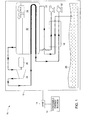
- FIG. 1 is a diagrammatical illustration of a hybrid water desalination system powered by a renewable energy source.
- FIG. 2 is a diagrammatical illustration of an existing wind powered hybrid water desalination system.
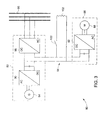
- FIG. 3 is a diagrammatical illustration of a grid coupled wind powered hybrid water desalination system in accordance with certain aspects of the present invention.
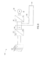
- FIG. 4 is a diagrammatical illustration of a grid coupled hybrid water desalination system powered by a photovoltaic generator in accordance with certain aspects of the present invention.
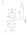
- FIG. 5 is a diagrammatical illustration of an off-grid wind powered hybrid water desalination system in accordance with certain aspects of the present invention.
- FIG. 6 is a diagrammatical illustration of an off-grid hybrid water desalination system powered by a photovoltaic generator in accordance with certain aspects of the present invention.
- FIG. 7 is a diagrammatical illustration of an off-grid wind powered hybrid water desalination system having energy storage capability in accordance with certain aspects of the present invention.
- FIG. 8 is a diagrammatical illustration of an off-grid hybrid water desalination system powered by a photovoltaic generator having energy storage capability in accordance with certain aspects of the present invention.
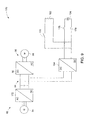
- FIG. 9 is a diagrammatical illustration of another embodiment of an off grid wind powered hybrid water desalination system in accordance with certain aspects of the present invention.
- embodiments of the present invention function to provide a hybrid desalination system that has high system efficiency and low cost of water.
- the present invention provides a desalination system powered by a renewable energy source that has a reduced number of power converters thereby enabling reduced cost of investment and higher reliability.
- the electrical power generated from the renewable energy source 12 such as a wind turbine, may be coupled to a grid 14 to power a mechanical vapor compression (MVC) desalination unit 16.
- the MVC desalination unit 16 includes a heat recuperation exchanger 18 to preheat seawater throughput 20.
- the seawater 20 is heated in the heat recuperation exchanger 18 by a hot discharge of brine blowdown and the distillate.
- the preheated seawater enters an evaporator 22 where it is heated up to its boiling point and some of it is evaporated.
- the water vapor formed in the evaporator is introduced into a compressor 24 after its droplets produced by a separator 28 are removed.
- the compressor 24 is driven by an electric motor 26 and is configured to increase a pressure and consequently a saturation temperature of the water vapor.
- the compressed vapor from the compressor 24 is then fed back into the evaporator 22 to be condensed, providing the thermal energy to evaporate the applied seawater.
- the distilled water produced by this condensation leaves the MVC desalination unit as the product water.
- the condensed vapor from fresh water is extracted along with the concentrated brine that contains the salt, as represented by reference numerals 30 and 32.
- the MVC desalination unit 16 is powered by a wind turbine. In another exemplary embodiment, the MVC desalination unit 16 is powered by a photovoltaic generator. It should be noted that to achieve speed control in the hybrid desalination system 10 by combining an off-the-shelf wind turbine with frequency converter via a grid connection requires four conversion steps, as illustrated by an exemplary existing system in FIG. 2.
- FIG. 2 is a diagrammatical illustration of an existing wind powered hybrid water desalination system 50.
- the desalination system 50 includes a wind turbine 52 that drives a MVC desalination unit 54 of the desalination system 50.
- a grid 56 is coupled to the wind turbine 52 and to the MVC desalination unit 54.
- the grid 56 is configured to operate the MVC desalination unit 54 in a turbine downtime condition.
- the wind turbine 52 includes an electrical generator 58 for generating electrical power.
- to achieve speed control by combining an off-the-shelf wind turbine 52 with frequency converter via the grid connection to a motor drive 60 of the MVC desalination unit 54 requires four conversion steps.
- the steps include conversion from AC to DC, DC to AC, AC to DC and DC-AC.
- the desalination unit 50 includes at least four converters, such as represented by reference numerals 62, 64, 66 and 68.
- the desalination unit may include a fifth converter 70 for providing electrical power to a heating element 72 for heating the seawater 20 (see FIG. 1) in the evaporator 22 (see FIG. 1).
- the existing wind powered desalination system 50 may require as many as five converters for achieving the frequency conversion in the system 50.
- the high number of power converters has an adverse effect both on investment cost and on reliability and thus, service and maintenance cost.
- the cost of water (CoW) is relatively higher as compared to other desalination systems.
- the system efficiency may be substantially reduced due to the electrical losses in the power converters.
- Such disadvantages of the system 50 may be overcome by exemplary hybrid water desalination systems as described below with reference to FIGS. 3-9.
- FIG. 3 is a diagrammatical illustration of a grid coupled wind powered hybrid water desalination system 80 in accordance with certain aspects of the present invention.
- the desalination system 80 includes a wind turbine 82 configured to drive an electrical generator 84 for producing electrical power. Further, the desalination system 80 includes a MVC desalination unit 86 configured to receive electrical power from the electrical generator 84 for driving an electric motor 88 of a compressor of the desalination unit 86.
- the desalination system includes a first converter 90 coupled to the electrical generator 84 and a second converter 92 coupled to the compressor motor 88. The first and second converters 90 and 92 are coupled to one another via a common DC link 94. In this embodiment, the first converter 90 includes an AC-DC converter and the second converter 92 includes a DC-AC converter.
- the desalination system 80 includes an optional grid 96 coupled to the electrical generator 84 via a third converter 98.
- the third converter 98 includes a DC-AC converter that is coupled to the first converter 90.
- the MVC desalination unit 86 is operated via electrical power from the grid 96 in a condition when the wind turbine 82 does not produce any or the required power for driving the MVC desalination unit 86.
- the electrical power from the grid 96 may be utilized to operate the MVC desalination unit 86 during a turbine downtime condition, or a system start-up condition.
- the compressor 24 of the MVC desalination unit 86 is configured to compress vapor generated by evaporation of preheated feed water in the evaporator 22 (see FIG. 1).
- the desalination system 80 (Fig. 3) includes a DC chopper 100 coupled to the DC link 94 for providing electrical power to a water heater 102 for heating the feed water in the evaporator 22.
- the DC chopper 100 includes a semi conductor switch. The DC chopper 100 facilitates dissipation of wind power exceeding the nominal power of the load for water preheating in the evaporator 22.
- the desalination system 80 may be optimized according to power maximization both on the generator side and the load side (or compressor side).
- the load is controlled to match the produced wind power from the wind turbine 82. It should be noted that if the nominal power of the compressor is reached and the produced wind power exceeds this limit, then the excess power may be dumped in the DC chopper 100 for water preheating. In an exemplary embodiment, if this auxiliary load also reaches it's a predefined limit, or the water temperature reaches a desired temperature, then the power of the wind turbine 82 may be reduced on a rotor side of the turbine 82.
- the desalination system 80 described above requires a reduced number of power converters while retaining the flexibility by variable speed control of the system 80.
- the wind turbine 82 of the desalination system 80 may be replaced or supplemented with a photovoltaic generator for driving the MVC desalination unit 86 as will be described below with reference to FIG. 4.
- FIG. 4 is a diagrammatical illustration of a grid coupled hybrid water desalination system 120 powered by a photovoltaic generator 122 in accordance with certain aspects of the present invention.
- the photovoltaic generator 122 is configured to generate electrical power for driving the electric motor 88 of the compressor of the desalination unit 86.
- the desalination system 120 includes a first converter 124 coupled to the photovoltaic generator 122 and the second converter 92 coupled to the compressor motor 88.
- the first converter 124 includes a DC-DC converter.
- the first and second converters 124 and 92 are coupled via a common DC link 126.
- the grid 96 is coupled to the photovoltaic generator 122 via the third converter 98, which is a DC-AC converter.
- the electrical power from the grid 96 may be utilized to operate the MVC desalination unit 86 when the photovoltaic generator 122 does not produce enough power for driving the MVC desalination unit 86.
- the DC chopper 100 coupled to the DC link 126 may dissipate excess electrical power to the water heater 102 for heating the feed water.
- FIG. 5 is a diagrammatical illustration of an off-grid wind powered hybrid water desalination system 130 in accordance with certain aspects of the present invention.
- the first and second converters 90 and 92 are coupled to the electrical generator 84 and the compressor motor 88 respectively and are coupled to one another via the common DC link 94.
- the desalination system 130 is completely decoupled from the grid 96 (see FIGS 3 and 4) and the only DC-AC converter on the DC link 94 is the second converter 92, which is the variable speed compressor motor drive inverter.
- the system 130 employs only two conversion steps to drive the compressor with variable speed.
- the DC chopper 100 facilitates coupling of excess power from the DC link 94 to the water heater 102 in the evaporator 22 (see FIG. 1).
- FIG. 6 is a diagrammatical illustration of an off-grid hybrid water desalination system 140 powered by the photovoltaic generator 122 in accordance with certain aspects of the present invention.
- the first and second converters 124 and 92 are coupled to the photovoltaic generator 122 and the compressor motor 88 respectively and are coupled to each other via the common DC link 126.
- the desalination system 140 is completely decoupled from the grid 96 (see FIGS. 3 and 4) and the only DC-AC converter on the DC link 126 is the second converter 92 and the system 140 employs only two conversion steps to drive the compressor of the MVC desalination unit 86.
- FIGS. 5 and 6 are powered by the renewable energy sources such as wind turbine and the photovoltaic generator and are completely decoupled from the grid.
- an energy storage element may be coupled to such systems in order to account for power outages, turbine downtimes due to low wind or service and maintenance operations.
- FIGS. 7 and 8 illustrate exemplary configuration of hybrid water desalination systems having energy storage capability to provide auxiliary power to the system.
- FIG. 7 is a diagrammatical illustration of an off-grid wind powered hybrid water desalination system 150 having energy storage capability in accordance with certain aspects of the present invention.
- the desalination system 150 includes an energy storage element 152 coupled to the common DC link 94 through a DC-DC converter 154.
- the energy storage element 152 is configured to store a portion of electrical power generated by the wind turbine 82. Such stored electrical power may be utilized to provide auxiliary power for a system start-up condition, or for a turbine downtime condition.
- Examples of energy storage element 152 include a battery bank, a flow battery, an electrolyzer hydrogen tank fuel cell system and so forth.
- the power from energy storage element 152 may be utilized to enable water production even in outage times of the wind turbine 152.
- FIG. 8 is a diagrammatical illustration of an off-grid hybrid water desalination system 160 powered by the photovoltaic generator 122 and having energy storage capability in accordance with certain aspects of the present invention.
- the desalination system 160 also includes the energy storage element 152 coupled to the common DC link 126 through the DC-DC converter 154.
- the energy storage element 152 is configured to store a portion of the electrical power generated by the photovoltaic generator 122 and to provide auxiliary power for a system start-up condition, or when the power generated by the photovoltaic generator 122 is not enough to drive the MVC desalination unit 86.
- FIG. 9 is a diagrammatical illustration of another embodiment of an off-grid wind powered hybrid water desalination system 170 in accordance with certain aspects of the present invention.
- the water desalination system 170 includes a six-pulse diode rectifier 172 coupled to the electrical generator 84 and the DC-AC converter 92 coupled to the compressor motor 88. Further, the six-pulse diode rectifier 172 and the DC-AC converter 92 are coupled via the common DC link 94.
- the desalination system 170 includes an energy storage element such as a battery tank 174 for storing a portion of the electrical power from the wind turbine 82. The energy storage element 174 is coupled to the common DC link 94 via the DC-DC converter 154.
- the desalination system 170 also includes a circuit disconnector coupled to the water heater 102 and to the energy storage element 174 for controlling the energy dissipation.
- the circuit disconnector includes disconnect switches such as represented by reference numerals 176 and 178. In an exemplary embodiment, if the energy storage element 174 is fully charged the disconnect switches 176 will disconnect the energy storage element 174 and excess energy will dissipate in the water heater 102.
- the various aspects of the method described hereinabove have utility in hybrid desalination systems powered by renewable energy sources such as wind turbine and photovoltaic generators.
- the hybrid desalination systems described above enable reduced power conversion steps while retaining the full functionality and flexibility of the system.
- the reduced number of power converters substantially reduces the investment cost and provides higher reliability due to reduced parts count. Further, having reduced number of power converter enhances the system efficiency by reducing the electrical losses in the system.
Landscapes
- Engineering & Computer Science (AREA)
- Life Sciences & Earth Sciences (AREA)
- Chemical & Material Sciences (AREA)
- Power Engineering (AREA)
- Sustainable Development (AREA)
- Sustainable Energy (AREA)
- Combustion & Propulsion (AREA)
- Mechanical Engineering (AREA)
- General Engineering & Computer Science (AREA)
- Hydrology & Water Resources (AREA)
- Environmental & Geological Engineering (AREA)
- Water Supply & Treatment (AREA)
- Organic Chemistry (AREA)
- Heat Treatment Of Water, Waste Water Or Sewage (AREA)
- Separation Using Semi-Permeable Membranes (AREA)
Abstract
Description
- The invention relates generally to a water desalination system, and more particularly, to a hybrid water desalination system powered by a renewable energy source.
- Various types of desalination systems are known and are in use. Typically, such systems include a water pre-treatment system, a desalination unit and a post-treatment system. The desalination of seawater in such systems is achieved through thermal processes or through membrane processes. The thermal processes for seawater desalination include multistage-flash distillation (MSF), multi effect distillation (MED) and vapor compression (VC). Further, membrane processes include reverse osmosis (RO) and electrodialysis (ED) processes.
- Certain desalination systems employ renewable energy sources for powering the desalination system. For example, a mechanical vapor compression (MVC) desalination system may be powered by a wind turbine. Typically, wind powering of a MVC desalination system may be achieved either by direct mechanical coupling of the turbine shaft to the compressor axle of the desalination system, or by generating electrical power that is utilized to drive the electrical compressor drive. However, the mechanical coupling does not provide any means for power regulation or speed control of the compressor drive.
- Furthermore, the electrical compressor drive has considerable complexity in terms of dual frequency conversion. Typically, one or more converters are required for frequency conversion from generator to grid frequency. Further, additional converters are required for frequency conversion from grid frequency to an optimal compressor drive frequency. Additionally, a converter may be required for providing power supply to a heater of the seawater reservoir in the evaporator. Such systems therefore require a large number of converters that adversely affect the investment costs, reliability of the system and, thus, service and maintenance costs. As a result, the cost of water produced by such systems is substantially high.
- Accordingly, there is a need for a hybrid water desalination system that has high system efficiency and reduced cost of water. Furthermore, it would be desirable to provide a desalination system with reduced number of power converters. Lowering the overall number of the power converters in the system will drastically reduce the investment cost and provide enhanced reliability.
- Briefly, according to one embodiment, a hybrid desalination system is provided. The desalination system includes a renewable energy source for producing electrical power and a desalination unit configured to receive electrical power from the renewable energy source for driving the desalination unit. The desalination system also includes a first converter coupled to the renewable energy source and a second converter coupled to the desalination unit, wherein the first and second converters are coupled via a common direct current (DC) link.
- In another embodiment, a hybrid water desalination system is provided. The desalination system includes a wind turbine configured to drive an electrical generator for producing electrical power and a mechanical vapor compression (MVC) desalination unit configured to receive electrical power from the electrical generator for driving a compressor of the desalination unit. The desalination system also includes a first converter coupled to the electrical generator and a second converter coupled to the compressor, wherein the first and second converters are coupled via a common direct current (DC) link.
- In another embodiment, a hybrid water desalination system is provided. The desalination system includes a photovoltaic generator configured to generate electrical power and a mechanical vapor compression (MVC) desalination unit configured to receive electrical power from the photovoltaic generator for driving a compressor of the desalination unit. The desalination system also includes a first converter coupled to the photovoltaic generator and a second converter coupled to the compressor, wherein the first and second converters are coupled via a common direct current (DC) link.
- In another embodiment, a method of operating a hybrid water desalination system is provided. The method includes generating electrical power through a wind turbine and coupling the generated electrical power to drive a compressor of a MVC desalination unit via a common DC link of first and second converters coupled to the wind turbine and to the compressor.
- In another embodiment, a method of operating a hybrid water desalination system is provided. The method includes generating electrical power through a photovoltaic generator and coupling the generated electrical power to drive a compressor of a MVC desalination unit via a common DC link of first and second converters coupled to the photovoltaic generator and to the compressor.
- These and other features, aspects, and advantages of the present invention will become better understood when the following detailed description of embodiments, provided by way of example only, is read with reference to the accompanying drawings in which like characters represent like parts throughout the drawings.
- FIG. 1 is a diagrammatical illustration of a hybrid water desalination system powered by a renewable energy source.
- FIG. 2 is a diagrammatical illustration of an existing wind powered hybrid water desalination system.
- FIG. 3 is a diagrammatical illustration of a grid coupled wind powered hybrid water desalination system in accordance with certain aspects of the present invention.
- FIG. 4 is a diagrammatical illustration of a grid coupled hybrid water desalination system powered by a photovoltaic generator in accordance with certain aspects of the present invention.
- FIG. 5 is a diagrammatical illustration of an off-grid wind powered hybrid water desalination system in accordance with certain aspects of the present invention.
- FIG. 6 is a diagrammatical illustration of an off-grid hybrid water desalination system powered by a photovoltaic generator in accordance with certain aspects of the present invention.
- FIG. 7 is a diagrammatical illustration of an off-grid wind powered hybrid water desalination system having energy storage capability in accordance with certain aspects of the present invention.
- FIG. 8 is a diagrammatical illustration of an off-grid hybrid water desalination system powered by a photovoltaic generator having energy storage capability in accordance with certain aspects of the present invention.
- FIG. 9 is a diagrammatical illustration of another embodiment of an off grid wind powered hybrid water desalination system in accordance with certain aspects of the present invention.
- As discussed in detail below, embodiments of the present invention function to provide a hybrid desalination system that has high system efficiency and low cost of water. In particular, the present invention provides a desalination system powered by a renewable energy source that has a reduced number of power converters thereby enabling reduced cost of investment and higher reliability. Turning now to the drawings and referring first to FIG. 1, a hybrid
water desalination system 10 powered by arenewable energy source 12 is illustrated. In the illustrated embodiment, the electrical power generated from therenewable energy source 12, such as a wind turbine, may be coupled to agrid 14 to power a mechanical vapor compression (MVC)desalination unit 16. TheMVC desalination unit 16 includes aheat recuperation exchanger 18 to preheatseawater throughput 20. Theseawater 20 is heated in theheat recuperation exchanger 18 by a hot discharge of brine blowdown and the distillate. - Further, the preheated seawater enters an
evaporator 22 where it is heated up to its boiling point and some of it is evaporated. The water vapor formed in the evaporator is introduced into acompressor 24 after its droplets produced by aseparator 28 are removed. Thecompressor 24 is driven by anelectric motor 26 and is configured to increase a pressure and consequently a saturation temperature of the water vapor. The compressed vapor from thecompressor 24 is then fed back into theevaporator 22 to be condensed, providing the thermal energy to evaporate the applied seawater. Further, the distilled water produced by this condensation leaves the MVC desalination unit as the product water. Thus, the condensed vapor from fresh water is extracted along with the concentrated brine that contains the salt, as represented byreference numerals MVC desalination unit 16 is powered by a wind turbine. In another exemplary embodiment, theMVC desalination unit 16 is powered by a photovoltaic generator. It should be noted that to achieve speed control in thehybrid desalination system 10 by combining an off-the-shelf wind turbine with frequency converter via a grid connection requires four conversion steps, as illustrated by an exemplary existing system in FIG. 2. - FIG. 2 is a diagrammatical illustration of an existing wind powered hybrid
water desalination system 50. Thedesalination system 50 includes awind turbine 52 that drives aMVC desalination unit 54 of thedesalination system 50. Further, agrid 56 is coupled to thewind turbine 52 and to theMVC desalination unit 54. Thegrid 56 is configured to operate theMVC desalination unit 54 in a turbine downtime condition. In the illustrated embodiment, thewind turbine 52 includes anelectrical generator 58 for generating electrical power. In this exemplary embodiment, to achieve speed control by combining an off-the-shelf wind turbine 52 with frequency converter via the grid connection to amotor drive 60 of theMVC desalination unit 54 requires four conversion steps. The steps include conversion from AC to DC, DC to AC, AC to DC and DC-AC. To achieve these conversion steps, thedesalination unit 50 includes at least four converters, such as represented byreference numerals fifth converter 70 for providing electrical power to aheating element 72 for heating the seawater 20 (see FIG. 1) in the evaporator 22 (see FIG. 1). Thus, the existing wind powereddesalination system 50 may require as many as five converters for achieving the frequency conversion in thesystem 50. - As will be appreciated by one skilled in the art, the high number of power converters has an adverse effect both on investment cost and on reliability and thus, service and maintenance cost. As a result, the cost of water (CoW) is relatively higher as compared to other desalination systems. Further, the system efficiency may be substantially reduced due to the electrical losses in the power converters. Such disadvantages of the
system 50 may be overcome by exemplary hybrid water desalination systems as described below with reference to FIGS. 3-9. - FIG. 3 is a diagrammatical illustration of a grid coupled wind powered hybrid
water desalination system 80 in accordance with certain aspects of the present invention. Thedesalination system 80 includes awind turbine 82 configured to drive anelectrical generator 84 for producing electrical power. Further, thedesalination system 80 includes aMVC desalination unit 86 configured to receive electrical power from theelectrical generator 84 for driving anelectric motor 88 of a compressor of thedesalination unit 86. In the illustrated embodiment, the desalination system includes afirst converter 90 coupled to theelectrical generator 84 and asecond converter 92 coupled to thecompressor motor 88. The first andsecond converters common DC link 94. In this embodiment, thefirst converter 90 includes an AC-DC converter and thesecond converter 92 includes a DC-AC converter. - In addition, the
desalination system 80 includes anoptional grid 96 coupled to theelectrical generator 84 via athird converter 98. In this exemplary embodiment, thethird converter 98 includes a DC-AC converter that is coupled to thefirst converter 90. In certain embodiments, theMVC desalination unit 86 is operated via electrical power from thegrid 96 in a condition when thewind turbine 82 does not produce any or the required power for driving theMVC desalination unit 86. For example, the electrical power from thegrid 96 may be utilized to operate theMVC desalination unit 86 during a turbine downtime condition, or a system start-up condition. - As described before, with reference to FIG. 1, the
compressor 24 of theMVC desalination unit 86 is configured to compress vapor generated by evaporation of preheated feed water in the evaporator 22 (see FIG. 1). In the illustrated embodiment, the desalination system 80 (Fig. 3) includes aDC chopper 100 coupled to theDC link 94 for providing electrical power to awater heater 102 for heating the feed water in theevaporator 22. In this embodiment, theDC chopper 100 includes a semi conductor switch. TheDC chopper 100 facilitates dissipation of wind power exceeding the nominal power of the load for water preheating in theevaporator 22. Further, thedesalination system 80 may be optimized according to power maximization both on the generator side and the load side (or compressor side). Typically, the load is controlled to match the produced wind power from thewind turbine 82. It should be noted that if the nominal power of the compressor is reached and the produced wind power exceeds this limit, then the excess power may be dumped in theDC chopper 100 for water preheating. In an exemplary embodiment, if this auxiliary load also reaches it's a predefined limit, or the water temperature reaches a desired temperature, then the power of thewind turbine 82 may be reduced on a rotor side of theturbine 82. - The
desalination system 80 described above requires a reduced number of power converters while retaining the flexibility by variable speed control of thesystem 80. In certain embodiments, thewind turbine 82 of thedesalination system 80 may be replaced or supplemented with a photovoltaic generator for driving theMVC desalination unit 86 as will be described below with reference to FIG. 4. - FIG. 4 is a diagrammatical illustration of a grid coupled hybrid
water desalination system 120 powered by aphotovoltaic generator 122 in accordance with certain aspects of the present invention. Thephotovoltaic generator 122 is configured to generate electrical power for driving theelectric motor 88 of the compressor of thedesalination unit 86. In the illustrated embodiment, thedesalination system 120 includes afirst converter 124 coupled to thephotovoltaic generator 122 and thesecond converter 92 coupled to thecompressor motor 88. In this exemplary embodiment, thefirst converter 124 includes a DC-DC converter. Further, the first andsecond converters common DC link 126. - In addition, the
grid 96 is coupled to thephotovoltaic generator 122 via thethird converter 98, which is a DC-AC converter. Again, the electrical power from thegrid 96 may be utilized to operate theMVC desalination unit 86 when thephotovoltaic generator 122 does not produce enough power for driving theMVC desalination unit 86. Furthermore, as described in the embodiment illustrated in FIG. 3, theDC chopper 100 coupled to the DC link 126 may dissipate excess electrical power to thewater heater 102 for heating the feed water. - FIG. 5 is a diagrammatical illustration of an off-grid wind powered hybrid
water desalination system 130 in accordance with certain aspects of the present invention. In this exemplary embodiment, the first andsecond converters electrical generator 84 and thecompressor motor 88 respectively and are coupled to one another via thecommon DC link 94. In this configuration thedesalination system 130 is completely decoupled from the grid 96 (see FIGS 3 and 4) and the only DC-AC converter on theDC link 94 is thesecond converter 92, which is the variable speed compressor motor drive inverter. Thus, thesystem 130 employs only two conversion steps to drive the compressor with variable speed. Again, theDC chopper 100 facilitates coupling of excess power from the DC link 94 to thewater heater 102 in the evaporator 22 (see FIG. 1). - FIG. 6 is a diagrammatical illustration of an off-grid hybrid
water desalination system 140 powered by thephotovoltaic generator 122 in accordance with certain aspects of the present invention. In this exemplary embodiment, the first andsecond converters photovoltaic generator 122 and thecompressor motor 88 respectively and are coupled to each other via thecommon DC link 126. Again, as described in the embodiment illustrated in FIG. 5, thedesalination system 140 is completely decoupled from the grid 96 (see FIGS. 3 and 4) and the only DC-AC converter on the DC link 126 is thesecond converter 92 and thesystem 140 employs only two conversion steps to drive the compressor of theMVC desalination unit 86. - The desalination systems illustrated in FIGS. 5 and 6 are powered by the renewable energy sources such as wind turbine and the photovoltaic generator and are completely decoupled from the grid. In certain embodiments, an energy storage element may be coupled to such systems in order to account for power outages, turbine downtimes due to low wind or service and maintenance operations. FIGS. 7 and 8 illustrate exemplary configuration of hybrid water desalination systems having energy storage capability to provide auxiliary power to the system.
- FIG. 7 is a diagrammatical illustration of an off-grid wind powered hybrid
water desalination system 150 having energy storage capability in accordance with certain aspects of the present invention. In the illustrated embodiment, thedesalination system 150 includes anenergy storage element 152 coupled to thecommon DC link 94 through a DC-DC converter 154. Theenergy storage element 152 is configured to store a portion of electrical power generated by thewind turbine 82. Such stored electrical power may be utilized to provide auxiliary power for a system start-up condition, or for a turbine downtime condition. Examples ofenergy storage element 152 include a battery bank, a flow battery, an electrolyzer hydrogen tank fuel cell system and so forth. In certain embodiments, the power fromenergy storage element 152 may be utilized to enable water production even in outage times of thewind turbine 152. - FIG. 8 is a diagrammatical illustration of an off-grid hybrid
water desalination system 160 powered by thephotovoltaic generator 122 and having energy storage capability in accordance with certain aspects of the present invention. As with the embodiment illustrated in FIG.7, thedesalination system 160 also includes theenergy storage element 152 coupled to the common DC link 126 through the DC-DC converter 154. Theenergy storage element 152 is configured to store a portion of the electrical power generated by thephotovoltaic generator 122 and to provide auxiliary power for a system start-up condition, or when the power generated by thephotovoltaic generator 122 is not enough to drive theMVC desalination unit 86. - FIG. 9 is a diagrammatical illustration of another embodiment of an off-grid wind powered hybrid
water desalination system 170 in accordance with certain aspects of the present invention. In the illustrated embodiment, thewater desalination system 170 includes a six-pulse diode rectifier 172 coupled to theelectrical generator 84 and the DC-AC converter 92 coupled to thecompressor motor 88. Further, the six-pulse diode rectifier 172 and the DC-AC converter 92 are coupled via thecommon DC link 94. In addition, thedesalination system 170 includes an energy storage element such as abattery tank 174 for storing a portion of the electrical power from thewind turbine 82. Theenergy storage element 174 is coupled to thecommon DC link 94 via the DC-DC converter 154. Thedesalination system 170 also includes a circuit disconnector coupled to thewater heater 102 and to theenergy storage element 174 for controlling the energy dissipation. The circuit disconnector includes disconnect switches such as represented byreference numerals energy storage element 174 is fully charged the disconnect switches 176 will disconnect theenergy storage element 174 and excess energy will dissipate in thewater heater 102. - The various aspects of the method described hereinabove have utility in hybrid desalination systems powered by renewable energy sources such as wind turbine and photovoltaic generators. As noted above, the hybrid desalination systems described above enable reduced power conversion steps while retaining the full functionality and flexibility of the system. Advantageously, the reduced number of power converters substantially reduces the investment cost and provides higher reliability due to reduced parts count. Further, having reduced number of power converter enhances the system efficiency by reducing the electrical losses in the system.
- While only certain features of the invention have been illustrated and described herein, many modifications and changes will occur to those skilled in the art. It is, therefore, to be understood that the appended claims are intended to cover all such modifications and changes as fall within the true spirit of the invention.
Claims (10)
- A hybrid desalination system (10), comprising:a renewable energy source (12) for producing electrical power;a desalination unit (16) configured to receive electrical power from the renewable energy source (12) for driving the desalination unit; anda first converter (90) coupled to the renewable energy source (12) and a second converter (92) coupled to the desalination unit (16), wherein the first and second converters (90, 92) are coupled via a common direct current (DC) link (94).
- A hybrid water desalination system (80), comprising:a wind turbine (82) configured to drive an electrical generator (84) for producing electrical power;a mechanical vapor compression (MVC) desalination unit (86) configured to receive electrical power from the electrical generator (84) for driving a compressor (24) of the desalination unit (86); anda first converter (90) coupled to the electrical generator (84) and a second converter (92) coupled to the compressor (24), wherein the first and second converters (90, 92) are coupled via a common direct current (DC) link (94).
- The desalination system (80) of claim 1 or claim 2, wherein the first converter (90) comprises an AC-DC converter and the second converter (92) comprises a DC-AC converter.
- A hybrid water desalination system (120), comprising:a photovoltaic generator (122) configured to generate electrical power;a mechanical vapor compression (MVC) desalination unit (86) configured to receive electrical power from the photovoltaic generator (122) for driving a compressor (24) of the desalination unit (120); anda first converter (124) coupled to the photovoltaic generator (122) and a second converter (92) coupled to the compressor (24), wherein the first and second converters (122, 92) are coupled via a common direct current (DC) link (126).
- The desalination system (120) of claim 4, wherein the first converter (124) comprises a DC-DC converter and the second converter (92) comprises a DC-AC converter.
- A hybrid water desalination system (170), comprising:a wind turbine (82) configured to drive an electrical generator (84) for producing electrical power ;a mechanical vapor compression (MVC) desalination unit (86) configured to receive electrical power from the electrical generator (84) for driving a compressor (24) of the desalination unit (86); anda six-pulse diode rectifier (172) coupled to the electrical generator (84) and a DC-AC converter (92) coupled to the compressor (24), wherein the six-pulse diode rectifier (172) and the DC-AC converter (92) are coupled via a common direct current (DC) link (94).
- A method of operating a hybrid water desalination system, comprising:generating electrical power through a wind turbine; andcoupling the generated electrical power to drive a compressor of a MVC desalination unit via a common DC link of first and second converters coupled to the wind turbine and to the compressor.
- A method of operating a hybrid water desalination system, comprising:generating electrical power through a photovoltaic generator; andcoupling the generated electrical power to drive a compressor of a MVC desalination unit via a common DC link of first and second converters coupled to the photovoltaic generator and to the compressor.
- A hybrid water desalination system (80), comprising:a wind turbine (82) configured to drive an electrical generator (84) for producing electrical power ;a mechanical vapor compression (MVC) desalination unit (86) configured to receive electrical power from the electrical generator (84) for driving a compressor (24) of the desalination unit (86);a first converter (90) coupled to the electrical generator (84) and a second converter (92) coupled to the compressor (24), wherein the first and second converters (90, 92) are coupled via a common direct current (DC) link (94); anda grid (96) coupled to the generator (84) via a third converter (98), wherein the third converter (98) comprises a DC-AC converter coupled to the first converter (90).
- A hybrid water desalination system (120), comprising:a photovoltaic generator (122) configured to generate electrical power;a mechanical vapor compression (MVC) desalination unit (86) configured to receive electrical power from the photovoltaic generator (122) for driving a compressor (24) of the desalination unit (86);a first converter (124) coupled to the photovoltaic generator (122) and a second converter (92) coupled to the compressor (24), wherein the first and second converters (124, 92) are coupled via a common direct current (DC) link (126); anda grid (96) coupled to the photovoltaic generator (122) via a third converter (98), wherein the third converter (98) comprises a DC-AC converter coupled to the first converter (124).
Applications Claiming Priority (1)
| Application Number | Priority Date | Filing Date | Title |
|---|---|---|---|
| US11/277,657 US20070235383A1 (en) | 2006-03-28 | 2006-03-28 | Hybrid water desalination system and method of operation |
Publications (2)
| Publication Number | Publication Date |
|---|---|
| EP1840090A2 true EP1840090A2 (en) | 2007-10-03 |
| EP1840090A3 EP1840090A3 (en) | 2007-10-31 |
Family
ID=38180263
Family Applications (1)
| Application Number | Title | Priority Date | Filing Date |
|---|---|---|---|
| EP07104727A Withdrawn EP1840090A3 (en) | 2006-03-28 | 2007-03-23 | Hybrid water desalination system and method of operation |
Country Status (3)
| Country | Link |
|---|---|
| US (1) | US20070235383A1 (en) |
| EP (1) | EP1840090A3 (en) |
| CN (1) | CN101049982A (en) |
Cited By (7)
| Publication number | Priority date | Publication date | Assignee | Title |
|---|---|---|---|---|
| WO2010133840A1 (en) * | 2009-05-21 | 2010-11-25 | Atlantic Water Co. Limited | Method and apparatus for water distillation |
| WO2010043441A3 (en) * | 2008-10-14 | 2011-03-24 | Kenersys Gmbh | Wind energy system |
| CN102030391A (en) * | 2010-11-12 | 2011-04-27 | 上海致远绿色能源有限公司 | Seawater desalination system using wind generation and reverse osmosis |
| WO2011127573A1 (en) * | 2010-04-12 | 2011-10-20 | Vaporpure Holdings Ltd. | Multi-use power generation and water purification system |
| ITBO20130185A1 (en) * | 2013-04-24 | 2014-10-25 | Marco Bondi | PLANT FOR WASTEWATER TREATMENT |
| WO2017134208A1 (en) * | 2016-02-05 | 2017-08-10 | Abb Technology Oy | Heating a wind turbine facility |
| WO2018164647A1 (en) * | 2017-03-06 | 2018-09-13 | Suslu Osman Sinan | Dynamic energy demand management system |
Families Citing this family (17)
| Publication number | Priority date | Publication date | Assignee | Title |
|---|---|---|---|---|
| US7378820B2 (en) * | 2005-12-19 | 2008-05-27 | General Electric Company | Electrical power generation system and method for generating electrical power |
| AU2009219675B2 (en) * | 2008-02-26 | 2013-01-17 | Avi Efraty | Hydraulic wind farms for grid electricity and desalination |
| CN101537260B (en) * | 2008-03-20 | 2012-12-05 | 宜兴市格兰特干燥浓缩设备有限公司 | Evaporation method by use of turbine compression fan |
| DE102008039449A1 (en) * | 2008-08-25 | 2010-03-04 | Rheinisch-Westfälische Technische Hochschule Aachen | Emission-free Karftwerk |
| US20110017679A1 (en) * | 2009-07-23 | 2011-01-27 | Arthur Louis Zwern | Home-scale water and sanitation system |
| WO2011159333A2 (en) * | 2010-06-14 | 2011-12-22 | Wawe, Llc | Desalination system |
| JP2012143662A (en) * | 2011-01-06 | 2012-08-02 | Nitto Denko Corp | Membrane filtration device and method for operating membrane filtration device |
| CN102583607A (en) * | 2012-02-29 | 2012-07-18 | 哈尔滨工业大学(威海) | Comprehensive utilization device of renewable energy sources |
| US8933571B2 (en) * | 2012-10-17 | 2015-01-13 | Zinovy D Grinblat | Method and system for fully utilizing wind energy in a wind energy generating system |
| DE102013106175A1 (en) * | 2013-06-13 | 2014-12-18 | Refusol Gmbh | inverter unit |
| DE102013106173A1 (en) * | 2013-06-13 | 2014-12-18 | Refusol Gmbh | inverter unit |
| DE102016220009A1 (en) * | 2016-10-13 | 2018-04-19 | Continental Automotive Gmbh | Switching device for an electrical machine, air conditioning compressor assembly with electric machine and method for operating an electric machine and a heating element |
| CN106745429A (en) * | 2017-02-13 | 2017-05-31 | 国网辽宁省电力有限公司电力科学研究院 | A kind of mechanical vapor-compression sea water desalinating unit of utilization wind energy |
| US20230279836A1 (en) * | 2022-03-01 | 2023-09-07 | Keith Charles Avery | Grid Decoupled Wind Powered Hydrogen Generation and Storage |
| EP4269787A1 (en) * | 2022-04-28 | 2023-11-01 | Siemens Gamesa Renewable Energy A/S | Supplying power to auxiliary wind turbine equipment |
| DE102023201227A1 (en) | 2023-02-14 | 2024-08-14 | Robert Bosch Gesellschaft mit beschränkter Haftung | Treatment device for treating water for an electrolyzer, treatment system and method for treatment |
| US20250154026A1 (en) * | 2023-11-14 | 2025-05-15 | Carnot Llc | Modular system for separating water from aqueous solutions |
Family Cites Families (4)
| Publication number | Priority date | Publication date | Assignee | Title |
|---|---|---|---|---|
| FR2577208A1 (en) * | 1985-02-08 | 1986-08-14 | Montenay Rene | Improvements to water desalination plants |
| DE4232356C2 (en) * | 1992-09-26 | 1997-01-09 | Inst Solare Energieversorgungstechnik Iset | Power supply device with at least two power sources |
| DE10044096A1 (en) * | 2000-09-07 | 2002-04-04 | Aloys Wobben | Off-grid and method for operating an off-grid |
| DE10210099A1 (en) * | 2002-03-08 | 2003-10-02 | Aloys Wobben | Stand-alone grid and method for operating a stand-alone grid |
-
2006
- 2006-03-28 US US11/277,657 patent/US20070235383A1/en not_active Abandoned
-
2007
- 2007-03-23 EP EP07104727A patent/EP1840090A3/en not_active Withdrawn
- 2007-03-28 CN CNA2007101053063A patent/CN101049982A/en active Pending
Cited By (9)
| Publication number | Priority date | Publication date | Assignee | Title |
|---|---|---|---|---|
| WO2010043441A3 (en) * | 2008-10-14 | 2011-03-24 | Kenersys Gmbh | Wind energy system |
| US8779610B2 (en) | 2008-10-14 | 2014-07-15 | Henning Luetze | Wind energy system |
| WO2010133840A1 (en) * | 2009-05-21 | 2010-11-25 | Atlantic Water Co. Limited | Method and apparatus for water distillation |
| WO2011127573A1 (en) * | 2010-04-12 | 2011-10-20 | Vaporpure Holdings Ltd. | Multi-use power generation and water purification system |
| CN102030391A (en) * | 2010-11-12 | 2011-04-27 | 上海致远绿色能源有限公司 | Seawater desalination system using wind generation and reverse osmosis |
| ITBO20130185A1 (en) * | 2013-04-24 | 2014-10-25 | Marco Bondi | PLANT FOR WASTEWATER TREATMENT |
| WO2017134208A1 (en) * | 2016-02-05 | 2017-08-10 | Abb Technology Oy | Heating a wind turbine facility |
| US10364802B2 (en) | 2016-02-05 | 2019-07-30 | Abb Schweiz | Heating a wind turbine facility |
| WO2018164647A1 (en) * | 2017-03-06 | 2018-09-13 | Suslu Osman Sinan | Dynamic energy demand management system |
Also Published As
| Publication number | Publication date |
|---|---|
| CN101049982A (en) | 2007-10-10 |
| EP1840090A3 (en) | 2007-10-31 |
| US20070235383A1 (en) | 2007-10-11 |
Similar Documents
| Publication | Publication Date | Title |
|---|---|---|
| EP1840090A2 (en) | Hybrid water desalination system and method of operation | |
| US8987939B2 (en) | Hybrid power system with variable speed genset | |
| US7188478B2 (en) | Power generation system and method of operating same | |
| US9768461B2 (en) | Renewal energy power generation system | |
| CN113529118B (en) | Electrolysis device | |
| AU2006321420B2 (en) | An electrolysis apparatus | |
| KR101983427B1 (en) | Solid oxide fuel cell-based power generation and delivery system and method of operating the same | |
| US20050225090A1 (en) | Island network and method for operation of an island network | |
| JP5404790B2 (en) | Power conversion device and fuel cell system including the same | |
| WO2011060953A2 (en) | End-to-end energy management system | |
| CN106830193A (en) | Island generates electricity and sea water desalting integral system and method | |
| CN1808316A (en) | Modular energy-generating system | |
| US20030132097A1 (en) | Fuel-cell powered desalination device | |
| US10573907B2 (en) | Load-following fuel cell system with energy storage | |
| JP2002056880A (en) | Water electrolysis device and solid polymer type fuel cell generating system | |
| JP2016067137A (en) | Power generator | |
| US20260022470A1 (en) | Method and plant for producing hydrogen | |
| JPH0679711B2 (en) | Fuel cell-seawater desalination complex | |
| JP2002056879A (en) | Water electrolysis device and phosphoric acid type fuel cell generating system | |
| EP3957852B1 (en) | Wind park with data processing centres | |
| CN120794222A (en) | Sea island hydrogen electricity-fresh water combined supply system based on reversible solid oxide fuel cell | |
| CN121292582A (en) | A system and method for off-grid zero-carbon energy supply and freshwater production based on reversible solid oxide batteries | |
| EP4060083A1 (en) | Electrolysis unit, system and method | |
| WO2024179725A1 (en) | Energy recovery system and related method of recovering energy | |
| CN117239820A (en) | fuel cell discharge system |
Legal Events
| Date | Code | Title | Description |
|---|---|---|---|
| PUAI | Public reference made under article 153(3) epc to a published international application that has entered the european phase |
Free format text: ORIGINAL CODE: 0009012 |
|
| PUAL | Search report despatched |
Free format text: ORIGINAL CODE: 0009013 |
|
| AK | Designated contracting states |
Kind code of ref document: A2 Designated state(s): AT BE BG CH CY CZ DE DK EE ES FI FR GB GR HU IE IS IT LI LT LU LV MC MT NL PL PT RO SE SI SK TR |
|
| AX | Request for extension of the european patent |
Extension state: AL BA HR MK YU |
|
| AK | Designated contracting states |
Kind code of ref document: A3 Designated state(s): AT BE BG CH CY CZ DE DK EE ES FI FR GB GR HU IE IS IT LI LT LU LV MC MT NL PL PT RO SE SI SK TR |
|
| AX | Request for extension of the european patent |
Extension state: AL BA HR MK YU |
|
| 17P | Request for examination filed |
Effective date: 20080502 |
|
| AKX | Designation fees paid |
Designated state(s): DE DK ES |
|
| 17Q | First examination report despatched |
Effective date: 20080702 |
|
| STAA | Information on the status of an ep patent application or granted ep patent |
Free format text: STATUS: THE APPLICATION IS DEEMED TO BE WITHDRAWN |
|
| 18D | Application deemed to be withdrawn |
Effective date: 20131001 |