EP1839926A1 - Method for the manufacture of motor vehicles, and module for support of a combustible gas cylinder for implementation of this method - Google Patents
Method for the manufacture of motor vehicles, and module for support of a combustible gas cylinder for implementation of this method Download PDFInfo
- Publication number
- EP1839926A1 EP1839926A1 EP07104925A EP07104925A EP1839926A1 EP 1839926 A1 EP1839926 A1 EP 1839926A1 EP 07104925 A EP07104925 A EP 07104925A EP 07104925 A EP07104925 A EP 07104925A EP 1839926 A1 EP1839926 A1 EP 1839926A1
- Authority
- EP
- European Patent Office
- Prior art keywords
- support portion
- support
- floor panel
- combustible gas
- gas cylinder
- Prior art date
- Legal status (The legal status is an assumption and is not a legal conclusion. Google has not performed a legal analysis and makes no representation as to the accuracy of the status listed.)
- Granted
Links
- 238000000034 method Methods 0.000 title claims abstract description 27
- 238000004519 manufacturing process Methods 0.000 title claims abstract description 18
- 230000014759 maintenance of location Effects 0.000 claims description 9
- 239000003365 glass fiber Substances 0.000 claims description 3
- 239000007769 metal material Substances 0.000 claims description 3
- 239000012815 thermoplastic material Substances 0.000 claims description 3
- 239000000446 fuel Substances 0.000 claims 1
- 238000003466 welding Methods 0.000 description 3
- 238000003698 laser cutting Methods 0.000 description 2
- VNWKTOKETHGBQD-UHFFFAOYSA-N methane Chemical compound C VNWKTOKETHGBQD-UHFFFAOYSA-N 0.000 description 2
- 238000012986 modification Methods 0.000 description 2
- 230000004048 modification Effects 0.000 description 2
- 239000000243 solution Substances 0.000 description 2
- 229910000831 Steel Inorganic materials 0.000 description 1
- 238000004026 adhesive bonding Methods 0.000 description 1
- 230000000295 complement effect Effects 0.000 description 1
- 238000001746 injection moulding Methods 0.000 description 1
- 239000002184 metal Substances 0.000 description 1
- 238000000465 moulding Methods 0.000 description 1
- 239000010959 steel Substances 0.000 description 1
- 238000009966 trimming Methods 0.000 description 1
Images



Classifications
-
- B—PERFORMING OPERATIONS; TRANSPORTING
- B60—VEHICLES IN GENERAL
- B60K—ARRANGEMENT OR MOUNTING OF PROPULSION UNITS OR OF TRANSMISSIONS IN VEHICLES; ARRANGEMENT OR MOUNTING OF PLURAL DIVERSE PRIME-MOVERS IN VEHICLES; AUXILIARY DRIVES FOR VEHICLES; INSTRUMENTATION OR DASHBOARDS FOR VEHICLES; ARRANGEMENTS IN CONNECTION WITH COOLING, AIR INTAKE, GAS EXHAUST OR FUEL SUPPLY OF PROPULSION UNITS IN VEHICLES
- B60K15/00—Arrangement in connection with fuel supply of combustion engines or other fuel consuming energy converters, e.g. fuel cells; Mounting or construction of fuel tanks
- B60K15/03—Fuel tanks
- B60K15/063—Arrangement of tanks
- B60K15/067—Mounting of tanks
- B60K15/07—Mounting of tanks of gas tanks
-
- B—PERFORMING OPERATIONS; TRANSPORTING
- B62—LAND VEHICLES FOR TRAVELLING OTHERWISE THAN ON RAILS
- B62D—MOTOR VEHICLES; TRAILERS
- B62D25/00—Superstructure or monocoque structure sub-units; Parts or details thereof not otherwise provided for
- B62D25/20—Floors or bottom sub-units
- B62D25/2009—Floors or bottom sub-units in connection with other superstructure subunits
- B62D25/2027—Floors or bottom sub-units in connection with other superstructure subunits the subunits being rear structures
-
- B—PERFORMING OPERATIONS; TRANSPORTING
- B62—LAND VEHICLES FOR TRAVELLING OTHERWISE THAN ON RAILS
- B62D—MOTOR VEHICLES; TRAILERS
- B62D65/00—Designing, manufacturing, e.g. assembling, facilitating disassembly, or structurally modifying motor vehicles or trailers, not otherwise provided for
- B62D65/02—Joining sub-units or components to, or positioning sub-units or components with respect to, body shell or other sub-units or components
- B62D65/04—Joining preassembled modular units composed of sub-units performing diverse functions, e.g. engine and bonnet
-
- B—PERFORMING OPERATIONS; TRANSPORTING
- B60—VEHICLES IN GENERAL
- B60K—ARRANGEMENT OR MOUNTING OF PROPULSION UNITS OR OF TRANSMISSIONS IN VEHICLES; ARRANGEMENT OR MOUNTING OF PLURAL DIVERSE PRIME-MOVERS IN VEHICLES; AUXILIARY DRIVES FOR VEHICLES; INSTRUMENTATION OR DASHBOARDS FOR VEHICLES; ARRANGEMENTS IN CONNECTION WITH COOLING, AIR INTAKE, GAS EXHAUST OR FUEL SUPPLY OF PROPULSION UNITS IN VEHICLES
- B60K15/00—Arrangement in connection with fuel supply of combustion engines or other fuel consuming energy converters, e.g. fuel cells; Mounting or construction of fuel tanks
- B60K15/03—Fuel tanks
- B60K15/063—Arrangement of tanks
- B60K2015/0638—Arrangement of tanks the fuel tank is arranged in the rear of the vehicle
Definitions
- the present invention relates to a method for the manufacture of motor vehicles.
- the present invention refers to a method for the manufacture of motor vehicles which are supplied with combustible gas, which must be equipped with one or more cylinders containing gas.
- these cylinders are not used when the combustible gas is methane, since the pressure of use of this gas is relatively high (approximately 200 bars).
- the predefined dimensions of the said circular opening impose an insuperable limit on the dimensions and shape which can be selected for the cylinder to be accommodated, and thus on the maximum quantity of combustible gas which can be carried by the motor vehicle.
- the object of the present invention is to provide a method for the manufacture of motor vehicles, which makes it possible to solve simply and economically the above-described problems, and preferably requires limited modifications to be made to motor vehicles from normal production which are already commercially available, in order to equip them with the combustible gas cylinders.
- the present invention also relates to a support module for a combustible gas cylinder.
- a support module is provided for a combustible gas cylinder, as defined by claim 12.
- 1 indicates as a whole a motor vehicle (partially illustrated) comprising a frame or unitised body, comprising for example a pair of longitudinal side members 2.
- the motor vehicle also comprises a platform or floor panel 3, which is secured to the side members 2, for example by means of welding, and comprises a rear portion 4 which defines the lower support part of a boot 5 (figure 2) which is designed to accommodate luggage.
- the portion of floor panel 4 comprises an attachment portion 6 which is secured directly to the side members 2, and has a form in plan view substantially in the shape of a U, in order to define a through opening 7.
- the portion of floor panel 4 also comprises an indented support portion 8 which defines a part which is separate from the portion 6, and is secured to the portion 6 itself such as to engage the opening 7, and is configured to support a combustible gas cylinder 9.
- a frame 12 is disposed beneath the support portion 8, it is secured to the support portion 8, and on the opposite side, it defines a seat 13 which has a shape such as to accommodate partially the cylinder 9.
- the frame 12 comprises two side members 14 which are spaced from one another and define the seat 13, and two cross members 15 which connect to one another the ends of the side members 14.
- the cross members 15 support in a fixed position four brackets 17 for securing of retention belts 18 (figure 1) to be wound around the cylinder 9.
- Figures 6 and 7 show a variant of the support portion 8 indicated by the reference number 8a.
- the support portion 8a incorporates in a single piece the seat 13 and the brackets 17.
- the support portion 8a defines directly a lower seat 13a which is complementary to an upper portion of the cylinder 9, whereas the belts 18 are secured directly to the support portion 8a, for example by means of screws.
- the portion of floor panel 4 is produced from a portion of floor panel 104 which defines a sheet metal component from normal production, for example for a motor vehicle which is already commercially available, the engine of which is supplied with petrol or diesel.
- the portion of floor panel 104 is in a single piece and comprises an attachment portion 106 which coincides with the portion 6, and a support portion 108 which is different from the portion 8, and defines a seat 113 to accommodate a spare wheel (not illustrated).
- the support portion 108 is removed from the portion 106, for example by means of laser cutting, thus forming the opening 7 and providing the blank shown in figure 4.
- the portion 8 or 8a, which has previously been produced, is then secured to this blank instead of the portion 108.
- the portion 8 or 8a is made of metal material, for example steel, and is secured directly to the portion 106 by means of welding, after having been positioned in a specific reference position.
- the support portion 8 or 8a is produced by means of die forming, for example pot die forming, and by means of subsequent trimming of the perimeter edge 10, for example by means of laser cutting.
- the support portion 8a is made of a thermoplastic material reinforced with glass fibres, for example by means of injection moulding.
- the support portion 8a is secured to the portion 106 by means of gluing.
- the seat 13a is formed directly in the support portion 8a during the moulding.
- the frame 12, with the brackets 17, is secured to the support portion 8, for example by means of welding, preferably before the securing of the support portion 8 on the portion 106.
- the belts 18 are coupled in a fixed position on the portion of floor panel 4, or directly on the support portion 8a, or indirectly on the support portion 8, such as to be able to wind the belts 18 themselves around the cylinder 9, when the cylinder 9 must then be fitted on the motor vehicle 1 along the production line.
- portions of floor panel 4 and portions of floor panel 104 there are available along the production line both portions of floor panel 4 and portions of floor panel 104. As is shown from the foregoing description, these portions of floor panel 4 and 104 can be coupled to the side members 2 as an alternative to one another.
- a portion of floor panel 104 is fitted along the production line.
- the motor vehicles must be equipped with an engine which is supplied with gas, the portion of floor panel 4 is fitted, thus providing for example the embodiment shown in figure 1.
- the above described method makes it possible to obtain a modular system to equip motor vehicles: in fact, along the production line, the portions of floor panel 4 and 104 define respective modules which can be fitted as an alternative to one another in order to complete the platform 3.
- the portions 6, 106 could be connected directly to a further portion of the floor panel or platform 3, instead of to the side members 2; and/or they could have a shape which differs slightly from one another, but always having the same points and systems of attachment so as to be fitted as an alternative to one another or interchangeably, in order to complete the platform 3.
- the selection of the portions of floor panel 4 and 104 during production can be carried out automatically by an assembly control programme, and/or the fitting of the portions of floor panel 4, 104 could be robotised.
- the motor vehicles could be produced with systems other than those of the "in line" type, for example by means of islands.
Landscapes
- Engineering & Computer Science (AREA)
- Combustion & Propulsion (AREA)
- Mechanical Engineering (AREA)
- Transportation (AREA)
- Chemical & Material Sciences (AREA)
- Sustainable Energy (AREA)
- Life Sciences & Earth Sciences (AREA)
- Sustainable Development (AREA)
- Manufacturing & Machinery (AREA)
- Body Structure For Vehicles (AREA)
- Filling Or Discharging Of Gas Storage Vessels (AREA)
- Arrangement Or Mounting Of Propulsion Units For Vehicles (AREA)
- Feeding, Discharge, Calcimining, Fusing, And Gas-Generation Devices (AREA)
- Bending Of Plates, Rods, And Pipes (AREA)
Abstract
Support module for a combustible gas cylinder, characterised in that it comprises a portion of floor panel which can define a boot of a motor vehicle, and comprising:
- an attachment portion which can be coupled to a frame or body of a motor vehicle; and
- a support portion which is fixed relative to the said attachment portion and is configured such as to carry a combustible gas cylinder;
the said attachment portion being a part which is separate from the said support portion, and defining a through opening which is engaged by the said support portion.
Description
- The present invention relates to a method for the manufacture of motor vehicles. In particular, the present invention refers to a method for the manufacture of motor vehicles which are supplied with combustible gas, which must be equipped with one or more cylinders containing gas.
- It is known to produce cylinders with a toroidal shape to contain combustible gas, and to accommodate them in a circular space which is normally provided in the boot or engine compartment in order to carry a spare wheel.
- However, these cylinders are not used when the combustible gas is methane, since the pressure of use of this gas is relatively high (approximately 200 bars). In addition, the predefined dimensions of the said circular opening impose an insuperable limit on the dimensions and shape which can be selected for the cylinder to be accommodated, and thus on the maximum quantity of combustible gas which can be carried by the motor vehicle.
- In order to eliminate these disadvantages, specific support frames have been designed, based on the shape and dimensions of the gas cylinder selected: these frames are normally accommodated inside the motor vehicle, for example in the boot, such as for example in the United States patent released under number
5,518,272 . - However, these solutions are also unsatisfactory, since they are relatively large, and take up part of the passenger space and/or the space in the boot.
- The object of the present invention is to provide a method for the manufacture of motor vehicles, which makes it possible to solve simply and economically the above-described problems, and preferably requires limited modifications to be made to motor vehicles from normal production which are already commercially available, in order to equip them with the combustible gas cylinders.
- According to the present invention, a method is provided for the manufacture of motor vehicles, as defined by
claim 1. - The present invention also relates to a support module for a combustible gas cylinder.
- According to the present invention, a support module is provided for a combustible gas cylinder, as defined by
claim 12. - The invention will now be described with reference to the attached drawings, which illustrate a nonlimiting embodiment of it, in which:
- figure 1 is a view from beneath of a motor vehicle obtained by means of a preferred embodiment of the method according to the present invention;
- figure 2 is a perspective view from above, and shows in exploded form a detail of the motor vehicle in figure 1;
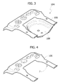
- figure 3 is a perspective view of a portion of floor panel used in the method according to the present invention;
- figure 4 is similar to figure 3, and shows a blank obtained from the portion of floor panel in figure 3, according to a step in the method according to the present invention;
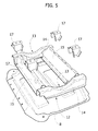
- figure 5 is a perspective view of a further step in the method according to the present invention; and
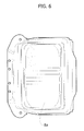
- figures 6 and 7 are respectively a view from above and a lateral view of a variant of the illustration in figure 5.
- In figures 1 and 2, 1 indicates as a whole a motor vehicle (partially illustrated) comprising a frame or unitised body, comprising for example a pair of
longitudinal side members 2. The motor vehicle also comprises a platform orfloor panel 3, which is secured to theside members 2, for example by means of welding, and comprises arear portion 4 which defines the lower support part of a boot 5 (figure 2) which is designed to accommodate luggage. - The portion of
floor panel 4 comprises anattachment portion 6 which is secured directly to theside members 2, and has a form in plan view substantially in the shape of a U, in order to define a through opening 7. The portion offloor panel 4 also comprises anindented support portion 8 which defines a part which is separate from theportion 6, and is secured to theportion 6 itself such as to engage theopening 7, and is configured to support a combustible gas cylinder 9. - With reference to figures 2 and 5, a
frame 12 is disposed beneath thesupport portion 8, it is secured to thesupport portion 8, and on the opposite side, it defines aseat 13
which has a shape such as to accommodate partially the cylinder 9. - In particular the
frame 12 comprises twoside members 14 which are spaced from one another and define theseat 13, and twocross members 15 which connect to one another the ends of theside members 14. Thecross members 15 support in a fixed position fourbrackets 17 for securing of retention belts 18 (figure 1) to be wound around the cylinder 9. - Figures 6 and 7 show a variant of the
support portion 8 indicated by thereference number 8a. - The
support portion 8a incorporates in a single piece theseat 13 and thebrackets 17. In other words, thesupport portion 8a defines directly alower seat 13a which is complementary to an upper portion of the cylinder 9, whereas thebelts 18 are secured directly to thesupport portion 8a, for example by means of screws. - With reference to figures 3 and 4, the portion of
floor panel 4 is produced from a portion offloor panel 104 which defines a sheet metal component from normal production, for example for a motor vehicle which is already commercially available, the engine of which is supplied with petrol or diesel. - The portion of
floor panel 104 is in a single piece and comprises anattachment portion 106 which coincides with theportion 6, and asupport portion 108 which is different
from theportion 8, and defines a seat 113 to accommodate a spare wheel (not illustrated). - In order to produce the portion of
floor panel 4, firstly thesupport portion 108 is removed from theportion 106, for example by means of laser cutting, thus forming theopening 7 and providing the blank shown in figure 4. Theportion portion 108. - For example, the
portion portion 106 by means of welding, after having been positioned in a specific reference position. - In particular, the
support portion - According to one alternative, the
support portion 8a is made of a thermoplastic material reinforced with glass fibres, for example by means of injection moulding. In this case, thesupport portion 8a is secured to theportion 106 by means of gluing. - The
seat 13a is formed directly in thesupport portion 8a during the moulding. - On the other hand, for the solution in figures 2 and 5, the
frame 12, with thebrackets 17, is secured to thesupport portion 8, for example by means of welding, preferably
before the securing of thesupport portion 8 on theportion 106. - Finally, the
belts 18 are coupled in a fixed position on the portion offloor panel 4, or directly on thesupport portion 8a, or indirectly on thesupport portion 8, such as to be able to wind thebelts 18 themselves around the cylinder 9, when the cylinder 9 must then be fitted on themotor vehicle 1 along the production line. - In particular, during the manufacture of the motor vehicles, there are available along the production line both portions of
floor panel 4 and portions offloor panel 104. As is shown from the foregoing description, these portions offloor panel side members 2 as an alternative to one another. Thus, along the production line, if the motor vehicles must be equipped with an engine which is supplied with petrol or diesel, a portion offloor panel 104 is fitted. On the other hand, if the motor vehicles must be equipped with an engine which is supplied with gas, the portion offloor panel 4 is fitted, thus providing for example the embodiment shown in figure 1. - It is apparent from the foregoing description that the method described with reference to the attached figures makes it possible to equip the motor vehicle with a relatively large cylinder 9, without limiting excessively the space in the
boot 5, without modifying theside members 2, and altering only minimally the normal production platform which comprises the portion offloor panel 104. - In particular, the above described method makes it possible to obtain a modular system to equip motor vehicles: in fact, along the production line, the portions of
floor panel platform 3. - Finally, it is apparent from the foregoing description that modifications and variations which do not depart from the field of protection of the present invention can be made to the method described with reference to the attached figures.
- In particular, the
portions platform 3, instead of to theside members 2; and/or they could have a shape which differs slightly from one another, but always having the same points and systems of attachment so as to be fitted as an alternative to one another or interchangeably, in order to complete theplatform 3. - The selection of the portions of
floor panel floor panel
Claims (18)
- Method for the manufacture of motor vehicles, characterised by selection of a portion of floor panel, from amongst a first and a second portion of floor panel available along the production line; the said first and second portions of floor panel comprising:- respectively a first and a second attachment portion which are substantially the same as one another and can be coupled to a frame or support body of a motor vehicle as an alternative to one another;- respectively a first and a second support portion which are different from one another and are secured to the corresponding attachment portions; the first support portion defining a seat to accommodate a spare wheel; the second support portion being configured such as to support a combustible gas cylinder.
- Method according to claim 1, characterised in that the said first portion of floor panel is produced in a single piece, and defines part of a motor vehicle from normal production supplied with fuel other than gas.
- Method according to claim 1 or claim 2, characterised in that the said second attachment portion is a part separate from the said second support portion, and defines a through opening which is engaged by the said second support portion.
- Method according to claim 3, characterised in that the said second portion of floor panel is produced from a further first portion of floor panel which is identical to the said first portion of floor panel.
- Method according to claim 4, characterised in that it comprises the steps of removing the first support portion from the said further first portion of floor panel, and of securing the said second support portion in the place of the first support portion removed.
- Method according to any one of the preceding claims, characterised in that the said second support portion is made of metal material.
- Method according to any one of claims 1 to 5, characterised in that the said second support portion is made of thermoplastic material reinforced with glass fibres.
- Method according to any one of the preceding claims, characterised in that a retention belt is coupled in a position which is fixed relative to the said second support portion, such as to be able to wind the said retention belt around the said combustible gas cylinder.
- Method according to claim 8, characterised in that the said retention belt is secured directly onto the said second support portion.
- Method according to any one of the preceding claims, characterised in that in the said second support portion, there is formed directly a seat which has a shape such as to accommodate partially the said combustible gas cylinder.
- Method according to claim 8, characterised in that a frame is secured to the said second support portion; the said frame defining a seat which has a shape such as to accommodate partially the said combustible gas cylinder, and bearing attachment means for the said retention belt.
- Support module for a combustible gas cylinder, in particular in order to implement the method defined by claim 3, characterised in that it comprises a portion of floor panel which can define a boot of a motor vehicle, and comprising:- an attachment portion which can be coupled to a frame or body of a motor vehicle; and- a support portion which is fixed relative to the said attachment portion and is configured such as to carry a combustible gas cylinder;the said attachment portion being a part which is separate from the said support portion, and defining a through opening which is engaged by the said support portion.
- Module according to claim 12, characterised in that the said support portion is made of metal material.
- Support module according to claim 12, characterised in that the said support portion is made of thermoplastic material reinforced with glass fibres.
- Support module according to any one of claims 12 to 14, characterised in that it comprises a retention belt which is coupled in a position which is fixed relative to the said support portion, such as to be able to wind the said retention belt around the said combustible gas cylinder.
- Support module according to claim 15, characterised in that the said retention belt is secured directly to the said support portion.
- Support module according to any one of claims 12 to 16, characterised in that the said support portion defines directly a seat with a shape such as to accommodate partially the said combustible gas cylinder.
- Support module according to claim 15, characterised in that it additionally comprises a frame which is secured to the said support portion, defining a seat which has a shape such as to accommodate partially the said combustible gas cylinder, and bearing attachment means for the said retention belt.
Applications Claiming Priority (1)
| Application Number | Priority Date | Filing Date | Title |
|---|---|---|---|
| IT000227A ITTO20060227A1 (en) | 2006-03-28 | 2006-03-28 | METHOD FOR THE REALIZATION OF MOTOR VEHICLES, AND MODULE OF SUPPORTING A COMBUSTIBLE GAS CYLINDER TO IMPLEMENT THIS METHOD |
Publications (2)
| Publication Number | Publication Date |
|---|---|
| EP1839926A1 true EP1839926A1 (en) | 2007-10-03 |
| EP1839926B1 EP1839926B1 (en) | 2009-02-18 |
Family
ID=36579098
Family Applications (1)
| Application Number | Title | Priority Date | Filing Date |
|---|---|---|---|
| EP07104925A Active EP1839926B1 (en) | 2006-03-28 | 2007-03-26 | Method for the manufacture of motor vehicles, and module for support of a combustible gas cylinder for implementation of this method |
Country Status (4)
| Country | Link |
|---|---|
| EP (1) | EP1839926B1 (en) |
| AT (1) | ATE423034T1 (en) |
| DE (1) | DE602007000548D1 (en) |
| IT (1) | ITTO20060227A1 (en) |
Cited By (5)
| Publication number | Priority date | Publication date | Assignee | Title |
|---|---|---|---|---|
| FR2933046A1 (en) * | 2008-06-25 | 2010-01-01 | Peugeot Citroen Automobiles Sa | Floor and gas bottle assembly for e.g. car, has gas bottles extended along longitudinal axes, where orthogonal projection of one of axes forms straight line that is inclined to specific angle with respect to central axis of floor |
| WO2012084083A1 (en) | 2010-12-23 | 2012-06-28 | Daimler Ag | Floor module for a motor vehicle with a variable driving concept |
| CN103656905A (en) * | 2012-09-19 | 2014-03-26 | 德拉格安全股份两合公司 | Pressurized gas cylinder holder for a respirator |
| JP2017088017A (en) * | 2015-11-12 | 2017-05-25 | トヨタ自動車株式会社 | vehicle |
| JP2017149316A (en) * | 2016-02-25 | 2017-08-31 | トヨタ自動車株式会社 | Fuel cell vehicle |
Citations (5)
| Publication number | Priority date | Publication date | Assignee | Title |
|---|---|---|---|---|
| US5518272A (en) | 1993-12-28 | 1996-05-21 | Honda Giken Kogyo Kabushiki Kaisha | Fuel bomb mounting structure for automobile |
| JPH09290650A (en) * | 1996-04-26 | 1997-11-11 | Honda Motor Co Ltd | Fuel cylinder fixing structure for automobile and its fixing method |
| JP2000343958A (en) * | 1999-06-02 | 2000-12-12 | Suzuki Motor Corp | Automotive gas container protection device |
| JP2003205754A (en) * | 2002-01-11 | 2003-07-22 | Nissan Motor Co Ltd | Vehicle mounting structure of fuel container |
| US20030189334A1 (en) | 2002-04-08 | 2003-10-09 | Honda Giken Kogyo Kabushiki Kaisha | Vehicle body structure |
-
2006
- 2006-03-28 IT IT000227A patent/ITTO20060227A1/en unknown
-
2007
- 2007-03-26 DE DE602007000548T patent/DE602007000548D1/en active Active
- 2007-03-26 EP EP07104925A patent/EP1839926B1/en active Active
- 2007-03-26 AT AT07104925T patent/ATE423034T1/en not_active IP Right Cessation
Patent Citations (5)
| Publication number | Priority date | Publication date | Assignee | Title |
|---|---|---|---|---|
| US5518272A (en) | 1993-12-28 | 1996-05-21 | Honda Giken Kogyo Kabushiki Kaisha | Fuel bomb mounting structure for automobile |
| JPH09290650A (en) * | 1996-04-26 | 1997-11-11 | Honda Motor Co Ltd | Fuel cylinder fixing structure for automobile and its fixing method |
| JP2000343958A (en) * | 1999-06-02 | 2000-12-12 | Suzuki Motor Corp | Automotive gas container protection device |
| JP2003205754A (en) * | 2002-01-11 | 2003-07-22 | Nissan Motor Co Ltd | Vehicle mounting structure of fuel container |
| US20030189334A1 (en) | 2002-04-08 | 2003-10-09 | Honda Giken Kogyo Kabushiki Kaisha | Vehicle body structure |
Cited By (9)
| Publication number | Priority date | Publication date | Assignee | Title |
|---|---|---|---|---|
| FR2933046A1 (en) * | 2008-06-25 | 2010-01-01 | Peugeot Citroen Automobiles Sa | Floor and gas bottle assembly for e.g. car, has gas bottles extended along longitudinal axes, where orthogonal projection of one of axes forms straight line that is inclined to specific angle with respect to central axis of floor |
| WO2012084083A1 (en) | 2010-12-23 | 2012-06-28 | Daimler Ag | Floor module for a motor vehicle with a variable driving concept |
| CN103269944A (en) * | 2010-12-23 | 2013-08-28 | 戴姆勒股份公司 | Floor module for a motor vehicle with a variable driving concept |
| US8807631B2 (en) | 2010-12-23 | 2014-08-19 | Daimler Ag | Floor module for a motor vehicle with a variable driving concept |
| CN103269944B (en) * | 2010-12-23 | 2017-02-08 | 戴姆勒股份公司 | Floor module for a motor vehicle with a variable driving concept |
| CN103656905A (en) * | 2012-09-19 | 2014-03-26 | 德拉格安全股份两合公司 | Pressurized gas cylinder holder for a respirator |
| US9630032B2 (en) | 2012-09-19 | 2017-04-25 | Dräger Safety AG & Co. KGaA | Pressurized gas cylinder holder for a respirator |
| JP2017088017A (en) * | 2015-11-12 | 2017-05-25 | トヨタ自動車株式会社 | vehicle |
| JP2017149316A (en) * | 2016-02-25 | 2017-08-31 | トヨタ自動車株式会社 | Fuel cell vehicle |
Also Published As
| Publication number | Publication date |
|---|---|
| ATE423034T1 (en) | 2009-03-15 |
| DE602007000548D1 (en) | 2009-04-02 |
| ITTO20060227A1 (en) | 2007-09-29 |
| EP1839926B1 (en) | 2009-02-18 |
Similar Documents
| Publication | Publication Date | Title |
|---|---|---|
| US6729682B2 (en) | Rear module for a motor vehicle | |
| US9227507B2 (en) | Pneumatic powertrain for an automotive vehicle | |
| EP1839926B1 (en) | Method for the manufacture of motor vehicles, and module for support of a combustible gas cylinder for implementation of this method | |
| US20100078254A1 (en) | Body for pneumatic vehicle | |
| US10279853B2 (en) | Method for replacing a roll cage of an off-road vehicle | |
| US8313121B2 (en) | Chassis for pneumatic vehicle | |
| CN101073986B (en) | Intagred automobile bar and upper condensator, radiator and fan module support | |
| US20100102538A1 (en) | Method for illuminating colors in a backlit driver airbag emblem | |
| CN114269637B (en) | motor vehicle unit | |
| AU2009295555A1 (en) | Pneumatic vehicle | |
| US10843602B2 (en) | Seat for vehicles having an engagement edge | |
| US20130001929A1 (en) | Air bag chute topper system | |
| CN101541624B (en) | Vehicle reinforcing structure | |
| US7625037B2 (en) | Vehicle body panel access feature | |
| CN102029960A (en) | Bumper for motor vehicle | |
| SE541974C2 (en) | Battery fastening system and method | |
| CA2973365A1 (en) | Clamp for clamping a windshield to a frame of a vehicle | |
| US20090295195A1 (en) | Car frame featuring rtm-technology modules of compsite material | |
| EP1552986B1 (en) | Support structure for an interior overhead console of panoramic roofs of automotive vehicles | |
| US7384061B2 (en) | Trim panel and a method of manufacture | |
| CN103129483B (en) | Motor vehicle jack accommodating structure | |
| US7287614B2 (en) | Engine compartment cover | |
| WO2005085660A3 (en) | System for fastening a component to a motor vehicle fuel tank, fuel system and method of manufacturing thereof | |
| EP3594093A1 (en) | A motor vehicle floor assembly | |
| EP1172256A3 (en) | Airbag assembly module and method for assembly thereof |
Legal Events
| Date | Code | Title | Description |
|---|---|---|---|
| PUAI | Public reference made under article 153(3) epc to a published international application that has entered the european phase |
Free format text: ORIGINAL CODE: 0009012 |
|
| 17P | Request for examination filed |
Effective date: 20070326 |
|
| AK | Designated contracting states |
Kind code of ref document: A1 Designated state(s): AT BE BG CH CY CZ DE DK EE ES FI FR GB GR HU IE IS IT LI LT LU LV MC MT NL PL PT RO SE SI SK TR |
|
| AX | Request for extension of the european patent |
Extension state: AL BA HR MK YU |
|
| AKX | Designation fees paid |
Designated state(s): AT BE BG CH CY CZ DE DK EE ES FI FR GB GR HU IE IS IT LI LT LU LV MC MT NL PL PT RO SE SI SK TR |
|
| GRAP | Despatch of communication of intention to grant a patent |
Free format text: ORIGINAL CODE: EPIDOSNIGR1 |
|
| GRAS | Grant fee paid |
Free format text: ORIGINAL CODE: EPIDOSNIGR3 |
|
| GRAA | (expected) grant |
Free format text: ORIGINAL CODE: 0009210 |
|
| AK | Designated contracting states |
Kind code of ref document: B1 Designated state(s): AT BE BG CH CY CZ DE DK EE ES FI FR GB GR HU IE IS IT LI LT LU LV MC MT NL PL PT RO SE SI SK TR |
|
| REG | Reference to a national code |
Ref country code: GB Ref legal event code: FG4D |
|
| REG | Reference to a national code |
Ref country code: CH Ref legal event code: EP |
|
| REG | Reference to a national code |
Ref country code: IE Ref legal event code: FG4D |
|
| REF | Corresponds to: |
Ref document number: 602007000548 Country of ref document: DE Date of ref document: 20090402 Kind code of ref document: P |
|
| PG25 | Lapsed in a contracting state [announced via postgrant information from national office to epo] |
Ref country code: NL Free format text: LAPSE BECAUSE OF FAILURE TO SUBMIT A TRANSLATION OF THE DESCRIPTION OR TO PAY THE FEE WITHIN THE PRESCRIBED TIME-LIMIT Effective date: 20090218 Ref country code: LT Free format text: LAPSE BECAUSE OF FAILURE TO SUBMIT A TRANSLATION OF THE DESCRIPTION OR TO PAY THE FEE WITHIN THE PRESCRIBED TIME-LIMIT Effective date: 20090218 Ref country code: ES Free format text: LAPSE BECAUSE OF FAILURE TO SUBMIT A TRANSLATION OF THE DESCRIPTION OR TO PAY THE FEE WITHIN THE PRESCRIBED TIME-LIMIT Effective date: 20090529 Ref country code: SI Free format text: LAPSE BECAUSE OF FAILURE TO SUBMIT A TRANSLATION OF THE DESCRIPTION OR TO PAY THE FEE WITHIN THE PRESCRIBED TIME-LIMIT Effective date: 20090218 Ref country code: FI Free format text: LAPSE BECAUSE OF FAILURE TO SUBMIT A TRANSLATION OF THE DESCRIPTION OR TO PAY THE FEE WITHIN THE PRESCRIBED TIME-LIMIT Effective date: 20090218 |
|
| NLV1 | Nl: lapsed or annulled due to failure to fulfill the requirements of art. 29p and 29m of the patents act | ||
| PG25 | Lapsed in a contracting state [announced via postgrant information from national office to epo] |
Ref country code: LV Free format text: LAPSE BECAUSE OF FAILURE TO SUBMIT A TRANSLATION OF THE DESCRIPTION OR TO PAY THE FEE WITHIN THE PRESCRIBED TIME-LIMIT Effective date: 20090218 Ref country code: AT Free format text: LAPSE BECAUSE OF FAILURE TO SUBMIT A TRANSLATION OF THE DESCRIPTION OR TO PAY THE FEE WITHIN THE PRESCRIBED TIME-LIMIT Effective date: 20090218 Ref country code: PL Free format text: LAPSE BECAUSE OF FAILURE TO SUBMIT A TRANSLATION OF THE DESCRIPTION OR TO PAY THE FEE WITHIN THE PRESCRIBED TIME-LIMIT Effective date: 20090218 Ref country code: SE Free format text: LAPSE BECAUSE OF FAILURE TO SUBMIT A TRANSLATION OF THE DESCRIPTION OR TO PAY THE FEE WITHIN THE PRESCRIBED TIME-LIMIT Effective date: 20090518 Ref country code: IS Free format text: LAPSE BECAUSE OF FAILURE TO SUBMIT A TRANSLATION OF THE DESCRIPTION OR TO PAY THE FEE WITHIN THE PRESCRIBED TIME-LIMIT Effective date: 20090618 |
|
| PG25 | Lapsed in a contracting state [announced via postgrant information from national office to epo] |
Ref country code: BE Free format text: LAPSE BECAUSE OF FAILURE TO SUBMIT A TRANSLATION OF THE DESCRIPTION OR TO PAY THE FEE WITHIN THE PRESCRIBED TIME-LIMIT Effective date: 20090218 |
|
| PG25 | Lapsed in a contracting state [announced via postgrant information from national office to epo] |
Ref country code: PT Free format text: LAPSE BECAUSE OF FAILURE TO SUBMIT A TRANSLATION OF THE DESCRIPTION OR TO PAY THE FEE WITHIN THE PRESCRIBED TIME-LIMIT Effective date: 20090727 Ref country code: MC Free format text: LAPSE BECAUSE OF NON-PAYMENT OF DUE FEES Effective date: 20090331 Ref country code: EE Free format text: LAPSE BECAUSE OF FAILURE TO SUBMIT A TRANSLATION OF THE DESCRIPTION OR TO PAY THE FEE WITHIN THE PRESCRIBED TIME-LIMIT Effective date: 20090218 Ref country code: DK Free format text: LAPSE BECAUSE OF FAILURE TO SUBMIT A TRANSLATION OF THE DESCRIPTION OR TO PAY THE FEE WITHIN THE PRESCRIBED TIME-LIMIT Effective date: 20090218 Ref country code: CZ Free format text: LAPSE BECAUSE OF FAILURE TO SUBMIT A TRANSLATION OF THE DESCRIPTION OR TO PAY THE FEE WITHIN THE PRESCRIBED TIME-LIMIT Effective date: 20090218 |
|
| PG25 | Lapsed in a contracting state [announced via postgrant information from national office to epo] |
Ref country code: SK Free format text: LAPSE BECAUSE OF FAILURE TO SUBMIT A TRANSLATION OF THE DESCRIPTION OR TO PAY THE FEE WITHIN THE PRESCRIBED TIME-LIMIT Effective date: 20090218 Ref country code: RO Free format text: LAPSE BECAUSE OF FAILURE TO SUBMIT A TRANSLATION OF THE DESCRIPTION OR TO PAY THE FEE WITHIN THE PRESCRIBED TIME-LIMIT Effective date: 20090218 |
|
| PLBE | No opposition filed within time limit |
Free format text: ORIGINAL CODE: 0009261 |
|
| STAA | Information on the status of an ep patent application or granted ep patent |
Free format text: STATUS: NO OPPOSITION FILED WITHIN TIME LIMIT |
|
| REG | Reference to a national code |
Ref country code: IE Ref legal event code: MM4A |
|
| 26N | No opposition filed |
Effective date: 20091119 |
|
| PG25 | Lapsed in a contracting state [announced via postgrant information from national office to epo] |
Ref country code: BG Free format text: LAPSE BECAUSE OF FAILURE TO SUBMIT A TRANSLATION OF THE DESCRIPTION OR TO PAY THE FEE WITHIN THE PRESCRIBED TIME-LIMIT Effective date: 20090518 Ref country code: IE Free format text: LAPSE BECAUSE OF NON-PAYMENT OF DUE FEES Effective date: 20090326 |
|
| PG25 | Lapsed in a contracting state [announced via postgrant information from national office to epo] |
Ref country code: GR Free format text: LAPSE BECAUSE OF FAILURE TO SUBMIT A TRANSLATION OF THE DESCRIPTION OR TO PAY THE FEE WITHIN THE PRESCRIBED TIME-LIMIT Effective date: 20090519 |
|
| PG25 | Lapsed in a contracting state [announced via postgrant information from national office to epo] |
Ref country code: IT Free format text: LAPSE BECAUSE OF NON-PAYMENT OF DUE FEES Effective date: 20100326 |
|
| PG25 | Lapsed in a contracting state [announced via postgrant information from national office to epo] |
Ref country code: LU Free format text: LAPSE BECAUSE OF NON-PAYMENT OF DUE FEES Effective date: 20090326 |
|
| PG25 | Lapsed in a contracting state [announced via postgrant information from national office to epo] |
Ref country code: HU Free format text: LAPSE BECAUSE OF FAILURE TO SUBMIT A TRANSLATION OF THE DESCRIPTION OR TO PAY THE FEE WITHIN THE PRESCRIBED TIME-LIMIT Effective date: 20090819 |
|
| PG25 | Lapsed in a contracting state [announced via postgrant information from national office to epo] |
Ref country code: TR Free format text: LAPSE BECAUSE OF FAILURE TO SUBMIT A TRANSLATION OF THE DESCRIPTION OR TO PAY THE FEE WITHIN THE PRESCRIBED TIME-LIMIT Effective date: 20090218 |
|
| PG25 | Lapsed in a contracting state [announced via postgrant information from national office to epo] |
Ref country code: CY Free format text: LAPSE BECAUSE OF FAILURE TO SUBMIT A TRANSLATION OF THE DESCRIPTION OR TO PAY THE FEE WITHIN THE PRESCRIBED TIME-LIMIT Effective date: 20090218 |
|
| REG | Reference to a national code |
Ref country code: CH Ref legal event code: PL |
|
| GBPC | Gb: european patent ceased through non-payment of renewal fee |
Effective date: 20110326 |
|
| PG25 | Lapsed in a contracting state [announced via postgrant information from national office to epo] |
Ref country code: CH Free format text: LAPSE BECAUSE OF NON-PAYMENT OF DUE FEES Effective date: 20110331 Ref country code: LI Free format text: LAPSE BECAUSE OF NON-PAYMENT OF DUE FEES Effective date: 20110331 |
|
| PG25 | Lapsed in a contracting state [announced via postgrant information from national office to epo] |
Ref country code: GB Free format text: LAPSE BECAUSE OF NON-PAYMENT OF DUE FEES Effective date: 20110326 |
|
| REG | Reference to a national code |
Ref country code: DE Ref legal event code: R082 Ref document number: 602007000548 Country of ref document: DE Representative=s name: DR. RALF KOTITSCHKE, DE Ref country code: DE Ref legal event code: R082 Ref document number: 602007000548 Country of ref document: DE Representative=s name: KOTITSCHKE & HEURUNG PARTNERSCHAFT MBB PATENT-, DE |
|
| REG | Reference to a national code |
Ref country code: FR Ref legal event code: PLFP Year of fee payment: 10 |
|
| REG | Reference to a national code |
Ref country code: FR Ref legal event code: PLFP Year of fee payment: 11 |
|
| REG | Reference to a national code |
Ref country code: FR Ref legal event code: PLFP Year of fee payment: 12 |
|
| PGFP | Annual fee paid to national office [announced via postgrant information from national office to epo] |
Ref country code: FR Payment date: 20210326 Year of fee payment: 15 |
|
| PGFP | Annual fee paid to national office [announced via postgrant information from national office to epo] |
Ref country code: DE Payment date: 20210329 Year of fee payment: 15 |
|
| REG | Reference to a national code |
Ref country code: DE Ref legal event code: R119 Ref document number: 602007000548 Country of ref document: DE |
|
| PG25 | Lapsed in a contracting state [announced via postgrant information from national office to epo] |
Ref country code: FR Free format text: LAPSE BECAUSE OF NON-PAYMENT OF DUE FEES Effective date: 20220331 Ref country code: DE Free format text: LAPSE BECAUSE OF NON-PAYMENT OF DUE FEES Effective date: 20221001 |
|
| PGFP | Annual fee paid to national office [announced via postgrant information from national office to epo] |
Ref country code: IT Payment date: 20240220 Year of fee payment: 18 |