EP1839761A1 - Method and apparatus for cleaning painting equipment - Google Patents
Method and apparatus for cleaning painting equipment Download PDFInfo
- Publication number
- EP1839761A1 EP1839761A1 EP06006684A EP06006684A EP1839761A1 EP 1839761 A1 EP1839761 A1 EP 1839761A1 EP 06006684 A EP06006684 A EP 06006684A EP 06006684 A EP06006684 A EP 06006684A EP 1839761 A1 EP1839761 A1 EP 1839761A1
- Authority
- EP
- European Patent Office
- Prior art keywords
- cleaning agent
- under pressure
- gas under
- cleaning
- coating equipment
- Prior art date
- Legal status (The legal status is an assumption and is not a legal conclusion. Google has not performed a legal analysis and makes no representation as to the accuracy of the status listed.)
- Granted
Links
- 238000004140 cleaning Methods 0.000 title claims abstract description 36
- 238000010422 painting Methods 0.000 title claims abstract description 34
- 238000000034 method Methods 0.000 title claims description 28
- 239000012459 cleaning agent Substances 0.000 claims abstract description 87
- 239000011248 coating agent Substances 0.000 claims abstract description 43
- 238000000576 coating method Methods 0.000 claims abstract description 43
- 239000003973 paint Substances 0.000 claims description 14
- 238000011010 flushing procedure Methods 0.000 claims description 9
- 238000010926 purge Methods 0.000 claims description 8
- 239000007921 spray Substances 0.000 claims description 6
- 238000009987 spinning Methods 0.000 claims description 4
- 239000012530 fluid Substances 0.000 claims description 3
- 239000007789 gas Substances 0.000 claims 23
- IJGRMHOSHXDMSA-UHFFFAOYSA-N Atomic nitrogen Chemical compound N#N IJGRMHOSHXDMSA-UHFFFAOYSA-N 0.000 claims 2
- 238000004590 computer program Methods 0.000 claims 1
- 230000001351 cycling effect Effects 0.000 claims 1
- 229910052757 nitrogen Inorganic materials 0.000 claims 1
- 239000002904 solvent Substances 0.000 description 8
- 239000002245 particle Substances 0.000 description 2
- 239000003086 colorant Substances 0.000 description 1
- 230000001419 dependent effect Effects 0.000 description 1
- 238000010586 diagram Methods 0.000 description 1
- 230000000694 effects Effects 0.000 description 1
- 229920006395 saturated elastomer Polymers 0.000 description 1
- 238000007592 spray painting technique Methods 0.000 description 1
- 238000005507 spraying Methods 0.000 description 1
Images


Classifications
-
- B—PERFORMING OPERATIONS; TRANSPORTING
- B05—SPRAYING OR ATOMISING IN GENERAL; APPLYING FLUENT MATERIALS TO SURFACES, IN GENERAL
- B05B—SPRAYING APPARATUS; ATOMISING APPARATUS; NOZZLES
- B05B15/00—Details of spraying plant or spraying apparatus not otherwise provided for; Accessories
- B05B15/50—Arrangements for cleaning; Arrangements for preventing deposits, drying-out or blockage; Arrangements for detecting improper discharge caused by the presence of foreign matter
- B05B15/55—Arrangements for cleaning; Arrangements for preventing deposits, drying-out or blockage; Arrangements for detecting improper discharge caused by the presence of foreign matter using cleaning fluids
Definitions
- the present invention relates to an apparatus and a method for cleaning automated painting or coating equipment with the aid of a gas under pressure and a cleaning agent.
- areas where the present invention can be used are spray paint systems for industrial products, machine parts, appliances, boats or furniture.
- the invention is especially useful for spray paint systems that need to change paint color often, one example would be the spray painting of automobile bodies
- US 5,072,881 suggests mixing solvent and air via an adjustable ratio mixing valve which then supplies the mixed air and solvent to the supply system.
- US 4,881,563 entitled Paint color change system, suggest that between paint color changes, the cleaning solvent is added continuously to the high pressure air in an atomized state and then propelled through the supply line at a high velocity which cleans the supply line thoroughly, permitting a paint color change. It is believed that the improved cleaning occurs because of the finely atomized particles of solvent being carried at high velocity through the supply line and producing a scrub action against the inner walls of the supply line.
- An object of a preferred embodiment of the present invention is to provide an improved method and system whereby cleaning time may be reduced, cleaning efficiency may be increased, amount of cleaning medium needed for cleaning automated painting or coating equipment may be reduce and thereby costs are saved.
- One or more objects are achieved by time-variable release of a cleaning agent into a gas under pressure which is flowing through, at least, parts of an automated painting or coating system.
- the time variable adding will create pulses of cleaning agent saturated gas.
- the gas flow with varying cleaning media saturation and atomized cleaning agent particles cleans the paint color change system, pump, supply line, valve, regulator, applicator or spray gun efficiently.
- the time-variable adding of cleaning agent into the coating system or parts of the coating system is produced by a valve means, preferably a rotating disk, with an opening, which interrupts the cleaning agent feed. When the opening in the rotating disk is aligned with the cleaning agent feed, the cleaning agent is for a short time free to flow and is injected into the flushing gas under pressure.
- the frequency of the pulses is controlled the speed of the disk as well as the number of openings in the disk.
- the dose is dependent on the size of the opening(s) as well as the speed of the disk and the pressure difference between the cleaning agent and the gas under pressure used for flushing the equipment.
- the driving force for the rotation of the disk or other valve means may be provided by a turbine in the compressed gas used for flushing the system or by an engine driven by; pressurized air, electric motor or by an actuator.
- an improved apparatus for cleaning one or more parts of an automated painting or coating equipment comprising a supply of a first gas under pressure, a supply of a cleaning agent, a mixing means for adding the cleaning agent to the said gas under pressure and supplying it to at least a part of said automated painting or coating equipment wherein said mixing means is adapted to release said cleaning agent into said first gas under pressure such that the amount of said cleaning agent released is variable with time.
- an improved apparatus for cleaning one or more parts of an automated painting or coating equipment wherein the released amount of said cleaning agent cycles between a maximum flow and a minimum or zero flow.
- an improved apparatus for cleaning one or more parts of an automated painting or coating equipment wherein the cleaning agent is released as a number of pulses into said first gas under pressure.
- an improved apparatus for cleaning one or more parts of an automated painting or coating equipment wherein said mixing means comprises a valve means arranged to control the flow and amount of said cleaning agent said first gas under pressure.
- valve means comprises a rotatable disk provided with at least one opening arranged to turn on or turn off said cleaning agent supply by rotation of the rotatable disk.
- an improved apparatus for cleaning one or more parts of an automated painting or coating equipment wherein rotation of said rotatable disk is driven by said first gas under pressure or a second gas under pressure.
- an improved apparatus for cleaning one or more parts of an automated painting or coating equipment wherein the rotational speed of said rotatable disk is arranged variable so as to control the frequency of cleaning agent pulses.
- an improved method for cleaning one or more parts of an automated painting or coating equipment wherein the amount of said cleaning agent released into said first gas under pressure varies with time.
- an improved method for cleaning one or more parts of an automated painting or coating equipment wherein the time variant release of said cleaning agent into said stream of gas under pressure is achieved by injecting pulses of cleaning agent.
- an improved method for cleaning one or more parts of an automated painting or coating equipment wherein flushing or purging at least part of the said automated painting or coating equipment by releasing the said first gas under pressure during a period of time in which the amount of cleaning agent added is zero.
- an improved method for cleaning one or more parts of an automated painting or coating equipment wherein by beginning or ending a cleaning process by purging the said automated painting or coating equipment with said first gas under pressure without any said cleaning agent.
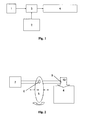
- Fig. 1 illustrates a gas supply 1 with gas under pressure which is connected to the mixing means 3.
- a cleaning agent supply 2 is connected to a mixing means 3.
- the mixing means 3 doses and releases the cleaning agent from the cleaning agent supply 2 into gas under pressure from the gas supply 1.
- the gas with time varying amount of cleaning agent is supplied into at least a part of the automated painting or coating equipment 4.
- the automated painting or coating equipment 4 may be any type of equipment normally found in a painting or coating system such as; paint color change system, pump, supply line, valve, regulator, applicator or spray gun, which needs cleaning.
- Fig. 2 illustrates the mixing means 3 where a rotating disk 5 periodically interrupts the cleaning agent from the cleaning agent supply 2.
- the rotating disk 5 has an opening 6.
- the opening 6, due to the rotation of the disk, is aligned with the cleaning agent feed, the cleaning agent flow is no longer interrupted and this allows a short pulse of cleaning agent to be injected into 9 the gas flow 10 which is flushed into at least a part of the automated painting or coating equipment 4.
- Fig. 3 illustrates a schematic part of the rotation of the rotational disk.
- 5a is a snapshot of the disk 5 before the opening 6 in the disk is aligned with the cleaning agent feed 7.
- 5b is a snapshot of the disk 5 as the opening 6 in the disk is aligned with the cleaning agent feed 7.
- 5c is a snapshot of the disk 5 after the opening 6 in the disk has moved, due to the rotation of the disk, away from the cleaning agent feed 7 and thereby interrupting the cleaning agent flow.
- Fig. 3 illustrates how the cleaning agent flow changes with time as the disk 5 rotates.
- the x-axis represents time and the y-axis represents the flow of cleaning agent F CA .
- the disk interrupts the cleaning agent feed (snapshot 5a above illustrates the arrangement of the disk 5, the opening 6 and the feed 7 at the time T- ⁇ t) and the flow of cleaning agent is thus zero.
- the opening 6 begins to be aligned with the cleaning agent feed 7 and the flow of cleaning agent begins and starts to increase.
- T the opening 6 is perfectly aligned with the cleaning agent feed 7 and the flow of cleaning agent is at a maximum 8 level.
- the opening 6 moves away from the cleaning agent feed 7 the flow of cleaning agent starts to decrease.
- T+ ⁇ t the opening 6 has moved away from the cleaning agent feed 7 and the flow of cleaning agent is interrupted and thus zero.
- the rotational speed of the disk 5 determines the frequency of the of the time varying release of cleaning agent.
- Fig. 4 The method of a preferred embodiment is described in Fig. 4 and comprises:
- Fig. 5 The method of a second embodiment is described in Fig. 5 and comprises:
- the apparatus may be equipped with a number of warning systems for incorrect cleaning operation, for example;
Landscapes
- Application Of Or Painting With Fluid Materials (AREA)
- Spray Control Apparatus (AREA)
- Details Or Accessories Of Spraying Plant Or Apparatus (AREA)
- Cleaning By Liquid Or Steam (AREA)
- Coating Apparatus (AREA)
- Nozzles (AREA)
Abstract
Description
- The present invention relates to an apparatus and a method for cleaning automated painting or coating equipment with the aid of a gas under pressure and a cleaning agent. Examples of areas where the present invention can be used are spray paint systems for industrial products, machine parts, appliances, boats or furniture.
The invention is especially useful for spray paint systems that need to change paint color often, one example would be the spray painting of automobile bodies - One commonly used procedure for cleaning automated painting or coating equipment is described in
US 5,072,881 , entitled Method of cleaning automated paint spraying equipment.
When changing from one color to another it is necessary to purge the paint supply lines leading to the applicators or spray guns quickly so as to avoid intermixing of the different colors. This purging operation is accomplished by alternately adding set quantities of air and solvent through the supply lines by opening and closing appropriate air and solvent valves. This process is slow and uses a substantial amount of solvent. - To reduce the time required as well as the amount of solvents used in this operation,
US 5,072,881 suggests mixing solvent and air via an adjustable ratio mixing valve which then supplies the mixed air and solvent to the supply system.
US 4,881,563 , entitled Paint color change system, suggest that between paint color changes, the cleaning solvent is added continuously to the high pressure air in an atomized state and then propelled through the supply line at a high velocity which cleans the supply line thoroughly, permitting a paint color change. It is believed that the improved cleaning occurs because of the finely atomized particles of solvent being carried at high velocity through the supply line and producing a scrub action against the inner walls of the supply line. - An object of a preferred embodiment of the present invention is to provide an improved method and system whereby cleaning time may be reduced, cleaning efficiency may be increased, amount of cleaning medium needed for cleaning automated painting or coating equipment may be reduce and thereby costs are saved.
- One or more objects are achieved by time-variable release of a cleaning agent into a gas under pressure which is flowing through, at least, parts of an automated painting or coating system. The time variable adding will create pulses of cleaning agent saturated gas. The gas flow with varying cleaning media saturation and atomized cleaning agent particles cleans the paint color change system, pump, supply line, valve, regulator, applicator or spray gun efficiently. The time-variable adding of cleaning agent into the coating system or parts of the coating system is produced by a valve means, preferably a rotating disk, with an opening, which interrupts the cleaning agent feed. When the opening in the rotating disk is aligned with the cleaning agent feed, the cleaning agent is for a short time free to flow and is injected into the flushing gas under pressure. When the opening in the disk moves away, by the rotation of the disk, the flow of cleaning agent is interrupted. This creates a time-variable concentration of cleaning agent in the flushing gas.
The frequency of the pulses is controlled the speed of the disk as well as the number of openings in the disk. The dose is dependent on the size of the opening(s) as well as the speed of the disk and the pressure difference between the cleaning agent and the gas under pressure used for flushing the equipment.
The driving force for the rotation of the disk or other valve means may be provided by a turbine in the compressed gas used for flushing the system or by an engine driven by; pressurized air, electric motor or by an actuator. - According to an embodiment of the invention an improved apparatus for cleaning one or more parts of an automated painting or coating equipment is provided, comprising a supply of a first gas under pressure, a supply of a cleaning agent, a mixing means for adding the cleaning agent to the said gas under pressure and supplying it to at least a part of said automated painting or coating equipment wherein said mixing means is adapted to release said cleaning agent into said first gas under pressure such that the amount of said cleaning agent released is variable with time.
- According to another embodiment of the invention an improved apparatus for cleaning one or more parts of an automated painting or coating equipment wherein the released amount of said cleaning agent cycles between a maximum flow and a minimum or zero flow.
- According to another embodiment of the invention an improved apparatus for cleaning one or more parts of an automated painting or coating equipment wherein the cleaning agent is released as a number of pulses into said first gas under pressure.
- According to another embodiment of the invention an improved apparatus for cleaning one or more parts of an automated painting or coating equipment wherein said mixing means comprises a valve means arranged to control the flow and amount of said cleaning agent said first gas under pressure.
- According to another embodiment of the invention an improved apparatus for cleaning one or more parts of an automated painting or coating equipment wherein the valve means comprises a rotatable disk provided with at least one opening arranged to turn on or turn off said cleaning agent supply by rotation of the rotatable disk.
- According to another embodiment of the invention an improved apparatus for cleaning one or more parts of an automated painting or coating equipment wherein rotation of said rotatable disk is driven by said first gas under pressure or a second gas under pressure.
- According to another embodiment of the invention an improved apparatus for cleaning one or more parts of an automated painting or coating equipment wherein the rotational speed of said rotatable disk is arranged variable so as to control the frequency of cleaning agent pulses.
- According to another embodiment of the invention an improved method for cleaning one or more parts of an automated painting or coating equipment wherein the amount of said cleaning agent released into said first gas under pressure varies with time.
- According to another embodiment of the invention an improved method for cleaning one or more parts of an automated painting or coating equipment wherein the time variant release of said cleaning agent into said stream of gas under pressure is achieved by injecting pulses of cleaning agent.
- According to another embodiment of the invention an improved method for cleaning one or more parts of an automated painting or coating equipment wherein flushing or purging at least part of the said automated painting or coating equipment by releasing the said first gas under pressure during a period of time in which the amount of cleaning agent added is zero.
- According to another embodiment of the invention an improved method for cleaning one or more parts of an automated painting or coating equipment wherein by beginning or ending a cleaning process by purging the said automated painting or coating equipment with said first gas under pressure without any said cleaning agent.
- The invention will be elucidated by reference to an embodiment partially illustrated in the drawings.
- Fig. 1 illustrates a schematic flow diagram according to an embodiment of the invention while Fig. 2 illustrates a partial plan of the mixing means according to an embodiment in Fig. 1.
- Fig. 3 illustrates a part of the rotation of the rotational disk and the effect on the cleaning agent flow.
- Fig. 4 is a flowchart for a method according to an embodiment of the invention and Fig. 5 is another flowchart for a method according to another embodiment of the invention.
- Fig. 1 illustrates a
gas supply 1 with gas under pressure which is connected to the mixing means 3. Acleaning agent supply 2 is connected to a mixing means 3. The mixing means 3 doses and releases the cleaning agent from thecleaning agent supply 2 into gas under pressure from thegas supply 1. The gas with time varying amount of cleaning agent is supplied into at least a part of the automated painting orcoating equipment 4. The automated painting orcoating equipment 4 may be any type of equipment normally found in a painting or coating system such as; paint color change system, pump, supply line, valve, regulator, applicator or spray gun, which needs cleaning. - Fig. 2 illustrates the mixing means 3 where a rotating
disk 5 periodically interrupts the cleaning agent from thecleaning agent supply 2. The rotatingdisk 5 has anopening 6. When theopening 6, due to the rotation of the disk, is aligned with the cleaning agent feed, the cleaning agent flow is no longer interrupted and this allows a short pulse of cleaning agent to be injected into 9 thegas flow 10 which is flushed into at least a part of the automated painting orcoating equipment 4. - The top part of Fig. 3 illustrates a schematic part of the rotation of the rotational disk. 5a is a snapshot of the
disk 5 before the opening 6 in the disk is aligned with thecleaning agent feed 7. 5b is a snapshot of thedisk 5 as the opening 6 in the disk is aligned with thecleaning agent feed 7. 5c is a snapshot of thedisk 5 after theopening 6 in the disk has moved, due to the rotation of the disk, away from thecleaning agent feed 7 and thereby interrupting the cleaning agent flow. - The lower part of Fig. 3 illustrates how the cleaning agent flow changes with time as the
disk 5 rotates. The x-axis represents time and the y-axis represents the flow of cleaning agent FCA. At a time, T-Δt, the disk interrupts the cleaning agent feed (snapshot 5a above illustrates the arrangement of thedisk 5, theopening 6 and thefeed 7 at the time T-Δt) and the flow of cleaning agent is thus zero.
At a time between T-Δt and T, theopening 6 begins to be aligned with thecleaning agent feed 7 and the flow of cleaning agent begins and starts to increase.
At a time T theopening 6 is perfectly aligned with thecleaning agent feed 7 and the flow of cleaning agent is at a maximum 8 level. As theopening 6 moves away from the cleaning agent feed 7 the flow of cleaning agent starts to decrease. At the time T+Δt, theopening 6 has moved away from thecleaning agent feed 7 and the flow of cleaning agent is interrupted and thus zero. The rotational speed of thedisk 5 determines the frequency of the of the time varying release of cleaning agent. - The method of a preferred embodiment is described in Fig. 4 and comprises:
- 22 the coating equipment is flushed with gas under pressure to purge remaining paint from the equipment (e.g. by turning on a valve in the supply of the first gas under pressure),
- 24 the disk starts rotating (e.g. by opening a valve in the supply of the second gas under pressure which may drive the disk),
- 26 the cleaning agent feed starts (e.g. by turning on a valve in cleaning agent feed),
- 32 the cleaning agent feed is turned off when the cleaning of the coating equipment is finished,
- 34 the rotation of the disk stops (e.g. by closing the valve for the second gas under pressure which may drive the disk), 36 the flushing of the coating equipment with gas under pressure stops (e.g. by closing the first gas valve),
- 38 the coating equipment is clean.
- The method of a second embodiment is described in Fig. 5 and comprises:
- 22 the coating equipment is flushed with gas under pressure to purge remaining paint from the equipment (e.g. by turning on a valve in the supply of the first gas under pressure),
- 24 the disk starts rotating (e.g. by turning on a valve in the supply of the second gas under pressure which may drive the disk),
- 26 the cleaning agent feed starts (e.g. by turning on a valve in cleaning agent feed),
- 28 the speed of the disk (and thus the frequency of pulses) may be controlled by a control loop acting on e.g. the valve for the second gas under pressure,
- 30 sensors send warning messages to a control system,
- 32 the cleaning agent feed is turned off when the cleaning of the coating equipment is finished,
- 34 the rotation of the disk stops (e.g. by closing the valve for the second gas under pressure which drives the disk),
- 36 the flushing of the coating equipment with gas under pressure stops (e.g. by closing the first gas valve),
- 38 the coating equipment is clean.
- As described in
step 30 in the second embodiment of the invention, the apparatus may be equipped with a number of warning systems for incorrect cleaning operation, for example; - if the pressure of the cleaning fluid falls below a predetermined amount, a pressure transducer generates a warning signal
- if the flow of cleaning fluid falls below a predetermined volume, a flow meter generates a warning signal
- if the disk is not spinning or spinning at the wrong speed, a warning signal is generated.
Claims (26)
- An apparatus for cleaning one or more parts of an automated painting or coating equipment comprising:- a supply of a first gas under pressure,- a supply of a cleaning agent,- a mixing means for adding the cleaning agent to the said gas, and supplying it to at least a part of said automated painting or coating equipment,characterized in that said mixing means is adapted to release said cleaning agent into said first gas under pressure whereby the amount of said cleaning agent released varies with time.
- The apparatus is according to claim 1 characterized in that the released amount of said cleaning agent cycles between a maximum flow and a minimum flow or zero flow.
- The apparatus is according to claim 1 characterized in that said cleaning agent is released as a number of pulses into said first gas under pressure.
- The apparatus according to any of the previous claims characterized in that said mixing means comprises a valve means arranged to control the flow and amount of said cleaning agent said first gas under pressure.
- The apparatus according to claim 4, characterized in that the valve means comprises a rotatable disk provided with at least one opening arranged to turn on or turn off said cleaning agent supply by rotation of the rotatable disk.
- The apparatus according to claim 5, characterized in that rotation of said rotatable disk is driven by said first gas under pressure or a second gas under pressure.
- The apparatus according to claim 6, characterized in that the first or second gas under pressure is pressurised air.
- The apparatus according to claim 5, characterized in that said rotatable disk is driven by a motor or actuator powered by an energy source other than a gas under pressure.
- The apparatus according to claim 5 characterized by that the rotational speed of said rotatable disk is arranged variable so as to control the frequency of cleaning agent pulses.
- The apparatus according to claim 4 characterized in that said mixing means is arranged so that it may be exchanged with another mixing means device.
- The apparatus according to claim 5 characterized in that said rotatable disk in said mixing means may be exchangeable.
- The apparatus according to claim 4 characterized in that said mixing means comprises two or more valve means with a different valve characteristics.
- The apparatus according to any previous claims characterized by that said automated painting or coating equipment apparatus comprises any from the group of: paint color change system, pump, supply line, valve, paint dosing apparatus, regulator, applicator or spray gun.
- The apparatus according any previous claims characterized by comprising one or more warning systems,- a pressure transducers generates a warning signal if the pressure of the cleaning agent pressure falls below a predetermined level,- a flow meter generates a warning signal if the cleaning fluid flow falls below a predetermined volume,- a motion sensor generates a warning signal if the disk is not spinning or spinning at wrong speed.
- A method of cleaning one or more parts of an automated painting or coating equipment by means of an apparatus comprising, a supply of a first gas under pressure, a supply of a cleaning agent, a mixing means for adding the cleaning agent to the said gas under pressure, the method comprising:- flushing at least part of the said automated painting or coating equipment with the first gas under pressure,- adding cleaning agent to said gas under pressure, andcharacterized in that releasing said cleaning agent into said first gas under pressure whereby the amount of said cleaning agent released varies with time.
- The method according to claim 15 where the time variant release of said cleaning agent is achieved by cycling the flow of cleaning agent between maximum flow and a minimum flow into said stream of gas under pressure.
- The method according to claim 15 where the time variant release of said cleaning agent into said stream of gas under pressure is achieved by injecting pulses of cleaning agent.
- The method according to claim 15 where flushing or purging at least part of the said automated painting or coating equipment by releasing the said first gas under pressure during a period of time in which the amount of cleaning agent added is zero.
- The method according to claim 18, by beginning or ending a cleaning process by purging the said automated painting or coating equipment with said first gas under pressure without any said cleaning agent.
- The method according to previous claims where the said gas under pressure comprises of more than 80% nitrogen.
- The method according to previous claims where the said gas under pressure has a relative humidity of less than 50%.
- The method according to previous claims where the said cleaning agent temperature is above 40 C.
- The method according to claim 16 where the of time variant release of said cleaning agent into said first gas under pressure in cycles with a frequency of 5 Hz to 1000 Hz.
- The method according to claim 16 where the of time variant release of said cleaning agent into said first gas under pressure in cycles with a frequency of 10 Hz to 100 Hz.
- A computer program product, directly loadable into the internal memory of a digital computer, comprising software code portions for carrying out a method according to any of the claims 15-24 when said product is run on a computer.
- A system for automated painting or coating equipment comprising an apparatus for cleaning at least a part of said automated painting or coating equipment characterized in that said apparatus comprises a mixing means which is adapted to a time variant release of cleaning agent into a gas under pressure for cleaning a part of said equipment.
Priority Applications (6)
| Application Number | Priority Date | Filing Date | Title |
|---|---|---|---|
| DE602006004169T DE602006004169D1 (en) | 2006-03-30 | 2006-03-30 | Method and device for cleaning paint shops |
| EP06006684A EP1839761B1 (en) | 2006-03-30 | 2006-03-30 | Method and apparatus for cleaning painting equipment |
| AT06006684T ATE416850T1 (en) | 2006-03-30 | 2006-03-30 | METHOD AND DEVICE FOR CLEANING PAINTING SYSTEMS |
| CNA2007101464944A CN101104161A (en) | 2006-03-30 | 2007-03-30 | A device for cleaning painting equipment |
| US11/730,266 US20070246082A1 (en) | 2006-03-30 | 2007-03-30 | Apparatus for cleaning painting equipment |
| JP2007090098A JP2007268528A (en) | 2006-03-30 | 2007-03-30 | Cleaning device of coating facility |
Applications Claiming Priority (1)
| Application Number | Priority Date | Filing Date | Title |
|---|---|---|---|
| EP06006684A EP1839761B1 (en) | 2006-03-30 | 2006-03-30 | Method and apparatus for cleaning painting equipment |
Publications (2)
| Publication Number | Publication Date |
|---|---|
| EP1839761A1 true EP1839761A1 (en) | 2007-10-03 |
| EP1839761B1 EP1839761B1 (en) | 2008-12-10 |
Family
ID=36928610
Family Applications (1)
| Application Number | Title | Priority Date | Filing Date |
|---|---|---|---|
| EP06006684A Expired - Lifetime EP1839761B1 (en) | 2006-03-30 | 2006-03-30 | Method and apparatus for cleaning painting equipment |
Country Status (6)
| Country | Link |
|---|---|
| US (1) | US20070246082A1 (en) |
| EP (1) | EP1839761B1 (en) |
| JP (1) | JP2007268528A (en) |
| CN (1) | CN101104161A (en) |
| AT (1) | ATE416850T1 (en) |
| DE (1) | DE602006004169D1 (en) |
Families Citing this family (2)
| Publication number | Priority date | Publication date | Assignee | Title |
|---|---|---|---|---|
| CN104815777A (en) * | 2015-04-28 | 2015-08-05 | 苏州杰东纺织新材料科技有限公司 | Compound equipment of tourmaline-loaded nanometer TiO2 compound fabrics |
| CN108097642A (en) * | 2017-12-26 | 2018-06-01 | 苏州贝尔纳德铁路设备有限公司 | A kind of Paint removing process of high-speed EMU wheel pair |
Citations (3)
| Publication number | Priority date | Publication date | Assignee | Title |
|---|---|---|---|---|
| US5322571A (en) * | 1992-03-11 | 1994-06-21 | Plummer Design & Technologies, Inc. | Method and apparatus for cleaning hoses |
| US5709749A (en) * | 1994-10-03 | 1998-01-20 | Behr Systems, Inc. | Solvent supply for paint sprayer |
| US6116261A (en) * | 1999-05-13 | 2000-09-12 | Rosen; Paul W. | Solvent and air mixing system with air bleed backflow |
Family Cites Families (2)
| Publication number | Priority date | Publication date | Assignee | Title |
|---|---|---|---|---|
| US4881563A (en) * | 1986-09-05 | 1989-11-21 | General Motors Corporation | Paint color change system |
| US5072881A (en) * | 1990-06-04 | 1991-12-17 | Systems Specialties | Method of cleaning automated paint spraying equipment |
-
2006
- 2006-03-30 EP EP06006684A patent/EP1839761B1/en not_active Expired - Lifetime
- 2006-03-30 DE DE602006004169T patent/DE602006004169D1/en not_active Expired - Lifetime
- 2006-03-30 AT AT06006684T patent/ATE416850T1/en not_active IP Right Cessation
-
2007
- 2007-03-30 US US11/730,266 patent/US20070246082A1/en not_active Abandoned
- 2007-03-30 JP JP2007090098A patent/JP2007268528A/en active Pending
- 2007-03-30 CN CNA2007101464944A patent/CN101104161A/en active Pending
Patent Citations (3)
| Publication number | Priority date | Publication date | Assignee | Title |
|---|---|---|---|---|
| US5322571A (en) * | 1992-03-11 | 1994-06-21 | Plummer Design & Technologies, Inc. | Method and apparatus for cleaning hoses |
| US5709749A (en) * | 1994-10-03 | 1998-01-20 | Behr Systems, Inc. | Solvent supply for paint sprayer |
| US6116261A (en) * | 1999-05-13 | 2000-09-12 | Rosen; Paul W. | Solvent and air mixing system with air bleed backflow |
Also Published As
| Publication number | Publication date |
|---|---|
| US20070246082A1 (en) | 2007-10-25 |
| DE602006004169D1 (en) | 2009-01-22 |
| ATE416850T1 (en) | 2008-12-15 |
| EP1839761B1 (en) | 2008-12-10 |
| JP2007268528A (en) | 2007-10-18 |
| CN101104161A (en) | 2008-01-16 |
Similar Documents
| Publication | Publication Date | Title |
|---|---|---|
| CN101610853B (en) | Automatic tank cleaning and monitoring device | |
| US11440035B2 (en) | Application device and method for applying a multicomponent coating medium | |
| CN107787251B (en) | Spray Tool System | |
| JP7146634B2 (en) | nebulizer system | |
| CN110090770A (en) | For preventing the turnable nozzle of blocking in ultrasonic atomizer | |
| ATE382026T1 (en) | METHOD AND DEVICE FOR FILLING LIQUIDS AND SOLIDS | |
| JPH07251115A (en) | Two-component discharge system | |
| CN103372522A (en) | Robot coating system | |
| JP7686638B2 (en) | Atomizers and related operating methods | |
| JP6848486B2 (en) | apparatus | |
| JP2001518006A (en) | Apparatus for applying multi-component coating compositions | |
| EP1839761B1 (en) | Method and apparatus for cleaning painting equipment | |
| CA2010656C (en) | Method and apparatus for flushing residual paint from the internal flow passages in a paint distribution system | |
| JPS6279865A (en) | Automatic spray gun | |
| JP2000153184A (en) | Coating apparatus and coating method for multicolor coating | |
| JP7488647B2 (en) | Coating method using a multi-component paint coating system | |
| JP6865402B2 (en) | Cleaning method and cleaning equipment | |
| JPH044060A (en) | Method and device for deflecting and distributing liquid or melt flowing out nozzle hole by gas flow ejecting from periphery thereof | |
| JP3216892B2 (en) | Flow control device | |
| JP2007260531A (en) | Discharge paint control system in robot painting | |
| JP4520601B2 (en) | Two-component mixed coating equipment | |
| SU1547858A1 (en) | Automatic painting device | |
| JPH05317782A (en) | Surface coating method and surface coating apparatus using the method | |
| JP2002102751A (en) | Two-component mixed coating equipment | |
| JPH07192B2 (en) | In-tank cleaning method and cleaning device |
Legal Events
| Date | Code | Title | Description |
|---|---|---|---|
| PUAI | Public reference made under article 153(3) epc to a published international application that has entered the european phase |
Free format text: ORIGINAL CODE: 0009012 |
|
| AK | Designated contracting states |
Kind code of ref document: A1 Designated state(s): AT BE BG CH CY CZ DE DK EE ES FI FR GB GR HU IE IS IT LI LT LU LV MC NL PL PT RO SE SI SK TR |
|
| AX | Request for extension of the european patent |
Extension state: AL BA HR MK YU |
|
| 17P | Request for examination filed |
Effective date: 20080312 |
|
| AKX | Designation fees paid |
Designated state(s): AT BE BG CH CY CZ DE DK EE ES FI FR GB GR HU IE IS IT LI LT LU LV MC NL PL PT RO SE SI SK TR |
|
| GRAP | Despatch of communication of intention to grant a patent |
Free format text: ORIGINAL CODE: EPIDOSNIGR1 |
|
| GRAS | Grant fee paid |
Free format text: ORIGINAL CODE: EPIDOSNIGR3 |
|
| GRAA | (expected) grant |
Free format text: ORIGINAL CODE: 0009210 |
|
| AK | Designated contracting states |
Kind code of ref document: B1 Designated state(s): AT BE BG CH CY CZ DE DK EE ES FI FR GB GR HU IE IS IT LI LT LU LV MC NL PL PT RO SE SI SK TR |
|
| REG | Reference to a national code |
Ref country code: GB Ref legal event code: FG4D |
|
| REG | Reference to a national code |
Ref country code: CH Ref legal event code: EP |
|
| REG | Reference to a national code |
Ref country code: IE Ref legal event code: FG4D |
|
| REF | Corresponds to: |
Ref document number: 602006004169 Country of ref document: DE Date of ref document: 20090122 Kind code of ref document: P |
|
| PG25 | Lapsed in a contracting state [announced via postgrant information from national office to epo] |
Ref country code: LT Free format text: LAPSE BECAUSE OF FAILURE TO SUBMIT A TRANSLATION OF THE DESCRIPTION OR TO PAY THE FEE WITHIN THE PRESCRIBED TIME-LIMIT Effective date: 20081210 |
|
| PG25 | Lapsed in a contracting state [announced via postgrant information from national office to epo] |
Ref country code: PL Free format text: LAPSE BECAUSE OF FAILURE TO SUBMIT A TRANSLATION OF THE DESCRIPTION OR TO PAY THE FEE WITHIN THE PRESCRIBED TIME-LIMIT Effective date: 20081210 Ref country code: FI Free format text: LAPSE BECAUSE OF FAILURE TO SUBMIT A TRANSLATION OF THE DESCRIPTION OR TO PAY THE FEE WITHIN THE PRESCRIBED TIME-LIMIT Effective date: 20081210 Ref country code: SI Free format text: LAPSE BECAUSE OF FAILURE TO SUBMIT A TRANSLATION OF THE DESCRIPTION OR TO PAY THE FEE WITHIN THE PRESCRIBED TIME-LIMIT Effective date: 20081210 Ref country code: NL Free format text: LAPSE BECAUSE OF FAILURE TO SUBMIT A TRANSLATION OF THE DESCRIPTION OR TO PAY THE FEE WITHIN THE PRESCRIBED TIME-LIMIT Effective date: 20081210 Ref country code: LV Free format text: LAPSE BECAUSE OF FAILURE TO SUBMIT A TRANSLATION OF THE DESCRIPTION OR TO PAY THE FEE WITHIN THE PRESCRIBED TIME-LIMIT Effective date: 20081210 |
|
| NLV1 | Nl: lapsed or annulled due to failure to fulfill the requirements of art. 29p and 29m of the patents act | ||
| PG25 | Lapsed in a contracting state [announced via postgrant information from national office to epo] |
Ref country code: ES Free format text: LAPSE BECAUSE OF FAILURE TO SUBMIT A TRANSLATION OF THE DESCRIPTION OR TO PAY THE FEE WITHIN THE PRESCRIBED TIME-LIMIT Effective date: 20090321 Ref country code: BE Free format text: LAPSE BECAUSE OF FAILURE TO SUBMIT A TRANSLATION OF THE DESCRIPTION OR TO PAY THE FEE WITHIN THE PRESCRIBED TIME-LIMIT Effective date: 20081210 Ref country code: EE Free format text: LAPSE BECAUSE OF FAILURE TO SUBMIT A TRANSLATION OF THE DESCRIPTION OR TO PAY THE FEE WITHIN THE PRESCRIBED TIME-LIMIT Effective date: 20081210 Ref country code: RO Free format text: LAPSE BECAUSE OF FAILURE TO SUBMIT A TRANSLATION OF THE DESCRIPTION OR TO PAY THE FEE WITHIN THE PRESCRIBED TIME-LIMIT Effective date: 20081210 Ref country code: BG Free format text: LAPSE BECAUSE OF FAILURE TO SUBMIT A TRANSLATION OF THE DESCRIPTION OR TO PAY THE FEE WITHIN THE PRESCRIBED TIME-LIMIT Effective date: 20090310 |
|
| PG25 | Lapsed in a contracting state [announced via postgrant information from national office to epo] |
Ref country code: IS Free format text: LAPSE BECAUSE OF FAILURE TO SUBMIT A TRANSLATION OF THE DESCRIPTION OR TO PAY THE FEE WITHIN THE PRESCRIBED TIME-LIMIT Effective date: 20090410 Ref country code: PT Free format text: LAPSE BECAUSE OF FAILURE TO SUBMIT A TRANSLATION OF THE DESCRIPTION OR TO PAY THE FEE WITHIN THE PRESCRIBED TIME-LIMIT Effective date: 20090511 Ref country code: SE Free format text: LAPSE BECAUSE OF FAILURE TO SUBMIT A TRANSLATION OF THE DESCRIPTION OR TO PAY THE FEE WITHIN THE PRESCRIBED TIME-LIMIT Effective date: 20090310 Ref country code: AT Free format text: LAPSE BECAUSE OF FAILURE TO SUBMIT A TRANSLATION OF THE DESCRIPTION OR TO PAY THE FEE WITHIN THE PRESCRIBED TIME-LIMIT Effective date: 20081210 Ref country code: CZ Free format text: LAPSE BECAUSE OF FAILURE TO SUBMIT A TRANSLATION OF THE DESCRIPTION OR TO PAY THE FEE WITHIN THE PRESCRIBED TIME-LIMIT Effective date: 20081210 |
|
| PG25 | Lapsed in a contracting state [announced via postgrant information from national office to epo] |
Ref country code: SK Free format text: LAPSE BECAUSE OF FAILURE TO SUBMIT A TRANSLATION OF THE DESCRIPTION OR TO PAY THE FEE WITHIN THE PRESCRIBED TIME-LIMIT Effective date: 20081210 |
|
| PLBE | No opposition filed within time limit |
Free format text: ORIGINAL CODE: 0009261 |
|
| STAA | Information on the status of an ep patent application or granted ep patent |
Free format text: STATUS: NO OPPOSITION FILED WITHIN TIME LIMIT |
|
| PG25 | Lapsed in a contracting state [announced via postgrant information from national office to epo] |
Ref country code: DK Free format text: LAPSE BECAUSE OF FAILURE TO SUBMIT A TRANSLATION OF THE DESCRIPTION OR TO PAY THE FEE WITHIN THE PRESCRIBED TIME-LIMIT Effective date: 20081210 Ref country code: MC Free format text: LAPSE BECAUSE OF NON-PAYMENT OF DUE FEES Effective date: 20090331 |
|
| 26N | No opposition filed |
Effective date: 20090911 |
|
| REG | Reference to a national code |
Ref country code: FR Ref legal event code: ST Effective date: 20091130 |
|
| PG25 | Lapsed in a contracting state [announced via postgrant information from national office to epo] |
Ref country code: IE Free format text: LAPSE BECAUSE OF NON-PAYMENT OF DUE FEES Effective date: 20090330 |
|
| PG25 | Lapsed in a contracting state [announced via postgrant information from national office to epo] |
Ref country code: FR Free format text: LAPSE BECAUSE OF NON-PAYMENT OF DUE FEES Effective date: 20091123 |
|
| PG25 | Lapsed in a contracting state [announced via postgrant information from national office to epo] |
Ref country code: GR Free format text: LAPSE BECAUSE OF FAILURE TO SUBMIT A TRANSLATION OF THE DESCRIPTION OR TO PAY THE FEE WITHIN THE PRESCRIBED TIME-LIMIT Effective date: 20090311 |
|
| REG | Reference to a national code |
Ref country code: CH Ref legal event code: PL |
|
| GBPC | Gb: european patent ceased through non-payment of renewal fee |
Effective date: 20100330 |
|
| PG25 | Lapsed in a contracting state [announced via postgrant information from national office to epo] |
Ref country code: LI Free format text: LAPSE BECAUSE OF NON-PAYMENT OF DUE FEES Effective date: 20100331 Ref country code: CH Free format text: LAPSE BECAUSE OF NON-PAYMENT OF DUE FEES Effective date: 20100331 |
|
| PG25 | Lapsed in a contracting state [announced via postgrant information from national office to epo] |
Ref country code: IT Free format text: LAPSE BECAUSE OF FAILURE TO SUBMIT A TRANSLATION OF THE DESCRIPTION OR TO PAY THE FEE WITHIN THE PRESCRIBED TIME-LIMIT Effective date: 20081210 Ref country code: GB Free format text: LAPSE BECAUSE OF NON-PAYMENT OF DUE FEES Effective date: 20100330 |
|
| PG25 | Lapsed in a contracting state [announced via postgrant information from national office to epo] |
Ref country code: LU Free format text: LAPSE BECAUSE OF NON-PAYMENT OF DUE FEES Effective date: 20090330 |
|
| PG25 | Lapsed in a contracting state [announced via postgrant information from national office to epo] |
Ref country code: HU Free format text: LAPSE BECAUSE OF FAILURE TO SUBMIT A TRANSLATION OF THE DESCRIPTION OR TO PAY THE FEE WITHIN THE PRESCRIBED TIME-LIMIT Effective date: 20090611 |
|
| PG25 | Lapsed in a contracting state [announced via postgrant information from national office to epo] |
Ref country code: TR Free format text: LAPSE BECAUSE OF FAILURE TO SUBMIT A TRANSLATION OF THE DESCRIPTION OR TO PAY THE FEE WITHIN THE PRESCRIBED TIME-LIMIT Effective date: 20081210 |
|
| PG25 | Lapsed in a contracting state [announced via postgrant information from national office to epo] |
Ref country code: CY Free format text: LAPSE BECAUSE OF FAILURE TO SUBMIT A TRANSLATION OF THE DESCRIPTION OR TO PAY THE FEE WITHIN THE PRESCRIBED TIME-LIMIT Effective date: 20081210 |
|
| PGFP | Annual fee paid to national office [announced via postgrant information from national office to epo] |
Ref country code: DE Payment date: 20140328 Year of fee payment: 9 |
|
| REG | Reference to a national code |
Ref country code: DE Ref legal event code: R119 Ref document number: 602006004169 Country of ref document: DE |
|
| PG25 | Lapsed in a contracting state [announced via postgrant information from national office to epo] |
Ref country code: DE Free format text: LAPSE BECAUSE OF NON-PAYMENT OF DUE FEES Effective date: 20151001 |