EP1839482A1 - Clip for fastening plant stems or branches to a cord, post or other guide element - Google Patents
Clip for fastening plant stems or branches to a cord, post or other guide element Download PDFInfo
- Publication number
- EP1839482A1 EP1839482A1 EP05701675A EP05701675A EP1839482A1 EP 1839482 A1 EP1839482 A1 EP 1839482A1 EP 05701675 A EP05701675 A EP 05701675A EP 05701675 A EP05701675 A EP 05701675A EP 1839482 A1 EP1839482 A1 EP 1839482A1
- Authority
- EP
- European Patent Office
- Prior art keywords
- staple
- guide element
- branch
- central part
- inflection
- Prior art date
- Legal status (The legal status is an assumption and is not a legal conclusion. Google has not performed a legal analysis and makes no representation as to the accuracy of the status listed.)
- Granted
Links
Images

Classifications
-
- A—HUMAN NECESSITIES
- A01—AGRICULTURE; FORESTRY; ANIMAL HUSBANDRY; HUNTING; TRAPPING; FISHING
- A01G—HORTICULTURE; CULTIVATION OF VEGETABLES, FLOWERS, RICE, FRUIT, VINES, HOPS OR SEAWEED; FORESTRY; WATERING
- A01G9/00—Cultivation in receptacles, forcing-frames or greenhouses; Edging for beds, lawn or the like
- A01G9/12—Supports for plants; Trellis for strawberries or the like
- A01G9/128—Fixing of plants to supports, e.g. by means of clips
Definitions
- the invention relates to a staple for tying or training plant stems or branches to a string, tape or other guide element, for its use preferably in greenhouses, generally employed so that a plant with a natural tendency to fall can be tied to a guide element that hangs in the greenhouse, thus allowing it to grow upwards or at the required angle.
- various staples that are used to tie or train plants to a thin string or similar guide element so that the plants grow upwards either straight or at a certain angle are known.
- the most commonly used staples are essentially cylinder-shaped plastic staples that are opened and closed by a hinged part, the closure of which is secured by means of a clip on the area opposite to the hinged part.
- cylindrical plastic staples perform well, i.e., they are capable of bearing high sliding and opening tensions. This means that they ensure that the staple grips both the guide element and the stem or branch of the plant tightly.
- cylindrical plastic staples due to their geometrical characteristics, cylindrical plastic staples also present various drawbacks.
- the hinged area of the staple features two flat faces that close on themselves when the staple is closed, the function of these flat faces being to attach themselves to and clamp around the string or guide element.
- Said flat faces present the particularity that when the staple is closed there is no gap between them. Because of this, and as the staple is of a rigid plastic material, it cannot be used with guide elements of a certain thickness (poles, etc) as in such cases the flat faces cannot be brought together when attempting to close the staple. If guide elements of a certain thickness were attempted to be used, the clip would not be able to be fastened.
- the positioning of the staple requires a second phase in which the staple must be closed until the clip on the staple is secured. This task must be performed by hand, which is generally difficult due to the fact that users of the staple wear thick gloves for working in the greenhouse or similar.
- the staple in question does not have to be closed by hand but can be closed using a tool.
- the staple will also require a smaller amount of material to perform the same function as the plastic staple.
- the invention defines a staple for tying a plant stem or branch to a guide element, string or similar, where the staple takes the form of a thin metal rod that is bent to present a specific shape that enables it to clamp around the guide element and the branch independently.
- the shape of the staple is characterised in that it is basically an omega shape with a sunken central part and a convex projection formed on said central part.
- the staple is formed by two convex arms, a central part shaped towards the interior of the staple, and a convex projection towards the exterior of the staple formed in said central part and formed from two points of inflection.
- the staple delimits two interior cavities: an interior cavity in the area of the convex projection, designed to clamp around the guide element, and an interior cavity of the staple itself, designed to clamp around the plant stem or branch.
- the staple In order to tie the branch to the guide element, the staple is firstly hooked to the guide element so that the guide element is positioned in the interior cavity of the convex projection. The branch is then brought closer until it is positioned inside the interior cavity of the staple itself. Finally, the staple is closed by means of an appropriate tool until it clamps around both the guide element and the branch. When the staple is closed, the points of inflection are brought together, thereby delimiting the clamping areas of the guide element and branch above and below said points of inflection.
- the convex projection presents various sizes, the objective being that the staple is capable of being tightened onto guide elements of various thicknesses.
- the staple may thus be suitable for use with guide elements as varied as tapes, strings of various thicknesses, and even poles.
- the convex projection of the staple is characterised in that it has a size that is such that when the staple is closed, the points of inflection come into contact without the interior cavity of the convex projection disappearing.
- said central part may be formed either with straight shapes or curved shapes.
- said central part may be sunken towards the interior of the staple (the aforementioned omega shape), or be at the same level as the arms or projection (a more or less convex C-shape).
- inventive staple offers a considerably smaller volume than the cylindrical plastic staple as it is made from a thin metal rod.
- the batch or set of inventive staples is presented in the form of combs in which the staples are stuck together, thereby reducing the space required to store said batches in comparison to the space required to store the plastic staples, which are presented in bags containing loose staples, i.e. staples that are not attached to each other.
- the various embodiments of the invention allow that the staple can be used with guide elements of a reduced or increased thickness. Furthermore, as the inventive metal staple does not require a clip to be able to remain closed, the closure of the staple is simplified and merely involves the application of the necessary force by means of a suitable tool to bend the arms of the staple. Because of the characteristics of the metallic material, the arms tend to remain in a bent or closed position.
- this second embodiment of the staple (1) is capable of exerting a clamping and tightening on thicker guide elements (8) than those of the embodiment of Figure 1.
- the staple (1) is capable of training the plant, not shown, onto thicker strings and even poles (9) and other similar elements.
Landscapes
- Life Sciences & Earth Sciences (AREA)
- Environmental Sciences (AREA)
- Supports For Plants (AREA)
- Clamps And Clips (AREA)
Abstract
Description
- The invention relates to a staple for tying or training plant stems or branches to a string, tape or other guide element, for its use preferably in greenhouses, generally employed so that a plant with a natural tendency to fall can be tied to a guide element that hangs in the greenhouse, thus allowing it to grow upwards or at the required angle.
- In the prior art, various staples that are used to tie or train plants to a thin string or similar guide element so that the plants grow upwards either straight or at a certain angle are known. The most commonly used staples are essentially cylinder-shaped plastic staples that are opened and closed by a hinged part, the closure of which is secured by means of a clip on the area opposite to the hinged part.
- These types of cylindrical plastic staple perform well, i.e., they are capable of bearing high sliding and opening tensions. This means that they ensure that the staple grips both the guide element and the stem or branch of the plant tightly. However, due to their geometrical characteristics, cylindrical plastic staples also present various drawbacks.
- First of all, the hinged area of the staple features two flat faces that close on themselves when the staple is closed, the function of these flat faces being to attach themselves to and clamp around the string or guide element. Said flat faces present the particularity that when the staple is closed there is no gap between them. Because of this, and as the staple is of a rigid plastic material, it cannot be used with guide elements of a certain thickness (poles, etc) as in such cases the flat faces cannot be brought together when attempting to close the staple. If guide elements of a certain thickness were attempted to be used, the clip would not be able to be fastened.
- Additionally, after a first phase in which the staple is brought towards and hooked onto the guide element and the branch of the plant, the positioning of the staple requires a second phase in which the staple must be closed until the clip on the staple is secured. This task must be performed by hand, which is generally difficult due to the fact that users of the staple wear thick gloves for working in the greenhouse or similar.
- It is an objective of this invention to design a staple for tying or training plant stems or branches to a string, tape or other guide element that, offering suitable performance for the applications for which plastic staples are valid, may be used not only with thin guide elements but also with guide elements of a certain thickness such as thick string or even poles.
- It is another objective of this invention that the staple in question does not have to be closed by hand but can be closed using a tool.
- It is another objective of this invention to achieve a staple that is more environmentally friendly than rigid plastic staples and which, in this respect, uses a more appropriate material. The staple will also require a smaller amount of material to perform the same function as the plastic staple.
- In relation to the above, it is another objective of this invention to reduce the size or volume of the staple with the objective of reducing the space required for its storage.
- In order to achieve the above objectives, the invention defines a staple for tying a plant stem or branch to a guide element, string or similar, where the staple takes the form of a thin metal rod that is bent to present a specific shape that enables it to clamp around the guide element and the branch independently.
- The shape of the staple is characterised in that it is basically an omega shape with a sunken central part and a convex projection formed on said central part. In other words, the staple is formed by two convex arms, a central part shaped towards the interior of the staple, and a convex projection towards the exterior of the staple formed in said central part and formed from two points of inflection. As a consequence, the staple delimits two interior cavities: an interior cavity in the area of the convex projection, designed to clamp around the guide element, and an interior cavity of the staple itself, designed to clamp around the plant stem or branch.
- In order to tie the branch to the guide element, the staple is firstly hooked to the guide element so that the guide element is positioned in the interior cavity of the convex projection. The branch is then brought closer until it is positioned inside the interior cavity of the staple itself. Finally, the staple is closed by means of an appropriate tool until it clamps around both the guide element and the branch. When the staple is closed, the points of inflection are brought together, thereby delimiting the clamping areas of the guide element and branch above and below said points of inflection.
- Different embodiments of the invention are contemplated in which the convex projection presents various sizes, the objective being that the staple is capable of being tightened onto guide elements of various thicknesses. The staple may thus be suitable for use with guide elements as varied as tapes, strings of various thicknesses, and even poles. In the embodiments for guide elements of a greater thickness, the convex projection of the staple is characterised in that it has a size that is such that when the staple is closed, the points of inflection come into contact without the interior cavity of the convex projection disappearing.
- Different embodiments of the invention are contemplated in relation to the shape of the central part. Thus, said central part, between the arms and the points of inflection, may be formed either with straight shapes or curved shapes.
- Similarly, said central part may be sunken towards the interior of the staple (the aforementioned omega shape), or be at the same level as the arms or projection (a more or less convex C-shape).
- With reference to the achieving of the objectives of the invention, it should be pointed out that the inventive staple offers a considerably smaller volume than the cylindrical plastic staple as it is made from a thin metal rod. In addition, the batch or set of inventive staples is presented in the form of combs in which the staples are stuck together, thereby reducing the space required to store said batches in comparison to the space required to store the plastic staples, which are presented in bags containing loose staples, i.e. staples that are not attached to each other.
- With regard to the other objectives, the various embodiments of the invention allow that the staple can be used with guide elements of a reduced or increased thickness. Furthermore, as the inventive metal staple does not require a clip to be able to remain closed, the closure of the staple is simplified and merely involves the application of the necessary force by means of a suitable tool to bend the arms of the staple. Because of the characteristics of the metallic material, the arms tend to remain in a bent or closed position.
- Details of the invention can be seen in the accompanying non-limiting drawings:
- Figure 1 shows a perspective of a first embodiment of the inventive staple.
- Figure 2 shows a front view of the staple of Figure 1 once closed.
- Figure 3 shows a perspective of a second embodiment of the inventive staple.
- Figure 4 shows a front view of the staple of Figure 3 once closed.
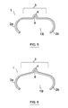
- Figure 5 shows a perspective of a third embodiment of the inventive staple.
- Figure 6 shows a perspective of a fourth embodiment of the inventive staple.
- Figure 1 shows a perspective of a first embodiment of the inventive staple. The staple (1) is a thin metal rod that is bent into an approximate omega shape (1A). In other words, the staple (1) is formed by two convex arms (2a, 2b) and a central part (3). The central part (3) is shaped towards the interior of the staple (1) and, in the embodiment of the figure, is formed with straight shapes (5a, 5b). A convex projection (4) that delimits an interior cavity (6) is formed in the central part (3) from points of inflection (10a, 10b). The staple (1) also delimits an interior cavity (7).
- Figure 2 shows the staple (1) in a closed position, once the guide element (8) has been inserted in the cavity (6) of the convex projection (4), once the plant stem or branch, not shown, has been inserted in the cavity (7) of the staple (1), and once a tool has closed the staple until the arms (2a, 2b) of the staple (1) overlap sufficiently to prevent the branch from coming loose from the staple (1). In this situation, the points of inflection (10a, 10b) come into contact, the staple (1) offering a double clamping: a clamping and tightening of the guide element (8) above said points of inflection (10a, 10b) and a clamping of the plant branch, not shown, in the interior cavity (7) which remains below the points of inflection (10a, 10b). This embodiment of the staple (1) is valid for guide elements (8) that are not overly thick, such as tapes, thin strings, etc.
- Figure 3 shows a perspective of a second embodiment of the invention, where this second staple (1) is once again a metal rod bent into a C-shape with arms (2a, 2b) and a sunken central part (3) that provides the staple (1) with an omega shape (1A). In this case, the central part (3) is formed with curved shapes (5a', 5b'), and in its central area it presents a convex projection (4') that is positioned from points of inflection (10a, 10b) and which delimits an interior cavity (6') that is larger than the interior cavity (6) of the embodiment of Figure 1.
- As can be seen in Figure 4, when the arms (2a, 2b) of the staple (1) are caused to close on themselves by the use of an appropriate tool, the points of inflection (10a, 10b) are brought together and/or come into contact to delimit two clamping areas: a clamping and tightening of the guide element (8) above the points of inflection (10a, 10b) and a clamping of the plant branch, not shown, in the interior cavity (7) which remains below the points of inflection (10a, 10b). In this case, the coming together and contact of the points of inflection (10a, 10b) does not result in the disappearance of the interior cavity (6'). In consequence, this second embodiment of the staple (1) is capable of exerting a clamping and tightening on thicker guide elements (8) than those of the embodiment of Figure 1. In other words, the staple (1) is capable of training the plant, not shown, onto thicker strings and even poles (9) and other similar elements.
- Figure 5 shows a perspective of a third embodiment of the inventive staple (1), in which the central part (3) is shaped substantially level with the arms (2a, 2b), as a result of which the staple (1) presents an approximate C-shape (1B).
- Figure 6 shows a perspective of a fourth embodiment of the inventive staple (1), in which the central part (3) is shaped above the arms (2a, 2b) and towards the exterior of the staple (1), as a result of which the staple (1) also presents an approximate C-shape (1B).
Claims (8)
- Staple (1) for tying a plant stem or branch to a guide element (8), capable of being closed providing an independent clamping of the guide element (8) and the branch, characterised in that:- the staple (1) is formed of a thin metal rod that is bent to present a shape that comprises two convex arms (2a, 2b), a central part (3), and a convex projection (4, 4') that projects towards the exterior of the staple and that is formed in said central part (3) from two points of inflection (10a, 10b),- the staple (1) delimiting two interior cavities: an interior cavity (6, 6') in the area of the convex projection (4, 4'), for clamping around the guide element (8), and an interior cavity (7) of the staple (1), for clamping around the plant stem or branch, wherein- when the staple (1) is closed, the points of inflection (10a, 10b) are brought together, the clamping areas of the guide element (8) and branch above and below said points of inflection (10a, 10b) respectively being delimited.
- Staple (1) for tying a plant stem or branch to a guide element (8), according to claim 1, wherein when the staple (1) is closed, the points of inflection (10a, 10b) are brought together and the interior cavity (6) of the convex projection (4) disappears.
- Staple (1) for tying a plant stem or branch to a guide element (8), according to claim 1, wherein when the staple (1) is closed, the points of inflection (10a, 10b) are brought together and the interior cavity (6') of the convex projection (4') does not disappear.
- Staple (1) for tying a plant stem or branch to a guide element (8), according to claims 1, 2 or 3, wherein the central part (3) is shaped towards the interior of the staple (1) giving the staple (1) an approximate omega shape (1A).
- Staple (1) for tying a plant stem or branch to a guide element (8), according to claims 1, 2 or 3, wherein the central part (3) is formed level with the arms (2a, 2b), giving the staple (1) an approximate C-shape (1B).
- Staple (1) for tying a plant stem or branch to a guide element (8), according to claims 1, 2 or 3, wherein the central part (3) is shaped towards exterior of the staple (1), giving the staple (1) an approximate C-shape (1B).
- Staple (1) for tying a plant stem or branch to a guide element (8), according to claims 1, 2, 3, 4, 5 or 6, wherein the central part (3), between the arms (2a, 2b) and the points of inflection (10a, 10b), is formed with straight shapes (5a, 5b).
- Staple (1) for tying a plant stem or branch to a guide element (8), according to claims 1, 2, 3, 4, 5 or 6, wherein the central part (3), between the arms (2a, 2b) and the points of inflection (10a, 10b), is formed with curved shapes (5a', 5b').
Applications Claiming Priority (1)
| Application Number | Priority Date | Filing Date | Title |
|---|---|---|---|
| PCT/ES2005/000020 WO2006077269A1 (en) | 2005-01-18 | 2005-01-18 | Clip for fastening plant stems or branches to a cord, post or other guide element |
Publications (2)
| Publication Number | Publication Date |
|---|---|
| EP1839482A1 true EP1839482A1 (en) | 2007-10-03 |
| EP1839482B1 EP1839482B1 (en) | 2013-03-20 |
Family
ID=36691995
Family Applications (1)
| Application Number | Title | Priority Date | Filing Date |
|---|---|---|---|
| EP05701675A Expired - Lifetime EP1839482B1 (en) | 2005-01-18 | 2005-01-18 | Clip for fastening plant stems or branches to a cord, post or other guide element |
Country Status (3)
| Country | Link |
|---|---|
| EP (1) | EP1839482B1 (en) |
| ES (1) | ES2411029T3 (en) |
| WO (1) | WO2006077269A1 (en) |
Cited By (8)
| Publication number | Priority date | Publication date | Assignee | Title |
|---|---|---|---|---|
| US20140249078A1 (en) * | 2011-10-21 | 2014-09-04 | Nestec S.A. | Whey protein micelles against muscle atrophy and sarcopenia |
| WO2015140518A1 (en) * | 2014-03-18 | 2015-09-24 | Oakthrift Corporation Ltd | Plant ties |
| BE1026927A1 (en) | 2018-12-27 | 2020-07-23 | Nico Perneel | CLAMP |
| WO2023286708A1 (en) | 2021-07-15 | 2023-01-19 | マックス株式会社 | Tying machine and method for tying |
| KR20230093436A (en) | 2020-10-30 | 2023-06-27 | 마크스 가부시기가이샤 | staple |
| EP4399960A1 (en) | 2023-01-13 | 2024-07-17 | Max Co., Ltd. | Binding machine |
| EP4399961A1 (en) | 2023-01-13 | 2024-07-17 | Max Co., Ltd. | Binding machine |
| EP4399962A1 (en) | 2023-01-13 | 2024-07-17 | Max Co., Ltd. | Binding machine |
Families Citing this family (1)
| Publication number | Priority date | Publication date | Assignee | Title |
|---|---|---|---|---|
| US12329080B2 (en) | 2022-12-21 | 2025-06-17 | Crushproof Tubing Co. | Plant support clip |
Family Cites Families (6)
| Publication number | Priority date | Publication date | Assignee | Title |
|---|---|---|---|---|
| GB357570A (en) * | 1930-06-24 | 1931-09-24 | Charles Edward West | A clip for supporting flowers, plants and the like |
| DE1582855B1 (en) | 1966-03-31 | 1970-04-23 | Gerhard Simmon | Plant fastening clip |
| AU1353683A (en) * | 1982-04-21 | 1983-10-27 | W.A. Deutsher Pty Ltd | The fastener |
| NL184038C (en) | 1984-12-17 | 1991-09-16 | Josephus Petrus Maria Buskermo | BRACKET MADE OF RESILIENT MATERIAL FOR SUPPORTING A PLANT. |
| ES285513Y (en) | 1985-03-21 | 1986-05-01 | Pons Bosch Jorge | PLANT CLAMP |
| NL9400113A (en) * | 1994-01-25 | 1995-09-01 | Emperor Plastics B V | Support member for plants |
-
2005
- 2005-01-18 WO PCT/ES2005/000020 patent/WO2006077269A1/en not_active Ceased
- 2005-01-18 ES ES05701675T patent/ES2411029T3/en not_active Expired - Lifetime
- 2005-01-18 EP EP05701675A patent/EP1839482B1/en not_active Expired - Lifetime
Non-Patent Citations (1)
| Title |
|---|
| See references of WO2006077269A1 * |
Cited By (12)
| Publication number | Priority date | Publication date | Assignee | Title |
|---|---|---|---|---|
| US20140249078A1 (en) * | 2011-10-21 | 2014-09-04 | Nestec S.A. | Whey protein micelles against muscle atrophy and sarcopenia |
| WO2015140518A1 (en) * | 2014-03-18 | 2015-09-24 | Oakthrift Corporation Ltd | Plant ties |
| GB2538653A (en) * | 2014-03-18 | 2016-11-23 | John Thorn James | Plant ties |
| BE1026927A1 (en) | 2018-12-27 | 2020-07-23 | Nico Perneel | CLAMP |
| BE1026927B1 (en) * | 2018-12-27 | 2020-07-28 | Nico Perneel | CLAMP |
| KR20230093436A (en) | 2020-10-30 | 2023-06-27 | 마크스 가부시기가이샤 | staple |
| WO2023286708A1 (en) | 2021-07-15 | 2023-01-19 | マックス株式会社 | Tying machine and method for tying |
| KR20240034701A (en) | 2021-07-15 | 2024-03-14 | 마크스 가부시기가이샤 | Binding machine and binding method |
| EP4399960A1 (en) | 2023-01-13 | 2024-07-17 | Max Co., Ltd. | Binding machine |
| EP4399961A1 (en) | 2023-01-13 | 2024-07-17 | Max Co., Ltd. | Binding machine |
| EP4399962A1 (en) | 2023-01-13 | 2024-07-17 | Max Co., Ltd. | Binding machine |
| US12358670B2 (en) | 2023-01-13 | 2025-07-15 | Max Co., Ltd. | Binding machine |
Also Published As
| Publication number | Publication date |
|---|---|
| WO2006077269A1 (en) | 2006-07-27 |
| EP1839482B1 (en) | 2013-03-20 |
| ES2411029T3 (en) | 2013-07-04 |
Similar Documents
| Publication | Publication Date | Title |
|---|---|---|
| EP1839482B1 (en) | Clip for fastening plant stems or branches to a cord, post or other guide element | |
| US8978210B2 (en) | Adjustable-length tie-wrap | |
| US8186364B2 (en) | Handle free claw clip | |
| US20050217198A1 (en) | Swiveling rebar fastener | |
| US5758390A (en) | Reversible cable tie | |
| US8590544B2 (en) | Hair clip apparatus and method | |
| US8978211B2 (en) | Universal adjustable-length tie-wrap | |
| US8281462B2 (en) | Bundle tie | |
| US20240410497A1 (en) | Cord cuff for securing an end of a cord | |
| US7380371B2 (en) | Clip | |
| KR20240004793A (en) | System and method for double hook flat strap attachment device | |
| US20220049796A1 (en) | Cord cuff for securing an end of a cord | |
| US5081746A (en) | Flexible closure device | |
| US4114859A (en) | Fence staple | |
| KR20070039428A (en) | Fruit bag | |
| US11555530B1 (en) | Cinching connector apparatus, system and method for attaching a line to a functional sheet product | |
| CA2455888A1 (en) | Hose clamp arrangement | |
| US20030121526A1 (en) | Hair clip | |
| US20100186765A1 (en) | Hair Styling Tool, System and Method of Use | |
| KR20070072473A (en) | Fruit bag | |
| US20120180269A1 (en) | Adjustable-Length Tie-Wrap | |
| JP2013236570A (en) | Grafting clip | |
| JPH04356142A (en) | Binding tool for branch and leaf of tree or the like | |
| DE2521165A1 (en) | Vine branch clip fixing device - has jaw handles spring loaded apart and jaws initially bending clip at base | |
| US20100294817A1 (en) | Pvc primer and glue can caddy |
Legal Events
| Date | Code | Title | Description |
|---|---|---|---|
| PUAI | Public reference made under article 153(3) epc to a published international application that has entered the european phase |
Free format text: ORIGINAL CODE: 0009012 |
|
| 17P | Request for examination filed |
Effective date: 20070717 |
|
| AK | Designated contracting states |
Kind code of ref document: A1 Designated state(s): AT BE BG CH CY CZ DE DK EE ES FI FR GB GR HU IE IS IT LI LT LU MC NL PL PT RO SE SI SK TR |
|
| RIN1 | Information on inventor provided before grant (corrected) |
Inventor name: CORCHON ZAMORA, CARLOS |
|
| DAX | Request for extension of the european patent (deleted) | ||
| 17Q | First examination report despatched |
Effective date: 20100211 |
|
| RAP1 | Party data changed (applicant data changed or rights of an application transferred) |
Owner name: DESARROLLOS ESPECIALES DE SISTEMAS DE ANCLAJE, S.A |
|
| GRAP | Despatch of communication of intention to grant a patent |
Free format text: ORIGINAL CODE: EPIDOSNIGR1 |
|
| GRAS | Grant fee paid |
Free format text: ORIGINAL CODE: EPIDOSNIGR3 |
|
| GRAA | (expected) grant |
Free format text: ORIGINAL CODE: 0009210 |
|
| AK | Designated contracting states |
Kind code of ref document: B1 Designated state(s): AT BE BG CH CY CZ DE DK EE ES FI FR GB GR HU IE IS IT LI LT LU MC NL PL PT RO SE SI SK TR |
|
| REG | Reference to a national code |
Ref country code: GB Ref legal event code: FG4D |
|
| REG | Reference to a national code |
Ref country code: CH Ref legal event code: EP |
|
| REG | Reference to a national code |
Ref country code: IE Ref legal event code: FG4D |
|
| REG | Reference to a national code |
Ref country code: AT Ref legal event code: REF Ref document number: 601471 Country of ref document: AT Kind code of ref document: T Effective date: 20130415 |
|
| REG | Reference to a national code |
Ref country code: DE Ref legal event code: R096 Ref document number: 602005038646 Country of ref document: DE Effective date: 20130516 |
|
| REG | Reference to a national code |
Ref country code: CH Ref legal event code: NV Representative=s name: MOINAS AND SAVOYE SA, CH |
|
| REG | Reference to a national code |
Ref country code: ES Ref legal event code: FG2A Ref document number: 2411029 Country of ref document: ES Kind code of ref document: T3 Effective date: 20130704 |
|
| PG25 | Lapsed in a contracting state [announced via postgrant information from national office to epo] |
Ref country code: LT Free format text: LAPSE BECAUSE OF FAILURE TO SUBMIT A TRANSLATION OF THE DESCRIPTION OR TO PAY THE FEE WITHIN THE PRESCRIBED TIME-LIMIT Effective date: 20130320 Ref country code: SE Free format text: LAPSE BECAUSE OF FAILURE TO SUBMIT A TRANSLATION OF THE DESCRIPTION OR TO PAY THE FEE WITHIN THE PRESCRIBED TIME-LIMIT Effective date: 20130320 Ref country code: BG Free format text: LAPSE BECAUSE OF FAILURE TO SUBMIT A TRANSLATION OF THE DESCRIPTION OR TO PAY THE FEE WITHIN THE PRESCRIBED TIME-LIMIT Effective date: 20130620 |
|
| REG | Reference to a national code |
Ref country code: AT Ref legal event code: MK05 Ref document number: 601471 Country of ref document: AT Kind code of ref document: T Effective date: 20130320 |
|
| REG | Reference to a national code |
Ref country code: NL Ref legal event code: T3 |
|
| REG | Reference to a national code |
Ref country code: LT Ref legal event code: MG4D |
|
| PG25 | Lapsed in a contracting state [announced via postgrant information from national office to epo] |
Ref country code: GR Free format text: LAPSE BECAUSE OF FAILURE TO SUBMIT A TRANSLATION OF THE DESCRIPTION OR TO PAY THE FEE WITHIN THE PRESCRIBED TIME-LIMIT Effective date: 20130621 Ref country code: SI Free format text: LAPSE BECAUSE OF FAILURE TO SUBMIT A TRANSLATION OF THE DESCRIPTION OR TO PAY THE FEE WITHIN THE PRESCRIBED TIME-LIMIT Effective date: 20130320 Ref country code: FI Free format text: LAPSE BECAUSE OF FAILURE TO SUBMIT A TRANSLATION OF THE DESCRIPTION OR TO PAY THE FEE WITHIN THE PRESCRIBED TIME-LIMIT Effective date: 20130320 |
|
| PG25 | Lapsed in a contracting state [announced via postgrant information from national office to epo] |
Ref country code: SK Free format text: LAPSE BECAUSE OF FAILURE TO SUBMIT A TRANSLATION OF THE DESCRIPTION OR TO PAY THE FEE WITHIN THE PRESCRIBED TIME-LIMIT Effective date: 20130320 Ref country code: PT Free format text: LAPSE BECAUSE OF FAILURE TO SUBMIT A TRANSLATION OF THE DESCRIPTION OR TO PAY THE FEE WITHIN THE PRESCRIBED TIME-LIMIT Effective date: 20130722 Ref country code: CZ Free format text: LAPSE BECAUSE OF FAILURE TO SUBMIT A TRANSLATION OF THE DESCRIPTION OR TO PAY THE FEE WITHIN THE PRESCRIBED TIME-LIMIT Effective date: 20130320 Ref country code: IS Free format text: LAPSE BECAUSE OF FAILURE TO SUBMIT A TRANSLATION OF THE DESCRIPTION OR TO PAY THE FEE WITHIN THE PRESCRIBED TIME-LIMIT Effective date: 20130720 Ref country code: EE Free format text: LAPSE BECAUSE OF FAILURE TO SUBMIT A TRANSLATION OF THE DESCRIPTION OR TO PAY THE FEE WITHIN THE PRESCRIBED TIME-LIMIT Effective date: 20130320 Ref country code: RO Free format text: LAPSE BECAUSE OF FAILURE TO SUBMIT A TRANSLATION OF THE DESCRIPTION OR TO PAY THE FEE WITHIN THE PRESCRIBED TIME-LIMIT Effective date: 20130320 Ref country code: AT Free format text: LAPSE BECAUSE OF FAILURE TO SUBMIT A TRANSLATION OF THE DESCRIPTION OR TO PAY THE FEE WITHIN THE PRESCRIBED TIME-LIMIT Effective date: 20130320 |
|
| PG25 | Lapsed in a contracting state [announced via postgrant information from national office to epo] |
Ref country code: PL Free format text: LAPSE BECAUSE OF FAILURE TO SUBMIT A TRANSLATION OF THE DESCRIPTION OR TO PAY THE FEE WITHIN THE PRESCRIBED TIME-LIMIT Effective date: 20130320 Ref country code: CY Free format text: LAPSE BECAUSE OF FAILURE TO SUBMIT A TRANSLATION OF THE DESCRIPTION OR TO PAY THE FEE WITHIN THE PRESCRIBED TIME-LIMIT Effective date: 20130320 |
|
| PLBE | No opposition filed within time limit |
Free format text: ORIGINAL CODE: 0009261 |
|
| STAA | Information on the status of an ep patent application or granted ep patent |
Free format text: STATUS: NO OPPOSITION FILED WITHIN TIME LIMIT |
|
| PG25 | Lapsed in a contracting state [announced via postgrant information from national office to epo] |
Ref country code: DK Free format text: LAPSE BECAUSE OF FAILURE TO SUBMIT A TRANSLATION OF THE DESCRIPTION OR TO PAY THE FEE WITHIN THE PRESCRIBED TIME-LIMIT Effective date: 20130320 |
|
| 26N | No opposition filed |
Effective date: 20140102 |
|
| REG | Reference to a national code |
Ref country code: DE Ref legal event code: R097 Ref document number: 602005038646 Country of ref document: DE Effective date: 20140102 |
|
| PG25 | Lapsed in a contracting state [announced via postgrant information from national office to epo] |
Ref country code: LU Free format text: LAPSE BECAUSE OF FAILURE TO SUBMIT A TRANSLATION OF THE DESCRIPTION OR TO PAY THE FEE WITHIN THE PRESCRIBED TIME-LIMIT Effective date: 20140118 Ref country code: MC Free format text: LAPSE BECAUSE OF FAILURE TO SUBMIT A TRANSLATION OF THE DESCRIPTION OR TO PAY THE FEE WITHIN THE PRESCRIBED TIME-LIMIT Effective date: 20130320 |
|
| REG | Reference to a national code |
Ref country code: IE Ref legal event code: MM4A |
|
| PG25 | Lapsed in a contracting state [announced via postgrant information from national office to epo] |
Ref country code: IE Free format text: LAPSE BECAUSE OF NON-PAYMENT OF DUE FEES Effective date: 20140118 |
|
| REG | Reference to a national code |
Ref country code: FR Ref legal event code: PLFP Year of fee payment: 12 |
|
| PG25 | Lapsed in a contracting state [announced via postgrant information from national office to epo] |
Ref country code: TR Free format text: LAPSE BECAUSE OF FAILURE TO SUBMIT A TRANSLATION OF THE DESCRIPTION OR TO PAY THE FEE WITHIN THE PRESCRIBED TIME-LIMIT Effective date: 20130320 Ref country code: HU Free format text: LAPSE BECAUSE OF FAILURE TO SUBMIT A TRANSLATION OF THE DESCRIPTION OR TO PAY THE FEE WITHIN THE PRESCRIBED TIME-LIMIT; INVALID AB INITIO Effective date: 20050118 |
|
| REG | Reference to a national code |
Ref country code: CH Ref legal event code: PFA Owner name: DESARROLLOS ESPECIALES DE SISTEMAS DE ANCLAJE,, ES Free format text: FORMER OWNER: DESARROLLOS ESPECIALES DE SISTEMAS DE ANCLAJE, S.A., ES |
|
| REG | Reference to a national code |
Ref country code: FR Ref legal event code: PLFP Year of fee payment: 13 |
|
| REG | Reference to a national code |
Ref country code: FR Ref legal event code: PLFP Year of fee payment: 14 |
|
| REG | Reference to a national code |
Ref country code: DE Ref legal event code: R081 Ref document number: 602005038646 Country of ref document: DE Owner name: DESARROLLOS ESPECIALES DE SISTEMAS DE ANCLAJE,, ES Free format text: FORMER OWNER: DESARROLLOS ESPECIALES DE SISTEMAS DE ANCLAJE, S.A., 08840 VILADECANS, ES |
|
| PGFP | Annual fee paid to national office [announced via postgrant information from national office to epo] |
Ref country code: NL Payment date: 20240126 Year of fee payment: 20 |
|
| PGFP | Annual fee paid to national office [announced via postgrant information from national office to epo] |
Ref country code: ES Payment date: 20240201 Year of fee payment: 20 |
|
| PGFP | Annual fee paid to national office [announced via postgrant information from national office to epo] |
Ref country code: DE Payment date: 20240129 Year of fee payment: 20 Ref country code: GB Payment date: 20240129 Year of fee payment: 20 Ref country code: CH Payment date: 20240202 Year of fee payment: 20 |
|
| PGFP | Annual fee paid to national office [announced via postgrant information from national office to epo] |
Ref country code: IT Payment date: 20240122 Year of fee payment: 20 Ref country code: FR Payment date: 20240125 Year of fee payment: 20 Ref country code: BE Payment date: 20240129 Year of fee payment: 20 |
|
| REG | Reference to a national code |
Ref country code: DE Ref legal event code: R071 Ref document number: 602005038646 Country of ref document: DE |
|
| REG | Reference to a national code |
Ref country code: NL Ref legal event code: MK Effective date: 20250117 Ref country code: ES Ref legal event code: FD2A Effective date: 20250124 |
|
| REG | Reference to a national code |
Ref country code: CH Ref legal event code: PL |
|
| REG | Reference to a national code |
Ref country code: GB Ref legal event code: PE20 Expiry date: 20250117 |
|
| REG | Reference to a national code |
Ref country code: BE Ref legal event code: MK Effective date: 20250118 |
|
| PG25 | Lapsed in a contracting state [announced via postgrant information from national office to epo] |
Ref country code: ES Free format text: LAPSE BECAUSE OF EXPIRATION OF PROTECTION Effective date: 20250119 |
|
| PG25 | Lapsed in a contracting state [announced via postgrant information from national office to epo] |
Ref country code: GB Free format text: LAPSE BECAUSE OF EXPIRATION OF PROTECTION Effective date: 20250117 |