EP1838566B1 - Steering control apparatus and method - Google Patents
Steering control apparatus and method Download PDFInfo
- Publication number
- EP1838566B1 EP1838566B1 EP05812061.9A EP05812061A EP1838566B1 EP 1838566 B1 EP1838566 B1 EP 1838566B1 EP 05812061 A EP05812061 A EP 05812061A EP 1838566 B1 EP1838566 B1 EP 1838566B1
- Authority
- EP
- European Patent Office
- Prior art keywords
- steering
- vehicle
- reaction force
- steering wheel
- road surface
- Prior art date
- Legal status (The legal status is an assumption and is not a legal conclusion. Google has not performed a legal analysis and makes no representation as to the accuracy of the status listed.)
- Active
Links
- 238000000034 method Methods 0.000 title claims description 15
- 238000006243 chemical reaction Methods 0.000 claims description 76
- 238000006557 surface reaction Methods 0.000 claims description 63
- 238000012937 correction Methods 0.000 claims description 21
- 230000007423 decrease Effects 0.000 claims description 10
- 230000004044 response Effects 0.000 claims description 9
- 238000010586 diagram Methods 0.000 description 10
- 238000001514 detection method Methods 0.000 description 7
- 230000000694 effects Effects 0.000 description 6
- 230000035939 shock Effects 0.000 description 6
- 230000008859 change Effects 0.000 description 5
- 230000001133 acceleration Effects 0.000 description 4
- 230000004907 flux Effects 0.000 description 3
- 238000004886 process control Methods 0.000 description 3
- 230000005484 gravity Effects 0.000 description 2
- 238000012986 modification Methods 0.000 description 2
- 230000004048 modification Effects 0.000 description 2
- 238000012545 processing Methods 0.000 description 2
- 230000002730 additional effect Effects 0.000 description 1
- 230000005540 biological transmission Effects 0.000 description 1
- 230000001419 dependent effect Effects 0.000 description 1
- 238000013461 design Methods 0.000 description 1
- 238000006073 displacement reaction Methods 0.000 description 1
- 238000011156 evaluation Methods 0.000 description 1
- 230000007246 mechanism Effects 0.000 description 1
- 230000009467 reduction Effects 0.000 description 1
- 230000001052 transient effect Effects 0.000 description 1
Images


Classifications
-
- B—PERFORMING OPERATIONS; TRANSPORTING
- B62—LAND VEHICLES FOR TRAVELLING OTHERWISE THAN ON RAILS
- B62D—MOTOR VEHICLES; TRAILERS
- B62D6/00—Arrangements for automatically controlling steering depending on driving conditions sensed and responded to, e.g. control circuits
- B62D6/008—Control of feed-back to the steering input member, e.g. simulating road feel in steer-by-wire applications
-
- B—PERFORMING OPERATIONS; TRANSPORTING
- B62—LAND VEHICLES FOR TRAVELLING OTHERWISE THAN ON RAILS
- B62D—MOTOR VEHICLES; TRAILERS
- B62D5/00—Power-assisted or power-driven steering
- B62D5/001—Mechanical components or aspects of steer-by-wire systems, not otherwise provided for in this maingroup
- B62D5/005—Mechanical components or aspects of steer-by-wire systems, not otherwise provided for in this maingroup means for generating torque on steering wheel or input member, e.g. feedback
- B62D5/006—Mechanical components or aspects of steer-by-wire systems, not otherwise provided for in this maingroup means for generating torque on steering wheel or input member, e.g. feedback power actuated
-
- B—PERFORMING OPERATIONS; TRANSPORTING
- B62—LAND VEHICLES FOR TRAVELLING OTHERWISE THAN ON RAILS
- B62D—MOTOR VEHICLES; TRAILERS
- B62D5/00—Power-assisted or power-driven steering
- B62D5/04—Power-assisted or power-driven steering electrical, e.g. using an electric servo-motor connected to, or forming part of, the steering gear
- B62D5/0457—Power-assisted or power-driven steering electrical, e.g. using an electric servo-motor connected to, or forming part of, the steering gear characterised by control features of the drive means as such
- B62D5/046—Controlling the motor
- B62D5/0466—Controlling the motor for returning the steering wheel to neutral position
Definitions
- the present invention relates to the field of steering control for vehicles and in particular to electronic steering control systems.
- the steering reaction force correction proportional to the detected road surface reaction force is computed and added to the steering reaction force, so that the condition of the road surface is transmitted to the driver.
- a steering force (T) applied to the steering column (steering shaft) is computed.
- a control value (aT) (where a is the coefficient corresponding to the steering force gear ratio) for rotating the steering shaft in the direction of applied steering force (T) is also computed.
- the road surface reaction force from the steering reaction force sensor is transmitted to the steering reaction force, for example, when the vehicle turns an L-shaped corner, so that quick return steering is required. If the tire dips due to the rough road surface (holes, etc.), due to the signal from the steering reaction force sensor, quick maneuvering of the steering wheel may be hindered, which is undesirable (see Figure 7 ). If the embodiment of the present invention is not applied, this occurs because the steering reaction force is added to track the kickback from the road surface, the steering force rises abruptly, and it becomes difficult for the driver to respond quickly.
- Document WO 2004/101346 A1 discloses a steering control device wherein a steering shaft reaction torque is estimated by steering shaft reaction torque-estimating means and reference road surface reaction torque is estimated by reference road surface reaction torque-estimating means. The obtained steering shaft reaction torque and reference road surface reaction torque are weighted. Based on the weighted result, aimed steering reaction torque is set by aimed steering reaction torque-producing means. The width and inclination of a hysteresis of the aimed steering reaction torque are each adjusted so that steering feeling is improved.
- the object underlying the present invention is achieved by a steering control device according to independent claim 1, by a vehicle according to independent claim 2, and by a method for controlling steering in a vehicle according to independent claim 11.
- Preferred embodiments are defined in the respective dependent claims.
- a steering control device for use in a vehicle having a steering wheel that receives steering input, and an electronically-controlled steering unit that turns the vehicle's wheels over a road surface based on the position of the steering wheel.
- the steering control device includes a reaction force device coupled to the steering wheel and responsive to a control signal to apply a steering reaction force to the steering wheel; and a controller adapted to generate the control signal in response to the movement of the steering wheel and the road surface reaction force.
- the controller varies the control signal to increase the steering reaction force in response to the road surface reaction force when the steering wheel is turning and to decrease the reaction force in response to the road surface force when the steering wheel is returning.
- a method for controlling steering in a vehicle having a steering wheel and a reaction device to impose a steering reaction force onto the steering wheel in response to a steering force control signal includes calculating the steering force control signal based on a road surface reaction. force and a gain; determining whether the steering wheel is in a turning or returning mode; and setting the gain at a higher value when the steering wheel is in a turning mode.
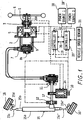
- FIG 1 is an overall system diagram illustrating the vehicle steering device of the first embodiment.
- Figures 2 a-c are detailed diagrams illustrating the clutch, cable column, and torque sensor components, respectively, in the vehicle steering device of the first embodiment.
- the vehicle steering device is composed of a reaction force device, an auxiliary device, an electronically-controlled steering device, and a controller.
- the reaction force device has steering angle sensor 1, encoder 2, torque sensors 3, and reaction force motor 5.
- the steering angle sensor 1 is a means for detecting the angular position of steering wheel 6. It is set on a column shaft 8a that connects a cable column 7 and a steering wheel 6. That is, steering angle sensor 1 is placed between steering wheel 6 and torque sensors 3 and is unaffected by the change in angle due to the twisting of torque sensors 3 so that the sensor 1 can detect the steering angle.
- an absolute type resolver (not shown) or the like is used.
- the torque sensors 3 form a double system and are arranged between the steering angle sensor 1 and reaction force motor 5.
- the system is made up of two torque sensors, that is, torque sensor 3 and torque sensor 12.
- Figure 2C is a diagram illustrating in detail a torque sensor unit.
- Each torque sensor 3 has a torsion bar extending in the axial direction, a first shaft connected to one end of the torsion bar and coaxial to the torsion bar, a second shaft connected to the other end of the torsion bar and is coaxial to the torsion bar and the first shaft, a first magnetic body fixed to the first shaft, a second magnetic body fixed to the second shaft, a coil facing the first magnetic body and the second magnetic body, and a third magnetic body that forms a magnetic circuit together with the first magnetic body and second magnetic body.
- the coil detects the torque from the output signal on the basis of the inductance that changes corresponding to the relative displacement between the first magnetic body and the second magnetic body on the basis of the twisting of the torsion bar.
- the reaction force motor 5 is a reaction force actuator that imparts a reaction force to the steering wheel 6.
- the reaction force motor 5 is made of a 1-rotor/1-stator type of electric motor with the column shaft 8a as the rotary shaft.
- the housing is fixed at an appropriate location on the vehicle body.
- a brushless motor is used as the reaction force motor 5 with the encoder 2 and a Hall IC (not shown in the figure), which are required for use with a brushless motor. If only a Hall IC is used, although it will be possible to drive the motor that generates the motor torque, nevertheless there will be small variations in the output torque, and the feel of the steering reaction force will be poor.
- encoder 2 is placed on the shaft of column shaft 8a to control the motor. As a result, the small torque variations can be reduced, and the steering reaction force feel is improved.
- a resolver can be used in place of encoder 2.
- the auxiliary unit is composed of cable column 7 and clutch 9.
- the clutch 9 is arranged between column shaft 8a and pulley shaft 8b.
- An electromagnetic clutch is used in the first embodiment.
- Figure 2A is a diagram illustrating in detail the clutch component 9.
- clutch 9 When power is turned on to the electromagnetic clutch, clutch 9 generates magnetic flux ⁇ .
- the armature is magnetically drawn to the brushes of the rotor against the restoring force of a leaf spring
- column shaft 8a, the input shaft, and pulley shaft 8b, the output shaft, are connected to each other.
- steering wheel 6 is rotated, its rotational force is transmitted via clutch 9 to the pulley of cable column 7 to rotate the pulley of cable column 7.
- the rotational force is transmitted via clutch 9 to steering wheel 6.
- the transmission torque capacity of clutch 9 can be set as desired by changing the drawing force as magnetic flux ⁇ generated by the magnetic coil is changed. Also, a scheme in which the clutch is released when the power is turned on may also be used.
- the cable column 7 has a mechanical backup mechanism that can play the part of the column shaft in transmitting the torque while it detours to avoid interference with the element included between the reaction force device and the steering device.
- Figure 2B is a diagram illustrating in detail the cable column unit. In the structure of cable column 7, two interior cables, each end of which is fixed to a reel 22, are wound onto the two reels 22, and the two ends of the exterior sheath in which two inner cables are inserted are fixed to two reel housings.
- the steering unit includes encoder 10, steering angle sensor 11, torque sensors 12, steering motors 14, steering unit (steered wheel turning unit) 15, and steered wheels 16, 16'.
- the steering angle sensor 11 and torque sensors 12 are mounted on pinion shaft 17, on one end of which the pulley of cable column 7 is attached, and on the other end of which a pinion gear is formed.
- a steering angle sensor 11 an absolute type resolver or the like, which detects the rotational velocity of the shaft can be used.
- torque sensors 3, and torque sensors 12 form a double system that detects torque from changes in inductance.
- Steering angle sensor 11 is set on the side of cable column 7, and torque sensors 12 are set on the side of steering unit 15. As a result, when the steering angle is detected by steering angle sensor 11, it is unaffected by the change in the angle due to the twisting of torque sensors 12.
- the steering motors 14 have a structure in which a pinion gear engaged to the worm gear set at the central position between steering angle sensor 11 of the pinion shaft 17 and torque sensors 12 is set on the motor shaft, so that a steering torque is applied to pinion shaft 17 when the motor is on.
- the steering motors 14 form a double system with a 1-rotor/2-stator structure.
- the steering motors 14 are brushless motors that form first and second steering motors 14.
- encoder 10 and a Hall IC (not shown in the figure) are used.
- the steering unit 15 has a structure in which left/right steered road wheels 16, 16' turn as pinion shaft 17 rotates. It has rack shaft 15b that forms a rack gear engaged with the pinion gear of pinion shaft 17 and inserted in rack tube 15a, tie rods 15c, 15c' fixed to the two ends of rack shaft 15b extending in the left/right direction of the vehicle, and knuckle arms 15d, 15d' having one end fixed to the tie rods 15c, 15c' and the other end fixed to the steered road wheels 16, 16'.
- the controller has a double system design composed of two power sources 18, 18' and two controllers 19, 19' that perform processing and arithmetic operations.
- the controllers 19, 19' receive the detected signals from the following parts: steering angle sensor 1, encoder 2, torque sensors 3, and the Hall IC of the reaction force device, as well as encoder 10, steering angle sensor 11, torque sensors 12, Hall IC, and vehicle speed sensor 21 (vehicle speed detection means) of the steering device.
- controller 19 sets the control quantities of reaction force motor 5 and steering motor 14, and controls and drives each of steering motors 14. Also, during ordinary system conditions, controller 19 releases the clutch 9. Otherwise, the system engages clutch 9 to establish a mechanical connection between steering wheel 6 and the steered road wheels 16, 16'.
- Th Kp ⁇ ⁇ + Gf ⁇ F
- (Kp) represents the steering angle feedback gain
- ⁇ represents the steering angle
- (Gf) represents the road surface reaction force feedback gain
- (F) represents the road surface reaction force.
- the first term on the right-hand side sets the control value of the steering reaction force on the basis of steering angle ⁇
- the second term on the right-hand side sets the control value on the basis of road surface reaction force (F), so that it can reflect the influence on the steering reaction force of the force on the tires from the road surface on the tires.
- road surface reaction force feedback gain changes as a function of the steering state. Its value is set such that in the case of turning the steering wheel, the road surface feel is transmitted to the driver through an appropriate steering reaction force.
- the amount of feedback of the road surface reaction force component is set smaller so that during the steering wheel return operation, the steering wheel is not hindered by excessive shock forces, etc.
- the (Low), (High) are determined on the basis of the graph to be explained below ( Figure 4 ). However, they may also be preset constants.
- Kd and Kdd are preset constants.
- Figure 3 is a flow chart illustrating the method for setting road surface reaction force feedback gain (Gf). Each step will be explained below.
- step S1 the signal from steering angle sensor 1 is read, and process control then goes to step S2.
- step S2 from the sensor signal read in step S1, the steering angle and steering angle velocity are computed (corresponding to the steering angle velocity detection means), and it is determined whether the steering wheel is in the return state (corresponding to the turn/return judgment means). If YES, control goes to step S3, and if NO, it goes to step S4.
- step S3 the road surface reaction force feedback gain (Gf) is set Low (corresponding to the steering reaction force correction means), and it returns.
- step S4 road surface reaction force feedback gain (Gf) is set to High, and it returns.
- Figure 4 is a graph used to set road surface reaction force feedback gain (Gf) corresponding to road surface reaction force F.
- Gf road surface reaction force feedback gain
- (L1) is set on the basis of the graph shown in Figure 5 .
- (L1) has a maximum value of 1 in the range of high frequency of occurrence generated for steering angle velocity d ⁇ /dt in the case of high vehicle speed, and the value decreases as the steering angle velocity d ⁇ /dt rises.
- the value L1 reaches the maintain value, L1min.
- the road surface reaction force amount of feedback in the steering wheel return operation is set smaller in the low velocity region. That is, the higher the speed, the more sensitive the vehicle behavior with respect to steering wheel maneuvering, so that even in the steering wheel return operation, road surface reaction force feedback is still required.
- the amount of feedback for the road surface reaction force is set to be smaller in the case of steering wheel return when the vehicle speed (V) is lower.
- (L2) is set on the basis of the graph shown in Figure 6 .
- (L2) rises in proportion to vehicle speed V. It is set such that it reaches the maximum value 1 when vehicle speed (V) reaches the high frequency of occurrence region when the vehicle is in a high-traffic area.
- the average value of the detection results (F1), (F2) of the steering reaction force sensors set at the two ends of the steering rack is taken as steering reaction force (F) is applied to the steering shaft (pinion shaft).
- rotation control value (Mm) of the steering shaft is computed using the following Equation 3, and the reaction force control signal corresponding to rotation control value Mm is output to steering shaft motor.
- Mm Gm ⁇ aT ⁇ F
- (Gm) represents the gain coefficient indicating the gain of the output signal.
- steering reaction force correction (Gf x F) is added to steering wheel 6.
- the vehicle steering device includes the following parts: turn/return judgment means that judges turn/return of steering wheel 6, and a steering reaction force correction means that has a smaller road surface reaction force feedback gain (Gf) during return of steering wheel 1 than during its initial turning. It is possible to suppress the change in the steering force accompanying the shock from the road, and it is possible to reduce the probability of an ineffective steering wheel.
- the steering reaction force correction means has a smaller road surface reaction force feedback gain (Gf) for a higher steering angle velocity d ⁇ /dt of steering wheel 1, it is possible to ensure that an even quicker return of the steering wheel 6 by the driver is not hindered.
- the steering reaction force correction means has a smaller road surface reaction force feedback gain (Gf) for a lower vehicle speed V, it is possible both to feed back the road surface reaction force in the high-speed region and to improve the steering wheel return operation in the low-speed region.
- Gf road surface reaction force feedback gain
- the road surface reaction force amount of feedback is changed corresponding to the vehicle state value.
- the structure of the second embodiment is the same as that of the first embodiment shown in Figures 1 and 2 , so that its explanation will not be repeated.
- the control value is set corresponding to the vehicle state value. If the amount of feedback of the road surface reaction force in the steering wheel return operation is set to a small value, the overall steering reaction force may become too small. In this case, as the vehicle state value, the yaw rate is computed (corresponding to the vehicle state value detection means). It also computes gain constant (Gy) corresponding to the amount of feedback of the road surface reaction force or lower and reduction component (YD) of the amount of feedback of the road surface reaction force. By adding it to the control value of reaction force motor (4), it is possible to prevent the steering reaction force from becoming too small.
- control value (Th) of reaction force motor (4) can be described by Equation 4 below.
- Th Kp ⁇ ⁇ + Kd ⁇ d ⁇ / dt + Kdd ⁇ d 2 0 / dt 2 + Ky ⁇ ⁇ + Gf ⁇ F
- the method for computing the yaw rate is discussed hereinafter.
- the yaw rate ⁇ can be obtained using the Equation 5 below from steering angle ⁇ and vehicle speed (V) by means of a mathematical operation on the vehicle movement.
- ⁇ G ⁇ ⁇ n 2 ⁇ Tr s + 1 / Tr ⁇ ⁇ / s 2 + 2 ⁇ ns + ⁇ 2
- Lf represents the distance between the center of gravity and the front shaft
- Lr represents the distance between the center of gravity and the rear shaft
- Kf represents the cornering force of the front wheels
- Kr represents the cornering force of the rear wheels
- m represents the weight of the vehicle
- s represents the Laplace operator.
- Equation 5 the value obtained using the Equation 5 is used as the estimated value of yaw rate ⁇ .
- the present invention is not limited to this scheme.
- Figure 11 is a diagram illustrating the return steering operation of the second embodiment (solid lines) as compared to the first embodiment (dotted lines).
- (YD) corresponding to the amount of feedback of the road surface reaction force is added to the steering force in the second embodiment. Consequently, when the road surface reaction force changes without influence of the lateral acceleration and yaw, it is possible to reduce the change in the steering force accompanying the shock, while preventing the steering force from becoming too small.
- the second embodiment also provides the following effect, in that the second embodiment of the invention has a steering reaction force correction value estimation means that estimates (YD) corresponding to the decrease in the amount of feedback of the road surface reaction force from yaw rate ⁇ .
- the steering reaction force correction means adds the steering reaction force component (Gy x YD) corresponding to yaw rate ⁇ . Consequently, it can reduce the change in the steering force, and it can prevent the steering force from becoming too small.
- the third embodiment is an example of correcting the amount of feedback of the road surface reaction force when the vehicle is within the rotation limit region.
- the rotation limit region refers to the state in which lateral tire skidding takes place. Also, since the structure of the third embodiment is the same as that of the first embodiment shown in Figure 1 , it will not be explained in detail again.
- Figure 12 is a flow chart illustrating the method for setting road surface reaction force feedback gain (Gf) of the third embodiment. In the following, an explanation will be given regarding the various processing steps.
- step S11 the signals from steering angle sensor 11 and vehicle speed sensor 21 are read, and process control goes to step S12.
- step S12 from the steering angle of steered wheels 16, 16, vehicle speed V, and yaw rate ⁇ of the vehicle read from step S11, it is determined whether the vehicle is within the rotation limit region with reference to the graph shown in Figure 13 (corresponding to the rotation limit judgment means). If YES, it goes to step S13, and, if NO, it goes to step S14. In step S13, road surface reaction force feedback gain (Gf) is fixed at (High), and then process control returns. In step S14, control is continued by varying road surface reaction force feedback gain (Gf) in the steering wheel turn/return operation, and then it returns.
- Gf road surface reaction force feedback gain
- the correction control of the amount of feedback of the road surface reaction force is released. Consequently, the steering reaction force corresponding to the vehicle behavior can be transmitted to the operator. Consequently, accompanying the decrease in the amount of feedback of the road surface reaction force, the steering correction by the operator is not hindered.
- vehicle steering device has the following additional effect in that there is a rotation limit region judgment means that determines whether the vehicle is at the rotation limit on the basis of the steering angle of steered wheels 16, 16' and the yaw rate ⁇ of the vehicle.
- the steering reaction force correction means does not reduce the amount of the steering reaction force correction, so that by reducing the amount of feedback of the road surface reaction force, the steering correction operation by the driver is not hindered.
- the yaw rate is computed using Equation 5.
- the detection value from a yaw rate sensor.
- a controller can include control function distributed among multiple processors.
Description
- The present invention relates to the field of steering control for vehicles and in particular to electronic steering control systems.
- In a conventional steer-by-wire system as described in Japanese Kokai Patent Application No.
Hei 10[1998]-217988 - However, in the vehicle steering device of the prior art, for example, when the vehicle turns an L-shaped corner so that a quick steering wheel response is required, or a shock from the road surface is transmitted due to a bumpy road surface as the steering wheel is turned back, a transient steering force occurs abruptly, the steering wheel may hinder the turning back of the steering wheel, which is undesirable.
- In the vehicle steering device described in Japanese Kokai Patent Application No.
Hei 10[1998]-217988 - The road surface reaction force from the steering reaction force sensor is transmitted to the steering reaction force, for example, when the vehicle turns an L-shaped corner, so that quick return steering is required. If the tire dips due to the rough road surface (holes, etc.), due to the signal from the steering reaction force sensor, quick maneuvering of the steering wheel may be hindered, which is undesirable (see
Figure 7 ). If the embodiment of the present invention is not applied, this occurs because the steering reaction force is added to track the kickback from the road surface, the steering force rises abruptly, and it becomes difficult for the driver to respond quickly. - Document
WO 2004/101346 A1 discloses a steering control device wherein a steering shaft reaction torque is estimated by steering shaft reaction torque-estimating means and reference road surface reaction torque is estimated by reference road surface reaction torque-estimating means. The obtained steering shaft reaction torque and reference road surface reaction torque are weighted. Based on the weighted result, aimed steering reaction torque is set by aimed steering reaction torque-producing means. The width and inclination of a hysteresis of the aimed steering reaction torque are each adjusted so that steering feeling is improved. - It is an object underlying the present invention to provide a steering control device, a vehicle, and a method for controlling steering in a vehicle which are configured to more appropriately control the steering operation of a vehicle.
- The object underlying the present invention is achieved by a steering control device according to
independent claim 1, by a vehicle according toindependent claim 2, and by a method for controlling steering in a vehicle according toindependent claim 11. Preferred embodiments are defined in the respective dependent claims. - In accordance with one aspect of the invention, a steering control device is provided for use in a vehicle having a steering wheel that receives steering input, and an electronically-controlled steering unit that turns the vehicle's wheels over a road surface based on the position of the steering wheel. The steering control device includes a reaction force device coupled to the steering wheel and responsive to a control signal to apply a steering reaction force to the steering wheel; and a controller adapted to generate the control signal in response to the movement of the steering wheel and the road surface reaction force. The controller varies the control signal to increase the steering reaction force in response to the road surface reaction force when the steering wheel is turning and to decrease the reaction force in response to the road surface force when the steering wheel is returning.
- In accordance with another aspect of the invention, a method for controlling steering in a vehicle having a steering wheel and a reaction device to impose a steering reaction force onto the steering wheel in response to a steering force control signal. The method includes calculating the steering force control signal based on a road surface reaction. force and a gain; determining whether the steering wheel is in a turning or returning mode; and setting the gain at a higher value when the steering wheel is in a turning mode.
- The description herein makes reference to the accompanying drawings wherein like reference numerals refer to like parts throughout the several views, and wherein:
-
Figure 1 is a schematic system diagram illustrating the vehicle steering system according to the first embodiment. -
Figure 2A is a detailed sectional diagram illustrating the clutch, in the vehicle steering device of the first embodiment. -
Figure 2B is a detailed sectional diagram illustrating the cable column in the vehicle steering device of the first embodiment. -
Figure 2C is a detailed sectional diagram illustrating the torque sensor in the vehicle steering device of the first embodiment. -
Figure 3 is a flow chart illustrating the method for setting road surface reaction force feedback gain (Gf) according to the first embodiment. -
Figure 4 is a graph of road surface reaction force feedback gain (Gf) corresponding to road surface reaction force (F). -
Figure 5 is a graph of variable L1 corresponding to steering angle velocity dθ/dt. -
Figure 6 is a graph of variable L2 corresponding to vehicle speed (V). -
Figure 7 is a graph of steering reaction force corresponding to steering angle in the turn and return operation of a steering wheel. -
Figure 8 is a graph of steering reaction force corresponding to steering angle in the turn and return operation of a steering wheel in accordance with the first embodiment of the invention. -
Figure 9 is a graph shows the graph used to set (YD). -
Figure 10 shows the graph used to set (Gy). -
Figure 11 is a graph of steering reaction force corresponding to steering angle in the turn and return operation of a steering wheel in accordance with the first embodiment of the invention. -
Figure 12 is a flow chart illustrating the method used to set road surface reaction force feedback gain (Gf) according to a third embodiment of the invention. -
Figure 13 is a graph of the rotation limit evaluation corresponding to yaw rate ψ and the steering angle. -
Figure 1 is an overall system diagram illustrating the vehicle steering device of the first embodiment.Figures 2 a-c are detailed diagrams illustrating the clutch, cable column, and torque sensor components, respectively, in the vehicle steering device of the first embodiment. The vehicle steering device is composed of a reaction force device, an auxiliary device, an electronically-controlled steering device, and a controller. - The reaction force device has
steering angle sensor 1,encoder 2,torque sensors 3, andreaction force motor 5. - The
steering angle sensor 1 is a means for detecting the angular position ofsteering wheel 6. It is set on acolumn shaft 8a that connects acable column 7 and asteering wheel 6. That is,steering angle sensor 1 is placed betweensteering wheel 6 andtorque sensors 3 and is unaffected by the change in angle due to the twisting oftorque sensors 3 so that thesensor 1 can detect the steering angle. In thesteering angle sensor 1, an absolute type resolver (not shown) or the like is used. - The
torque sensors 3 form a double system and are arranged between thesteering angle sensor 1 andreaction force motor 5. The system is made up of two torque sensors, that is,torque sensor 3 andtorque sensor 12.Figure 2C is a diagram illustrating in detail a torque sensor unit. Eachtorque sensor 3 has a torsion bar extending in the axial direction, a first shaft connected to one end of the torsion bar and coaxial to the torsion bar, a second shaft connected to the other end of the torsion bar and is coaxial to the torsion bar and the first shaft, a first magnetic body fixed to the first shaft, a second magnetic body fixed to the second shaft, a coil facing the first magnetic body and the second magnetic body, and a third magnetic body that forms a magnetic circuit together with the first magnetic body and second magnetic body. The coil detects the torque from the output signal on the basis of the inductance that changes corresponding to the relative displacement between the first magnetic body and the second magnetic body on the basis of the twisting of the torsion bar. - The
reaction force motor 5 is a reaction force actuator that imparts a reaction force to thesteering wheel 6. Thereaction force motor 5 is made of a 1-rotor/1-stator type of electric motor with thecolumn shaft 8a as the rotary shaft. The housing is fixed at an appropriate location on the vehicle body. A brushless motor is used as thereaction force motor 5 with theencoder 2 and a Hall IC (not shown in the figure), which are required for use with a brushless motor. If only a Hall IC is used, although it will be possible to drive the motor that generates the motor torque, nevertheless there will be small variations in the output torque, and the feel of the steering reaction force will be poor. In order to effect smoother control of the reaction force,encoder 2 is placed on the shaft ofcolumn shaft 8a to control the motor. As a result, the small torque variations can be reduced, and the steering reaction force feel is improved. As an alternative, a resolver can be used in place ofencoder 2. - The auxiliary unit is composed of
cable column 7 and clutch 9. The clutch 9 is arranged betweencolumn shaft 8a andpulley shaft 8b. An electromagnetic clutch is used in the first embodiment.Figure 2A is a diagram illustrating in detail the clutch component 9. When power is turned on to the electromagnetic clutch, clutch 9 generates magnetic flux Φ. In this case, because the armature is magnetically drawn to the brushes of the rotor against the restoring force of a leaf spring,column shaft 8a, the input shaft, andpulley shaft 8b, the output shaft, are connected to each other. Then, assteering wheel 6 is rotated, its rotational force is transmitted via clutch 9 to the pulley ofcable column 7 to rotate the pulley ofcable column 7. As a result, the rotational force is transmitted via clutch 9 tosteering wheel 6. Also, when the power is turned off to the electromagnetic coil, magnetic flux Φ collapses, and the armature leaves the rotor due to the restoring force of the leaf spring. That is, the transmission torque capacity of clutch 9 can be set as desired by changing the drawing force as magnetic flux Φ generated by the magnetic coil is changed. Also, a scheme in which the clutch is released when the power is turned on may also be used. - The
cable column 7 has a mechanical backup mechanism that can play the part of the column shaft in transmitting the torque while it detours to avoid interference with the element included between the reaction force device and the steering device.Figure 2B is a diagram illustrating in detail the cable column unit. In the structure ofcable column 7, two interior cables, each end of which is fixed to areel 22, are wound onto the tworeels 22, and the two ends of the exterior sheath in which two inner cables are inserted are fixed to two reel housings. - The steering unit includes
encoder 10, steeringangle sensor 11,torque sensors 12, steeringmotors 14, steering unit (steered wheel turning unit) 15, and steeredwheels 16, 16'. - The
steering angle sensor 11 andtorque sensors 12 are mounted onpinion shaft 17, on one end of which the pulley ofcable column 7 is attached, and on the other end of which a pinion gear is formed. As asteering angle sensor 11, an absolute type resolver or the like, which detects the rotational velocity of the shaft can be used. Also,torque sensors 3, andtorque sensors 12 form a double system that detects torque from changes in inductance.Steering angle sensor 11 is set on the side ofcable column 7, andtorque sensors 12 are set on the side ofsteering unit 15. As a result, when the steering angle is detected by steeringangle sensor 11, it is unaffected by the change in the angle due to the twisting oftorque sensors 12. - The
steering motors 14 have a structure in which a pinion gear engaged to the worm gear set at the central position betweensteering angle sensor 11 of thepinion shaft 17 andtorque sensors 12 is set on the motor shaft, so that a steering torque is applied topinion shaft 17 when the motor is on. Thesteering motors 14 form a double system with a 1-rotor/2-stator structure. Thesteering motors 14 are brushless motors that form first andsecond steering motors 14. Similarly, in thereaction force motor 5, since brushless motors are used,encoder 10 and a Hall IC (not shown in the figure) are used. - The
steering unit 15 has a structure in which left/right steeredroad wheels 16, 16' turn aspinion shaft 17 rotates. It hasrack shaft 15b that forms a rack gear engaged with the pinion gear ofpinion shaft 17 and inserted inrack tube 15a,tie rods rack shaft 15b extending in the left/right direction of the vehicle, and knucklearms tie rods road wheels 16, 16'. - The controller has a double system design composed of two
power sources 18, 18' and twocontrollers 19, 19' that perform processing and arithmetic operations. - The
controllers 19, 19' receive the detected signals from the following parts: steeringangle sensor 1,encoder 2,torque sensors 3, and the Hall IC of the reaction force device, as well asencoder 10, steeringangle sensor 11,torque sensors 12, Hall IC, and vehicle speed sensor 21 (vehicle speed detection means) of the steering device. - On the basis of the detection values of the various sensors,
controller 19 sets the control quantities ofreaction force motor 5 andsteering motor 14, and controls and drives each of steeringmotors 14. Also, during ordinary system conditions,controller 19 releases the clutch 9. Otherwise, the system engages clutch 9 to establish a mechanical connection betweensteering wheel 6 and the steeredroad wheels 16, 16'. - By means of steering
motor 14, the followingformula 1 is used to set control value (Th) ofreaction force motor 5 for computing the reaction force motor control valve.
- Here, (Kp) represents the steering angle feedback gain, θ represents the steering angle, (Gf) represents the road surface reaction force feedback gain, (F) represents the road surface reaction force. The first term on the right-hand side sets the control value of the steering reaction force on the basis of steering angle θ, and the second term on the right-hand side sets the control value on the basis of road surface reaction force (F), so that it can reflect the influence on the steering reaction force of the force on the tires from the road surface on the tires.
- Here, road surface reaction force feedback gain (Gf) changes as a function of the steering state. Its value is set such that in the case of turning the steering wheel, the road surface feel is transmitted to the driver through an appropriate steering reaction force. The amount of feedback of the road surface reaction force component is set smaller so that during the steering wheel return operation, the steering wheel is not hindered by excessive shock forces, etc.
- The road surface reaction force feedback gain (Gf) is as follows:


Figure 4 ). However, they may also be preset constants. - Also, on the right-hand side of formula (1), it is possible to set the control value on the basis of steering angle velocity dθ/dt and steering angle acceleration d2θ/dt2. In this case, control value (Th) of reaction force motor (4) is determined according to
Equation 2 below.
- Setting of the road surface reaction force feedback gain is discussed hereinafter.
Figure 3 is a flow chart illustrating the method for setting road surface reaction force feedback gain (Gf). Each step will be explained below. - In step S1, the signal from steering
angle sensor 1 is read, and process control then goes to step S2. - In step S2, from the sensor signal read in step S1, the steering angle and steering angle velocity are computed (corresponding to the steering angle velocity detection means), and it is determined whether the steering wheel is in the return state (corresponding to the turn/return judgment means). If YES, control goes to step S3, and if NO, it goes to step S4.
- In step S3, the road surface reaction force feedback gain (Gf) is set Low (corresponding to the steering reaction force correction means), and it returns.
- In step S4, road surface reaction force feedback gain (Gf) is set to High, and it returns.
-
Figure 4 is a graph used to set road surface reaction force feedback gain (Gf) corresponding to road surface reaction force F. In this case of steering wheel return (Low), compared with the case of steering wheel turn (High), road surface reaction force feedback gain (Gf) is set to a smaller value with respect to road surface reaction force F. - Setting the control value corresponding to the steering state is discussed hereinafter. When it is necessary to execute quick return of the steering wheel, in order to ensure that the steering wheel return operation of the driver is not hindered in the first embodiment, as the steering angle velocity dθ/dt increases, the amount of feedback from the road surface reaction force decreases.
- Road surface reaction force feedback gain (Gf) becomes the following:


- Here, (L1) is set on the basis of the graph shown in
Figure 5 . In the graph shown inFigure 5 , (L1) has a maximum value of 1 in the range of high frequency of occurrence generated for steering angle velocity dθ/dt in the case of high vehicle speed, and the value decreases as the steering angle velocity dθ/dt rises. When the steering angle velocity dθ/dt reaches the region of emergency avoidance maneuvers, the value L1 reaches the maintain value, L1min. - Setting the control value corresponding to the vehicle speed is discussed hereinafter. In the first embodiment, because there are more instances of quick steering wheel return when vehicle speed (V) decreases, the road surface reaction force amount of feedback in the steering wheel return operation is set smaller in the low velocity region. That is, the higher the speed, the more sensitive the vehicle behavior with respect to steering wheel maneuvering, so that even in the steering wheel return operation, road surface reaction force feedback is still required. On the other hand, in the turn area of the low speed region, smooth steering wheel maneuverability is required. Consequently, in light of this fact, the amount of feedback for the road surface reaction force is set to be smaller in the case of steering wheel return when the vehicle speed (V) is lower.
- Consequently, road surface reaction force feedback gain (Gf) is as follows:


- Here, (L2) is set on the basis of the graph shown in
Figure 6 . In the graph shown inFigure 6 , (L2) rises in proportion to vehicle speed V. It is set such that it reaches themaximum value 1 when vehicle speed (V) reaches the high frequency of occurrence region when the vehicle is in a high-traffic area. - In the steering reaction force computation unit, the average value of the detection results (F1), (F2) of the steering reaction force sensors set at the two ends of the steering rack is taken as steering reaction force (F) is applied to the steering shaft (pinion shaft). In the steering shaft motor, on the basis of these computational results, rotation control value (Mm) of the steering shaft is computed using the following
Equation 3, and the reaction force control signal corresponding to rotation control value Mm is output to steering shaft motor.
- In the first embodiment, because road surface reaction force feedback gain (Gf) is made smaller in the steering wheel return operation in the steering device, even if the road surface reaction force rises transiently due to the rough road surface, changes in the steering force accompanying the shock are suppressed. Therefore, the problem of hindering quick maneuvering of the steering wheel can be alleviated (
Figure 8 ), so that the driver can return back the steering wheel to the center position smoothly. - Also, when steering angle velocity dθ/dt is higher, road surface reaction force feedback gain (Gf) becomes smaller. Consequently, in the case of quick return steering, by suppressing changes in the steering force accompanying shock can be suppressed, and quicker return steering by the driver is not hindered. In addition, when vehicle speed (V) is lower, road surface reaction force feedback gain (Gf) becomes smaller. Consequently, a good maneuvering of the steering wheel in the low-speed region and a high vehicular travel stability in the high-speed region can be realized at the same time.
- The effects of the vehicle steering device of the first embodiment will now be discussed. In the vehicle steering device, the
steering wheel 6, which receives the steering input, and thesteering unit 15, which steers the steeredroad wheels 16, 16', are mechanically separated. Corresponding to road surface reaction force F, steering reaction force correction (Gf x F) is added tosteering wheel 6. The vehicle steering device includes the following parts: turn/return judgment means that judges turn/return ofsteering wheel 6, and a steering reaction force correction means that has a smaller road surface reaction force feedback gain (Gf) during return ofsteering wheel 1 than during its initial turning. It is possible to suppress the change in the steering force accompanying the shock from the road, and it is possible to reduce the probability of an ineffective steering wheel. - Because the steering reaction force correction means has a smaller road surface reaction force feedback gain (Gf) for a higher steering angle velocity dθ/dt of
steering wheel 1, it is possible to ensure that an even quicker return of thesteering wheel 6 by the driver is not hindered. - Because the steering reaction force correction means has a smaller road surface reaction force feedback gain (Gf) for a lower vehicle speed V, it is possible both to feed back the road surface reaction force in the high-speed region and to improve the steering wheel return operation in the low-speed region.
- In the second embodiment, the road surface reaction force amount of feedback is changed corresponding to the vehicle state value. The structure of the second embodiment is the same as that of the first embodiment shown in
Figures 1 and2 , so that its explanation will not be repeated. - The control value is set corresponding to the vehicle state value. If the amount of feedback of the road surface reaction force in the steering wheel return operation is set to a small value, the overall steering reaction force may become too small. In this case, as the vehicle state value, the yaw rate is computed (corresponding to the vehicle state value detection means). It also computes gain constant (Gy) corresponding to the amount of feedback of the road surface reaction force or lower and reduction component (YD) of the amount of feedback of the road surface reaction force. By adding it to the control value of reaction force motor (4), it is possible to prevent the steering reaction force from becoming too small.
- In the second embodiment, on the right-hand side of
Equation 2, the control value is set and added on the basis of yaw rate ψ which indicates the behavior of the vehicle. Consequently, control value (Th) of reaction force motor (4) can be described by Equation 4 below.
- The method for computing the yaw rate is discussed hereinafter. The yaw rate ψ can be obtained using the
Equation 5 below from steering angle θ and vehicle speed (V) by means of a mathematical operation on the vehicle movement.
- Here, Lf represents the distance between the center of gravity and the front shaft, Lr represents the distance between the center of gravity and the rear shaft, Kf represents the cornering force of the front wheels, Kr represents the cornering force of the rear wheels, m represents the weight of the vehicle, and s represents the Laplace operator.
- Consequently, the value obtained using the
Equation 5 is used as the estimated value of yaw rate ψ. - Using vehicle speed (V), there is the following relationship of
Equation 6 between lateral acceleration (Yg) and yaw rate ψ.
- Also, as far as road surface reaction force (F) is concerned, when steady-state circular rotation free of external disturbance is performed, the relationship of the following
Equation 7 is established.
- Consequently, one has the following relationship:

- For a decrease (YD) of the amount of feedback of the road surface reaction force in the steering wheel return operation, from the graph shown in
Figure 9 , the High' value and Low' value of (Tf) are read corresponding to ψ x (V), and it becomes the following Equation 8 (corresponding to the steering reaction force correction value estimation means).
- Here, (Gy)=(Gf) (
Figure 10 ). - However, the present invention is not limited to this scheme. For example, one may adopt Gy = AGf, where A = 1 in the high-speed region and a smaller value of (A) as the speed decreases.
- Also, as stated above, for (YD), one may have

-
Figure 11 is a diagram illustrating the return steering operation of the second embodiment (solid lines) as compared to the first embodiment (dotted lines). Unlike the first embodiment, (YD) corresponding to the amount of feedback of the road surface reaction force is added to the steering force in the second embodiment. Consequently, when the road surface reaction force changes without influence of the lateral acceleration and yaw, it is possible to reduce the change in the steering force accompanying the shock, while preventing the steering force from becoming too small. - In the following, an explanation is given regarding the effects for the vehicle steering device of the second embodiment. In addition to effects as discussed regarding the first embodiment, the second embodiment also provides the following effect, in that the second embodiment of the invention has a steering reaction force correction value estimation means that estimates (YD) corresponding to the decrease in the amount of feedback of the road surface reaction force from yaw rate ψ. The steering reaction force correction means adds the steering reaction force component (Gy x YD) corresponding to yaw rate ψ. Consequently, it can reduce the change in the steering force, and it can prevent the steering force from becoming too small.
- The third embodiment is an example of correcting the amount of feedback of the road surface reaction force when the vehicle is within the rotation limit region. In this case, the rotation limit region refers to the state in which lateral tire skidding takes place. Also, since the structure of the third embodiment is the same as that of the first embodiment shown in
Figure 1 , it will not be explained in detail again. - In the following, an explanation is given regarding the operation of the third embodiment setting the road surface reaction force feedback gain is discussed hereinafter.
Figure 12 is a flow chart illustrating the method for setting road surface reaction force feedback gain (Gf) of the third embodiment. In the following, an explanation will be given regarding the various processing steps. - In step S11, the signals from steering
angle sensor 11 andvehicle speed sensor 21 are read, and process control goes to step S12. - In step S12, from the steering angle of steered
wheels Figure 13 (corresponding to the rotation limit judgment means). If YES, it goes to step S13, and, if NO, it goes to step S14. In step S13, road surface reaction force feedback gain (Gf) is fixed at (High), and then process control returns. In step S14, control is continued by varying road surface reaction force feedback gain (Gf) in the steering wheel turn/return operation, and then it returns. - Return steering operation of the third embodiment will now be discussed. When the vehicle is within the rotation limit region, the driver corrects the vehicle behavior by means of correction steering. In this case, turn/return of
steering wheel 6 is performed at high frequency in small increments/decrements. In this case, the scheme in transferring the amount of feedback of the road surface reaction force to the driver allows the driver to correct the vehicle behavior more easily. - Consequently, in the third embodiment, when the vehicle is within the rotation limit region, the correction control of the amount of feedback of the road surface reaction force is released. Consequently, the steering reaction force corresponding to the vehicle behavior can be transmitted to the operator. Consequently, accompanying the decrease in the amount of feedback of the road surface reaction force, the steering correction by the operator is not hindered.
- In the third embodiment, in addition to the effects as discussed regarding the first embodiment, vehicle steering device has the following additional effect in that there is a rotation limit region judgment means that determines whether the vehicle is at the rotation limit on the basis of the steering angle of steered
wheels 16, 16' and the yaw rate ψ of the vehicle. When it is judged that the vehicle is at the rotation limit, the steering reaction force correction means does not reduce the amount of the steering reaction force correction, so that by reducing the amount of feedback of the road surface reaction force, the steering correction operation by the driver is not hindered. - The above-mentioned embodiments have been described in order to allow easy understanding of the present invention. The invention is not to be limited to the disclosed embodiments but, on the contrary, is intended to cover various modifications and equivalent arrangements included within the spirit and scope of the appended claims, which scope is to be accorded the broadest interpretation so as to encompass all such modifications and equivalent structures as is permitted under the law.
- For example, one may also use the lateral acceleration as the vehicle state value. However, since the yaw rate usually changes faster than the lateral velocity, from the standpoint of system response, it is preferred that the yaw rate be used. Also, in the first embodiment, the yaw rate is computed using
Equation 5. However, it is also possible to use the detection value from a yaw rate sensor. Also, a controller can include control function distributed among multiple processors. - This application is based on Japanese Patent Application No.
2004-350371, filed December 2,2004
Claims (15)
- A steering control device for use in a vehicle having a steering wheel that is configured to receive steering input, and an electronically controlled steering unit (14) that is configured to turn the vehicle's wheels over a road surface based on the position of the steering wheel, comprising:a reaction force device (5) coupled to the steering wheel and responsive to a control Signal to apply a steering reaction force to the steering wheel; anda controller (19, 19') adapted to generate the control signal in response to the movement of the steering wheel and the detected road surface reaction force, wherein the controller (19, 19') is configured to vary the control signal to increase the steering reaction force in response to the detected road surface reaction force, and the controller (19, 19') is configured to determine the steering reaction force to be larger when the steering wheel is turning than when the steering wheel is returning.
- A vehicle, comprising:(a) a steering wheel that is configured to receive steering input from an operator;(b) an electronically controlled-steering device that is configured to turn the vehicle's wheels over a road surface based on the position of the steering wheel; and(c) steering control device according to claim 1.
- The steering control device or the vehicle as claimed in claim 1 or claim 2, wherein the controller (19, 19') is responsive to an angular velocity of the steering wheel, and is further adapted to vary the control signal as a function of steering wheel angular velocity.
- The steering control device or the vehicle as claimed in claim 3, wherein the controller (19, 19') is configured to vary the control signal to decrease the steering reaction force at higher steering angular velocities.
- The steering control device or the vehicle as claimed in any preceding claim, further comprising a vehicle speed sensor (21) wherein the controller (19, 19') is responsive to the vehicle speed sensor (21) and is further adapted to vary the control signal as a function of vehicle speed (V).
- The steering control device or the vehicle as claimed in claim 5, wherein the controller (19, 19') is configured to vary the control signal to decrease the steering reaction force at lower vehicle speed (V).
- The steering control device or the vehicle as claimed in any preceding claim, wherein the controller (19, 19') is further adapted to calculate a vehicle state and to estimate a steering force correction value based on the vehicle state, wherein the controller (19, 19') is configured to vary the control signal as a function of the estimated steering force correction value.
- The steering control device or the vehicle as claimed in claim 7 wherein:the controller (19, 19') is configured to vary the control signal to increase the steering reaction force by the steering force correction value; and/orthe vehicle state is calculated based on information of the vehicle speed (V) and yaw rate (psi).
- The steering control device or the vehicle as claimed in any preceding claims, wherein the controller (19, 19') is further adapted to calculate whether the vehicle is within a rotation limit based on an angle of the wheels and the yaw rate (psi) of the vehicle, and wherein the controller (19, 19') is configured to not reduce the steering reaction force when the controller (19, 19') determines that the vehicle is within the rotation limit.
- The steering control device or the vehicle according to any preceding claim, the controller (19, 19') comprising:a steering force correction means for calculating the steering force control signal based on the detected road surface reaction force and a gain;a judgment means for determining whether the steering wheel is in a turning or returning mode; anda control means for setting the gain at a higher value when the steering wheel is in the turning mode.
- A method for controlling steering in a vehicle having a steering wheel and a reaction device to impose a steering reaction force onto the steering wheel in response to a steering force control signal, comprising:calculating the steering force control signal based on a road surface reaction force and a gain;determining whether the steering wheel is in a turning or returning mode; andsetting the gain at a higher value when the steering wheel is in a turning mode.
- The method as claimed in claim 11, further comprising:determining the angular velocity of the steering wheel; andsetting the gain at a lower value when the steering wheel has a higher angular velocity.
- The method as claimed in claim 11 or claim 12, further comprising:determining the vehicle speed (V); andsetting the gain at a lower value when vehicle speed (V) is lower.
- The method as claimed in any of claims 11 to 13, further comprising:calculating a vehicle state value;estimating a steering reaction force correction value from the vehicle state value; andadding the steering reaction force correction value to the steering force control signal.
- The method as claimed in any of claims 11 to 14, further comprising:determining whether the vehicle is within a rotation limit; andsetting the gain to a predetermined high value when the vehicle is within the rotation limit.
Applications Claiming Priority (2)
| Application Number | Priority Date | Filing Date | Title |
|---|---|---|---|
| JP2004350371A JP4581660B2 (en) | 2004-12-02 | 2004-12-02 | Vehicle steering system |
| PCT/IB2005/003627 WO2006059214A2 (en) | 2004-12-02 | 2005-12-01 | Steering control apparatus and method |
Publications (3)
| Publication Number | Publication Date |
|---|---|
| EP1838566A2 EP1838566A2 (en) | 2007-10-03 |
| EP1838566A4 EP1838566A4 (en) | 2016-02-17 |
| EP1838566B1 true EP1838566B1 (en) | 2017-02-15 |
Family
ID=36565406
Family Applications (1)
| Application Number | Title | Priority Date | Filing Date |
|---|---|---|---|
| EP05812061.9A Active EP1838566B1 (en) | 2004-12-02 | 2005-12-01 | Steering control apparatus and method |
Country Status (6)
| Country | Link |
|---|---|
| US (1) | US7516812B2 (en) |
| EP (1) | EP1838566B1 (en) |
| JP (1) | JP4581660B2 (en) |
| KR (1) | KR100803411B1 (en) |
| CN (2) | CN101421147B (en) |
| WO (1) | WO2006059214A2 (en) |
Cited By (1)
| Publication number | Priority date | Publication date | Assignee | Title |
|---|---|---|---|---|
| US11186313B2 (en) * | 2018-09-21 | 2021-11-30 | Mando Corporation | Apparatus and method for generating steering wheel reaction torque in SBW system |
Families Citing this family (29)
| Publication number | Priority date | Publication date | Assignee | Title |
|---|---|---|---|---|
| US7604083B2 (en) * | 2005-06-07 | 2009-10-20 | Nissan Motor Co., Ltd. | Steering apparatus for a vehicle |
| GB0617052D0 (en) * | 2006-08-30 | 2006-10-11 | Agco Sa | Vehicle steering systems |
| KR100892480B1 (en) * | 2007-11-27 | 2009-04-10 | 현대자동차주식회사 | System for presuming self-alignment torque |
| JP5162324B2 (en) * | 2008-05-15 | 2013-03-13 | 株式会社豊田中央研究所 | Reaction force control device and reaction force setting method |
| JP5262754B2 (en) * | 2009-01-26 | 2013-08-14 | 日産自動車株式会社 | Steering device and steering control method |
| US20100301170A1 (en) * | 2009-05-29 | 2010-12-02 | Arin Boseroy | Control system for actuation system |
| CN101901556B (en) * | 2009-05-31 | 2014-03-26 | 北京宣爱智能模拟技术股份有限公司 | Force feedback steering system for emulating control feel of steering wheel and emulated driving system of automobile |
| KR101461866B1 (en) * | 2009-12-02 | 2014-11-13 | 현대자동차 주식회사 | Steer-by-wire system and controlling method thereof |
| CN101976521B (en) * | 2010-10-12 | 2011-11-30 | 浙江大学 | Force feedback steering wheel device applied to driving simulator |
| CN102087801A (en) * | 2010-12-31 | 2011-06-08 | 北京宣爱智能模拟技术有限公司 | System and method for automatic re-centering and force feedback of steering wheel in vehicle driving simulator |
| CN102358342A (en) * | 2011-09-09 | 2012-02-22 | 杭州赛奇高空作业机械有限公司 | Four-wheel driving double-steering travelling device and method |
| CN103906672B (en) * | 2011-10-26 | 2016-05-11 | 日产自动车株式会社 | Steering control device |
| KR101724746B1 (en) * | 2011-11-22 | 2017-04-07 | 현대자동차주식회사 | Control apparatus and method for Steering Force According to Road Surface State |
| JP5821659B2 (en) * | 2011-12-22 | 2015-11-24 | トヨタ自動車株式会社 | Vehicle steering system |
| JP5825519B2 (en) * | 2011-12-26 | 2015-12-02 | 株式会社ジェイテクト | Steering device |
| JP5880954B2 (en) * | 2012-03-22 | 2016-03-09 | 株式会社ジェイテクト | Vehicle steering system |
| CN102717826B (en) * | 2012-06-25 | 2015-08-26 | 香港生产力促进局 | The method of Vehicular electric servo steering system rotary transform tensor |
| US9205867B2 (en) * | 2012-09-04 | 2015-12-08 | Nissan Motor Co., Ltd. | Stability control device |
| US9050999B2 (en) | 2013-01-25 | 2015-06-09 | Caterpillar Inc | System with smart steering force feedback |
| WO2014167631A1 (en) * | 2013-04-08 | 2014-10-16 | 三菱電機株式会社 | Steering control device, and steering control method |
| US20140343697A1 (en) | 2013-05-17 | 2014-11-20 | Caterpillar Inc. | Selectable Operating Modes for Machine Operator Input Devices |
| CN103496395A (en) * | 2013-10-09 | 2014-01-08 | 浙江达世元电动科技有限公司 | Electric steering system and electric steering control method for new-energy automobile |
| CN205484398U (en) * | 2015-12-25 | 2016-08-17 | 罗伯特·博世有限公司 | Sensing device , sensing system and a steering system |
| CN105564527B (en) * | 2016-01-07 | 2018-04-10 | 哈尔滨理工大学 | A kind of the steering-by-wire manoeuvring platform and method of operating of the manned legged type robot of heavy type |
| JP2018008570A (en) * | 2016-07-12 | 2018-01-18 | 株式会社ジェイテクト | Control device of steering mechanism |
| JP2019064399A (en) * | 2017-09-29 | 2019-04-25 | 株式会社Subaru | Steering device |
| DE102018126337A1 (en) * | 2018-10-23 | 2020-04-23 | Schaeffler Technologies AG & Co. KG | Electromechanical steering arrangement and method for operating a steering arrangement |
| JP7221743B2 (en) * | 2019-03-07 | 2023-02-14 | トヨタ自動車株式会社 | vehicle control system |
| WO2023148885A1 (en) * | 2022-02-03 | 2023-08-10 | 株式会社ジェイテクト | Steering control device |
Family Cites Families (13)
| Publication number | Priority date | Publication date | Assignee | Title |
|---|---|---|---|---|
| JP3627120B2 (en) * | 1997-02-19 | 2005-03-09 | 光洋精工株式会社 | Vehicle steering system |
| DE19923012A1 (en) * | 1999-05-20 | 2000-11-23 | Zahnradfabrik Friedrichshafen | Steering device for car with steerable wheels has device for determination of transverse slip occurring at steerable wheels and in electronic control device, upper threshold for this determined |
| JP3696466B2 (en) * | 2000-01-31 | 2005-09-21 | 光洋精工株式会社 | Vehicle steering system |
| JP3685692B2 (en) * | 2000-08-07 | 2005-08-24 | 光洋精工株式会社 | Vehicle steering system |
| JP3774655B2 (en) * | 2001-11-21 | 2006-05-17 | 株式会社ジェイテクト | Vehicle steering device |
| DE60209847T2 (en) * | 2001-11-23 | 2006-10-12 | Conception Et Development Michelin S.A. | Electric steering for vehicles |
| JP4026813B2 (en) * | 2002-07-22 | 2007-12-26 | 本田技研工業株式会社 | Vehicle operation control device |
| JP3935409B2 (en) * | 2002-08-27 | 2007-06-20 | 富士重工業株式会社 | Electric power steering device |
| JP4147922B2 (en) * | 2002-12-03 | 2008-09-10 | 株式会社ジェイテクト | Steering control device |
| JP3894886B2 (en) * | 2002-12-27 | 2007-03-22 | 本田技研工業株式会社 | Vehicle steering system |
| CN100357146C (en) * | 2003-05-16 | 2007-12-26 | 三菱电机株式会社 | Steering control device |
| JP3867682B2 (en) * | 2003-05-29 | 2007-01-10 | 日産自動車株式会社 | Vehicle steering system |
| JP4242233B2 (en) * | 2003-08-22 | 2009-03-25 | 富士重工業株式会社 | Steering control device |
-
2004
- 2004-12-02 JP JP2004350371A patent/JP4581660B2/en active Active
-
2005
- 2005-12-01 US US10/575,205 patent/US7516812B2/en active Active
- 2005-12-01 EP EP05812061.9A patent/EP1838566B1/en active Active
- 2005-12-01 CN CN2005800008977A patent/CN101421147B/en active Active
- 2005-12-01 CN CN2010101305780A patent/CN101863285B/en active Active
- 2005-12-01 WO PCT/IB2005/003627 patent/WO2006059214A2/en active Application Filing
- 2005-12-01 KR KR1020067010355A patent/KR100803411B1/en active IP Right Grant
Non-Patent Citations (1)
| Title |
|---|
| None * |
Cited By (1)
| Publication number | Priority date | Publication date | Assignee | Title |
|---|---|---|---|---|
| US11186313B2 (en) * | 2018-09-21 | 2021-11-30 | Mando Corporation | Apparatus and method for generating steering wheel reaction torque in SBW system |
Also Published As
| Publication number | Publication date |
|---|---|
| CN101421147A (en) | 2009-04-29 |
| WO2006059214A3 (en) | 2009-04-16 |
| CN101863285B (en) | 2012-03-07 |
| JP4581660B2 (en) | 2010-11-17 |
| KR20070007768A (en) | 2007-01-16 |
| EP1838566A2 (en) | 2007-10-03 |
| US20080230300A1 (en) | 2008-09-25 |
| KR100803411B1 (en) | 2008-02-13 |
| CN101863285A (en) | 2010-10-20 |
| CN101421147B (en) | 2010-09-15 |
| JP2006159963A (en) | 2006-06-22 |
| EP1838566A4 (en) | 2016-02-17 |
| WO2006059214A2 (en) | 2006-06-08 |
| US7516812B2 (en) | 2009-04-14 |
Similar Documents
| Publication | Publication Date | Title |
|---|---|---|
| EP1838566B1 (en) | Steering control apparatus and method | |
| US20080249685A1 (en) | Steering Control Apparatus and Method | |
| US10589787B2 (en) | Power steering apparatus control device and power steering apparatus | |
| EP2492168B1 (en) | Electric power steering device for vehicle | |
| JP3493568B2 (en) | Car steering system | |
| US6736236B2 (en) | Electric power steering controller | |
| EP1544079B1 (en) | Steering system for motor vehicles | |
| JP4670161B2 (en) | Electric power steering device for automobile | |
| US6886656B2 (en) | Electric power steering apparatus | |
| US20100168963A1 (en) | Control system for electronic power steering | |
| JP2005335504A (en) | Vehicular stabilizer device | |
| US10933910B2 (en) | Steering controller | |
| JP3176899B2 (en) | Vehicle steering system | |
| JP5380860B2 (en) | Lane maintenance support device and lane maintenance support method | |
| JP3176900B2 (en) | Vehicle steering system | |
| JP3180704B2 (en) | Steering device | |
| EP3575184B1 (en) | Steering control apparatus | |
| JP4626375B2 (en) | Vehicle steering control device | |
| JP6900877B2 (en) | Steering by wire system | |
| KR20200062409A (en) | Apparatus and method for controlling steering system of vehicle |
Legal Events
| Date | Code | Title | Description |
|---|---|---|---|
| PUAI | Public reference made under article 153(3) epc to a published international application that has entered the european phase |
Free format text: ORIGINAL CODE: 0009012 |
|
| AK | Designated contracting states |
Kind code of ref document: A2 Designated state(s): AT BE BG CH CY CZ DE DK EE ES FI FR GB GR HU IE IS IT LI LT LU LV MC NL PL PT RO SE SI SK TR |
|
| AX | Request for extension of the european patent |
Extension state: AL BA HR MK YU |
|
| DAX | Request for extension of the european patent (deleted) | ||
| RBV | Designated contracting states (corrected) |
Designated state(s): DE FR GB |
|
| R17D | Deferred search report published (corrected) |
Effective date: 20090416 |
|
| RIC1 | Information provided on ipc code assigned before grant |
Ipc: B62D 5/04 20060101AFI20090421BHEP |
|
| 17P | Request for examination filed |
Effective date: 20091005 |
|
| RBV | Designated contracting states (corrected) |
Designated state(s): DE FR GB |
|
| REG | Reference to a national code |
Ref country code: DE Ref legal event code: R079 Ref document number: 602005051333 Country of ref document: DE Free format text: PREVIOUS MAIN CLASS: B62D0006000000 Ipc: B62D0005040000 |
|
| A4 | Supplementary search report drawn up and despatched |
Effective date: 20160118 |
|
| RIC1 | Information provided on ipc code assigned before grant |
Ipc: B62D 5/04 20060101AFI20160112BHEP |
|
| GRAP | Despatch of communication of intention to grant a patent |
Free format text: ORIGINAL CODE: EPIDOSNIGR1 |
|
| INTG | Intention to grant announced |
Effective date: 20160920 |
|
| GRAS | Grant fee paid |
Free format text: ORIGINAL CODE: EPIDOSNIGR3 |
|
| GRAA | (expected) grant |
Free format text: ORIGINAL CODE: 0009210 |
|
| AK | Designated contracting states |
Kind code of ref document: B1 Designated state(s): DE FR GB |
|
| REG | Reference to a national code |
Ref country code: GB Ref legal event code: FG4D |
|
| REG | Reference to a national code |
Ref country code: DE Ref legal event code: R096 Ref document number: 602005051333 Country of ref document: DE |
|
| REG | Reference to a national code |
Ref country code: FR Ref legal event code: PLFP Year of fee payment: 13 |
|
| REG | Reference to a national code |
Ref country code: DE Ref legal event code: R097 Ref document number: 602005051333 Country of ref document: DE |
|
| PLBE | No opposition filed within time limit |
Free format text: ORIGINAL CODE: 0009261 |
|
| STAA | Information on the status of an ep patent application or granted ep patent |
Free format text: STATUS: NO OPPOSITION FILED WITHIN TIME LIMIT |
|
| 26N | No opposition filed |
Effective date: 20171116 |
|
| REG | Reference to a national code |
Ref country code: FR Ref legal event code: PLFP Year of fee payment: 14 |
|
| REG | Reference to a national code |
Ref country code: GB Ref legal event code: 746 Effective date: 20230922 |
|
| PGFP | Annual fee paid to national office [announced via postgrant information from national office to epo] |
Ref country code: GB Payment date: 20231121 Year of fee payment: 19 |
|
| PGFP | Annual fee paid to national office [announced via postgrant information from national office to epo] |
Ref country code: FR Payment date: 20231122 Year of fee payment: 19 Ref country code: DE Payment date: 20231121 Year of fee payment: 19 |