EP1838398B1 - Neck protective device - Google Patents
Neck protective device Download PDFInfo
- Publication number
- EP1838398B1 EP1838398B1 EP05819209A EP05819209A EP1838398B1 EP 1838398 B1 EP1838398 B1 EP 1838398B1 EP 05819209 A EP05819209 A EP 05819209A EP 05819209 A EP05819209 A EP 05819209A EP 1838398 B1 EP1838398 B1 EP 1838398B1
- Authority
- EP
- European Patent Office
- Prior art keywords
- protective
- protective elements
- elements
- rotation
- connecting means
- Prior art date
- Legal status (The legal status is an assumption and is not a legal conclusion. Google has not performed a legal analysis and makes no representation as to the accuracy of the status listed.)
- Expired - Lifetime
Links
Images


Classifications
-
- A—HUMAN NECESSITIES
- A63—SPORTS; GAMES; AMUSEMENTS
- A63B—APPARATUS FOR PHYSICAL TRAINING, GYMNASTICS, SWIMMING, CLIMBING, OR FENCING; BALL GAMES; TRAINING EQUIPMENT
- A63B71/00—Games or sports accessories not covered in groups A63B1/00 - A63B69/00
- A63B71/08—Body-protectors for players or sportsmen, i.e. body-protecting accessories affording protection of body parts against blows or collisions
- A63B71/12—Body-protectors for players or sportsmen, i.e. body-protecting accessories affording protection of body parts against blows or collisions for the body or the legs, e.g. for the shoulders
-
- A—HUMAN NECESSITIES
- A41—WEARING APPAREL
- A41D—OUTERWEAR; PROTECTIVE GARMENTS; ACCESSORIES
- A41D13/00—Professional, industrial or sporting protective garments, e.g. surgeons' gowns or garments protecting against blows or punches
- A41D13/015—Professional, industrial or sporting protective garments, e.g. surgeons' gowns or garments protecting against blows or punches with shock-absorbing means
- A41D13/0153—Professional, industrial or sporting protective garments, e.g. surgeons' gowns or garments protecting against blows or punches with shock-absorbing means having hinged or separable parts
-
- A—HUMAN NECESSITIES
- A41—WEARING APPAREL
- A41D—OUTERWEAR; PROTECTIVE GARMENTS; ACCESSORIES
- A41D13/00—Professional, industrial or sporting protective garments, e.g. surgeons' gowns or garments protecting against blows or punches
- A41D13/05—Professional, industrial or sporting protective garments, e.g. surgeons' gowns or garments protecting against blows or punches protecting only a particular body part
- A41D13/0512—Neck or shoulders area
-
- A—HUMAN NECESSITIES
- A41—WEARING APPAREL
- A41D—OUTERWEAR; PROTECTIVE GARMENTS; ACCESSORIES
- A41D13/00—Professional, industrial or sporting protective garments, e.g. surgeons' gowns or garments protecting against blows or punches
- A41D13/05—Professional, industrial or sporting protective garments, e.g. surgeons' gowns or garments protecting against blows or punches protecting only a particular body part
- A41D13/055—Protector fastening, e.g. on the human body
- A41D13/0581—Protector fastening, e.g. on the human body with permanent fastening means
-
- A—HUMAN NECESSITIES
- A63—SPORTS; GAMES; AMUSEMENTS
- A63B—APPARATUS FOR PHYSICAL TRAINING, GYMNASTICS, SWIMMING, CLIMBING, OR FENCING; BALL GAMES; TRAINING EQUIPMENT
- A63B71/00—Games or sports accessories not covered in groups A63B1/00 - A63B69/00
- A63B71/08—Body-protectors for players or sportsmen, i.e. body-protecting accessories affording protection of body parts against blows or collisions
- A63B71/12—Body-protectors for players or sportsmen, i.e. body-protecting accessories affording protection of body parts against blows or collisions for the body or the legs, e.g. for the shoulders
- A63B71/1291—Body-protectors for players or sportsmen, i.e. body-protecting accessories affording protection of body parts against blows or collisions for the body or the legs, e.g. for the shoulders for the neck
-
- A—HUMAN NECESSITIES
- A41—WEARING APPAREL
- A41D—OUTERWEAR; PROTECTIVE GARMENTS; ACCESSORIES
- A41D2600/00—Uses of garments specially adapted for specific purposes
- A41D2600/10—Uses of garments specially adapted for specific purposes for sport activities
- A41D2600/102—Motorcycling
-
- A—HUMAN NECESSITIES
- A63—SPORTS; GAMES; AMUSEMENTS
- A63B—APPARATUS FOR PHYSICAL TRAINING, GYMNASTICS, SWIMMING, CLIMBING, OR FENCING; BALL GAMES; TRAINING EQUIPMENT
- A63B71/00—Games or sports accessories not covered in groups A63B1/00 - A63B69/00
- A63B71/08—Body-protectors for players or sportsmen, i.e. body-protecting accessories affording protection of body parts against blows or collisions
- A63B71/12—Body-protectors for players or sportsmen, i.e. body-protecting accessories affording protection of body parts against blows or collisions for the body or the legs, e.g. for the shoulders
- A63B71/1225—Body-protectors for players or sportsmen, i.e. body-protecting accessories affording protection of body parts against blows or collisions for the body or the legs, e.g. for the shoulders for the legs, e.g. thighs, knees, ankles, feet
- A63B2071/125—Body-protectors for players or sportsmen, i.e. body-protecting accessories affording protection of body parts against blows or collisions for the body or the legs, e.g. for the shoulders for the legs, e.g. thighs, knees, ankles, feet for the knee
-
- A—HUMAN NECESSITIES
- A63—SPORTS; GAMES; AMUSEMENTS
- A63B—APPARATUS FOR PHYSICAL TRAINING, GYMNASTICS, SWIMMING, CLIMBING, OR FENCING; BALL GAMES; TRAINING EQUIPMENT
- A63B71/00—Games or sports accessories not covered in groups A63B1/00 - A63B69/00
- A63B71/08—Body-protectors for players or sportsmen, i.e. body-protecting accessories affording protection of body parts against blows or collisions
- A63B71/12—Body-protectors for players or sportsmen, i.e. body-protecting accessories affording protection of body parts against blows or collisions for the body or the legs, e.g. for the shoulders
- A63B71/1225—Body-protectors for players or sportsmen, i.e. body-protecting accessories affording protection of body parts against blows or collisions for the body or the legs, e.g. for the shoulders for the legs, e.g. thighs, knees, ankles, feet
-
- Y—GENERAL TAGGING OF NEW TECHNOLOGICAL DEVELOPMENTS; GENERAL TAGGING OF CROSS-SECTIONAL TECHNOLOGIES SPANNING OVER SEVERAL SECTIONS OF THE IPC; TECHNICAL SUBJECTS COVERED BY FORMER USPC CROSS-REFERENCE ART COLLECTIONS [XRACs] AND DIGESTS
- Y10—TECHNICAL SUBJECTS COVERED BY FORMER USPC
- Y10T—TECHNICAL SUBJECTS COVERED BY FORMER US CLASSIFICATION
- Y10T29/00—Metal working
- Y10T29/49—Method of mechanical manufacture
- Y10T29/49826—Assembling or joining
- Y10T29/49947—Assembling or joining by applying separate fastener
- Y10T29/49966—Assembling or joining by applying separate fastener with supplemental joining
- Y10T29/4997—At least one part nonmetallic
Definitions
- the present invention refers to a neck protective device.
- the neck protection devices existing to date entail drawbacks making them either less than effective in protection or anyhow less than practical in use, and therefore actually not useful in a number of activities.
- a first category of protections is essentially made of soft material, enabling to absorb knocks and, somehow, contain neck motions, preventing those particularly hazardous excessive and unnatural motions.
- the defense against hyperextensions and unnatural motions of the neck is implemented essentially by inhibiting thereto any motion, but its torsions; therefore, said devices allow no freedom of motion when worn-on.
- Such a feature is particularly negative in those activities requiring anyhow ample freedom of motion, even though the protection of the neck is desirable.
- a compromise between the two solutions described hereto is represented, e.g., by some protections used in American football practice, in which a rigid protective element for the neck is connected to a shoulder-covering harness.
- said protective devices prove particularly bulky, and above all do not allow the side tilting of the neck, nor the torsion thereof.
- the technical problem underlying the present invention is to provide a neck protective device overcoming the drawbacks mentioned above with reference to the known art.
- the present invention provides several relevant advantages.
- the main advantage lies in that it allows an effective protection of the neck, cushioning impacts as well as limiting hypertension and unnatural motions, while being compact and assuring freedom of motion, comfort and high wearability.
- a neck protective device comprises at least two protective elements 100, in the present embodiment three in number.
- said protective elements comprise a central region 101 in a substantially rigid material.
- the central region 101 is fastened to a padding 102 in a material that is substantially soft and therefore easily deformable.
- the padding 102 has a greater plane extension with respect to the regions 101, thus defining a peripheral portion 103, which will it also be in a substantially soft material.
- the central regions 101 and the paddings 102 have a sandwich-like arrangement, so that during the use of the device the padding 102 be arranged into contact with the user's body, whereas the central region 101 faces externally to the body.
- Such a configuration allows an improved impact absorption and a high comfort to the user.
- the neck is externally protected by the region 101 in a rigid material, preventing direct knocks against the user's body, whereas the padding, by being easily deformable, allows to at least partially absorb the energy of an impact. Moreover, such a padding, being of soft material, feels particularly comfortable on the body.
- the protective device according to the present invention further comprises supporting means, in particular, in the present embodiment, implemented by supporting elements 201 and 202, two at the shoulders and one onto the top portion of the spine.
- said supporting elements have features similar to the protective elements, so as to offer a protection also to the body parts respectively covered thereby.
- the supporting means can be implemented by bands, or, always by way of example, be represented by a jacket connecting to the protective elements at the neck.
- any means allowing to keep the protective elements at the user's neck may be used as supporting means.
- the supporting elements 201 and 202 are such as to be fastenable to a jacket, or other garment for the top part of the body.
- the protective device according to the present invention is particularly susceptible of being integrated in a garment to be used during a sporting activity.
- the supporting elements can also comprise straps, not shown in the figure, apt to allow an improved fastening to the body.
- the device according to the present invention proves particularly effective; accordingly, an optimal protection could be attained even with a modest padding in the protective elements.
- This feature proves particularly advantageous as it allows the wearability of the device below any jacket, without requiring it to have a special confectioning for the housing of the device.
- the device can conveniently be inserted in a garment exclusively during a sporting activity, and removed afterwards.
- the supporting elements In order to allow an easy wearability of the device, and the entailed removal thereof, the supporting elements have a curvature such as to adapt onto shoulders and shoulder blades.
- This feature allows to alternatively wear the protective device merely below a jacket or other garment, with no need of additional fastening.
- said shape allows to accurately position the device; the garment, as long as sufficiently clinging to the body, stably keeps such a position.
- the protective elements 100 are connected thereamong by connecting means 300 allowing in particular the mutual rotation of the protective elements 100, and working as hinge.
- said means 300 is made with deformable elements 301.
- Such deformable elements are fastened at side ends of the protective elements 100.
- said location enables said connecting means to allow the rotation of each protective element 100 with respect to respective axes of rotation 401, 402.
- the protective elements 100 have partially overlapped ends 104, so as to assure a continuous protection at the user's neck, avoiding the presence of openings that could allow a direct impact of the latter with any obstacles or with the ground itself.
- the ends 104 will hereinafter be denoted by the adjective "overlapped", indicating that they are overlapped to a further protective element. It is understood that the same definition indicates likewise the case in which it is had an inverted arrangement with the protective elements above the ends.
- the protective elements 100 During the rotation allowed by said connecting means 300, the protective elements 100 always remain overlapped therebetween, thereby providing a continuous protection in all operative configurations.
- Such a feature is implemented with a suitable arrangement of the axes of rotation 401 and 402 and the entailed dimension of the overlapped ends 104, which during the rotation of the protective elements 100 could be subjected to limited displacements, so as to keep below the respective protective elements.
- the motion of the protective elements 100 is such as to assure the mobility required during the different sport activities and that the protections for the neck according to the known art cannot effectively assure.
- the mutual rotation of the protective elements 100 allows the backward tilting of the neck.
- This motion is required, e.g., during motor bike activities in which the driver, owing to the driving posture, has to tilt back the neck, so as to raise the head and have a better vision of the road.
- the connecting means 300 conveniently comprises deformable connections 301, allowing, besides a mutual rotation between the protective elements about the axes 401 and 402, also additional rotations with respect to different axes, orthogonal or tilted with respect to the preceding ones, as well as translation motions nearing thereto and/or away therefrom.
- the deformable connections are a strip-like element 301, fastened at the peripheral portion 103, basically joining the protective element at said side ends.
- the strip-like element 301 made e.g. with a strip of fabric, extends along the entire perimeter of the protection, both in the external region and in that contacting the user's body, thereby enveloping together the protective elements, as well as the supporting elements, and implementing said connecting means 300.
- the main motion that should be carried out by the device is the mutual rotation between the protective elements along the axes 401 and 402.
- the strip-like element 301 bends, as highlighted in figure 4 , yet this action not only implements the mutual rotation of the protective elements 100, but also those limited rotations with respect to different axes and/or limited translation motions nearing thereto and/or away therefrom.
- the strip-like elements are essentially made of a flexible material, e.g. of synthetic fabrics, and require no particular elasticity, since the deformability itself enables the abovedescribed combination of motions.
- the shape of the strip-like elements could differ from that of the mere plane strip, e.g. by preceding a central rib for higher resistance, in particular when heavier loads are envisaged, in case of particularly extreme activities.
- the connecting means 300 thus implemented allow limited lateral tilting motions of the head, by virtue of the flexibility of the deformable connections 301.
- This feature proves particularly advantageous as it provides a high freedom of motion during sport activities, while always assuring a complete protection to the neck.
- Such effectiveness is not only related to the fact that also in this case it is kept the overlapping of the elements and the entailed continuity in the protection, but also to the fact that the device allows to limit the side tilting motions, thereby avoiding hazardous hyperextensions of the neck.
- the connecting means is made in a manner such as to make the protective elements 100 slide the one against the other.
- the shape of the protective elements and the positioning of the axes of rotation is such as not to allow a free rotation if not by slight deformations of the connecting means 300, during said rotations the overlapped ends 104 are not free to move, but their motion is hampered by the presence of the protective element thereabove.
- FIG. 4 such a feature is shown in figure 4 in which it is described the operation of the protective device according to the present invention with the neck tilted backward.
- the protective device according to the present invention not only limits such motions, but also provides a dampening thereof.
- the overlapped ends preferably comprise a peripheral portion 103 in a deformable material that, during the rotation of the protective elements, is gradually deformed, optionally along with the padding 102, dissipating the energy that in case of impact tends to shift the neck backward.
- the protective elements have a variable thickness, in particular the overlapped end 104 has a flattened shape.
- the protective elements 100 can have a substantially wedge-shaped cross section.
- such a flat shape can be implemented gradually making said wedge-shaped section.
- Such a resistance can also be implemented by means of a particular configuration of the protective elements extending in a surface having a radius of curvature different with respect to that defined by the rotation of the overlapped ends 104.
- the protective elements can develop along a substantially plane surface; however, according to a preferred embodiment, they advantageously have a concavity such as to facilitate the wedging of the protective elements in the abovedescribed manner.
- the presence of a portion of protective element with a flattened shape allows also a greater stability of the protective device when worn-on, in particular when the neck is in a straight position.
- connecting means 300 is used also at the connection between the protective elements and the supporting elements, and between the supporting elements themselves.
- the same freedom of motion implemented for the neck is substantially implemented also at the portion joining neck and back and near the shoulder blades.
- the invention allows to provide a support for the neck, as the use of the structure formed by supporting elements and protective elements prevents the weight of the head from bearing entirely onto the neck.
- the feature of limiting or anyhow containing neck motions proves particularly useful to provide a support to the neck also under non-traumatic conditions.
- the device according to the present invention can provide support to the neck and head during a normal ride, just because it limits the backward tilting of said body parts, advantageously providing the possibility of relaxing the neck muscles.
- the protective device according to the present invention may be combined and optionally fastened with other protective elements, e.g. in correspondence of the breast, or of a helmet.
Landscapes
- Health & Medical Sciences (AREA)
- General Health & Medical Sciences (AREA)
- Physical Education & Sports Medicine (AREA)
- Engineering & Computer Science (AREA)
- Textile Engineering (AREA)
- Otolaryngology (AREA)
- Professional, Industrial, Or Sporting Protective Garments (AREA)
- Emergency Protection Circuit Devices (AREA)
- Automotive Seat Belt Assembly (AREA)
- Window Of Vehicle (AREA)
- Seal Device For Vehicle (AREA)
Abstract
Description
- The present invention refers to a neck protective device.
- Of late years, attention to body protection during sports activities and, in general, all those situations potentially hazardous when not carried out or occurring under appropriate safety conditions, has remarkably increased.
- In sports entailing high-speed situations, such as motor biking, but also skiing, biking, riding, such a need is particularly felt and has led to researching high-resistance protections concomitantly exhibiting high wearability in those body parts that are in motion during such activities and, also for this reason, particularly prone to accidents.
- The use of new materials and manufacturing technologies enabled to make ever more effective protective elements enabling sport people, as well as other people, to stand up again, practically unhurt, after spectacular falls.
- However, in spite of this effort, the protection of the neck, which, as can easily be imagined, is of vital importance, has often been neglected, or anyhow not sufficiently effective.
- In fact, dramatic accidents causing permanent invalidities to sport people, or even killing them, owing to violent knocks or excessive and unnatural motions at the neck, are unfortunately still too frequent.
- On the other hand, the neck protection devices existing to date entail drawbacks making them either less than effective in protection or anyhow less than practical in use, and therefore actually not useful in a number of activities.
- A first category of protections is essentially made of soft material, enabling to absorb knocks and, somehow, contain neck motions, preventing those particularly hazardous excessive and unnatural motions.
- However, these devices do not provide a sufficient protection in case of high-speed impacts, as those occurring in skiing or in motor biking.
- On the other hand, to be at least partially effective they should be particularly bulky, the presence of a lot of material being required to absorb knocks at the neck. Therefore, to provide greater protection to the neck there have been developed protections of rigid material anatomically adjusting to the user's body at the neck. Such devices are used, e.g., in motorsport disciplines so as to form a sort of harness, protecting the neck from knocks and keeping it blocked in the event of accidents.
- In this case, for instance, while an improved protection against knocks is possible, the defense against hyperextensions and unnatural motions of the neck is implemented essentially by inhibiting thereto any motion, but its torsions; therefore, said devices allow no freedom of motion when worn-on.
- Such a feature is particularly negative in those activities requiring anyhow ample freedom of motion, even though the protection of the neck is desirable.
- Moreover, such protections are fastened to a user at his/her shoulders and such a fastening system limits the motion of the latter as well. Document
US-A-5060314 discloses an example of such a protection. - Instead, above all in amateur practice of such particularly hazardous activities, personal safety is surely important, yet a freedom of motion sufficing not to cause excessive discomfort to the user is also desirable.
- A compromise between the two solutions described hereto is represented, e.g., by some protections used in American football practice, in which a rigid protective element for the neck is connected to a shoulder-covering harness.
- In this case a front tilting of the head is possible, though to a limited extent, ensuring anyhow a high protection.
- However, in this case said protective devices prove particularly bulky, and above all do not allow the side tilting of the neck, nor the torsion thereof.
- Hence, the technical problem underlying the present invention is to provide a neck protective device overcoming the drawbacks mentioned above with reference to the known art.
- Such a problem is solved by a neck protective device according to claim 1.
- The present invention provides several relevant advantages. The main advantage lies in that it allows an effective protection of the neck, cushioning impacts as well as limiting hypertension and unnatural motions, while being compact and assuring freedom of motion, comfort and high wearability.
- Other advantages, features and the modes of employ of the present invention will be made apparent from the following detailed description of some embodiments thereof, given by way of non-limiting example. Reference will be made to the figures of the annexed drawings, wherein:
-
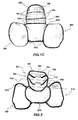
figures 1A to 1C are different perspective views of a protection for the neck according to the present invention; -
figure 2 is a front view of paddings, contacted to the wearer's body, of the device offigure 1A ; -
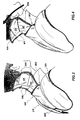
figure 3 is a partially sectional side view of the device according to the present invention once Worn-on; -
figure 4 is a sectional view illustrating the operation of the device according to the present invention; and -
figures 5 and 6 are side views illustrating connections deformable in two different operative positions, details offigure 1A . - Initially referring to
figure 1A . a neck protective device according to the present invention comprises at least twoprotective elements 100, in the present embodiment three in number. - In particular, said protective elements comprise a
central region 101 in a substantially rigid material. - Referring to
figures 2 and3 , thecentral region 101 is fastened to apadding 102 in a material that is substantially soft and therefore easily deformable. - According to a preferred embodiment, the
padding 102 has a greater plane extension with respect to theregions 101, thus defining aperipheral portion 103, which will it also be in a substantially soft material. - Returning to
figure 3 , thecentral regions 101 and thepaddings 102 have a sandwich-like arrangement, so that during the use of the device thepadding 102 be arranged into contact with the user's body, whereas thecentral region 101 faces externally to the body. - Such a configuration allows an improved impact absorption and a high comfort to the user.
- In fact, thus the neck is externally protected by the
region 101 in a rigid material, preventing direct knocks against the user's body, whereas the padding, by being easily deformable, allows to at least partially absorb the energy of an impact. Moreover, such a padding, being of soft material, feels particularly comfortable on the body. - The protective device according to the present invention further comprises supporting means, in particular, in the present embodiment, implemented by supporting
elements - Advantageously, also said supporting elements have features similar to the protective elements, so as to offer a protection also to the body parts respectively covered thereby.
- Alternatively, the supporting means can be implemented by bands, or, always by way of example, be represented by a jacket connecting to the protective elements at the neck.
- Basically, any means allowing to keep the protective elements at the user's neck may be used as supporting means.
- According to the present embodiment, the supporting
elements - Thus, the protective device according to the present invention is particularly susceptible of being integrated in a garment to be used during a sporting activity. Moreover, the supporting elements can also comprise straps, not shown in the figure, apt to allow an improved fastening to the body.
- As it will be detailed hereinafter, the device according to the present invention proves particularly effective; accordingly, an optimal protection could be attained even with a modest padding in the protective elements.
- This feature proves particularly advantageous as it allows the wearability of the device below any jacket, without requiring it to have a special confectioning for the housing of the device.
- Hence, the device can conveniently be inserted in a garment exclusively during a sporting activity, and removed afterwards.
- In order to allow an easy wearability of the device, and the entailed removal thereof, the supporting elements have a curvature such as to adapt onto shoulders and shoulder blades.
- This feature allows to alternatively wear the protective device merely below a jacket or other garment, with no need of additional fastening.
- In fact, said shape allows to accurately position the device; the garment, as long as sufficiently clinging to the body, stably keeps such a position.
- Concerning the operation of the device, returning to
figures 1A-1C , theprotective elements 100 are connected thereamong by connectingmeans 300 allowing in particular the mutual rotation of theprotective elements 100, and working as hinge. According to a preferred embodiment, said means 300 is made withdeformable elements 301. - Such deformable elements are fastened at side ends of the
protective elements 100. In particular, referring tofigure 1B , said location enables said connecting means to allow the rotation of eachprotective element 100 with respect to respective axes ofrotation - Moreover, as illustrated in
figures 1C and 2 , theprotective elements 100 have partially overlappedends 104, so as to assure a continuous protection at the user's neck, avoiding the presence of openings that could allow a direct impact of the latter with any obstacles or with the ground itself. - The
ends 104 will hereinafter be denoted by the adjective "overlapped", indicating that they are overlapped to a further protective element. It is understood that the same definition indicates likewise the case in which it is had an inverted arrangement with the protective elements above the ends. During the rotation allowed by saidconnecting means 300, theprotective elements 100 always remain overlapped therebetween, thereby providing a continuous protection in all operative configurations. - Such a feature is implemented with a suitable arrangement of the axes of
rotation overlapped ends 104, which during the rotation of theprotective elements 100 could be subjected to limited displacements, so as to keep below the respective protective elements. - However, the motion of the
protective elements 100 is such as to assure the mobility required during the different sport activities and that the protections for the neck according to the known art cannot effectively assure. - Firstly, in fact, the mutual rotation of the
protective elements 100 allows the backward tilting of the neck. - This motion is required, e.g., during motor bike activities in which the driver, owing to the driving posture, has to tilt back the neck, so as to raise the head and have a better vision of the road.
- Or, another instance in which such a protection proves particularly useful is in case of skiing, above all at amateur level where in particular complete freedom of motion and comfort are required.
- However, the backward tilting motion cannot be carried out by a mere rotation of the protective elements, as the presence of overlapped ends 104 hampers their free rotation.
- In order to allow this motion, the connecting means 300 conveniently comprises
deformable connections 301, allowing, besides a mutual rotation between the protective elements about theaxes - In the present embodiment the deformable connections are a strip-
like element 301, fastened at theperipheral portion 103, basically joining the protective element at said side ends. - Moreover, according to the present embodiment, the strip-
like element 301, made e.g. with a strip of fabric, extends along the entire perimeter of the protection, both in the external region and in that contacting the user's body, thereby enveloping together the protective elements, as well as the supporting elements, and implementing said connectingmeans 300. - It has to be noted that the main motion that should be carried out by the device is the mutual rotation between the protective elements along the
axes - During said motion, the strip-
like element 301 bends, as highlighted infigure 4 , yet this action not only implements the mutual rotation of theprotective elements 100, but also those limited rotations with respect to different axes and/or limited translation motions nearing thereto and/or away therefrom. - By means of said limited motions, essentially allowing to arrange the relative position of the
protective elements 100 the one with respect to the other, it is possible to attain the abovedescribed working configurations, so that theprotective elements 100 always keep partially overlapped at the ends 104. - The strip-like elements are essentially made of a flexible material, e.g. of synthetic fabrics, and require no particular elasticity, since the deformability itself enables the abovedescribed combination of motions.
- Moreover, the shape of the strip-like elements could differ from that of the mere plane strip, e.g. by preceding a central rib for higher resistance, in particular when heavier loads are envisaged, in case of particularly extreme activities.
- Moreover, the connecting means 300 thus implemented allow limited lateral tilting motions of the head, by virtue of the flexibility of the
deformable connections 301. This feature proves particularly advantageous as it provides a high freedom of motion during sport activities, while always assuring a complete protection to the neck. Such effectiveness is not only related to the fact that also in this case it is kept the overlapping of the elements and the entailed continuity in the protection, but also to the fact that the device allows to limit the side tilting motions, thereby avoiding hazardous hyperextensions of the neck. - During the motions of mutual rotation about the
axes protective elements 100 slide the one against the other. - In other words, since, as mentioned above, the shape of the protective elements and the positioning of the axes of rotation is such as not to allow a free rotation if not by slight deformations of the connecting means 300, during said rotations the overlapped ends 104 are not free to move, but their motion is hampered by the presence of the protective element thereabove.
- Hence, while the rotation is possible, the motion occurs with the concomitant contact of the
ends 104 against theprotective elements 100, in particular at theperipheral portions 103 and at thepaddings 102. This constructive feature becomes evident observing the location of respective centers ofrotation axes figures 3 and 4 . In fact, owing to this position the path undergone by theprotective elements 100 interferes with theends 104, causing the contact thereof. Such a contact does not inhibit the rotation of the elements, due to the deformability of theconnections 301, of theends 104 and of thepaddings 102, yet it limits the maximum range of the neck during the backward tilting. - In fact, with the increasing of the rotation between the protective elements, the resistance provided by the overlapped ends increases, as there increases the interference with the protective element to which it is overlapped. Hence, neither the
deformable connections 301 norperipheral portions 103 andpaddings 102 are capable of deforming sufficiently to let the tilting motion of the neck advance, beyond a certain angle. - Moreover, such a feature is shown in
figure 4 in which it is described the operation of the protective device according to the present invention with the neck tilted backward. - The possibility of limiting such motions, while not completely inhibiting them, again proves particularly advantageous since a backward hyperextension of the neck, substantially the classic motion called "whiplash", can have dire consequences as potentially prejudicial to the spine.
- The protective device according to the present invention not only limits such motions, but also provides a dampening thereof.
- In fact, also the overlapped ends preferably comprise a
peripheral portion 103 in a deformable material that, during the rotation of the protective elements, is gradually deformed, optionally along with thepadding 102, dissipating the energy that in case of impact tends to shift the neck backward. - Moreover, referring to
figure 4 and always according to a preferred embodiments, the protective elements have a variable thickness, in particular theoverlapped end 104 has a flattened shape. - Alternatively, the
protective elements 100 can have a substantially wedge-shaped cross section. - Basically, such a flat shape can be implemented gradually making said wedge-shaped section.
- Thus, besides the dampening effect created by the deformation of the
peripheral portion 103 and of thepadding 102, also the gradual wedging of a protective element with respect to that overlapped during their mutual rotation, at the flat zone, allows to exert a gradual resistance to motion. - Such a resistance can also be implemented by means of a particular configuration of the protective elements extending in a surface having a radius of curvature different with respect to that defined by the rotation of the overlapped ends 104. In the simplest case the protective elements can develop along a substantially plane surface; however, according to a preferred embodiment, they advantageously have a concavity such as to facilitate the wedging of the protective elements in the abovedescribed manner.
- Moreover, the presence of a portion of protective element with a flattened shape allows also a greater stability of the protective device when worn-on, in particular when the neck is in a straight position.
- Again referring to
figures 1A ad 1C, the above-described connectingmeans 300 is used also at the connection between the protective elements and the supporting elements, and between the supporting elements themselves. - Moreover, thus a further axis of
rotation 403 is defined, between protective elements and the supportingelement 201. - Thus, the same freedom of motion implemented for the neck is substantially implemented also at the portion joining neck and back and near the shoulder blades. These features allow a high wearability, thereby making the protective device according to the present invention easily wearable under a jacket.
- Moreover, they foster a high freedom of movements, jointly to the protection for back and shoulders, which proves particularly useful during sport activities.
- Always by virtue of the use of the connecting means 300 also at the supporting elements, 201 and 202, the invention allows to provide a support for the neck, as the use of the structure formed by supporting elements and protective elements prevents the weight of the head from bearing entirely onto the neck.
- In fact, the feature of limiting or anyhow containing neck motions proves particularly useful to provide a support to the neck also under non-traumatic conditions. Always by way of example, during motor biking practice the device according to the present invention can provide support to the neck and head during a normal ride, just because it limits the backward tilting of said body parts, advantageously providing the possibility of relaxing the neck muscles.
- Likewise for back and shoulders, the protective device according to the present invention may be combined and optionally fastened with other protective elements, e.g. in correspondence of the breast, or of a helmet.
- The present invention has hereto been described with reference to preferred embodiments thereof. It is understood that there may be other embodiments referable to the same inventive concept, all falling within the protective scope of the claims set forth hereinafter.
Claims (10)
- A neck protective device, comprising- at least two protective elements (100), said at least two protective elements (100) being partially overlapped and comprising respective overlapped ends (104),- supporting means (200) of said at least two protective elements (100), and- respective connecting means (300) of said at least two protective elements (100),wherein said connecting means (300) is apt to allow the mutual rotation of said at least two protective elements (100), working as hinges along respective axes of rotation (401, 402), in a manner such that said at least two protective elements (100) slide the one against the other during said mutual rotation and said overlapped ends (104) interfere with said at least two protective elements (100) limiting said mutual rotation,
characterized in that said connecting means (300) comprises deformable connections (301) between said protective elements (100), so that the connecting means (300) allows, besides said mutual rotation, also additional rotations according to different axes, which are different from said respective axes of rotation (401, 402), and/or limited translation motions nearing thereto and/or away therefrom, said connecting means (300) being fastened to a substantially soft peripheral portion (103) of said protective elements (100). - The protective device according to the preceding claim, wherein said at least two protective elements (100) have a flattened shape at said overlapped ends (104).
- The protective device according to one of the preceding claims, wherein said protective elements (100) extend along a surface having a radius of curvature different with respect to that defined by the rotation of said overlapped ends (104).
- The protective device according to one of the preceding claims, wherein said protective elements (100) have a substantially wedge-shaped cross section.
- The protective device according to one of the preceding claims, wherein said at least two protective elements (100) comprise a substantially rigid central region (101) and a padding (102), assembled in a sandwich-like configuration.
- The protective device according to the preceding claim, wherein said padding (102) has a greater plane extension with respect to said central region (101), thus defining said peripheral portion (103).
- The protective device according to one of the preceding claims, wherein said connecting means (300) is fastened at side ends of said at least two protective elements (100).
- The protective device according to one of the preceding claims, wherein said overlapped ends remain overlapped to said protective elements (100) during said motion of rotation about said axes (401, 402).
- The protective device according to one of the preceding claims, wherein said supporting means (200) comprises supporting elements (201, 202) suitable for the protection of shoulders and back.
- The protective device according to one of the preceding claims, wherein said protective elements (100) are rotatably connected to said supporting means (200).
Applications Claiming Priority (3)
| Application Number | Priority Date | Filing Date | Title |
|---|---|---|---|
| ITRM20040572 ITRM20040572A1 (en) | 2004-11-22 | 2004-11-22 | BIOMECHANICAL PROTECTION DEVICE. |
| ITRM20050350 ITRM20050350A1 (en) | 2005-07-01 | 2005-07-01 | NECK PROTECTION DEVICE. |
| PCT/IB2005/053866 WO2006054274A1 (en) | 2004-11-22 | 2005-11-22 | Neck protective device |
Publications (2)
| Publication Number | Publication Date |
|---|---|
| EP1838398A1 EP1838398A1 (en) | 2007-10-03 |
| EP1838398B1 true EP1838398B1 (en) | 2011-01-26 |
Family
ID=35999444
Family Applications (2)
| Application Number | Title | Priority Date | Filing Date |
|---|---|---|---|
| EP05819209A Expired - Lifetime EP1838398B1 (en) | 2004-11-22 | 2005-11-22 | Neck protective device |
| EP05820502A Expired - Lifetime EP1838399B1 (en) | 2004-11-22 | 2005-11-22 | Protective device |
Family Applications After (1)
| Application Number | Title | Priority Date | Filing Date |
|---|---|---|---|
| EP05820502A Expired - Lifetime EP1838399B1 (en) | 2004-11-22 | 2005-11-22 | Protective device |
Country Status (6)
| Country | Link |
|---|---|
| US (2) | US7979922B2 (en) |
| EP (2) | EP1838398B1 (en) |
| AT (2) | ATE496661T1 (en) |
| DE (2) | DE602005025932D1 (en) |
| ES (1) | ES2356829T3 (en) |
| WO (2) | WO2006054273A1 (en) |
Cited By (1)
| Publication number | Priority date | Publication date | Assignee | Title |
|---|---|---|---|---|
| US10441870B2 (en) | 2017-05-05 | 2019-10-15 | Aexos Inc. | Protective articles and methods thereof |
Families Citing this family (16)
| Publication number | Priority date | Publication date | Assignee | Title |
|---|---|---|---|---|
| US20090064385A1 (en) * | 2005-03-21 | 2009-03-12 | Med-Eng Systems Inc. | Head and neck protector |
| US20090048550A1 (en) * | 2007-08-18 | 2009-02-19 | Silikids Llc | Knee pads for children and method of manufacture |
| US8621666B2 (en) * | 2009-02-04 | 2014-01-07 | Lineweight Llc | Garment protective assembly |
| ES2368227B2 (en) * | 2009-07-14 | 2012-04-26 | Fundacion Cidaut | NECK PROTECTOR. |
| CN101912674B (en) * | 2010-07-27 | 2012-07-04 | 罗红元 | Human body integral elastic sport mode integrator |
| US20120240317A1 (en) * | 2011-03-21 | 2012-09-27 | Richard Diamond | Protective athletic garment |
| US20120240303A1 (en) * | 2011-03-22 | 2012-09-27 | Bengie Molina Matta | Leg/shin guard knee pad |
| US8393017B2 (en) * | 2011-08-09 | 2013-03-12 | Brady Sheren Designs Inc. | Apparatus to be worn on an individual's chest below a full face helmet to limit the occurrence of cervical spinal cord injuries in the event of a crash |
| US20130239310A1 (en) * | 2012-03-16 | 2013-09-19 | Brian Charles Flug | Anti-concussion compression, survibility and sustainbilty safty device for the neck and spine |
| US9913501B1 (en) | 2012-03-16 | 2018-03-13 | Athletek Sports Safety Gear Llc | Methods of reducing impact forces and injuries using a synthetic neck muscle system |
| GB2505487B (en) * | 2012-08-31 | 2018-09-12 | The Royal United Hospitals Bath Nhs Found Trust | Cervical neck brace |
| JP6077029B2 (en) * | 2015-02-17 | 2017-02-08 | 株式会社二子商事 | Elbow guard |
| US20170006929A1 (en) * | 2015-07-07 | 2017-01-12 | Brent Bourgeois | Articulated Tripartite Elbow-and-Knee-Area Protection |
| IT201600099201A1 (en) * | 2016-10-04 | 2018-04-04 | Abe Sport Group S R L | PROTECTIVE COLLAR, IN PARTICULAR FOR BIKERS, AND HEAD OF CLOTHING INCLUDING THE PROTECTIVE COLLAR |
| US10368594B1 (en) * | 2018-03-28 | 2019-08-06 | Normand P. LaCroix | Stabilized support device for a limb guard |
| US11523927B2 (en) | 2018-08-17 | 2022-12-13 | Todd Douglas Deetsch | Head and neck support apparatus |
Family Cites Families (16)
| Publication number | Priority date | Publication date | Assignee | Title |
|---|---|---|---|---|
| CA1118952A (en) * | 1979-04-25 | 1982-03-02 | Tony Johnston | Throat guard |
| US4325148A (en) * | 1980-04-23 | 1982-04-20 | Canada Cycle And Motor Company Limited | Uniforms for ice hockey players |
| US5060314A (en) * | 1990-04-03 | 1991-10-29 | The United States Of America As Represented By The Secretary Of The Navy | Multi-mission ballistic resistant jacket |
| US5123408A (en) | 1991-09-18 | 1992-06-23 | Gaines Leonard F | Sports helmet braced for protection of the cervical spine |
| JP3809912B2 (en) * | 1992-12-21 | 2006-08-16 | ジョゼフ エッチ. ウエスト | Protective clothing |
| CA2093264C (en) * | 1993-04-02 | 1998-07-14 | Leif Skottheim | Limb protector |
| DE19631121C2 (en) * | 1996-08-01 | 1998-12-17 | Schramm Sport Gmbh Kwon Kampfs | Protective padding for the foot and shin of a person, especially an athlete |
| US6305031B1 (en) | 1998-06-12 | 2001-10-23 | Armadillo Sports Design Limited | Protective appliance |
| GB2345436A (en) | 1999-01-09 | 2000-07-12 | Standard Co Ltd Ag | Tray for supporting drinks on a bar counter |
| GB2345435A (en) * | 1999-01-09 | 2000-07-12 | Connor Edward O | Spine guard |
| US6308345B1 (en) | 1999-12-06 | 2001-10-30 | James D. Williams, Jr. | Headrest for workers, belayers or physically impaired persons |
| US6178556B1 (en) * | 2000-07-17 | 2001-01-30 | Parker Athletic Products, Llc | Custom-fitted catcher's leg guard and method |
| JP2002030502A (en) * | 2000-07-19 | 2002-01-31 | Futaba Packing Co Ltd | Sportswear and shock-absorbing part |
| ITTV20010113A1 (en) * | 2001-08-10 | 2003-02-10 | Alpinestars Res Srl | FREELY JOINTED PROTECTION DEVICE AGAINST BACK IMPACTS |
| US6738984B2 (en) * | 2001-10-29 | 2004-05-25 | Sherry S. Gillen | Protective body vest |
| US20040060100A1 (en) | 2002-09-30 | 2004-04-01 | Reiterman Donald R. | Neck protector |
-
2005
- 2005-11-22 EP EP05819209A patent/EP1838398B1/en not_active Expired - Lifetime
- 2005-11-22 US US11/791,207 patent/US7979922B2/en not_active Expired - Fee Related
- 2005-11-22 WO PCT/IB2005/053865 patent/WO2006054273A1/en not_active Ceased
- 2005-11-22 WO PCT/IB2005/053866 patent/WO2006054274A1/en not_active Ceased
- 2005-11-22 DE DE602005025932T patent/DE602005025932D1/en not_active Expired - Lifetime
- 2005-11-22 DE DE602005026174T patent/DE602005026174D1/en not_active Expired - Lifetime
- 2005-11-22 AT AT05819209T patent/ATE496661T1/en not_active IP Right Cessation
- 2005-11-22 ES ES05820502T patent/ES2356829T3/en not_active Expired - Lifetime
- 2005-11-22 AT AT05820502T patent/ATE494934T1/en not_active IP Right Cessation
- 2005-11-22 EP EP05820502A patent/EP1838399B1/en not_active Expired - Lifetime
- 2005-11-22 US US11/791,206 patent/US20080201831A1/en not_active Abandoned
Cited By (1)
| Publication number | Priority date | Publication date | Assignee | Title |
|---|---|---|---|---|
| US10441870B2 (en) | 2017-05-05 | 2019-10-15 | Aexos Inc. | Protective articles and methods thereof |
Also Published As
| Publication number | Publication date |
|---|---|
| ATE496661T1 (en) | 2011-02-15 |
| ATE494934T1 (en) | 2011-01-15 |
| ES2356829T3 (en) | 2011-04-13 |
| US20080201831A1 (en) | 2008-08-28 |
| EP1838399B1 (en) | 2011-01-12 |
| EP1838399A1 (en) | 2007-10-03 |
| EP1838398A1 (en) | 2007-10-03 |
| US7979922B2 (en) | 2011-07-19 |
| WO2006054273A1 (en) | 2006-05-26 |
| US20070289051A1 (en) | 2007-12-20 |
| DE602005026174D1 (en) | 2011-03-10 |
| WO2006054274A1 (en) | 2006-05-26 |
| DE602005025932D1 (en) | 2011-02-24 |
Similar Documents
| Publication | Publication Date | Title |
|---|---|---|
| US20080201831A1 (en) | Neck Protective Device | |
| US6874170B1 (en) | Head and neck protection system | |
| US7743429B2 (en) | Protective device | |
| US5715541A (en) | Brain and spinal cord protector | |
| US7120941B2 (en) | Crash helmet assembly | |
| US5435007A (en) | Wrist guard | |
| EP2854580B1 (en) | Wearable protection device | |
| US20100268140A1 (en) | Lumbar back brace support member for a back brace support belt | |
| EP0876772B1 (en) | Wrist guard | |
| EP2229828B1 (en) | Wearable protection device | |
| US7975321B1 (en) | Combination neck brace incorporated into a body protector | |
| WO2004062401A2 (en) | Protective eyewear device for sports | |
| WO2013059061A1 (en) | Neck collar | |
| US8370968B2 (en) | Cervical spine protection device | |
| US20240365895A1 (en) | Protective garment for articulations of the human body | |
| CA2942349A1 (en) | Protective headband | |
| ES2358039T3 (en) | NECK PROTECTION DEVICE. | |
| JP2006257615A (en) | Protecting vest and protector | |
| EP3747293B1 (en) | Equipment for neck protection | |
| JP4700458B2 (en) | Head protection | |
| JP3100522U (en) | Backpack | |
| EP3834644B1 (en) | Improved shin guard and related manufacturing process | |
| CN223860243U (en) | Motorcycle knee pad | |
| WO2026093928A1 (en) | Protective garment for articulations of the human body | |
| KR20250165304A (en) | protective helmet |
Legal Events
| Date | Code | Title | Description |
|---|---|---|---|
| PUAI | Public reference made under article 153(3) epc to a published international application that has entered the european phase |
Free format text: ORIGINAL CODE: 0009012 |
|
| 17P | Request for examination filed |
Effective date: 20070622 |
|
| AK | Designated contracting states |
Kind code of ref document: A1 Designated state(s): AT BE BG CH CY CZ DE DK EE ES FI FR GB GR HU IE IS IT LI LT LU LV MC NL PL PT RO SE SI SK TR |
|
| DAX | Request for extension of the european patent (deleted) | ||
| GRAP | Despatch of communication of intention to grant a patent |
Free format text: ORIGINAL CODE: EPIDOSNIGR1 |
|
| GRAS | Grant fee paid |
Free format text: ORIGINAL CODE: EPIDOSNIGR3 |
|
| GRAA | (expected) grant |
Free format text: ORIGINAL CODE: 0009210 |
|
| AK | Designated contracting states |
Kind code of ref document: B1 Designated state(s): AT BE BG CH CY CZ DE DK EE ES FI FR GB GR HU IE IS IT LI LT LU LV MC NL PL PT RO SE SI SK TR |
|
| REG | Reference to a national code |
Ref country code: GB Ref legal event code: FG4D |
|
| REG | Reference to a national code |
Ref country code: CH Ref legal event code: EP |
|
| REG | Reference to a national code |
Ref country code: IE Ref legal event code: FG4D |
|
| REF | Corresponds to: |
Ref document number: 602005026174 Country of ref document: DE Date of ref document: 20110310 Kind code of ref document: P |
|
| REG | Reference to a national code |
Ref country code: DE Ref legal event code: R096 Ref document number: 602005026174 Country of ref document: DE Effective date: 20110310 |
|
| REG | Reference to a national code |
Ref country code: ES Ref legal event code: FG2A Ref document number: 2358039 Country of ref document: ES Kind code of ref document: T3 Effective date: 20110420 |
|
| REG | Reference to a national code |
Ref country code: NL Ref legal event code: VDEP Effective date: 20110126 |
|
| LTIE | Lt: invalidation of european patent or patent extension |
Effective date: 20110126 |
|
| PG25 | Lapsed in a contracting state [announced via postgrant information from national office to epo] |
Ref country code: IS Free format text: LAPSE BECAUSE OF FAILURE TO SUBMIT A TRANSLATION OF THE DESCRIPTION OR TO PAY THE FEE WITHIN THE PRESCRIBED TIME-LIMIT Effective date: 20110526 Ref country code: PT Free format text: LAPSE BECAUSE OF FAILURE TO SUBMIT A TRANSLATION OF THE DESCRIPTION OR TO PAY THE FEE WITHIN THE PRESCRIBED TIME-LIMIT Effective date: 20110526 Ref country code: LV Free format text: LAPSE BECAUSE OF FAILURE TO SUBMIT A TRANSLATION OF THE DESCRIPTION OR TO PAY THE FEE WITHIN THE PRESCRIBED TIME-LIMIT Effective date: 20110126 Ref country code: GR Free format text: LAPSE BECAUSE OF FAILURE TO SUBMIT A TRANSLATION OF THE DESCRIPTION OR TO PAY THE FEE WITHIN THE PRESCRIBED TIME-LIMIT Effective date: 20110427 Ref country code: LT Free format text: LAPSE BECAUSE OF FAILURE TO SUBMIT A TRANSLATION OF THE DESCRIPTION OR TO PAY THE FEE WITHIN THE PRESCRIBED TIME-LIMIT Effective date: 20110126 Ref country code: SE Free format text: LAPSE BECAUSE OF FAILURE TO SUBMIT A TRANSLATION OF THE DESCRIPTION OR TO PAY THE FEE WITHIN THE PRESCRIBED TIME-LIMIT Effective date: 20110126 |
|
| PG25 | Lapsed in a contracting state [announced via postgrant information from national office to epo] |
Ref country code: NL Free format text: LAPSE BECAUSE OF FAILURE TO SUBMIT A TRANSLATION OF THE DESCRIPTION OR TO PAY THE FEE WITHIN THE PRESCRIBED TIME-LIMIT Effective date: 20110126 Ref country code: AT Free format text: LAPSE BECAUSE OF FAILURE TO SUBMIT A TRANSLATION OF THE DESCRIPTION OR TO PAY THE FEE WITHIN THE PRESCRIBED TIME-LIMIT Effective date: 20110126 Ref country code: BG Free format text: LAPSE BECAUSE OF FAILURE TO SUBMIT A TRANSLATION OF THE DESCRIPTION OR TO PAY THE FEE WITHIN THE PRESCRIBED TIME-LIMIT Effective date: 20110426 Ref country code: SI Free format text: LAPSE BECAUSE OF FAILURE TO SUBMIT A TRANSLATION OF THE DESCRIPTION OR TO PAY THE FEE WITHIN THE PRESCRIBED TIME-LIMIT Effective date: 20110126 Ref country code: PL Free format text: LAPSE BECAUSE OF FAILURE TO SUBMIT A TRANSLATION OF THE DESCRIPTION OR TO PAY THE FEE WITHIN THE PRESCRIBED TIME-LIMIT Effective date: 20110126 Ref country code: FI Free format text: LAPSE BECAUSE OF FAILURE TO SUBMIT A TRANSLATION OF THE DESCRIPTION OR TO PAY THE FEE WITHIN THE PRESCRIBED TIME-LIMIT Effective date: 20110126 Ref country code: CY Free format text: LAPSE BECAUSE OF FAILURE TO SUBMIT A TRANSLATION OF THE DESCRIPTION OR TO PAY THE FEE WITHIN THE PRESCRIBED TIME-LIMIT Effective date: 20110126 Ref country code: BE Free format text: LAPSE BECAUSE OF FAILURE TO SUBMIT A TRANSLATION OF THE DESCRIPTION OR TO PAY THE FEE WITHIN THE PRESCRIBED TIME-LIMIT Effective date: 20110126 |
|
| PG25 | Lapsed in a contracting state [announced via postgrant information from national office to epo] |
Ref country code: EE Free format text: LAPSE BECAUSE OF FAILURE TO SUBMIT A TRANSLATION OF THE DESCRIPTION OR TO PAY THE FEE WITHIN THE PRESCRIBED TIME-LIMIT Effective date: 20110126 Ref country code: DK Free format text: LAPSE BECAUSE OF FAILURE TO SUBMIT A TRANSLATION OF THE DESCRIPTION OR TO PAY THE FEE WITHIN THE PRESCRIBED TIME-LIMIT Effective date: 20110126 |
|
| PG25 | Lapsed in a contracting state [announced via postgrant information from national office to epo] |
Ref country code: SK Free format text: LAPSE BECAUSE OF FAILURE TO SUBMIT A TRANSLATION OF THE DESCRIPTION OR TO PAY THE FEE WITHIN THE PRESCRIBED TIME-LIMIT Effective date: 20110126 Ref country code: RO Free format text: LAPSE BECAUSE OF FAILURE TO SUBMIT A TRANSLATION OF THE DESCRIPTION OR TO PAY THE FEE WITHIN THE PRESCRIBED TIME-LIMIT Effective date: 20110126 Ref country code: CZ Free format text: LAPSE BECAUSE OF FAILURE TO SUBMIT A TRANSLATION OF THE DESCRIPTION OR TO PAY THE FEE WITHIN THE PRESCRIBED TIME-LIMIT Effective date: 20110126 |
|
| PLBE | No opposition filed within time limit |
Free format text: ORIGINAL CODE: 0009261 |
|
| STAA | Information on the status of an ep patent application or granted ep patent |
Free format text: STATUS: NO OPPOSITION FILED WITHIN TIME LIMIT |
|
| 26N | No opposition filed |
Effective date: 20111027 |
|
| REG | Reference to a national code |
Ref country code: DE Ref legal event code: R097 Ref document number: 602005026174 Country of ref document: DE Effective date: 20111027 |
|
| PG25 | Lapsed in a contracting state [announced via postgrant information from national office to epo] |
Ref country code: MC Free format text: LAPSE BECAUSE OF NON-PAYMENT OF DUE FEES Effective date: 20111130 |
|
| REG | Reference to a national code |
Ref country code: CH Ref legal event code: PL |
|
| PG25 | Lapsed in a contracting state [announced via postgrant information from national office to epo] |
Ref country code: CH Free format text: LAPSE BECAUSE OF NON-PAYMENT OF DUE FEES Effective date: 20111130 Ref country code: LI Free format text: LAPSE BECAUSE OF NON-PAYMENT OF DUE FEES Effective date: 20111130 |
|
| REG | Reference to a national code |
Ref country code: IE Ref legal event code: MM4A |
|
| PG25 | Lapsed in a contracting state [announced via postgrant information from national office to epo] |
Ref country code: IE Free format text: LAPSE BECAUSE OF NON-PAYMENT OF DUE FEES Effective date: 20111122 |
|
| PG25 | Lapsed in a contracting state [announced via postgrant information from national office to epo] |
Ref country code: LU Free format text: LAPSE BECAUSE OF NON-PAYMENT OF DUE FEES Effective date: 20111122 |
|
| PG25 | Lapsed in a contracting state [announced via postgrant information from national office to epo] |
Ref country code: TR Free format text: LAPSE BECAUSE OF FAILURE TO SUBMIT A TRANSLATION OF THE DESCRIPTION OR TO PAY THE FEE WITHIN THE PRESCRIBED TIME-LIMIT Effective date: 20110126 |
|
| PG25 | Lapsed in a contracting state [announced via postgrant information from national office to epo] |
Ref country code: HU Free format text: LAPSE BECAUSE OF FAILURE TO SUBMIT A TRANSLATION OF THE DESCRIPTION OR TO PAY THE FEE WITHIN THE PRESCRIBED TIME-LIMIT Effective date: 20110126 |
|
| REG | Reference to a national code |
Ref country code: GB Ref legal event code: 732E Free format text: REGISTERED BETWEEN 20150813 AND 20150819 |
|
| REG | Reference to a national code |
Ref country code: FR Ref legal event code: PLFP Year of fee payment: 11 |
|
| REG | Reference to a national code |
Ref country code: ES Ref legal event code: PC2A Owner name: DAINESE, S.PA Effective date: 20160113 |
|
| PGFP | Annual fee paid to national office [announced via postgrant information from national office to epo] |
Ref country code: GB Payment date: 20151118 Year of fee payment: 11 Ref country code: DE Payment date: 20151119 Year of fee payment: 11 Ref country code: IT Payment date: 20151104 Year of fee payment: 11 |
|
| PGFP | Annual fee paid to national office [announced via postgrant information from national office to epo] |
Ref country code: ES Payment date: 20151111 Year of fee payment: 11 Ref country code: FR Payment date: 20151119 Year of fee payment: 11 |
|
| REG | Reference to a national code |
Ref country code: FR Ref legal event code: TP Owner name: DAINESE S.P.A., IT Effective date: 20160205 |
|
| REG | Reference to a national code |
Ref country code: DE Ref legal event code: R119 Ref document number: 602005026174 Country of ref document: DE |
|
| GBPC | Gb: european patent ceased through non-payment of renewal fee |
Effective date: 20161122 |
|
| REG | Reference to a national code |
Ref country code: FR Ref legal event code: ST Effective date: 20170731 |
|
| PG25 | Lapsed in a contracting state [announced via postgrant information from national office to epo] |
Ref country code: FR Free format text: LAPSE BECAUSE OF NON-PAYMENT OF DUE FEES Effective date: 20161130 Ref country code: IT Free format text: LAPSE BECAUSE OF NON-PAYMENT OF DUE FEES Effective date: 20161122 |
|
| PG25 | Lapsed in a contracting state [announced via postgrant information from national office to epo] |
Ref country code: DE Free format text: LAPSE BECAUSE OF NON-PAYMENT OF DUE FEES Effective date: 20170601 Ref country code: GB Free format text: LAPSE BECAUSE OF NON-PAYMENT OF DUE FEES Effective date: 20161122 |
|
| PG25 | Lapsed in a contracting state [announced via postgrant information from national office to epo] |
Ref country code: ES Free format text: LAPSE BECAUSE OF NON-PAYMENT OF DUE FEES Effective date: 20161123 |
|
| REG | Reference to a national code |
Ref country code: ES Ref legal event code: FD2A Effective date: 20181122 |