EP1838004A1 - Method, system and radio station for interference cancellation - Google Patents
Method, system and radio station for interference cancellation Download PDFInfo
- Publication number
- EP1838004A1 EP1838004A1 EP06005752A EP06005752A EP1838004A1 EP 1838004 A1 EP1838004 A1 EP 1838004A1 EP 06005752 A EP06005752 A EP 06005752A EP 06005752 A EP06005752 A EP 06005752A EP 1838004 A1 EP1838004 A1 EP 1838004A1
- Authority
- EP
- European Patent Office
- Prior art keywords
- radio station
- radio
- station
- baseband signal
- signal
- Prior art date
- Legal status (The legal status is an assumption and is not a legal conclusion. Google has not performed a legal analysis and makes no representation as to the accuracy of the status listed.)
- Withdrawn
Links
Images


Classifications
-
- H—ELECTRICITY
- H04—ELECTRIC COMMUNICATION TECHNIQUE
- H04B—TRANSMISSION
- H04B1/00—Details of transmission systems, not covered by a single one of groups H04B3/00 - H04B13/00; Details of transmission systems not characterised by the medium used for transmission
- H04B1/06—Receivers
- H04B1/10—Means associated with receiver for limiting or suppressing noise or interference
- H04B1/12—Neutralising, balancing, or compensation arrangements
- H04B1/123—Neutralising, balancing, or compensation arrangements using adaptive balancing or compensation means
- H04B1/126—Neutralising, balancing, or compensation arrangements using adaptive balancing or compensation means having multiple inputs, e.g. auxiliary antenna for receiving interfering signal
Definitions
- the invention concerns a method for detecting a first baseband signal sent by a first sending station via an air interface to a first radio station of a radio communications system as well as a respective first radio station and a respective radio communications system.
- MIMO multiple-input multiple-output
- HSDPA High Speed Downlink Packet Access
- SDMA space-division multiple access
- the multi-user multi cell scenario can be regarded as a generalized MIMO channel, where terminal antennas form the inputs and the antennas at multiple base stations the outputs.
- the centralized service area concept suffers from high complexity. In principle, the larger a service area the larger the complexity and, of course, the more interference can be cancelled inside the service area. Previous investigations showed however that the service area concept works fine inside a service area but the same problems as for single cells without coordination arise now on a larger scale at the boundaries of the service area.
- the service area concept requires interconnections with high data rate to transport the signals from all base stations to one central unit where a computationally complex problem must be solved. Note that the complexity rises at least with the third order of the number of base stations involved. It is not taken into account that at some locations only little interference may be present. This is handled in the same manner as high interference.
- scenario C In A. Vanelli-Coralli, R. Padovani, J. Hou, J. E. Smee, "Capacity of Cell Clusters with Coordinated Processing", USCD Inaugural workshop on Information theory and it's applications", La Jolla, CA, Feb. 6-10, 2006 , the service area concept is denoted as scenario C.
- the object is achieved by a method for detecting a first baseband signal, a radio station and a radio communications system according to independent claims.
- the inventive method for detecting a first baseband signal sent by a first sending station via an air interface to a first radio station of a radio communications system whereas a first receive signal, which contains the first baseband signal superposed with at least a second baseband signal sent by a second sending station to a second radio station, is received by the first radio station.
- the first radio station uses at least a second receive signal received by the second radio station for detection of the first baseband signal, whereas the second receive signal contains at least the second baseband signal, by at least partially cancelling the interference in the first receive signal caused by the second baseband signal.
- pilot sequence additionally identifies the second radio station as serving radio station of the second sending station.
- the second radio can send an identifier of the second sending station, e.g. a MAC-ID (Medium Access Control-Identifier), identifying the second sending station.
- the second sending station can alternatively send an identifier of the second radio station, identifying the second radio station.
- the second receive signal is used for detecting the first baseband signal if a reception power of the pilot sequence is greater or equal to a threshold and/or if its use reduces a residual interference contained in a detection signal which results when detecting the first baseband signal from the first receive signal.
- a meshed network is used to connect the first radio station and the at least second radio station.
- the first radio station and the at least second radio station are part of the same mesh.
- the second receive signal is received at the first radio station via a broadcast message broadcasted by the second radio station.
- the second receive signal is advantageously requested by the first radio station from the second radio station.
- the second receive signal contains pilot sequences of sending stations whose baseband signals are contained in the second receive signal, whereas the pilot sequences are usable for channel estimation.
- the inventive radio communications system comprises a first radio station and at least a second radio station, both having all means necessary to perform the inventive method.
- the inventive first radio station for a radio communications system comprises means for detecting a first baseband signal sent by a first sending station via an air interface to the first radio station and means for receiving a first receive signal, whereas the first receive signal contains the first baseband signal superposed with at least a second baseband signal sent by a second sending station to a second radio station, and according to the invention the means for detecting the first baseband signal are configured to use at least a second receive signal received by the second radio station for detection of the first baseband signal, whereas the second receive signal contains at least the second baseband signal, by at least partially cancelling the interference in the first receive signal caused by the second baseband signal.
- the first radio station further provides all means necessary to perform the inventive method.
- a sending station is for example a terminal of a radio communications system.
- a terminal is for instance a mobile radio terminal, particularly a mobile phone or a flexible of fixed device, for transmission of picture data and/or sound data, for fax, short message service (SMS) messages and/or E-mail messages, and/or for internet access.
- SMS short message service
- a communications system is for example a computer network or a radio communications system.
- Radio communications systems are systems in which a data transmission between terminals is performed over an air interface.
- the data transmission can be both bidirectional and unidirectional.
- Radio communications systems are particularly cellular radio communication systems, e.g. according to the GSM (Global System for Mobile Communications) standard or the UMTS (Universal Mobile Telecommunication System) standard.
- GSM Global System for Mobile Communications
- UMTS Universal Mobile Telecommunication System
- Radio communication systems are also wireless local area networks (WLAN) according to standards from the Institute of Electrical and Electronics Engineers (IEEE) like 802. 11a-i, HiperLAN1 and HiperLAN2 (High Performance Radio Local Area Network) as well as Bluetooth-Networks.
- WLAN wireless local area networks
- FIG 1 shows an example of a decentralized meshed service area (DMSA) concept.
- a meshed backbone network is proposed for the DMSA.
- Each node i.e. each base station
- Each node contains the intelligence needed for local interference reduction.
- a first sending station M1 is assigned to a first radio station BS1 and a second sending station M2 is assigned to a second radio station.
- the first sending station M1 transmits a first baseband signal S to the first radio station BS1.
- the first baseband signal S is also received by at least the second radio station BS2.
- the second sending station M2 transmits a second baseband signal I 2 to the second radio station BS2.
- the second baseband signal I 2 is also received by at least the first radio station BS2.
- Figure 1 additionally shows seven radio stations B connected via a meshed network with each other and with the first radio station and the second radio station.
- the signal processing is distributed across the network and not centralized in a single central unit.
- Each radio station has the capability to spatially separate signals from multiple sending stations.
- the number of locally separable streams should be larger than the number of physical antennas at a radio station.
- each radio station could have two own antennas but the signal processing capability to separate six signals of sending stations.
- FIG. 2 schematically shows the first radio station BS1 as an example for the configuration of a radio station.
- the first radio station BS1 has two own antennas, two radio frontends RF1, RF2, and two analog-to-digital converters AD1, AD2.
- the signals are converted from parallel to serial p/s and the serial streams are modulated e/o onto optical signals operating at two wavelengths ⁇ 1 and ⁇ 2 .
- optical cross connect OXC these signals are multiplexed onto an optical transport fibre OTF through which all radio stations in a mesh are connected.
- the optical cross connect OXC may also be connected to other fibres from other meshes.
- the first radio station BS1 Over the optical transport fibre OTF, the first radio station BS1 has access to the received signals from adjacent radio stations.
- the relevant optical signals are coupled out, converted o/e both in the electrical domain and then from serial to parallel s/p. Finally, they are read into a joint detection unit JD, together with the signals received at the first radio station.
- the joint detection unit JD has means in each receive branch to estimate the channels not only within the cell served by the first radio station, but also from sending stations in adjacent cells.
- first sending station M1 and the second sending station M2 which are assigned to the same resource (e.g. frequency and/or code and/or time slot) in both cells which is assumed to create inter-cell interference.
- the first sending station M1 and the second sending station M2 both transmit pilot sequences which do not only identify their own antenna or antennas but also the cell, i.e. the radio station, to which they are assigned.
- each serving radio station e.g. the first radio station and the second radio station in Figure 1
- the serving radio station may involve the received signals from the so identified adjacent radio stations and separates the desired signal of a sending station from the interference using the multi-stream separation capability of its joint detection unit.
- the first radio station BS1 wishes to detect the first baseband signal S having the channel H 11 .
- the reception of the first baseband signal S is disturbed by the second baseband signal I 2 .
- H 12 is the channel through which the interfering second baseband signal I 2 is received.
- the first radio station BS1 has already estimated the interference channel H 12 and hence it knows that the second sending station M2 is assigned to the second radio station BS2.
- the channel coefficients H 21 and H 22 could be signalled by the second radio station separately from the second receive signal Y 2 .
- the adjacent radio stations B and BS2 could be configured to transmit their receive signals if requested by the first radio station BS1.
- V-BLAST ordered successive interference cancellation
- sphere decoding maximum likelihood detection.
- the first radio station BS1 estimates the channel coefficients also for sending stations served by other radio stations.
- the first radio station BS1 always has a selection of possible input signals to be used for the interference cancellation. This is called antenna selection in the literature. But unlike for antenna selection in MIMO systems, the number of sources (sending stations, having e.g. several antennas and sending baseband signals) for which the interference should be cancelled becomes uncertain when the system load is high.
- the first radio station BS1 is able to identify radio stations to which interfering sending stations are connected.
- the first radio station BS1 includes receive signals from corresponding radio stations and estimates the channels (arranged in the matrix H ) between interfering sending stations and the corresponding radio stations. But these receive signals might contain additional interference.
- the third baseband signal adds additional power for the detection of the first baseband signal as well. This already increases the SIR.
- the well-known macro diversity gains are related to this, and they are implicitly included in the full or partial interference cancellation described here.
- the second term includes the interference that cannot be cancelled. It is not possible to completely remove the interference and to detect the first baseband signal S without interference as it was possible in the special case shown in equations (1) to (4). Instead a reconstructed baseband signal having residual interference can be calculated.
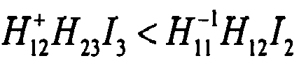
- Equation (7) gives a better result than equation (8) if the following relation is valid for the terms representing the residual interference: H 12 + ⁇ H 23 ⁇ I 3 ⁇ H 11 - 1 ⁇ H 12 ⁇ I 2
- the respective equations are not shown. Before actually using one of the options for detecting the first baseband signal S, one must always take care that the partial interference cancellation has led to improved signal quality.
- the interference is partially cancelled for the first N interferers with a usual MIMO algorithm based on the partial matrix H 1:N,1:N and the partial vector (S I 2 ... IN) T while the signal of the other interferers is considered as additive noise. It is possible to take the covariance of this "noise" into account in the signal processing. As observed in (7), the other interferers result in an additional distortion of the desired signal after the partial interference cancellation.
- a bottom-up approach is proposed how new radio stations are potentially involved in the interference cancellation process. Start with the strongest interferers already identified at the first radio station BS1 and take the radio stations serving these interferers at first into account. Each extra radio station adds another receive signal but potentially also one or more new dimensions of interferers. For each new antenna, the desired first baseband signal S is reconstructed using the partial interference cancellation algorithm described above and the residual variance of the interference is compared to the best previous results to make a decision whether it is useful to include this new antenna or not. This is repeated until no more new radio stations are available that reduce the residual interference.
- any ordering of the antennas of all radio stations is considered and the one offering the best interference cancellation is used. In practise, this might be not feasible and another ordering can be used as a compromise.
- the underlying meshed backbone network can be realized.
- it can be realized using optical fibre, cable, microwave and free-space optical links.
- WDM wavelength-division multiplexing
- This is depicted in principle in Figure 3, showing the first radio station BS1, the second radio station BS2, a third radio station BS3 and a fourth radio station BS4 as well as the first sending station M1 and the second sending station M2.
- the logical meshes in Figure 1 are realized using an optical fibre ring, which is well established in metropolitan area fibre networks.
- the receive signal from each antenna of the radio stations is modulated on another wavelength such that it is available to all other radio stations in the same mesh.
- each radio station has an optical cross connect OXC which essentially contains at least one wavelength splitting and combining device known as arrayed waveguide grating (AWG).
- the optical cross connect OXC enables two functionalities: Firstly, it enables access to the receive signals from other radio stations within the mesh. Secondly it enables random access to the receive signals from radio stations connected to adjacent meshes.
- a block of multiple wavelengths is assigned to each mesh. Over each optical cross connect OXC, the wavelength group of an adjacent mesh can be coupled in and multicast in the current mesh such that each radio station gets direct access to the signals from adjacent meshes as well.
- the total number of wavelength in a dense WDM system can be 100 or more. This allows even the use of multiple antennas at each radio station, if some reuse of wavelengths is done in distant meshes. This can be realized using the add-drop functionality of the arrayed waveguide grating.
- IP Internet Protocol
- a time stamp will be additionally attached to receive signals which are transmitted to a radio station on request, e.g. to the first radio station BS1.
- the second radio station BS2 when receiving a request for the second receive signal, e.g. from the first radio station BS1, stores in a memory an identifier of the first radio station BS1 and an identifier of the first sending station M1 and/or identifiers of other sending stations of which baseband signals are contained in the second receive signal and/or the respective identifiers of radio stations to which the other sending stations are assigned, the identifiers being e.g. contained in the second receive signal of the second radio station BS2.
- the first radio station to which the first sending station M1 is attached whenever the second radio station BS2 detects, e.g. in its receive signal, the same interference constellation - i.e. the same combination of identifiers of sending stations, which might additionally be assigned to the same radio stations as detected in connection with the second receive signal. Due to this advanced transmission of receive signals the number of time consuming requests of receive signals can be reduced. This advanced transmission of receive signals is especially useful if a sending station has to transmit a high amount of data, so that the probability for the same interference constellation is high.
- the radio stations When using an IP-network the radio stations include means adapted to work with IP. This means can be build in a radio station alternatively or additionally to the components needed for optical networks according to figure 2.
- each sending station is surrounded by its own service area, i.e. service area is now a sending-station-centric term.
- a sending station is assigned to the radio station where it is received with the strongest signal power.
- the service area of a sending station is defined by the radio stations providing receive signals needed to suppress the interference in the best possible way.
- the handover occurs inside the serving radio station, in this example the first radio station BS1, and it causes a reconfiguration of the local MIMO signal processing used for the partial interference cancellation. In principle, no new protocol is needed for this.
- the serving radio station just switches another set of inputs to the multi-stream signal processing shown in Figure 2.
- each radio station broadcasts at which time and on which resources it is going to schedule all sending stations served in its cell.
- each of the surrounding radio stations may organize its interference cancellation in advance.
- the receive signals of radio stations serving potentially interfering sending stations can be automatically included in the multi-stream signal processing used for the local interference reduction, which is called service area handover prediction.
Landscapes
- Engineering & Computer Science (AREA)
- Computer Networks & Wireless Communication (AREA)
- Signal Processing (AREA)
- Mobile Radio Communication Systems (AREA)
Abstract
Description
- The invention concerns a method for detecting a first baseband signal sent by a first sending station via an air interface to a first radio station of a radio communications system as well as a respective first radio station and a respective radio communications system.
- In recent years, much research has been conducted on multiple-input multiple-output (MIMO) systems and a large number of algorithms have been developed, mostly for wireless LAN (Local Area Network) and partly for cellular radio communication systems. They have been proposed to support a single terminal with multiple antennas (as in MIMO WLAN or HSDPA [High Speed Downlink Packet Access]) or to support multiple terminals, both from a single base station with multiple antennas (which is called space-division multiple access, SDMA). These approaches can partly be used to cancel interference provided that there are unused degrees of freedom, i.e. less terminal antennas than base station antennas.
- When for instance in the up-link terminals and base stations are well synchronized and the channels between all terminals and base stations are known, the multi-user multi cell scenario can be regarded as a generalized MIMO channel, where terminal antennas form the inputs and the antennas at multiple base stations the outputs.
- It is well known under the term service area concept that joint transmission and detection of user signals controlled by a central unit can cancel the interference within a service area - which consists of two or more base stations - completely. In the ideal case of so-called "writing on dirty paper" inter-cell interference can be cancelled without any performance degradation.
- The centralized service area concept suffers from high complexity. In principle, the larger a service area the larger the complexity and, of course, the more interference can be cancelled inside the service area. Previous investigations showed however that the service area concept works fine inside a service area but the same problems as for single cells without coordination arise now on a larger scale at the boundaries of the service area.
- The service area concept requires interconnections with high data rate to transport the signals from all base stations to one central unit where a computationally complex problem must be solved. Note that the complexity rises at least with the third order of the number of base stations involved. It is not taken into account that at some locations only little interference may be present. This is handled in the same manner as high interference.
- In X. Tao, C. Tang, Z. Dai, X. Xu, B. Liu, P.Zhang "Capacity Analysis for a Generalized Distributed Antenna Architecture for Beyond 3G Systems" in Proc. VTC Spring 2005, Stockholm, Sweden, Vol. 5, pp. 3193 - 3196, a sliding group-cell concept has been proposed in which a central unit has been used. When a terminal moves through a service area, the central unit forms subgroups of cells for joint transmission and detection in order to reduce the complexity. When the terminal is mobile, the position is tracked and new subgroups are formed.
- In A. Vanelli-Coralli, R. Padovani, J. Hou, J. E. Smee, "Capacity of Cell Clusters with Coordinated Processing", USCD Inaugural workshop on Information theory and it's applications", La Jolla, CA, Feb. 6-10, 2006, the service area concept is denoted as scenario C.
- An object of the present invention is to provide an improved method for cancelling interference in up-link transmissions in a radio communications system, which can be implemented with less complexity than methods used in service area concepts. It is a further object of the invention to provide a respective radio station as well as a respective radio communications system.
- The object is achieved by a method for detecting a first baseband signal, a radio station and a radio communications system according to independent claims.
- Advantageous embodiments are subject matter of dependent claims.
- According to the inventive method for detecting a first baseband signal sent by a first sending station via an air interface to a first radio station of a radio communications system, whereas a first receive signal, which contains the first baseband signal superposed with at least a second baseband signal sent by a second sending station to a second radio station, is received by the first radio station. The first radio station uses at least a second receive signal received by the second radio station for detection of the first baseband signal, whereas the second receive signal contains at least the second baseband signal, by at least partially cancelling the interference in the first receive signal caused by the second baseband signal.
- Advantageously, a pilot sequence sent by the second sending station is received at the first radio station, the pilot sequence identifying the second sending station (M2) and being usable for channel estimation.
- It is further useful if the pilot sequence additionally identifies the second radio station as serving radio station of the second sending station.
- Alternatively, the second radio can send an identifier of the second sending station, e.g. a MAC-ID (Medium Access Control-Identifier), identifying the second sending station. Further the second sending station can alternatively send an identifier of the second radio station, identifying the second radio station.
- Advantageously, the second receive signal is used for detecting the first baseband signal if a reception power of the pilot sequence is greater or equal to a threshold and/or if its use reduces a residual interference contained in a detection signal which results when detecting the first baseband signal from the first receive signal.
- In one embodiment a meshed network is used to connect the first radio station and the at least second radio station.
- Advantageously, the first radio station and the at least second radio station are part of the same mesh.
- Computational could be further reduced, if the first radio station only considers receive signals of radio stations being part of the same mesh as the first radio station.
- Advantageously, the second receive signal is received at the first radio station via a broadcast message broadcasted by the second radio station.
- Especially if at least the part of the network containing the first radio station and the second radio station is organized using the Internet Protocol, the second receive signal is advantageously requested by the first radio station from the second radio station.
- Advantageously, the second receive signal contains pilot sequences of sending stations whose baseband signals are contained in the second receive signal, whereas the pilot sequences are usable for channel estimation.
- The inventive radio communications system comprises a first radio station and at least a second radio station, both having all means necessary to perform the inventive method.
- The inventive first radio station for a radio communications system, comprises means for detecting a first baseband signal sent by a first sending station via an air interface to the first radio station and means for receiving a first receive signal, whereas the first receive signal contains the first baseband signal superposed with at least a second baseband signal sent by a second sending station to a second radio station, and according to the invention the means for detecting the first baseband signal are configured to use at least a second receive signal received by the second radio station for detection of the first baseband signal, whereas the second receive signal contains at least the second baseband signal, by at least partially cancelling the interference in the first receive signal caused by the second baseband signal.
- Advantageously, the first radio station further provides all means necessary to perform the inventive method.
- In the following the invention is described according to embodiments shown in figures:
- Fig. 1
- meshed network showing an example of the inventive method,
- Fig. 2
- a schematic example of an inventive radio station,
- Fig. 3
- a schematic drawing of an inventive radio communications system using a meshed network, and
- Fig. 4
- schematic drawing of a service-area handover using service areas according to the invention
- A sending station is for example a terminal of a radio communications system.
- A radio station is for example a base station of a radio communications system.
- A terminal is for instance a mobile radio terminal, particularly a mobile phone or a flexible of fixed device, for transmission of picture data and/or sound data, for fax, short message service (SMS) messages and/or E-mail messages, and/or for internet access.
- The invention can advantageously be used in any kind of communications system. A communications system is for example a computer network or a radio communications system.
- Radio communications systems are systems in which a data transmission between terminals is performed over an air interface. The data transmission can be both bidirectional and unidirectional. Radio communications systems are particularly cellular radio communication systems, e.g. according to the GSM (Global System for Mobile Communications) standard or the UMTS (Universal Mobile Telecommunication System) standard.
- Also future mobile radio communications systems, e.g. according to the fourth generation, as well as ad-hoc-networks shall be understood as radio communication systems. Radio communication systems are also wireless local area networks (WLAN) according to standards from the Institute of Electrical and Electronics Engineers (IEEE) like 802. 11a-i, HiperLAN1 and HiperLAN2 (High Performance Radio Local Area Network) as well as Bluetooth-Networks.
- Figure 1 shows an example of a decentralized meshed service area (DMSA) concept. A meshed backbone network is proposed for the DMSA. Each node (i.e. each base station) contains the intelligence needed for local interference reduction. In figure 1 a first sending station M1 is assigned to a first radio station BS1 and a second sending station M2 is assigned to a second radio station. The first sending station M1 transmits a first baseband signal S to the first radio station BS1. The first baseband signal S is also received by at least the second radio station BS2. The second sending station M2 transmits a second baseband signal I2 to the second radio station BS2. The second baseband signal I2 is also received by at least the first radio station BS2. Figure 1 additionally shows seven radio stations B connected via a meshed network with each other and with the first radio station and the second radio station.
- According to the invention the signal processing is distributed across the network and not centralized in a single central unit. Each radio station has the capability to spatially separate signals from multiple sending stations. However, the number of locally separable streams should be larger than the number of physical antennas at a radio station. For instance, each radio station could have two own antennas but the signal processing capability to separate six signals of sending stations.
- Figure 2 schematically shows the first radio station BS1 as an example for the configuration of a radio station. The first radio station BS1 has two own antennas, two radio frontends RF1, RF2, and two analog-to-digital converters AD1, AD2. After the analog-to-digital converters AD1, AD2, the signals are converted from parallel to serial p/s and the serial streams are modulated e/o onto optical signals operating at two wavelengths λ1 and λ2. Using an optical cross connect OXC, these signals are multiplexed onto an optical transport fibre OTF through which all radio stations in a mesh are connected. The optical cross connect OXC may also be connected to other fibres from other meshes.
- Over the optical transport fibre OTF, the first radio station BS1 has access to the received signals from adjacent radio stations. The relevant optical signals are coupled out, converted o/e both in the electrical domain and then from serial to parallel s/p. Finally, they are read into a joint detection unit JD, together with the signals received at the first radio station. The joint detection unit JD has means in each receive branch to estimate the channels not only within the cell served by the first radio station, but also from sending stations in adjacent cells.
- Consider as an example the first sending station M1 and the second sending station M2 which are assigned to the same resource (e.g. frequency and/or code and/or time slot) in both cells which is assumed to create inter-cell interference. Now the first sending station M1 and the second sending station M2 both transmit pilot sequences which do not only identify their own antenna or antennas but also the cell, i.e. the radio station, to which they are assigned.
- Generally, based on this information, each serving radio station, e.g. the first radio station and the second radio station in Figure 1, can estimate the channel coefficients of the desired and of the interfering sending stations. From the outputs of the corresponding correlation circuit bench, which is part of each receive branch in the respective joint detection unit, the serving radio station identifies also to which radio station the interfering sending stations are assigned to.
- In order to remove the interference, the serving radio station may involve the received signals from the so identified adjacent radio stations and separates the desired signal of a sending station from the interference using the multi-stream separation capability of its joint detection unit.
- As shown in Fig. 1 the first radio station BS1 wishes to detect the first baseband signal S having the channel H11. The reception of the first baseband signal S is disturbed by the second baseband signal I2. A first receive signal Y1 at the first radio station BS1, neglecting noise, is given as

- Where H12 is the channel through which the interfering second baseband signal I2 is received. In a correlator bank, the first radio station BS1 has already estimated the interference channel H12 and hence it knows that the second sending station M2 is assigned to the second radio station BS2.
- From receive signals of adjacent radio stations B and BS2, which broadcast their receive signals, it picks out a second receive signal from the second radio station BS2

in which pilot sequences are embedded which are used to estimate channel coefficients H21 and H22 in the joint signal detection unit JD. Additionally, an identifier of a time slot during which the second receive signal Y2 was received by the second radio station BS2 can be provided together with the second receive signal Y2. - Alternatively the channel coefficients H21 and H22 could be signalled by the second radio station separately from the second receive signal Y2. Further instead of broadcasting their receive signals, the adjacent radio stations B and BS2 could be configured to transmit their receive signals if requested by the first radio station BS1.
- Equations (1) and (2) can be written conveniently in matrix form

- Now the first radio station BS1 has all information needed to cancel the inter-cell interference I2 out of the first receive signal Y1. Equation (3) states a conventional MIMO problem which can be solved by a number of well known algorithms, among which the zero forcing using the pseudo-inverse of the matrix H denoted as H+

- The first baseband signal S can be separated the better the more orthogonal the column and row vectors of the channel matrix H in (3) are and the more independent linear combinations of the same baseband signals are involved in the interference cancellation. This is called spatial diversity.
- In general however, it is a complex task to select the right radio stations and sending stations needed to reduce the interference. As mentioned above, the first radio station BS1 estimates the channel coefficients also for sending stations served by other radio stations. Hence, the first radio station BS1 always has a selection of possible input signals to be used for the interference cancellation. This is called antenna selection in the literature. But unlike for antenna selection in MIMO systems, the number of sources (sending stations, having e.g. several antennas and sending baseband signals) for which the interference should be cancelled becomes uncertain when the system load is high.
- Starting from the first receive signal Y1, the first radio station BS1 is able to identify radio stations to which interfering sending stations are connected. Next the first radio station BS1 includes receive signals from corresponding radio stations and estimates the channels (arranged in the matrix H) between interfering sending stations and the corresponding radio stations. But these receive signals might contain additional interference.
- Mathematically this is described so that the matrix H may have more columns than rows


- While the quadratic matrices in (5) and (5a) may be invertible, there is always a residual baseband signal which results in unavoidable interference. Due to these residual terms, decentralized interference cancellation is often imperfect. But a partial interference cancellation is always practical and the target is not perfect but the best possible interference cancellation.
- Note that the third baseband signal adds additional power for the detection of the first baseband signal as well. This already increases the SIR. The well-known macro diversity gains are related to this, and they are implicitly included in the full or partial interference cancellation described here.
- In order to reduce the interference in (5) at least partially, one can write

- The second term includes the interference that cannot be cancelled. It is not possible to completely remove the interference and to detect the first baseband signal S without interference as it was possible in the special case shown in equations (1) to (4). Instead a reconstructed baseband signal having residual interference can be calculated. The reconstructed baseband signal Ŝ reads

- The residual interference is possibly smaller than without (partial) interference cancellation. Without interference cancellation the baseband signal reconstructed from Y1, given by (1), is:

- Equation (7) gives a better result than equation (8) if the following relation is valid for the terms representing the residual interference:
- A third possible reconstruction equivalently results from (5a) and removes interference from the third baseband signal I3. The respective equations are not shown. Before actually using one of the options for detecting the first baseband signal S, one must always take care that the partial interference cancellation has led to improved signal quality.
- There are three possibilities to detect the first baseband signal S, i.e. a reconstructed baseband signal if interference can not be completely cancelled:
- 1. Live with the interference as it is (equation (8)).
- 2. Remove interference from the second baseband signal I2 and live with additional interference due to the third baseband signal I 3 (equation (7)).
- 3. Remove interference from the third baseband signal I 3 and live with additional interference due to the second baseband signal I 2 .
- All options have to be considered and the one with the highest effective signal-to-interference ratio is selected. This can be continued using signals from further radio stations. Hence we get additional rows in the matrix H such that it may become invertible and the interference can be fully cancelled. But as above it is uncertain whether these additional baseband signals help or hurt, since potentially new interferers could get involved as well. Finding the right radio stations for cooperation turns out to be a complex optimization problem for which the optimal strategy is similar as described above but formulated below with a more general mathematics.
- Let us assume that we have N-1 radio stations the baseband signals of which are accessible to the first radio station BS1 and that the total number of sending stations visible to (being received by) all radio stations is M.

- When N ≤ M, this is a standard MIMO problem which can be solved with the well known MIMO detection schemes such that inter-cell interference is fully cancelled. But when N>M, the interference cannot be perfectly cancelled. The task is then to minimize the residual interference of the sources the interference of which cannot be cancelled.
- Let us consider a heuristic partial interference cancellation strategy. For intuition it is assumed that the interferers (i.e. baseband signals of sending stations, received e.g. by the first radio station BS1) are arranged in descending order of the Euclidean norms of their respective columns in the matrix H. In this way, the total interference power from the surplus interferers is minimized. This is of course suboptimal since one does not take into account the effect of this interference after the joint detection which would be optimal but requires that all variations of the interfering sources are considered until the best selection is found.
- Whatever approach is used, the separation into cancelled interferers and others can be described as


- Now the interference is partially cancelled for the first N interferers with a usual MIMO algorithm based on the partial matrix H1:N,1:N and the partial vector (S I2 ... IN)T while the signal of the other interferers is considered as additive noise. It is possible to take the covariance of this "noise" into account in the signal processing. As observed in (7), the other interferers result in an additional distortion of the desired signal after the partial interference cancellation.
- A bottom-up approach is proposed how new radio stations are potentially involved in the interference cancellation process. Start with the strongest interferers already identified at the first radio station BS1 and take the radio stations serving these interferers at first into account. Each extra radio station adds another receive signal but potentially also one or more new dimensions of interferers. For each new antenna, the desired first baseband signal S is reconstructed using the partial interference cancellation algorithm described above and the residual variance of the interference is compared to the best previous results to make a decision whether it is useful to include this new antenna or not. This is repeated until no more new radio stations are available that reduce the residual interference.
- The order in which new radio stations are involved may also have an effect on the decision. In the optimal way, any ordering of the antennas of all radio stations is considered and the one offering the best interference cancellation is used. In practise, this might be not feasible and another ordering can be used as a compromise.
- In the following an example is given how the underlying meshed backbone network can be realized. There are various options. In principle it can be realized using optical fibre, cable, microwave and free-space optical links. But it is certainly preferable to use a fixed optical fibre network based on wavelength-division multiplexing (WDM) technique. This is depicted in principle in Figure 3, showing the first radio station BS1, the second radio station BS2, a third radio station BS3 and a fourth radio station BS4 as well as the first sending station M1 and the second sending station M2. The logical meshes in Figure 1 are realized using an optical fibre ring, which is well established in metropolitan area fibre networks. The receive signal from each antenna of the radio stations is modulated on another wavelength such that it is available to all other radio stations in the same mesh.
- Moreover, each radio station has an optical cross connect OXC which essentially contains at least one wavelength splitting and combining device known as arrayed waveguide grating (AWG). The optical cross connect OXC enables two functionalities: Firstly, it enables access to the receive signals from other radio stations within the mesh. Secondly it enables random access to the receive signals from radio stations connected to adjacent meshes.
- A block of multiple wavelengths is assigned to each mesh. Over each optical cross connect OXC, the wavelength group of an adjacent mesh can be coupled in and multicast in the current mesh such that each radio station gets direct access to the signals from adjacent meshes as well. The total number of wavelength in a dense WDM system can be 100 or more. This allows even the use of multiple antennas at each radio station, if some reuse of wavelengths is done in distant meshes. This can be realized using the add-drop functionality of the arrayed waveguide grating.
- Alternatively or combined with the optical meshed network it is possible to use a network based on the Internet Protocol (IP). In this case, using connections between radio stations based on IP, a receive signal of a radio station would be transferred to another radio station on request instead of broadcasting to save transmission resources, because IP-networks provide less bandwidth and therefore higher latency than optical networks.
- In case that an IP network is used to connect the different radio stations the delay for data transmission is unpredictable. To assure that the correct signals are combined for interference cancellation a time stamp will be additionally attached to receive signals which are transmitted to a radio station on request, e.g. to the first radio station BS1.
- To minimize data traffic on the limited bandwidth of an IP backbone and to reduce processing delay which would result in unwanted user latency, it is useful that for example the second radio station BS2 when receiving a request for the second receive signal, e.g. from the first radio station BS1, stores in a memory an identifier of the first radio station BS1 and an identifier of the first sending station M1 and/or identifiers of other sending stations of which baseband signals are contained in the second receive signal and/or the respective identifiers of radio stations to which the other sending stations are assigned, the identifiers being e.g. contained in the second receive signal of the second radio station BS2. This allows the second radio station BS2 to automatically transmit a receive signal to a radio station, e.g. the first radio station, to which the first sending station M1 is attached whenever the second radio station BS2 detects, e.g. in its receive signal, the same interference constellation - i.e. the same combination of identifiers of sending stations, which might additionally be assigned to the same radio stations as detected in connection with the second receive signal. Due to this advanced transmission of receive signals the number of time consuming requests of receive signals can be reduced. This advanced transmission of receive signals is especially useful if a sending station has to transmit a high amount of data, so that the probability for the same interference constellation is high.
- When using an IP-network the radio stations include means adapted to work with IP. This means can be build in a radio station alternatively or additionally to the components needed for optical networks according to figure 2.
- It is important to note what the term service area actually means in this decentralized infrastructure compared to the centralized concept. Actually, each sending station is surrounded by its own service area, i.e. service area is now a sending-station-centric term. A sending station is assigned to the radio station where it is received with the strongest signal power. The service area of a sending station is defined by the radio stations providing receive signals needed to suppress the interference in the best possible way.
- In this context, it may be of interest to mention a particular form of a handover (called service-area handover) which can occur for a given sending station. The difference to the conventional handover is shown in Figure 4. In the conventional inter-cell handover (right), another radio station B' becomes responsible for the detection of a sending station MS instead of a radio station B. For this, a conventional protocol can be used.
- A service area handover from a first service area r1 consisting of the first radio station BS1 and the second radio station BS2 to a second service area r2, consisting of the first radio station BS1, the third radio station BS3 and the fourth radio station BS4, occurs when it is more suitable to change the set of cooperating radio stations needed to detect a desired baseband signal so that the residual interference is minimized. Such service area handover might happen particularly when a new sending station M' becomes active in an adjacent cell. In order to cancel the suddenly rising interference, the receive signal from the radio station serving the interfering sending station, e.g. the third radio station BS3, must be included in the interference cancellation process of adjacent radio stations.
- The handover occurs inside the serving radio station, in this example the first radio station BS1, and it causes a reconfiguration of the local MIMO signal processing used for the partial interference cancellation. In principle, no new protocol is needed for this. The serving radio station just switches another set of inputs to the multi-stream signal processing shown in Figure 2.
- But it could be helpful to establish a broadcast signalling channel over the fibre backbone in which each radio station broadcasts at which time and on which resources it is going to schedule all sending stations served in its cell. Based on this information, each of the surrounding radio stations may organize its interference cancellation in advance. The receive signals of radio stations serving potentially interfering sending stations can be automatically included in the multi-stream signal processing used for the local interference reduction, which is called service area handover prediction.
- As shown above, additional interference included from other sending stations into the receive signal causes a quite complex processing to find the optimum combination of sending stations taken into account for interference cancellation. Besides of the processing overhead this also increases the backbone overhead, which is an important topic for bandwidth limited IP-networks. So a very promising approach is to combine the co-operative detection algorithm with semi-static radio resource management where sending stations with different path loss - resulting in different transmit power - are scheduled in different frequency bands.
- If suitably defined, sending stations transmitting in adjacent radio cells do not interfere with the same power, i.e. worst case interference situations can be avoided. For this reason the first selection of the receive signal is - with high probability - already the best selection avoiding the need for a complex search algorithm.
Claims (12)
- Method for detecting a first baseband signal (S) sent by a first sending station (M1) via an air interface to a first radio station (BS1) of a radio communications system, whereas a first receive signal (Y1), which contains the first baseband signal (S) superposed with at least a second baseband signal (I2) sent by a second sending station (M2) to a second radio station (BS2), is received by the first radio station (BS1),
characterised in that,
the first radio station (BS1) uses at least a second receive signal (Y2) received by the second radio station (BS2) for detection of the first baseband signal (S), whereas the second receive signal (Y2) contains at least the second baseband signal (I2), by at least partially cancelling the interference in the first receive signal (Y1) caused by the second baseband signal (I2). - The method according to claim 1, whereas
a pilot sequence sent by the second sending station (M2) is received at the first radio station (BS1), the pilot sequence identifying the second sending station (M2) and being usable for channel estimation. - The method according to claim 2, whereas
The pilot sequence additionally identifies the second radio station (BS2) as serving radio station of the second sending station (M2). - The method according to claim 2 or 3, whereas
the second receive signal (Y2) is used for detecting the first baseband signal (S) if a reception power of the pilot sequence is greater or equal to a threshold and/or if its use reduces a residual interference contained in a detection signal which results when detecting the first baseband signal (S) from the first receive signal (Y1). - The method according to one of the preceding claims, whereas
a meshed network is used to connect the first radio station (BS1) and the at least second radio station (BS2). - The method according to claim 5, whereas
the first radio station (BS1) and the at least second radio station (BS2) are part of the same mesh. - The method according to claim 6, whereas
the first radio station (BS1) only considers receive signals of radio stations being part of the same mesh as the first radio station (BS1). - The method according to one of the preceding claims, whereas
the second receive signal (Y2) is received at the first radio station (BS1) via a broadcast message broadcasted by the second radio station (BS2). - The method according to one of the preceding claims, whereas
the second receive signal (Y2) contains pilot sequences of sending stations of which baseband signals are contained in the second receive signal (Y2), whereas the pilot sequences are usable for channel estimation. - Radio communications system, comprising
a first radio station (BS1) and at least a second radio station (BS2), both having all means necessary to perform the method according to one of the claims 1-9. - First radio station (BS1) for a radio communications system, comprising- means for detecting a first baseband signal (S) sent by a first sending station (M1) via an air interface to the first radio station (BS1),- means for receiving a first receive signal (Y1), whereas the first receive signal (Y1) contains the first baseband signal (S) superposed with at least a second baseband signal (I2) sent by a second sending station (M2) to a second radio station (BS2),characterised in that,
the means for detecting the first baseband signal (S) are configured to use at least a second receive signal (Y2) received by the second radio station (BS2) for detection of the first baseband signal (S), whereas the second receive signal (Y2) contains at least the second baseband signal (I2), by at least partially cancelling the interference in the first receive signal (Y1) caused by the second baseband signal (I2). - First radio station (BS1) according to claim 11, further providing all means necessary to perform the method according to claims 2-9.
Priority Applications (4)
| Application Number | Priority Date | Filing Date | Title |
|---|---|---|---|
| EP06005752A EP1838004A1 (en) | 2006-03-21 | 2006-03-21 | Method, system and radio station for interference cancellation |
| PCT/EP2007/051231 WO2007107409A1 (en) | 2006-03-21 | 2007-02-08 | Method, system and radio station for interference cancellation |
| CN200780009721.7A CN101479949B (en) | 2006-03-21 | 2007-02-08 | Method, system and radio station for interference cancellation |
| US12/225,436 US8995917B2 (en) | 2006-03-21 | 2007-02-08 | Method, system and radio station for interference cancellation |
Applications Claiming Priority (1)
| Application Number | Priority Date | Filing Date | Title |
|---|---|---|---|
| EP06005752A EP1838004A1 (en) | 2006-03-21 | 2006-03-21 | Method, system and radio station for interference cancellation |
Publications (1)
| Publication Number | Publication Date |
|---|---|
| EP1838004A1 true EP1838004A1 (en) | 2007-09-26 |
Family
ID=36337602
Family Applications (1)
| Application Number | Title | Priority Date | Filing Date |
|---|---|---|---|
| EP06005752A Withdrawn EP1838004A1 (en) | 2006-03-21 | 2006-03-21 | Method, system and radio station for interference cancellation |
Country Status (4)
| Country | Link |
|---|---|
| US (1) | US8995917B2 (en) |
| EP (1) | EP1838004A1 (en) |
| CN (1) | CN101479949B (en) |
| WO (1) | WO2007107409A1 (en) |
Families Citing this family (3)
| Publication number | Priority date | Publication date | Assignee | Title |
|---|---|---|---|---|
| JP4846743B2 (en) * | 2008-02-13 | 2011-12-28 | 日本電信電話株式会社 | Wireless communication system, interference cancellation station, and interference cancellation method |
| US9338031B2 (en) * | 2009-08-17 | 2016-05-10 | Qualcomm Incorporated | Methods and apparatus for interference decrease/cancellation on downlink acquisition signals |
| US9438366B2 (en) * | 2010-02-19 | 2016-09-06 | Qualcomm Incorporated | System access for heterogeneous networks |
Citations (3)
| Publication number | Priority date | Publication date | Assignee | Title |
|---|---|---|---|---|
| EP0766416A2 (en) * | 1995-09-29 | 1997-04-02 | AT&T Corp. | Multiple access cellular communication with signal cancellation to reduce co-channel interference |
| US5799004A (en) * | 1993-10-27 | 1998-08-25 | Nokia Telecommunications | Method for eliminating multiple-access interference and a mobile station |
| US5894500A (en) * | 1997-06-13 | 1999-04-13 | Motorola, Inc. | Method and apparatus for canceling signals in a spread-spectrum communication system |
Family Cites Families (6)
| Publication number | Priority date | Publication date | Assignee | Title |
|---|---|---|---|---|
| MXPA01001753A (en) * | 1998-08-18 | 2002-06-04 | Beamreach Networks Inc | Stacked-carrier discrete multiple tone communication technology. |
| US7454222B2 (en) * | 2000-11-22 | 2008-11-18 | Dragonwave, Inc. | Apparatus and method for controlling wireless communication signals |
| US6842476B2 (en) * | 2001-02-09 | 2005-01-11 | Telefonaktiebolaget Lm Ericsson (Publ) | Co-channel interference canceller |
| US8185075B2 (en) * | 2003-03-17 | 2012-05-22 | Broadcom Corporation | System and method for channel bonding in multiple antenna communication systems |
| US7349411B2 (en) * | 2003-07-30 | 2008-03-25 | Bay Microsystems, Inc. | Economically expansible switching network |
| EP1643657B1 (en) * | 2004-09-30 | 2008-05-14 | NTT DoCoMo, Inc. | Signal detector used in wireless communication system |
-
2006
- 2006-03-21 EP EP06005752A patent/EP1838004A1/en not_active Withdrawn
-
2007
- 2007-02-08 CN CN200780009721.7A patent/CN101479949B/en not_active Expired - Fee Related
- 2007-02-08 WO PCT/EP2007/051231 patent/WO2007107409A1/en not_active Ceased
- 2007-02-08 US US12/225,436 patent/US8995917B2/en not_active Expired - Fee Related
Patent Citations (3)
| Publication number | Priority date | Publication date | Assignee | Title |
|---|---|---|---|---|
| US5799004A (en) * | 1993-10-27 | 1998-08-25 | Nokia Telecommunications | Method for eliminating multiple-access interference and a mobile station |
| EP0766416A2 (en) * | 1995-09-29 | 1997-04-02 | AT&T Corp. | Multiple access cellular communication with signal cancellation to reduce co-channel interference |
| US5894500A (en) * | 1997-06-13 | 1999-04-13 | Motorola, Inc. | Method and apparatus for canceling signals in a spread-spectrum communication system |
Non-Patent Citations (1)
| Title |
|---|
| RANTA P A ET AL: "TDMA cellular network application of an interference cancellation technique", VEHICULAR TECHNOLOGY CONFERENCE, 1995 IEEE 45TH CHICAGO, IL, USA 25-28 JULY 1995, NEW YORK, NY, USA,IEEE, US, vol. 1, 25 July 1995 (1995-07-25), pages 296 - 300, XP010166942, ISBN: 0-7803-2742-X * |
Also Published As
| Publication number | Publication date |
|---|---|
| CN101479949B (en) | 2013-06-12 |
| CN101479949A (en) | 2009-07-08 |
| WO2007107409A1 (en) | 2007-09-27 |
| US20110033186A1 (en) | 2011-02-10 |
| US8995917B2 (en) | 2015-03-31 |
Similar Documents
| Publication | Publication Date | Title |
|---|---|---|
| Mohammadi et al. | Next-generation multiple access with cell-free massive MIMO | |
| CA2141733C (en) | Mobile telecommunication system | |
| JP4416820B2 (en) | Multi-input/output communication method based on distributed sources | |
| JP5451680B2 (en) | Mobile communication terminal | |
| EP2329606B1 (en) | Interference rejection combining for multi-user mimo telecommunications system | |
| US20080268834A1 (en) | Method of grouping users to reduce interference in mimo-based wireless network | |
| JP5117159B2 (en) | Wireless access system, base station apparatus and mobile station apparatus | |
| Jameel et al. | Massive MIMO: A survey of recent advances, research issues and future directions | |
| KR20120014792A (en) | Multiuser Interference Alignment System and Method in Uplink | |
| US9059752B2 (en) | Multicellular cooperative communications in a decentralized network | |
| Dhalbisoi et al. | A comparative analysis on 5G cell free massive MIMO in next generation networking environment | |
| US8995917B2 (en) | Method, system and radio station for interference cancellation | |
| Maso et al. | Channel estimation impact for LTE small cells based on MU-VFDM | |
| US20110275392A1 (en) | Method for Channel Estimation, Base Station and Mobile Node | |
| Chraiti et al. | Spectrum sharing techniques for broadcast cognitive radio networks | |
| JP5520619B2 (en) | Wireless communication method and wireless communication system | |
| Siddiqa et al. | Optimizing spectral efficiency: An SNV scheme for IoT-Enabled CF mMIMO networks | |
| KR20100001678A (en) | Method for cooperative multi-antenna communication | |
| Xiao et al. | A novel opportunistic NOMA scheme for 5G massive MIMO multicast communications | |
| JP4455511B2 (en) | Wireless communication method, wireless communication system, and wireless terminal station | |
| Abu Al-Atta et al. | A comprehensive overview of power domain noma in 5g | |
| KR100984737B1 (en) | Method for cancelling interference signal of base station in a multiuser mimo relay system | |
| KR102107296B1 (en) | Method for aligning interference of multi-user multi-cell mimo channel | |
| JP2007067726A (en) | Wireless repeater, wireless relay method, and wireless relay system | |
| KR101422026B1 (en) | A method for transmitting/receiving signal in a Multiple Input Multiple Output system |
Legal Events
| Date | Code | Title | Description |
|---|---|---|---|
| PUAI | Public reference made under article 153(3) epc to a published international application that has entered the european phase |
Free format text: ORIGINAL CODE: 0009012 |
|
| AK | Designated contracting states |
Kind code of ref document: A1 Designated state(s): AT BE BG CH CY CZ DE DK EE ES FI FR GB GR HU IE IS IT LI LT LU LV MC NL PL PT RO SE SI SK TR |
|
| AX | Request for extension of the european patent |
Extension state: AL BA HR MK YU |
|
| RIN1 | Information on inventor provided before grant (corrected) |
Inventor name: VON HELMOLT, CLEMENS, DR. Inventor name: ZIRWAS, WOLFGANG Inventor name: JUNGNICKEL, VOLKER, DR. Inventor name: HAUSTEIN, THOMAS Inventor name: EICHINGER, JOSEF MARTIN |
|
| RAP3 | Party data changed (applicant data changed or rights of an application transferred) |
Owner name: FRAUNHOFER-GESELLSCHAFT ZUR FOERDERUNG DER ANGEWAN Owner name: NOKIA SIEMENS NETWORKS S.P.A. |
|
| RAP3 | Party data changed (applicant data changed or rights of an application transferred) |
Owner name: FRAUNHOFER-GESELLSCHAFT ZUR FOERDERUNG DER ANGEWAN Owner name: NOKIA SIEMENS NETWORKS GMBH & CO. KG |
|
| AKX | Designation fees paid | ||
| STAA | Information on the status of an ep patent application or granted ep patent |
Free format text: STATUS: THE APPLICATION IS DEEMED TO BE WITHDRAWN |
|
| 18D | Application deemed to be withdrawn |
Effective date: 20080327 |
|
| REG | Reference to a national code |
Ref country code: DE Ref legal event code: 8566 |