EP1837835B1 - Automatic dispenser - Google Patents
Automatic dispenser Download PDFInfo
- Publication number
- EP1837835B1 EP1837835B1 EP05820133A EP05820133A EP1837835B1 EP 1837835 B1 EP1837835 B1 EP 1837835B1 EP 05820133 A EP05820133 A EP 05820133A EP 05820133 A EP05820133 A EP 05820133A EP 1837835 B1 EP1837835 B1 EP 1837835B1
- Authority
- EP
- European Patent Office
- Prior art keywords
- control panel
- merchandise
- box body
- cover
- attached
- Prior art date
- Legal status (The legal status is an assumption and is not a legal conclusion. Google has not performed a legal analysis and makes no representation as to the accuracy of the status listed.)
- Expired - Lifetime
Links
Images







Classifications
-
- G—PHYSICS
- G07—CHECKING-DEVICES
- G07F—COIN-FREED OR LIKE APPARATUS
- G07F5/00—Coin-actuated mechanisms; Interlocks
- G07F5/02—Coin-actuated mechanisms; Interlocks actuated mechanically by coins, e.g. by a single coin
-
- G—PHYSICS
- G07—CHECKING-DEVICES
- G07F—COIN-FREED OR LIKE APPARATUS
- G07F9/00—Details other than those peculiar to special kinds or types of apparatus
- G07F9/10—Casings or parts thereof, e.g. with means for heating or cooling
-
- G—PHYSICS
- G07—CHECKING-DEVICES
- G07F—COIN-FREED OR LIKE APPARATUS
- G07F11/00—Coin-freed apparatus for dispensing, or the like, discrete articles
Definitions
- the present invention relates to a vending machine.
- the present invention relates to a structure for providing a control panel.
- a merchandise discharge apparatus is known from JP-A-2003-123135 , in which a merchandise filled in a capsule (hereinafter referred to as capsule merchandise) is stored in a box and the capsule merchandise is discharged when a predetermined coin is inserted to a coin insertion slot and a handle is rotated ( Fig 3 ).
- a back face of a front panel includes a coin sorting unit. This causes a troublesome operation to detach the coin sorting unit for the maintenance of the coin sorting unit for example.
- the present invention has been made. It is an objective of the present invention an to provide a vending machine that provides an easy maintenance operation of a coin sorting unit or the like.
- US2001010315 describes an article discharging device having a main body with an opening which is provided in a front side, comprising a container for containing and holding an article.
- the container comprises a front wall at least a portion of which is transparent and an article entrance formed in an upper side.
- the container is able to close the opening and the article held in the container can be viewed through the transparent portion of the front wall in a closed state.
- the container can be rotated reciprocally around a predetermined axis, to take the closed state or an article entrance exposed state.
- US3804294 describes a dispensing machine which comprises a housing which is provided with a cover and which contains a removable cash box.
- a merchandise storage member is supported by the housing and is arranged to latch the cover closed.
- Locking structure locks the lid in place and also prevents removal of the storage member. Unlocking the locking structure enables removal of the lid to gain access to the storage member and/or enables the storage member to be shifted to unlatcht the cover and thereby gain access to the cash box.
- a vending machine in which a coin is inserted to cause an operation power is given to a handle to operate a discharge merchandise retention member to discharge a merchandise includes: a box body comprising a front panel having a notch and a control panel including the handle and a coin sorting unit, wherein the control panel has the same shape as the notch and is attached to the box body in a detachable manner so as to be placed in the notch whilst the control panel is attached to box body.
- a coin collection box is provided inside the box body and the coin collection box is externally covered by covering a front face of the coin collection box with the control panel while the control panel is attached to the box body so as to be placed in the notch.
- a side face of the front panel has one of a convex groove or a concave groove
- a side face of the control panel has the other of a convex groove or a concave groove
- the control panel is attached to the box body by sliding a side face of the control panel with a side face of the front panel from the upper side of the notch to engage the convex grove with the concave groove.
- a merchandise filling opening is provided to the upper side of the notch of the box body, a cover is attached with the merchandise filling opening in a detachable manner, the control panel is prevented from moving upward when the cover is attached, and the control panel is allowed to move upward when the cover is detached.
- one of the control panel and the box body has a spring
- the spring allows descent of the control panel to stop at least at a position where the front face of the coin collection box remains exposed
- the control panel and the box body have a locking section that clamps the control panel in a completely depressed state against a biasing force of the spring.
- control panel including the coin sorting unit can be detached from the box, thus realizing an easy maintenance.
- the coin collection box completely covered with the control panel provides secure safety and eliminates the need for a lock for a coin collection box, thus providing a proportional cost reduction.
- control panel that can be slid to be attached to the box body can provide an easy attachment and can allow the control panel to be attached to the box body in a robust manner
- the cover blocks the upward movement of the control panel and thus eliminates a need for a special unit for locking the control panel, thus providing a proportional cost reduction
- the control panel is stopped halfway without being dropped to the lower end of the notch.
- a finger is prevented from being caught by the lower end of the control panel for example.
- the coin collection box can be taken out easily without being obstructed by the control panel.
- a merchandise A filled in a capsule (hereinafter referred to as capsule merchandise A) for example is stored in a box 2.
- capsule merchandise A a merchandise A filled in a capsule
- a person inserts a predetermined coin to a coin insertion slot 3 on a front face of the box 2 and then subsequently rotates a handle 4
- the capsule merchandise A in the box 2 is discharged from a discharge opening 5 provided at the front face of the box 2.
- two boxes 2 are stacked on each other and the bottom of the lower box 2 is attached to a stand including wheels and the upper box 2 has thereon a top panel 10.
- the box 2 includes: a box body 6; a cover 7 for covering a merchandise filling opening 6a of a front face of the box body 6; a control panel 8a that comprises a part of a front panel 8 provided at the lower part of the front face of the box body 6 and that includes a coin sorting unit 9 at the back face; and a top panel 10 covering the upper face of the box body 6.
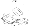
- the cover 7 is made of transparent resin and is formed, as shown in Fig. 3 , to have a concave curved shape to the front side.
- the periphery part of the cover 7 has a wall 11 protruding to the rear side.
- a long hole 12 is provided in a width direction of the box 2.
- Cover 7 includes end walls 11a and side walls 11b.
- the upper end wall l1a of the cover 7 includes small holes 13 formed to sandwich the long hole 12.
- the inner face of the cover 7 has a retainer plate 15 that is also formed to have a curved shape as in the cover 7.
- the retainer plate 15 is attached to a base section of the cover 7 (lower end of curved section) in a rotatable manner.
- the upper end edge of the retainer plate 15 has a pin 16 protruding to the upper side.
- a pull 15a protruding to the rear side is provided.
- the retainer plate 15 and the cover 7 have therebetween a display section 17 (e.g., pop) and the pin 16 is engaged with the small holes 13 of the cover 7 so as to be locked along the cover 7.
- the display section 17 is detached, one hand can grab the cover 7 and the other hand can pull the pull 15a to separate a free end of the retainer plate 15 from the cover 7, thereby detaching the display section 17.
- the lower end of the curved section of the cover 7 has a bending part 14 extending to the lower side.
- the lower edge of the bending part 14 has protrusions 14a at the left and right sides.
- Both side walls sandwiching the merchandise filling opening 6a of the box body 6 are provided by a transparent plate so that the capsule merchandise A in the vending machine can be visually recognized from the lateral side of outside in an oblique direction.
- the inner faces of the both side walls of the box body 6 have, as show in Fig. 4 , a V-like concave part 18a having an opening to the upper side. This concave part 18a is used for the positioning of the cover 7.
- the cover 7 can be appropriately positioned by inserting, while the cover 7 being lowered to the front side of the front face (while the inner face of the cover 7 facing upward), the bending part of the cover 7 into the concave part 18a to cause the front side part of the bending part to be abutted with the front-side wall of the concave part 18a.
- the cover 7 when the cover 7 is raised around the lower edge of the bending part of the cover 7, the rear part of the bending part of the cover 7 is abutted with the wall at the rear side of the concave part 18a.
- This position is a position at which the cover 7 is closed.
- the upper face of the control panel 8a includes a long groove 18b extending in the width direction.
- This long groove 18b is a part that receives the bending part of the cover 7 and that is shaped so that the cover 7 can be raised or lowered.
- the upper face of the control panel 8a includes a locking piece 18c provided at the center in the width direction.
- the upper face of the control panel 8a includes the locking piece 18c.
- This locking piece 18c prevents an upward movement of the closed cover 7. Specifically, when the cover 7 is raised, the lower end of the curved section is inserted to the lower side of the locking piece 18c to prevent the upward movement of the closed cover 7.
- the lower end of the curved section of the cover 7 preferably has a curvature different from those of the other parts of the curved section so that the lower end of the bending part of the cover 7 is appropriately locked by the locking piece 18c.
- the cover 7 when the cover 7 is closed, the protrusion 14a formed at the bending part of the cover 7 is inserted to the lower side of the upper wall of the control panel 8a. As a result, the cover 7 is locked to the control panel 8a. Furthermore, the cover 7 also preferably has a handle at the front face so that the cover 7 can be detached from the box body 6 by being pulled down easily with the handle.
- the box body 6 is structured so that the merchandise filling opening 6a has thereon a lock 19.
- the lock 19 is composed of a lock body 19a and a key 19b.
- the lock body 19a is composed of a cylinder section 19c, a rotor part 19d, and locking pieces 19e and 19f.
- This lock body 19a is retained by an attachment block 19g in a detachable manner. It is noted that, although the locking piece 19e and the locking piece 19f are integrated in this embodiment, the structure is not particularly limited.
- the lock body 19a is attached to the attachment block 19g, the locking pieces 19e and 19f are detached from the lock body 19a in advance. Then, the lock body 19a in this status is pushed into the concave part 19h in front of the attachment block 19g. Then, a lock part (not shown) at the outer periphery of the cylinder section 19c is abutted to the bottom part of the concave part 19b, thus preventing the lock body 19a from being pushed further.
- the bottom of the concave part 19h on the other hand includes a penetration hole having an opening to the rear side of the attachment block 19g.
- a part of the cylinder section 19c protrudes from the rear side of the attachment block 19a.
- This protruded section includes a male screw section 19i that is screwed with a nut 19j.
- the locking pieces 19e and 19f are screwed to the rear end of the rotor part 19d from the rear side of the protruded section.
- the lock body 19a is attached to the attachment block 19g. It is noted that the lock body 19a can be detached from the attachment block 19g in an opposite order of that of the above operation.
- the attachment block 19g is provided with nail pieces 19k and 19k at both sides.
- the box body 6 on the other hand has a concave part 191 that can be engaged with the attachment block 19g.
- the bottom part of the concave part 191 includes holes 19m and 19n.
- the locking pieces 19e and 19f are placed in the lateral direction in advance as shown in Fig. 5(A) .
- the attachment block 19g is engaged into the concave part 191 by inserting the locking pieces 19e and 19f first.
- the locking pieces 19e and 19f and a tip end of one of the nail pieces 19k pass through the hole 19m.
- a tip end of the other nail piece 19k on the other hand passes through the hole 19n.
- protrusions provided at the outer side of the nail pieces 19k, 19k are locked to the back side of the concave part 191 by the elasticity of the nail pieces 19k, 19k.
- the attachment block 19g is attached to the box body 6. It is noted that the attachment block 19g can be detached from the box body 6 by using a hand to push out the attachment block 19g from the inner side of the box body 6 while the locking pieces 19e and 19f being placed in the lateral direction.
- this embodiment has the cover 7 locked to the box body 6 by directly locking the cover 7 by the locking piece 19e of the lock 19
- the box 2 has a movable member that enables a locking position and a lock cancellation position of the cover 7 so that the lock 19 can be used to lock the movable member to the locking position to indirectly lock the cover 7 to the box body 6.
- this embodiment has locked the cover 7 to the box body 6 by inserting the locking piece 19f also into a long hole (not shown)of the upper wall of the box body 6, another structure also may be used in which the locking piece 19e is merely inserted to the long hole 12 of the cover 7.
- another structure also may be used in which, in order to insert the locking piece 19f also to a long hole (not shown) of the upper wall 6b of the box body 6, two upper walls 6b are provided at the upper and lower sides so that the locking piece 19f can be inserted to the long hole of the lower upper wall or the lower side of the upper wall 6b also may have a locking member including a long hole.
- control panel 8a has an inverted L-like shape when seen from the front side.
- the control panel 8a is attached to the box body 6 in a detachable manner.
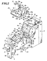
- Fig. 2 shows the control panel 8a detached from the box body 6 and the front panel 8 of the box body 6 has a notch 20 having the same shape as that of the control panel 8a.
- Wall faces at both sides of the control panel 8a have concave grooves 23 arranged in the longitudinal direction with a predetermined interval.
- a wall face for separating the notch 20 in the box body 6 on the other hand has convex grooves 22 arranged in the longitudinal direction with an appropriate interval to the inner side of the width direction.
- control panel 8a In order to attach the control panel 8a to the box body 6, while the cover 7 being detached from the box body 6, the control panel 8a being separated from the bottom of the notch 20 is engaged into the notch 20 from the front face side to slide the control panel 8a in the lower direction to engage the concave grooves 23 with the convex grooves 22 to attach the control panel 8a to a predetermined position of the box body 6.
- the control panel 8a can be detached from the box body 6 on the other hand in an opposite order of that of the above operation.
- the control panel 8a includes a connector (not shown) that can be connected to a connector 6c at the box body 6. These connectors are automatically connected when the control panel 8a is attached to the box body 6 to electrically connect the side of the control panel 8a to the side of the box body 6.
- control panel 8a is formed separately from the box body 6 and the control panel 8a is structured so as to be detachable from the box body 6. This provides not only an easy maintenance of the control panel 8a and but also an easy maintenance of the interior of the box body 6.
- wall faces at the left and right sides of the control panel 8a have locking pieces 8b for retaining the control panel 8 while the control panel 8 having a slight distance from the bottom of the notch 20.
- This locking piece 8b is abutted with a protrusion 8d that is provided at one wall face which forms a part of the notch 20 and is biased by a spring 8c while the control panel 8a being retained to have a slight distance from the bottom of the notch 20.
- the retaining force by this locking piece 8b is not so high. Specifically, the biasing force of the spring 8c toward this locking piece is sufficient to support the weight of the control panel 8a.
- control panel 8a when the control panel 8a is manually depressed in the lower direction, the control panel 8a is moved downward against the biasing force.
- the structure as described above is provided for the purpose of preventing the control panel 8a from jumping down when the control panel 8a is engaged into the box body 6 and for the purpose of allowing a coin collection box 21 (which will be described later) to be drawn while the control panel 8a being positioned to have a slight distance from the bottom of the notch 20.
- the control panel 8a and a partition plate 25 respectively have a locking section 57 for locking the control panel 8a to the box body 6.
- the two sections 57 have the same structure and thus the locking section 57 provided at the partition plate 25 will be exemplarily described.
- the locking section 57 includes a locking pin 57b that operates by the operation of the operation part 57a.
- the locking pin 57b When the control panel 8a is attached to the box body 6 and the operation part 57a of the locking section 57 is operated to protrude the locking pin 57b, the locking pin 57b is positioned at the upper side of the control panel 8a.
- This locking section 57 prevents the upward movement of the control panel 8a.
- the locking section 57 provided at the control panel 8a on the other hand causes the locking pin 57b protruded by the operation of the operation part 57a to be engaged with a concave part (not shown) provided in the box body 6.
- the locking section 57 is not always required to be provided. The reason is that, by attaching the control panel 8a and subsequently attaching the cover 7 to fix the cover 7 to the box body 6 by rotating the key 19b, the upward movement of the control panel 8a is regulated by the cover 7 to prevent the control panel 8a from being detached. However, the existence of the locking section 57 can allow the control panel 8a to be more firmly fixed to the box body 6.
- the box body 6 includes therein the partition plate 25 for partitioning the box body 6 to upper and lower parts.
- the upper part of this partition plate 25 functions as a merchandise storage space 26.
- the partition plate 25 has a circular concave part 27 as shown in Fig. 4 and Fig. 7 .
- the bottom part of the concave part 27 has one merchandise discharge hole 28.
- a discharged article retention member 34 is placed in the concave part 27.
- the bottom part of the concave part 27 also has a next merchandise detection section 70 (which will be described later).
- the bottom part of the concave part 27 also has a rectangular hole 43 for exposing a gear 44.
- the discharge merchandise retention member 34 is composed of a drum 35 and an adapter 37. It is noted that the drum 35 may not always have a regulation plate 36.
- the drum 35 has a plurality of merchandise retention holes 35a (four merchandise retention holes 35a in this embodiment) that retain a merchandise having a relatively large diameter (e.g., a merchandise filled in a capsule) and that are provided in the circumference direction with an identical interval. Furthermore, the drum 35 includes rack teeth 38 at the circumference edge of the lower face. Thus, when the drum 35 is placed on the concave part 27, the rack teeth 38 are meshed with the gear 44. As shown in Fig. 4 , the gear 44 is connected to the handle 4 via an axis 45, the gears 24 and 46, and an axis 4a.
- the rotation power of the handle 4 is transmitted to the drum 35 via the axis 4a, the gears 24 and 46, the axis 45, and the gear 44, and the rack teeth 38, thereby rotating the drum 35.
- one rotation of the handle 4 causes the rotation of the drum 35 in an amount of 360 degrees/(the number of the merchandise retention holes 35a).
- the merchandise retention hole 35a matches the merchandise discharge hole 28 and thus merchandises retained at the merchandise retention hole 35a are discharged one by one.
- the circumference face of the drum 35 has a concave part 39 having the same function as that of ratchet teeth.
- a part of the circumference wall forming the concave part 27 has a rectangular hole 29.
- the rectangular hole 29 has a ratchet piece 30 that has the same function as that of a ratchet nail and that is provided in a retractable manner.
- This ratchet piece 30 is biased in a protrusion direction by a spring (not shown) and the concave part 39 of the drum 35 is engaged with the ratchet piece 30 so that the ratchet piece 30 prevents the inverse rotation of the drum 35.
- the drum 35 includes the regulation plate 36.
- the regulation plate 36 is provided on the drum body.
- the regulation plate 36 is structured to be rotatable around the axis center of the drum 35 in a predetermined angle range.
- This regulation plate 36 has holes 36a in the circumference direction that have the same shapes as those of the merchandise retention holes 35a and that are provided in the same number and pitch of the merchandise retention holes 35a.
- the hole 36a of the regulation plate 36 functions to change, in accordance with the rotation amount of the regulation plate 36, the diameter of the merchandise retention hole 35a.
- a rib 36b for guiding the merchandise at the upper part to the outer side of the radius direction of the drum 35, is disposed upright in the center of the regulation plate 36.
- the rib 36a has four springs 36g that are arranged to the outer side in an oblique upward direction.
- the drum 35 and the regulation plate 36 are mutually attached by a screw 40.
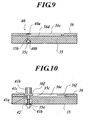
- the drum body has an insertion hole 35b to which the axis of a male screw 40a is inserted and a counterbore 35c receiving a nut 40b.
- the regulation plate 36 has a circular arc-like insertion hole 36d that receives the axis of the male screw 40a and that allows the regulation plate 36 to rotate to the drum body; and a circular arc-like counterbore 36c that receives the head and washer of the male screw 40a and that allows the regulation plate 36 to rotate to the drum body.
- the drum body includes an insertion hole 35c in which an axis 41a of a knob part 41 is inserted; and a counterbore 35e receiving a coil spring 42 for biasing downward a nut 41b screwed with a lower end of the axis 41a of the knob part 41.
- the regulation plate 36 has a circular arc-like insertion hole 36e that is inserted with the axis 41a of the knob part 41; and that allows the regulation plate 36 to rotate to the drum body and counterbores 36f that are provided at both ends of the circular arc-like insertion hole 36e and that receive a guard 41c of the knob part 41.
- the merchandise retention hole 35a of the drum 35 matches the hole 36a of the regulation plate 36, thereby allowing a merchandise having the maximum diameter to pass therethrough.
- the merchandise retention hole 35a of the drum 35 is partially superposed on the hole 36a of the regulation plate 36, thereby allowing only a small merchandise to pass therethrough.
- the knob part 41 In order to move the position of the knob part 41 from one of the counterbores 36f to the other of the counterbores 36f, the knob part 41 is raised against the biasing force of the coil spring 42 and the guard 41c is once disengaged from the counterbore 36f. In this status, the regulation plate 36 is rotated relative to the drum body in one direction so that the knob part 41 is moved along the insertion hole 36e to insert the guard 41c to the other counterbore 36f.
- the adapter 37 can be attached to or detached from the drum 35. As shown in Fig. 7 , the adapter 37 is structured so that merchandise retention holes 37a are provided in the periphery direction with an identical interval and in the same quantity as that of the merchandise retention holes 35a.
- the merchandise retention holes 37a have a smaller diameter than that of the merchandise retention holes 35a and are shaped so that the outer periphery is partially cut out.
- This adapter 37 can be attached to the drum 35 by bundling, while causing the merchandise retention hole 35a of the drum 35 to match the hole 36a of the regulation plate 36, the springs 36g at the upper part of the drum 35 to insert the bundled springs 36g into the hole 37c at the center of the adapter 37 from the lower side and by externally engaging the hole 37c with the rib 36b, thereby allowing circular cylindrical sections 37b at the lower face of the adapter 37 to be received by the merchandise retention holes 35a. Then, as shown in Fig. 8 , the article retention holes 37a of the adapter 37 and the edges thereof are engaged with the article retention holes 35a.
- This adapter 37 can be applied to a merchandise having a further smaller diameter than in the case where the regulation plate 36 is used.
- the upper edge of the concave part 27 has a notch 31.
- This notch 31 has a locking piece 32 provided in a projectable manner.
- a guide piece 33 is provided that regulates the upward displacement of the locking piece 32.
- This locking piece 32 is protruded to the upper face of the drum 35 while the drum 35 being placed on the concave part 27 to restrict the drum 35 in the concave part 27 as shown in Fig. 8 .
- the restriction of the drum 35 is cancelled, thereby detaching the drum 35 from the concave part 27.
- the box body 6 has therein the guide plate 47.
- the guide plate 47 is formed to have a bent shape.
- the lower end of this guide plate 47 is attached via the coil spring 49 to the partition plate 25.
- a raised part of the upper end of the guide plate 47 on the other hand has a concave part 47a that has an opening to the inner side.
- This concave part 47a is engaged with a protrusion 48 provided at the inner face of both walls at the sides of the merchandise filling opening 6a.
- the guide plate 47 is retained while being inclined from the intermediate part of the merchandise filling opening 6a to the partition plate 25.
- the guide plate 47 can be inclined to the front side to expand the merchandise filling opening 6a.
- merchandises can be filled and the interior of the box body 6 can be subjected to a maintenance operation in an easier manner.
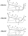
- Figs. 11A-11C illustrates the inner structure of the merchandise discharge opening 5.
- the front panel 8 of the box body 6 has a cover 5a for opening or closing the merchandise discharge opening 5.
- This cover 5a is attached to the front panel 8 so as to be rotatable around the axis 5b.
- the cover 5a is structured so that the cover 5a is rotated to the inner side of the box body 6.
- a discharge mechanism for the capsule merchandise A is provided at the inner side of the cover 5a in the box body 6.
- This discharge mechanism includes a stopper 5f provided at a bottom wall 6d and a shooter 5c provided at the upper side of the stopper 5f.
- the shooter 5c is attached to the box body 6 so as to be rotatable around the axis 5d.
- This shooter 5c has a substantially L-like bottom wall 5e.
- the shooter 5c receives the capsule merchandise A dropped from the merchandise discharge hole 28 provided at the concave part 27 of the partition plate 25 at the lower side and guides
- a depth dimension from the cover 5a to the stopper 5b is determined so that two capsule merchandises A can be housed in the article discharge opening 5. Furthermore, the merchandise discharge opening 5 has a width that is determined so that one capsule merchandise A can be housed therein.
- the cover 5a is rotated to the inner side after two capsule merchandises A is accumulated in the merchandise discharge opening 5, the front capsule merchandise A is scooped by the cover 5a as shown in Fig. 11(B) . Then, as shown in Fig.
- the tip end of the side wall of the shooter 5c comes to be abutted with the cover 5a in the middle of scooping the capsule merchandise A so that the tip end and the cover 5a cooperatively scoop the capsule merchandise A, thereby completely releasing the merchandise discharge opening 5.
- the capsule merchandise A existing on the bottom wall 6d is taken out.
- the cover 5a is once closed, the previously-scooped capsule merchandise A drops from the cover 5a.
- the capsule merchandise A can be taken out by reopening the cover 5a.
- This merchandise discharge mechanism can allow, even when the status as shown in Fig. 11(A) (i.e., when a plurality of capsule merchandises A exist) is caused, the cover 5a to be securely opened, thus allowing the merchandises to be securely taken out.
- the same function provided by the inwardly-curved cover 5a also can be provided by another structure in which the inner face of the cover 5a has a rib (e.g., a protrusion such as a protruded piece) and the inner face of the rib is curved or the rib includes a hook.
- a rib e.g., a protrusion such as a protruded piece
- the bottom of the box body 6 has a coin collection box 21.
- the coin collection box 21 can be detached from the box body 6 by being pulled to the front side.
- This coin collection box 21 can be fixed to the box body 6 by the lock 21a.
- This coin collection box 21 can be attached to or detached from the box body 6 while the control panel 8a having a slight distance from the bottom of the box body 6 or while the control panel 8a being completely detached from the box body 6.
- Fig. 1 illustrates the top panel 10 attached to the box body 6.
- Fig. 2 illustrates the top panel 10 detached from the box body 6. It is noted that Fig. 2 shows the top panel 10 in a reversed manner.
- the lower face of this top panel 10 has a tongue piece (insertion section) 53 extending in a lower direction.
- the tip end of the tongue piece has a hole (locking hole) 54.
- the upper wall 6b with which the top panel 10 is attached on the other hand has a rectangular hole (insertion hole) 52 for example.
- the locking member 58 is attached with the upper wall 6b of the box body 6. This locking member 58 can be inserted to or detached from the hole 54 of the tongue piece 53 inserted to the hole 52. Specifically, as shown in Fig. 12 , the locking member 58 has a shank 58a and an operation part 58b. This locking member 58 is attached to the box body 6 so as to be able to reciprocate in orthogonal direction relative to the insertion direction of the tongue piece 53 of the top panel 10. In this case, the operation direction matches the axial direction of the shank 53b. Furthermore, the locking member 58 can be rotated around the axis line of the shank 58a while the shank 58a being inserted to the hole 54.
- the locking member 58 When the locking member 58 is rotated in one direction while the shank 58a being inserted to the hole 54, the operation part 58a is locked to the lock part 58c to prevent the locking member 58 from being moved in the axis line direction. Thus, the locking member 58 is locked.
- the structure for attaching the top panel 10 as described above provides the following advantages. Specifically, although this embodiment has two boxes 2 stacked in the longitudinal direction, the lower face of the upper box 2 can have the same tongue piece 53 as that as in the top panel 10 to easily stack the boxes 2 as in the attachment of the top panel 10. Alternatively, by providing the tongue piece 53 as in the top panel 10 not only at the box 2 but also at the lower face of the display box, a display box (display case) can be easily provided as in the attachment of the top panel 10.
- the box 2 of the vending machine 1 includes the control panel 8a or the display section 17 for example and thus the interior is difficultly visually recognized. However, the use of the display box can display merchandises therein and thus a purchaser can know the merchandises stored in the vending machine 1.
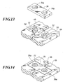
- the vending machine 1 includes a connection block 56 as shown in Fig. 2 , Fig. 13, and Fig. 14 .
- the connection block 56 has two holes (engagement sections) 56a. When two vending machines 1 are aligned and are connected to each other, the holes 56a of the connection blocks 56 are respectively engaged with the notches 50 of the box bodies 6 and are engaged with bosses (engagement sections) 51 of the box body 6 and are subsequently attached with the top panels 10.
- the block 55 having one hole 55a can be engaged with the boss 51 of the box body 6 to cover the notch 10a of the end plate 10.
- the blocks 55 and 56 are stored by engaging the holes 55a and 56a with the bosses 10b disposed upright in the back face of the top panel 10 or with the ribs 10C disposed upright in the back face of the top panel 10.
- the stands thereof are also preferably connected.
- the stands are connected by a clip that can simultaneously sandwich the side walls of the stands for example.
- the vending machine 1 includes: a discharge merchandise detection section 70 for detecting a discharged merchandise to output the detection signal; a coin detecting section 71 for detecting whether inserted coins are full or not to output the detection signal; a display section 74 for displaying the total number of discharged merchandises and some other content; a processing apparatus 73 for controlling the coin insertion preventing section 72 based on the detection signals outputted from the discharge merchandise detection section 70 and the coin detecting section 71 and for calculating, based on the detection signal outputted from the discharge merchandise detection section 70, the total number of the discharged merchandises to cause the display section 74 to display the number, and a reset section 75.
- the discharge merchandise detection section 70 is composed of a photosensor and so forth.
- the discharge merchandise detection section 70 is provided at the bottom part of the concave part 27 as described above.
- the discharge merchandise detection section 70 is currently positioned so as not to match the merchandise discharge hole 28 but the position thereof matches the position just below the merchandise retention hole 35a that matches the merchandise discharge hole 28 when the drum 35 is rotated in accordance with the subsequent rotation of the handle 4.
- the merchandise retention hole 35a at this position will be described as the next merchandise retention hole 35a.
- the processing apparatus 73 can calculate the total number of discharged merchandises by detecting whether the merchandise is retained at the next merchandise retention hole 35a or not whenever the handle 4 is rotated. When the next merchandise retention hole 35a does not retain a merchandise, this means that no merchandise is discharged when the drum 35 is rotated in accordance with the next rotation of the handle 4. Thus, in order to prevent a discharge failure of a merchandise, the processing apparatus 73 controls the coin insertion preventing section 72 to prevent the insertion of a coin.
- an additional discharge merchandise detection section is provided to detect a merchandise that passes through the merchandise discharge hole 28 and that is actually discharged or to detect the rotation of the drum 35 to calculate the number of discharged merchandises based on this detection signal.
- a pocket having a cover is provided in order to attach a discharge merchandise detection section that is abutted with the circumference face of the drum 35 by a spring and that has a protrusion slid while being abutted with the circumference face of the drum 35 in accordance with the rotation of the drum 35.
- the display section 74 is composed of a liquid crystal display section for example.
- the display section 74 is structured so that, when a Radio Frequency Identification (RFID) 77 is moved close to a predetermined position of the control panel 8a, a reader 78 reads the ID of the RFID 77.
- RFID Radio Frequency Identification
- the processing apparatus 73 causes the display section 74 to display the total number of discharged merchandises for a predetermined time (e.g., 30 seconds).
- a rotation detection section for detecting the rotation of the handle 4 also can be additionally provided so as to display, a predetermined video or today's fortune or example when the handle 4 is rotated.
- "SOLDOUT" When the next merchandise is not available, "SOLDOUT" also can be displayed.
- a switch also may provided in the merchandise discharge opening 5 so that the switch is turned ON when the switch is abutted with the cover 4a when the cover 4a is rotated to the inner side for a more-then-required distance (i.e., than a distance required for taking a merchandise out of the vending machine).
- the reset section 75 is provided at the back side of the control panel 8a so as not to be operable at the outer side of the box body 6.
- this reset section 75 is operated, the total number of discharged merchandises that has been counted and memorized by the storage section of the processing apparatus 73 is reset. Then, the processing apparatus 73 counts the total number of discharged merchandises from the point at which the reset section 75 is operated.
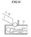
- the coin detecting section 71 is composed of a photosensor and so forth. As shown in Fig. 16 , the coin detecting section 71 is provided in a coin guide route, which is provided at the control panel 8a, for guiding a coin into the coin collection box 21. The coin detecting section 71 detects whether coins are retained in the coin guide route or not. When coins are retained in the coin guide route, this coin detecting section 71 outputs to the processing apparatus 73 a signal showing full of coins. Upon receiving the signal, the processing apparatus 73 controls the coin insertion preventing section 72 to prevent the insertion of coins.
- the coin insertion preventing section 72 is structured to include: a motor 80; a gear mechanism 81 operated by the motor 80; and a projection 83a that is operated by the gear mechanism 81 to block a coin route 82.
- the gear mechanism 81 is composed of gears 81a to 81j and rack teeth 81k.
- a motor power is transmitted, through the gears 81a to 81j and the rack teeth 81k, to a rack member 83 and the projection 83a provided in the rack member 83 protrudes in the coin route 82 to block the coin route 82, thereby preventing the insertion of coins.
- the motor 80 When the reset section 75 is operated, the motor 80 is rotated in an inverse direction and the projection 83a is retracted from the coin route 82, thereby allowing the insertion of a coin again.
- the reference numeral 84 in Fig. 17A represents a clutch and the gear 81i is pushed to the gear 81h by a biasing force by the coil spring 85 to cause the gear 81i and the gear 81h to be rotated in an integrated manner.
- the gear 81i When an excessive load is applied to the gear 81i, the gear 81i is moved away from the gear 81h against the biasing force by the coil spring 85, thereby cancelling the connection between the projection 83a-side components and the motor 80-side components.
- another structure also may be used by which merchandises can be controlled by storing merchandise data (e.g., the total number of discharged merchandises) in an RFID semiconductor memory provided in the box 2 so that an external reader can be used to read the merchandise data (e.g., the total number of discharged merchandises) stored in the semiconductor memory.
- the discharge merchandise detection section also can be used to detect discharged merchandises and the total number of discharged merchandises calculated based on the detection signals from the discharge merchandise detection section can be stored in the semiconductor memory.
- another structure instead of causing the calculation result by the processing apparatus to be stored in the semiconductor memory, another structure also may be used in which another counting unit is provided.
- Merchandise data also may be the one regarding the time at which a merchandise is sold.
- an attachment box 47b is provided at the back side of the raised part of the upper end of the guide plate 47 as shown in Fig. 4 so that this RFID can be attached at a later stage.
- the invention of the present application can be preferably used for a vending machine that requires a maintenance operation of a coin sorting unit for example.
Landscapes
- Physics & Mathematics (AREA)
- General Physics & Mathematics (AREA)
- Control Of Vending Devices And Auxiliary Devices For Vending Devices (AREA)
- Vending Machines For Individual Products (AREA)
Description
- The present invention relates to a vending machine. In particular, the present invention relates to a structure for providing a control panel.
- A merchandise discharge apparatus is known from
JP-A-2003-123135 Fig 3 ). - In the vending machine of
JP-A-2003 123135 - In view of the above problem, the present invention has been made. It is an objective of the present invention an to provide a vending machine that provides an easy maintenance operation of a coin sorting unit or the like.
-
US2001010315 describes an article discharging device having a main body with an opening which is provided in a front side, comprising a container for containing and holding an article. The container comprises a front wall at least a portion of which is transparent and an article entrance formed in an upper side. The container is able to close the opening and the article held in the container can be viewed through the transparent portion of the front wall in a closed state. The container can be rotated reciprocally around a predetermined axis, to take the closed state or an article entrance exposed state. -
US3804294 describes a dispensing machine which comprises a housing which is provided with a cover and which contains a removable cash box. A merchandise storage member is supported by the housing and is arranged to latch the cover closed. Locking structure locks the lid in place and also prevents removal of the storage member. Unlocking the locking structure enables removal of the lid to gain access to the storage member and/or enables the storage member to be shifted to unlatcht the cover and thereby gain access to the cash box. - According to a vending machine of a first invention, a vending machine in which a coin is inserted to cause an operation power is given to a handle to operate a discharge merchandise retention member to discharge a merchandise, includes: a box body comprising a front panel having a notch and a control panel including the handle and a coin sorting unit, wherein the control panel has the same shape as the notch and is attached to the box body in a detachable manner so as to be placed in the notch whilst the control panel is attached to box body.
- Preferably, a coin collection box is provided inside the box body and the coin collection box is externally covered by covering a front face of the coin collection box with the control panel while the control panel is attached to the box body so as to be placed in the notch.
- Preferably, a side face of the front panel has one of a convex groove or a concave groove, a side face of the control panel has the other of a convex groove or a concave groove, and the control panel is attached to the box body by sliding a side face of the control panel with a side face of the front panel from the upper side of the notch to engage the convex grove with the concave groove.
- Preferably, a merchandise filling opening is provided to the upper side of the notch of the box body, a cover is attached with the merchandise filling opening in a detachable manner, the control panel is prevented from moving upward when the cover is attached, and the control panel is allowed to move upward when the cover is detached.
- Preferably, one of the control panel and the box body has a spring, the spring allows descent of the control panel to stop at least at a position where the front face of the coin collection box remains exposed, and the control panel and the box body have a locking section that clamps the control panel in a completely depressed state against a biasing force of the spring.
- According to the invention, the control panel including the coin sorting unit can be detached from the box, thus realizing an easy maintenance.
- According to the first preferred embodiment, the coin collection box completely covered with the control panel provides secure safety and eliminates the need for a lock for a coin collection box, thus providing a proportional cost reduction.
- According to the second preferred embodiment, the control panel that can be slid to be attached to the box body can provide an easy attachment and can allow the control panel to be attached to the box body in a robust manner
- According to the third preferred embodiment, the cover blocks the upward movement of the control panel and thus eliminates a need for a special unit for locking the control panel, thus providing a proportional cost reduction
- According to the fourth preferred embodiment, the control panel is stopped halfway without being dropped to the lower end of the notch. Thus, a finger is prevented from being caught by the lower end of the control panel for example. Furthermore, the coin collection box can be taken out easily without being obstructed by the control panel.
-
- [
FIG. 1 ] This is a perspective view illustrating two vending machines according to the present invention stacked on each other. - [
FIG. 2 ] This is an exploded perspective view illustrating a vending machine according to the present invention. - [
FIG. 3 ] This is a perspective view illustrating a retainer plate attached to a cover so that the retainer plate is opened. - [
FIG. 4 ] This is a conceptual cross sectional view of a vending machine. - [
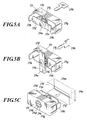
FIG. 5A ] This is a perspective view illustrating a lock body and a key for locking the cover to the box body. - [
FIG. 5B ] This is a perspective view illustrating the lock body and the key while the cover being locked to the box body. - [
FIG. 5C ] This is a perspective view illustrating a structure for attaching the lock body to the box body. - [
FIG. 6 ] This is a perspective view illustrating a buffering section for preventing the control panel from being dropped. - [
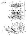
FIG. 7 ] This is an exploded perspective view illustrating a partition plate and a discharge merchandise retention member. - [
FIG. 8 ] This is a perspective view illustrating how a drum attached with an adapter is placed. - [
FIG. 9 ] This is a view illustrating a structure in which a drum body is attached with a regulation plate. - [
FIG. 10 ] This is a view illustrating an adjustment mechanism of a merchandise retention hole. - [
FIG. 11A ] This is a view illustrating the normal status of a cover for opening or closing the merchandise discharge opening. - [
FIG. 11B ] This is a view illustrating the cover for opening or closing the merchandise discharge opening being slightly pushed in. - [
FIG. 11C ] This is a view illustrating the cover for opening or closing the merchandise discharge opening being pushed in. - [
FIG. 12 ] This is a view illustrating a structure for attaching a top panel. - [
FIG. 13 ] This is an exploded perspective view illustrating a case where box bodies are connected while the box bodies being arranged to be adjacent to each other. - [
FIG. 14 ] This is a perspective view illustrating box bodies connected while the box bodies being arranged to be adjacent to each other. - [
FIG. 15 ] This is a block diagram illustrating the structure of an internal circuit. - [
FIG. 16 ] This is a view illustrating an example of a position at which a coin detecting section is attached. - [
FIG. 17A ] This is a top view illustrating the structure of a coin insertion preventing section. - [
FIG. 17B ] This is a back view illustrating the structure of the coin insertion preventing section. - In a
vending machine 1 ofFig. 1 , a merchandise A filled in a capsule (hereinafter referred to as capsule merchandise A) for example is stored in abox 2. When a person inserts a predetermined coin to a coin insertion slot 3 on a front face of thebox 2 and then subsequently rotates a handle 4, the capsule merchandise A in thebox 2 is discharged from adischarge opening 5 provided at the front face of thebox 2. In thevending machine 1 shown inFig. 1 , twoboxes 2 are stacked on each other and the bottom of thelower box 2 is attached to a stand including wheels and theupper box 2 has thereon atop panel 10. - As shown in
Fig. 2 , thebox 2 includes: abox body 6; acover 7 for covering amerchandise filling opening 6a of a front face of thebox body 6; acontrol panel 8a that comprises a part of afront panel 8 provided at the lower part of the front face of thebox body 6 and that includes acoin sorting unit 9 at the back face; and atop panel 10 covering the upper face of thebox body 6. - The
cover 7 is made of transparent resin and is formed, as shown inFig. 3 , to have a concave curved shape to the front side. The periphery part of thecover 7 has awall 11 protruding to the rear side. At the center in a width direction of theupper end wall 11a of thecover 7, along hole 12 is provided in a width direction of thebox 2.Cover 7 includesend walls 11a andside walls 11b. The upper end wall l1a of thecover 7 includessmall holes 13 formed to sandwich thelong hole 12. The inner face of thecover 7 has aretainer plate 15 that is also formed to have a curved shape as in thecover 7. Theretainer plate 15 is attached to a base section of the cover 7 (lower end of curved section) in a rotatable manner. The upper end edge of theretainer plate 15 has apin 16 protruding to the upper side. At the center immediately below the upper end edge of theretainer plate 15, apull 15a protruding to the rear side is provided. Theretainer plate 15 and thecover 7 have therebetween a display section 17 (e.g., pop) and thepin 16 is engaged with thesmall holes 13 of thecover 7 so as to be locked along thecover 7. When thedisplay section 17 is detached, one hand can grab thecover 7 and the other hand can pull thepull 15a to separate a free end of theretainer plate 15 from thecover 7, thereby detaching thedisplay section 17. It is noted that the lower end of the curved section of thecover 7 has a bendingpart 14 extending to the lower side. The lower edge of the bendingpart 14 hasprotrusions 14a at the left and right sides. - Next, a structure for attaching the
cover 7 will be described. Both side walls sandwiching themerchandise filling opening 6a of thebox body 6 are provided by a transparent plate so that the capsule merchandise A in the vending machine can be visually recognized from the lateral side of outside in an oblique direction. The inner faces of the both side walls of thebox body 6 have, as show inFig. 4 , a V-likeconcave part 18a having an opening to the upper side. Thisconcave part 18a is used for the positioning of thecover 7. Specifically, thecover 7 can be appropriately positioned by inserting, while thecover 7 being lowered to the front side of the front face (while the inner face of thecover 7 facing upward), the bending part of thecover 7 into theconcave part 18a to cause the front side part of the bending part to be abutted with the front-side wall of theconcave part 18a. In this status, when thecover 7 is raised around the lower edge of the bending part of thecover 7, the rear part of the bending part of thecover 7 is abutted with the wall at the rear side of theconcave part 18a. This position is a position at which thecover 7 is closed. The upper face of thecontrol panel 8a includes a long groove 18b extending in the width direction. This long groove 18b is a part that receives the bending part of thecover 7 and that is shaped so that thecover 7 can be raised or lowered. The upper face of thecontrol panel 8a includes alocking piece 18c provided at the center in the width direction. The upper face of thecontrol panel 8a includes thelocking piece 18c. Thislocking piece 18c prevents an upward movement of theclosed cover 7. Specifically, when thecover 7 is raised, the lower end of the curved section is inserted to the lower side of thelocking piece 18c to prevent the upward movement of theclosed cover 7. In order to effectively prevent the upward movement of the thiscover 7, the lower end of the curved section of thecover 7 preferably has a curvature different from those of the other parts of the curved section so that the lower end of the bending part of thecover 7 is appropriately locked by thelocking piece 18c. - It is noted that, when the
cover 7 is closed, theprotrusion 14a formed at the bending part of thecover 7 is inserted to the lower side of the upper wall of thecontrol panel 8a. As a result, thecover 7 is locked to thecontrol panel 8a. Furthermore, thecover 7 also preferably has a handle at the front face so that thecover 7 can be detached from thebox body 6 by being pulled down easily with the handle. - As shown in
Fig. 2 , thebox body 6 is structured so that themerchandise filling opening 6a has thereon alock 19. As shown inFig. 5 , thelock 19 is composed of alock body 19a and a key 19b. Among them, thelock body 19a is composed of acylinder section 19c, arotor part 19d, and lockingpieces lock body 19a is retained by anattachment block 19g in a detachable manner. It is noted that, although thelocking piece 19e and thelocking piece 19f are integrated in this embodiment, the structure is not particularly limited. - Next, a method to attach the
lock body 19a to theattachment block 19g will be described. When thelock body 19a is attached to theattachment block 19g, the lockingpieces lock body 19a in advance. Then, thelock body 19a in this status is pushed into theconcave part 19h in front of theattachment block 19g. Then, a lock part (not shown) at the outer periphery of thecylinder section 19c is abutted to the bottom part of theconcave part 19b, thus preventing thelock body 19a from being pushed further. The bottom of theconcave part 19h on the other hand includes a penetration hole having an opening to the rear side of theattachment block 19g. Thus, when thelock body 19a is in this state, a part of thecylinder section 19c protrudes from the rear side of theattachment block 19a. This protruded section includes amale screw section 19i that is screwed with anut 19j. Finally, the lockingpieces rotor part 19d from the rear side of the protruded section. - As described above, the
lock body 19a is attached to theattachment block 19g. It is noted that thelock body 19a can be detached from theattachment block 19g in an opposite order of that of the above operation. - Next, a structure for attaching the
attachment block 19g will be described. Theattachment block 19g is provided withnail pieces box body 6 on the other hand has aconcave part 191 that can be engaged with theattachment block 19g. The bottom part of theconcave part 191 includesholes - In order to attach the
attachment block 19g attached with thelock body 19a to thebox body 6, the lockingpieces Fig. 5(A) . Next, as shown inFig. 5(C) , theattachment block 19g is engaged into theconcave part 191 by inserting the lockingpieces pieces nail pieces 19k pass through thehole 19m. A tip end of theother nail piece 19k on the other hand passes through thehole 19n. Then, protrusions provided at the outer side of thenail pieces concave part 191 by the elasticity of thenail pieces - In the manner as described above, the
attachment block 19g is attached to thebox body 6. It is noted that theattachment block 19g can be detached from thebox body 6 by using a hand to push out theattachment block 19g from the inner side of thebox body 6 while the lockingpieces - Next, a structure for locking the
cover 7 by thislock 19 will be described. While the lockingpieces lock body 19a being placed in the lateral direction, thecover 7 is not locked to thebox body 6. When the lockingpieces locking piece 19e is inserted to thelong hole 12 of thecover 7 and theother locking piece 19f is inserted to a long hole (not shown) of theupper wall 6b of thebox body 6. As a result, thecover 7 is locked to thebox body 6 and at the same time theattachment block 19g is fixed to thebox body 6. - It is noted that, although this embodiment has the
cover 7 locked to thebox body 6 by directly locking thecover 7 by thelocking piece 19e of thelock 19, another structure also may be employed in which thebox 2 has a movable member that enables a locking position and a lock cancellation position of thecover 7 so that thelock 19 can be used to lock the movable member to the locking position to indirectly lock thecover 7 to thebox body 6. Although this embodiment has locked thecover 7 to thebox body 6 by inserting thelocking piece 19f also into a long hole (not shown)of the upper wall of thebox body 6, another structure also may be used in which thelocking piece 19e is merely inserted to thelong hole 12 of thecover 7. Alternatively, another structure also may be used in which, in order to insert thelocking piece 19f also to a long hole (not shown) of theupper wall 6b of thebox body 6, twoupper walls 6b are provided at the upper and lower sides so that thelocking piece 19f can be inserted to the long hole of the lower upper wall or the lower side of theupper wall 6b also may have a locking member including a long hole. - As shown in
Fig. 2 , thecontrol panel 8a has an inverted L-like shape when seen from the front side. Thecontrol panel 8a is attached to thebox body 6 in a detachable manner. -
Fig. 2 shows thecontrol panel 8a detached from thebox body 6 and thefront panel 8 of thebox body 6 has a notch 20 having the same shape as that of thecontrol panel 8a. Wall faces at both sides of thecontrol panel 8a haveconcave grooves 23 arranged in the longitudinal direction with a predetermined interval. A wall face for separating the notch 20 in thebox body 6 on the other hand hasconvex grooves 22 arranged in the longitudinal direction with an appropriate interval to the inner side of the width direction. In order to attach thecontrol panel 8a to thebox body 6, while thecover 7 being detached from thebox body 6, thecontrol panel 8a being separated from the bottom of the notch 20 is engaged into the notch 20 from the front face side to slide thecontrol panel 8a in the lower direction to engage theconcave grooves 23 with theconvex grooves 22 to attach thecontrol panel 8a to a predetermined position of thebox body 6. Thecontrol panel 8a can be detached from thebox body 6 on the other hand in an opposite order of that of the above operation. It is noted that thecontrol panel 8a includes a connector (not shown) that can be connected to aconnector 6c at thebox body 6. These connectors are automatically connected when thecontrol panel 8a is attached to thebox body 6 to electrically connect the side of thecontrol panel 8a to the side of thebox body 6. - As described above, the
control panel 8a is formed separately from thebox body 6 and thecontrol panel 8a is structured so as to be detachable from thebox body 6. This provides not only an easy maintenance of thecontrol panel 8a and but also an easy maintenance of the interior of thebox body 6. - It is noted that, as shown in
Fig. 2 andFig. 6 , wall faces at the left and right sides of thecontrol panel 8a have lockingpieces 8b for retaining thecontrol panel 8 while thecontrol panel 8 having a slight distance from the bottom of the notch 20. Thislocking piece 8b is abutted with aprotrusion 8d that is provided at one wall face which forms a part of the notch 20 and is biased by aspring 8c while thecontrol panel 8a being retained to have a slight distance from the bottom of the notch 20. However, the retaining force by thislocking piece 8b is not so high. Specifically, the biasing force of thespring 8c toward this locking piece is sufficient to support the weight of thecontrol panel 8a. However, when thecontrol panel 8a is manually depressed in the lower direction, thecontrol panel 8a is moved downward against the biasing force. The structure as described above is provided for the purpose of preventing thecontrol panel 8a from jumping down when thecontrol panel 8a is engaged into thebox body 6 and for the purpose of allowing a coin collection box 21 (which will be described later) to be drawn while thecontrol panel 8a being positioned to have a slight distance from the bottom of the notch 20. - Next, a structure for fixing the
control panel 8a will be described. As shown inFig. 2 ,Fig. 4 ,Fig. 7 , andFig. 8 , thecontrol panel 8a and a partition plate 25 (which will be described later) respectively have alocking section 57 for locking thecontrol panel 8a to thebox body 6. The twosections 57 have the same structure and thus thelocking section 57 provided at thepartition plate 25 will be exemplarily described. As shown inFig. 7 , the lockingsection 57 includes alocking pin 57b that operates by the operation of theoperation part 57a. When thecontrol panel 8a is attached to thebox body 6 and theoperation part 57a of thelocking section 57 is operated to protrude thelocking pin 57b, the lockingpin 57b is positioned at the upper side of thecontrol panel 8a. Thislocking section 57 prevents the upward movement of thecontrol panel 8a. The lockingsection 57 provided at thecontrol panel 8a on the other hand causes thelocking pin 57b protruded by the operation of theoperation part 57a to be engaged with a concave part (not shown) provided in thebox body 6. - It is noted that the
locking section 57 is not always required to be provided. The reason is that, by attaching thecontrol panel 8a and subsequently attaching thecover 7 to fix thecover 7 to thebox body 6 by rotating the key 19b, the upward movement of thecontrol panel 8a is regulated by thecover 7 to prevent thecontrol panel 8a from being detached. However, the existence of thelocking section 57 can allow thecontrol panel 8a to be more firmly fixed to thebox body 6. - As shown in
Fig. 4 , thebox body 6 includes therein thepartition plate 25 for partitioning thebox body 6 to upper and lower parts. The upper part of thispartition plate 25 functions as amerchandise storage space 26. Thepartition plate 25 has a circularconcave part 27 as shown inFig. 4 andFig. 7 . The bottom part of theconcave part 27 has onemerchandise discharge hole 28. A dischargedarticle retention member 34 is placed in theconcave part 27. The bottom part of theconcave part 27 also has a next merchandise detection section 70 (which will be described later). The bottom part of theconcave part 27 also has arectangular hole 43 for exposing agear 44. - As shown in
Fig. 7 , the dischargemerchandise retention member 34 is composed of adrum 35 and anadapter 37. It is noted that thedrum 35 may not always have aregulation plate 36. - The
drum 35 has a plurality ofmerchandise retention holes 35a (fourmerchandise retention holes 35a in this embodiment) that retain a merchandise having a relatively large diameter (e.g., a merchandise filled in a capsule) and that are provided in the circumference direction with an identical interval. Furthermore, thedrum 35 includesrack teeth 38 at the circumference edge of the lower face. Thus, when thedrum 35 is placed on theconcave part 27, therack teeth 38 are meshed with thegear 44. As shown inFig. 4 , thegear 44 is connected to the handle 4 via anaxis 45, thegears axis 4a. Thus, when the handle 4 is rotated, the rotation power of the handle 4 is transmitted to thedrum 35 via theaxis 4a, thegears axis 45, and thegear 44, and therack teeth 38, thereby rotating thedrum 35. In this case, one rotation of the handle 4 causes the rotation of thedrum 35 in an amount of 360 degrees/(the number of themerchandise retention holes 35a). Thus, whenever one rotation of the handle 4 is caused, themerchandise retention hole 35a matches themerchandise discharge hole 28 and thus merchandises retained at themerchandise retention hole 35a are discharged one by one. - The circumference face of the
drum 35 has aconcave part 39 having the same function as that of ratchet teeth. On the other hand, a part of the circumference wall forming theconcave part 27 has arectangular hole 29. Therectangular hole 29 has aratchet piece 30 that has the same function as that of a ratchet nail and that is provided in a retractable manner. Thisratchet piece 30 is biased in a protrusion direction by a spring (not shown) and theconcave part 39 of thedrum 35 is engaged with theratchet piece 30 so that theratchet piece 30 prevents the inverse rotation of thedrum 35. - The
drum 35 includes theregulation plate 36. Theregulation plate 36 is provided on the drum body. Theregulation plate 36 is structured to be rotatable around the axis center of thedrum 35 in a predetermined angle range. Thisregulation plate 36 hasholes 36a in the circumference direction that have the same shapes as those of themerchandise retention holes 35a and that are provided in the same number and pitch of themerchandise retention holes 35a. Thehole 36a of theregulation plate 36 functions to change, in accordance with the rotation amount of theregulation plate 36, the diameter of themerchandise retention hole 35a. Furthermore, arib 36b, for guiding the merchandise at the upper part to the outer side of the radius direction of thedrum 35, is disposed upright in the center of theregulation plate 36. Furthermore, in order to mix merchandises at the upper side of thedrum 35 therib 36a has foursprings 36g that are arranged to the outer side in an oblique upward direction. - Next, a structure for attaching the
regulation plate 36 will be described. As shown inFig. 7 andFig. 9 , thedrum 35 and theregulation plate 36 are mutually attached by ascrew 40. Specifically, the drum body has aninsertion hole 35b to which the axis of amale screw 40a is inserted and acounterbore 35c receiving anut 40b. On the other hand, theregulation plate 36 has a circular arc-like insertion hole 36d that receives the axis of themale screw 40a and that allows theregulation plate 36 to rotate to the drum body; and a circular arc-like counterbore 36c that receives the head and washer of themale screw 40a and that allows theregulation plate 36 to rotate to the drum body. - Next, a merchandise retention hole adjustment mechanism will be described. As shown in
Fig. 10 , the drum body includes aninsertion hole 35c in which anaxis 41a of aknob part 41 is inserted; and acounterbore 35e receiving acoil spring 42 for biasing downward anut 41b screwed with a lower end of theaxis 41a of theknob part 41. On the other hand, theregulation plate 36 has a circular arc-like insertion hole 36e that is inserted with theaxis 41a of theknob part 41; and that allows theregulation plate 36 to rotate to the drum body and counterbores 36f that are provided at both ends of the circular arc-like insertion hole 36e and that receive aguard 41c of theknob part 41. - Next, a method for adjusting the
merchandise retention hole 35a by theregulation plate 36 will be described. When theguard 41c of theknob part 41 is received by one of thecounterbores 36f, themerchandise retention hole 35a of thedrum 35 matches thehole 36a of theregulation plate 36, thereby allowing a merchandise having the maximum diameter to pass therethrough. When theguard 41c of theknob part 41 is received by the other of thecounterbores 36f on the other hand, themerchandise retention hole 35a of thedrum 35 is partially superposed on thehole 36a of theregulation plate 36, thereby allowing only a small merchandise to pass therethrough. - In order to move the position of the
knob part 41 from one of thecounterbores 36f to the other of thecounterbores 36f, theknob part 41 is raised against the biasing force of thecoil spring 42 and theguard 41c is once disengaged from thecounterbore 36f. In this status, theregulation plate 36 is rotated relative to the drum body in one direction so that theknob part 41 is moved along theinsertion hole 36e to insert theguard 41c to theother counterbore 36f. - The
adapter 37 can be attached to or detached from thedrum 35. As shown inFig. 7 , theadapter 37 is structured so thatmerchandise retention holes 37a are provided in the periphery direction with an identical interval and in the same quantity as that of themerchandise retention holes 35a. Themerchandise retention holes 37a have a smaller diameter than that of themerchandise retention holes 35a and are shaped so that the outer periphery is partially cut out. Thisadapter 37 can be attached to thedrum 35 by bundling, while causing themerchandise retention hole 35a of thedrum 35 to match thehole 36a of theregulation plate 36, thesprings 36g at the upper part of thedrum 35 to insert the bundledsprings 36g into thehole 37c at the center of theadapter 37 from the lower side and by externally engaging thehole 37c with therib 36b, thereby allowing circularcylindrical sections 37b at the lower face of theadapter 37 to be received by themerchandise retention holes 35a. Then, as shown inFig. 8 , thearticle retention holes 37a of theadapter 37 and the edges thereof are engaged with thearticle retention holes 35a. Thisadapter 37 can be applied to a merchandise having a further smaller diameter than in the case where theregulation plate 36 is used. - As shown in
Fig. 7 , the upper edge of theconcave part 27 has anotch 31. Thisnotch 31 has alocking piece 32 provided in a projectable manner. At the upper part of a moving range of the locking piece, aguide piece 33 is provided that regulates the upward displacement of the lockingpiece 32. This lockingpiece 32 is protruded to the upper face of thedrum 35 while thedrum 35 being placed on theconcave part 27 to restrict thedrum 35 in theconcave part 27 as shown inFig. 8 . On the other hand, when the lockingpiece 32 is retracted from the upper face of thedrum 35, the restriction of thedrum 35 is cancelled, thereby detaching thedrum 35 from theconcave part 27. - As shown in
Fig. 1 andFig. 4 , thebox body 6 has therein theguide plate 47. Theguide plate 47 is formed to have a bent shape. The lower end of thisguide plate 47 is attached via thecoil spring 49 to thepartition plate 25. A raised part of the upper end of theguide plate 47 on the other hand has aconcave part 47a that has an opening to the inner side. Thisconcave part 47a is engaged with aprotrusion 48 provided at the inner face of both walls at the sides of themerchandise filling opening 6a. When thisconcave part 47a is engaged with theprotrusion 48, theguide plate 47 is retained while being inclined from the intermediate part of themerchandise filling opening 6a to thepartition plate 25. When the engagement of theconcave part 47a and theprotrusion 48 is cancelled, theguide plate 47 can be inclined to the front side to expand themerchandise filling opening 6a. Thus, merchandises can be filled and the interior of thebox body 6 can be subjected to a maintenance operation in an easier manner. -
Figs. 11A-11C illustrates the inner structure of themerchandise discharge opening 5. Thefront panel 8 of thebox body 6 has acover 5a for opening or closing themerchandise discharge opening 5. Thiscover 5a is attached to thefront panel 8 so as to be rotatable around theaxis 5b. Thecover 5a is structured so that thecover 5a is rotated to the inner side of thebox body 6. At the inner side of thecover 5a in thebox body 6, a discharge mechanism for the capsule merchandise A is provided. This discharge mechanism includes astopper 5f provided at abottom wall 6d and ashooter 5c provided at the upper side of thestopper 5f. Among them, theshooter 5c is attached to thebox body 6 so as to be rotatable around theaxis 5d. Thisshooter 5c has a substantially L-like bottom wall 5e. Thus, theshooter 5c receives the capsule merchandise A dropped from themerchandise discharge hole 28 provided at theconcave part 27 of thepartition plate 25 at the lower side and guides it to themerchandise discharge opening 5. - As shown in
Fig. 11A , a depth dimension from thecover 5a to thestopper 5b is determined so that two capsule merchandises A can be housed in thearticle discharge opening 5. Furthermore, themerchandise discharge opening 5 has a width that is determined so that one capsule merchandise A can be housed therein. When thecover 5a is rotated to the inner side after two capsule merchandises A is accumulated in themerchandise discharge opening 5, the front capsule merchandise A is scooped by thecover 5a as shown inFig. 11(B) . Then, as shown inFig. 11(c) , the tip end of the side wall of theshooter 5c comes to be abutted with thecover 5a in the middle of scooping the capsule merchandise A so that the tip end and thecover 5a cooperatively scoop the capsule merchandise A, thereby completely releasing themerchandise discharge opening 5. Then, the capsule merchandise A existing on thebottom wall 6d is taken out. Next, when thecover 5a is once closed, the previously-scooped capsule merchandise A drops from thecover 5a. Thus, the capsule merchandise A can be taken out by reopening thecover 5a. This merchandise discharge mechanism can allow, even when the status as shown inFig. 11(A) (i.e., when a plurality of capsule merchandises A exist) is caused, thecover 5a to be securely opened, thus allowing the merchandises to be securely taken out. - It is noted that, although the above embodiment has provided the lower part of the
cover 5a curved to the inner side of the case body, the same function provided by the inwardly-curved cover 5a also can be provided by another structure in which the inner face of thecover 5a has a rib (e.g., a protrusion such as a protruded piece) and the inner face of the rib is curved or the rib includes a hook. - As shown in
Fig. 2 andFig. 4 , the bottom of thebox body 6 has acoin collection box 21. Thecoin collection box 21 can be detached from thebox body 6 by being pulled to the front side. Thiscoin collection box 21 can be fixed to thebox body 6 by thelock 21a. Thiscoin collection box 21 can be attached to or detached from thebox body 6 while thecontrol panel 8a having a slight distance from the bottom of thebox body 6 or while thecontrol panel 8a being completely detached from thebox body 6. - It is noted that, when the
control panel 8a is attached, thecoin collection box 21 attached to thebox body 6 is completely covered and cannot be visually recognized from the front side. -
Fig. 1 illustrates thetop panel 10 attached to thebox body 6.Fig. 2 illustrates thetop panel 10 detached from thebox body 6. It is noted thatFig. 2 shows thetop panel 10 in a reversed manner. The lower face of thistop panel 10 has a tongue piece (insertion section) 53 extending in a lower direction. The tip end of the tongue piece has a hole (locking hole) 54. Theupper wall 6b with which thetop panel 10 is attached on the other hand has a rectangular hole (insertion hole) 52 for example. By inserting thetongue piece 53 of thetop panel 10 to thehole 52 of theupper wall 6b, thetop panel 10 is placed on thebox body 6. - Furthermore, the locking
member 58 is attached with theupper wall 6b of thebox body 6. This lockingmember 58 can be inserted to or detached from thehole 54 of thetongue piece 53 inserted to thehole 52. Specifically, as shown inFig. 12 , the lockingmember 58 has ashank 58a and anoperation part 58b. This lockingmember 58 is attached to thebox body 6 so as to be able to reciprocate in orthogonal direction relative to the insertion direction of thetongue piece 53 of thetop panel 10. In this case, the operation direction matches the axial direction of the shank 53b. Furthermore, the lockingmember 58 can be rotated around the axis line of theshank 58a while theshank 58a being inserted to thehole 54. When the lockingmember 58 is rotated in one direction while theshank 58a being inserted to thehole 54, theoperation part 58a is locked to thelock part 58c to prevent the lockingmember 58 from being moved in the axis line direction. Thus, the lockingmember 58 is locked. - The structure for attaching the
top panel 10 as described above provides the following advantages. Specifically, although this embodiment has twoboxes 2 stacked in the longitudinal direction, the lower face of theupper box 2 can have thesame tongue piece 53 as that as in thetop panel 10 to easily stack theboxes 2 as in the attachment of thetop panel 10. Alternatively, by providing thetongue piece 53 as in thetop panel 10 not only at thebox 2 but also at the lower face of the display box, a display box (display case) can be easily provided as in the attachment of thetop panel 10. Thebox 2 of thevending machine 1 includes thecontrol panel 8a or thedisplay section 17 for example and thus the interior is difficultly visually recognized. However, the use of the display box can display merchandises therein and thus a purchaser can know the merchandises stored in thevending machine 1. - (The
vending machine 1 includes aconnection block 56 as shown inFig. 2 ,Fig. 13, and Fig. 14 . Theconnection block 56 has two holes (engagement sections) 56a. When twovending machines 1 are aligned and are connected to each other, theholes 56a of the connection blocks 56 are respectively engaged with thenotches 50 of thebox bodies 6 and are engaged with bosses (engagement sections) 51 of thebox body 6 and are subsequently attached with thetop panels 10. - When one
vending machine 1 is used separately, theblock 55 having onehole 55a can be engaged with theboss 51 of thebox body 6 to cover thenotch 10a of theend plate 10. - When the
blocks blocks holes bosses 10b disposed upright in the back face of thetop panel 10 or with the ribs 10C disposed upright in the back face of thetop panel 10. - It is noted that, when neighboring
vending machines 1 are connected by theconnection block 56, the stands thereof are also preferably connected. In this case, the stands are connected by a clip that can simultaneously sandwich the side walls of the stands for example. - As shown in
Fig. 15 , thevending machine 1 includes: a dischargemerchandise detection section 70 for detecting a discharged merchandise to output the detection signal; acoin detecting section 71 for detecting whether inserted coins are full or not to output the detection signal; adisplay section 74 for displaying the total number of discharged merchandises and some other content; aprocessing apparatus 73 for controlling the coininsertion preventing section 72 based on the detection signals outputted from the dischargemerchandise detection section 70 and thecoin detecting section 71 and for calculating, based on the detection signal outputted from the dischargemerchandise detection section 70, the total number of the discharged merchandises to cause thedisplay section 74 to display the number, and areset section 75. - The discharge
merchandise detection section 70 is composed of a photosensor and so forth. The dischargemerchandise detection section 70 is provided at the bottom part of theconcave part 27 as described above. The dischargemerchandise detection section 70 is currently positioned so as not to match themerchandise discharge hole 28 but the position thereof matches the position just below themerchandise retention hole 35a that matches themerchandise discharge hole 28 when thedrum 35 is rotated in accordance with the subsequent rotation of the handle 4. Hereinafter, themerchandise retention hole 35a at this position will be described as the nextmerchandise retention hole 35a. By retaining a merchandise at the nextmerchandise retention hole 35a, the merchandise is securely discharged when thedrum 35 is rotated in accordance with the next rotation of the handle 4 and the nextmerchandise retention hole 35a matches themerchandise discharge hole 28. Thus, theprocessing apparatus 73 can calculate the total number of discharged merchandises by detecting whether the merchandise is retained at the nextmerchandise retention hole 35a or not whenever the handle 4 is rotated. When the nextmerchandise retention hole 35a does not retain a merchandise, this means that no merchandise is discharged when thedrum 35 is rotated in accordance with the next rotation of the handle 4. Thus, in order to prevent a discharge failure of a merchandise, theprocessing apparatus 73 controls the coininsertion preventing section 72 to prevent the insertion of a coin. - It is noted that another configuration also may be used in which, in addition to the discharge
merchandise detection section 70 for detecting the next discharge merchandise to prevent a discharge failure of a merchandise, an additional discharge merchandise detection section is provided to detect a merchandise that passes through themerchandise discharge hole 28 and that is actually discharged or to detect the rotation of thedrum 35 to calculate the number of discharged merchandises based on this detection signal. As shown inFig. 7 , in this embodiment, a pocket having a cover is provided in order to attach a discharge merchandise detection section that is abutted with the circumference face of thedrum 35 by a spring and that has a protrusion slid while being abutted with the circumference face of thedrum 35 in accordance with the rotation of thedrum 35. - The
display section 74 is composed of a liquid crystal display section for example. Thedisplay section 74 is structured so that, when a Radio Frequency Identification (RFID) 77 is moved close to a predetermined position of thecontrol panel 8a, areader 78 reads the ID of theRFID 77. When the ID matches thevending machine 1, theprocessing apparatus 73 causes thedisplay section 74 to display the total number of discharged merchandises for a predetermined time (e.g., 30 seconds). It is noted that thedisplay section 74 also can display content other than the total number of discharged merchandises. For example, a rotation detection section for detecting the rotation of the handle 4 also can be additionally provided so as to display, a predetermined video or today's fortune or example when the handle 4 is rotated. When the next merchandise is not available, "SOLDOUT" also can be displayed. When moving theRFID 77 closer to a predetermined position of thecontrol panel 8a to cause thedisplay section 74 to display the total number of discharged merchandises, in adding to this an activation of another switch may also be necessitated. For example, a switch also may provided in themerchandise discharge opening 5 so that the switch is turned ON when the switch is abutted with thecover 4a when thecover 4a is rotated to the inner side for a more-then-required distance (i.e., than a distance required for taking a merchandise out of the vending machine). - The
reset section 75 is provided at the back side of thecontrol panel 8a so as not to be operable at the outer side of thebox body 6. When thisreset section 75 is operated, the total number of discharged merchandises that has been counted and memorized by the storage section of theprocessing apparatus 73 is reset. Then, theprocessing apparatus 73 counts the total number of discharged merchandises from the point at which thereset section 75 is operated. - The
coin detecting section 71 is composed of a photosensor and so forth. As shown inFig. 16 , thecoin detecting section 71 is provided in a coin guide route, which is provided at thecontrol panel 8a, for guiding a coin into thecoin collection box 21. Thecoin detecting section 71 detects whether coins are retained in the coin guide route or not. When coins are retained in the coin guide route, thiscoin detecting section 71 outputs to the processing apparatus 73 a signal showing full of coins. Upon receiving the signal, theprocessing apparatus 73 controls the coininsertion preventing section 72 to prevent the insertion of coins. - As shown in
Figs. 17A and 17B , the coininsertion preventing section 72 is structured to include: amotor 80; agear mechanism 81 operated by themotor 80; and aprojection 83a that is operated by thegear mechanism 81 to block acoin route 82. Thegear mechanism 81 is composed ofgears 81a to 81j and rackteeth 81k. A motor power is transmitted, through thegears 81a to 81j and therack teeth 81k, to arack member 83 and theprojection 83a provided in therack member 83 protrudes in thecoin route 82 to block thecoin route 82, thereby preventing the insertion of coins. When thereset section 75 is operated, themotor 80 is rotated in an inverse direction and theprojection 83a is retracted from thecoin route 82, thereby allowing the insertion of a coin again. It is noted that the reference numeral 84 inFig. 17A represents a clutch and thegear 81i is pushed to thegear 81h by a biasing force by thecoil spring 85 to cause thegear 81i and thegear 81h to be rotated in an integrated manner. When an excessive load is applied to thegear 81i, thegear 81i is moved away from thegear 81h against the biasing force by thecoil spring 85, thereby cancelling the connection between theprojection 83a-side components and the motor 80-side components. - As described above, an embodiment of the present invention has been described. However, the present invention is not limited to this embodiment and also can be subjected to various modifications within the scope of the invention as defined in the claims.
- For example, another structure also may be used by which merchandises can be controlled by storing merchandise data (e.g., the total number of discharged merchandises) in an RFID semiconductor memory provided in the
box 2 so that an external reader can be used to read the merchandise data (e.g., the total number of discharged merchandises) stored in the semiconductor memory. For example, the discharge merchandise detection section also can be used to detect discharged merchandises and the total number of discharged merchandises calculated based on the detection signals from the discharge merchandise detection section can be stored in the semiconductor memory. In this case, instead of causing the calculation result by the processing apparatus to be stored in the semiconductor memory, another structure also may be used in which another counting unit is provided. Merchandise data also may be the one regarding the time at which a merchandise is sold. - In the above embodiment, an attachment box 47b is provided at the back side of the raised part of the upper end of the
guide plate 47 as shown inFig. 4 so that this RFID can be attached at a later stage. - The invention of the present application can be preferably used for a vending machine that requires a maintenance operation of a coin sorting unit for example.
Claims (5)
- A vending machine (1) in which a coin is inserted and an operation power is given to a handle (4) to operate a discharge merchandise retention member (34), so as to discharge a merchandise, characterised in that the vending machine (1) comprisesa box body (2) comprising a front panel (8) having a notch (20); anda control panel (8a) including the handle (4) and a coin sorting unit (9)wherein the control panel (8a) has the same shape as the notch (20) and is attached to the box body (2) in a detachable manner so as to be placed in the notch (20) whilst the control panel (8a) is attached to the box body (2).
- A vending machine (1) as claimed in claim 1,
wherein a coin collection box (21) is provided inside the box body (2) and the coin collection box (21) is externally covered by covering a front face of the coin collection box (21) with the control panel (8a) while the control panel (8a) is attached to the box body (2) so as to be placed in the notch (20). - A vending machine (1) as claimed in claim 1 or claim 2,
wherein a side face of the front panel (8) has one of a convex groove or a concave groove,
a side face of the control panel (8a) has the other of a convex groove or a concave groove, and
the control panel (8a) is attached to the box body (2) by sliding a side face of the control panel (8a) with a side face of the front panel (8) from the upper side of the notch (20) to engage the convex groove with the concave groove. - A vending machine (1) as claimed in claim 3,
wherein a merchandise filling opening (6a) is provided to the upper side of the notch (20) of the box body (2),
a cover (7) is attached with the merchandise filling opening (6a) in a detachable manner,
the control panel (8a) is prevented from moving upwardly when the cover (7) is attached, and
the control panel (8a) is allowed to move upwardly when the cover (7) is detached. - A vending machine (1) as claimed in claim 4,
wherein one of the control panel (8a) and the box body (2) has a spring (8c), the spring (8c) allows descent of the control panel (8a) to stop at least at a position where the front face of the coin collection box (21) remains exposed, and
the control panel (8a) and the box body (2) each have a locking section (57) that clamps the control panel (8a) in a completely depressed state against a biasing force of the spring (8c).
Applications Claiming Priority (2)
| Application Number | Priority Date | Filing Date | Title |
|---|---|---|---|
| JP2004369547A JP4814517B2 (en) | 2004-12-21 | 2004-12-21 | vending machine |
| PCT/JP2005/023487 WO2006068177A1 (en) | 2004-12-21 | 2005-12-21 | Automatic dispenser |
Publications (3)
| Publication Number | Publication Date |
|---|---|
| EP1837835A1 EP1837835A1 (en) | 2007-09-26 |
| EP1837835A4 EP1837835A4 (en) | 2008-03-19 |
| EP1837835B1 true EP1837835B1 (en) | 2010-08-18 |
Family
ID=36601775
Family Applications (1)
| Application Number | Title | Priority Date | Filing Date |
|---|---|---|---|
| EP05820133A Expired - Lifetime EP1837835B1 (en) | 2004-12-21 | 2005-12-21 | Automatic dispenser |
Country Status (11)
| Country | Link |
|---|---|
| US (1) | US7748513B2 (en) |
| EP (1) | EP1837835B1 (en) |
| JP (1) | JP4814517B2 (en) |
| KR (1) | KR101166055B1 (en) |
| CN (1) | CN101084531B (en) |
| AU (1) | AU2005320148A1 (en) |
| CA (1) | CA2590470C (en) |
| DE (1) | DE602005023062D1 (en) |
| ES (1) | ES2348547T3 (en) |
| TW (1) | TW200632794A (en) |
| WO (1) | WO2006068177A1 (en) |
Families Citing this family (4)
| Publication number | Priority date | Publication date | Assignee | Title |
|---|---|---|---|---|
| KR100825740B1 (en) | 2006-10-23 | 2008-04-29 | 한국전자통신연구원 | Automatic sales system using RFID and its method |
| JP4936576B1 (en) * | 2012-01-19 | 2012-05-23 | 株式会社バンダイ | Manual product sales equipment |
| CN107705437A (en) * | 2017-09-29 | 2018-02-16 | 苏州融硅新能源科技有限公司 | A kind of data wire storing unit and sale terminal |
| CN109993903B (en) * | 2017-12-29 | 2024-01-30 | 山东新北洋信息技术股份有限公司 | Driving device, goods bucket and vending machine |
Family Cites Families (32)
| Publication number | Priority date | Publication date | Assignee | Title |
|---|---|---|---|---|
| US3804294A (en) * | 1973-04-06 | 1974-04-16 | Northwestern Corp | Bulk merchandise vending machine with removable cash box and single lock |
| US4037700A (en) * | 1976-06-01 | 1977-07-26 | Heraty Patrick T | Coin vault |
| JPS5953236B2 (en) | 1979-01-25 | 1984-12-24 | 住友化学工業株式会社 | Method for producing stable transparent liquid fertilizer |
| JPS5647891A (en) | 1979-09-28 | 1981-04-30 | Fuji Electric Co Ltd | Vendor with sales data collection system |
| JPS6132998A (en) * | 1984-07-25 | 1986-02-15 | Fujitsu Ltd | X-ray transcriber |
| JPS6132998U (en) * | 1984-07-31 | 1986-02-27 | 日本電気ホームエレクトロニクス株式会社 | Storage device for remote control equipment |
| JPS61109190A (en) | 1984-10-31 | 1986-05-27 | エス・ア−ル・デ−株式会社 | Vending machine managing system |
| JPS629878A (en) | 1985-07-03 | 1987-01-17 | 川崎重工業株式会社 | Hydraulic type striking device |
| JP2521554B2 (en) | 1990-03-20 | 1996-08-07 | 松下冷機株式会社 | System for collecting settings such as sales information |
| US5091713A (en) | 1990-05-10 | 1992-02-25 | Universal Automated Systems, Inc. | Inventory, cash, security, and maintenance control apparatus and method for a plurality of remote vending machines |
| US5125492A (en) | 1991-02-04 | 1992-06-30 | Treleaven David H | Token operated television timer |
| US5131519A (en) * | 1991-10-15 | 1992-07-21 | Corky Ra | Vending machine coin box locking mechanism |
| JP3441548B2 (en) | 1995-02-06 | 2003-09-02 | 株式会社トミー | Coin sorting equipment in vending machines |
| US5555965A (en) | 1995-04-17 | 1996-09-17 | Mishina; Koji | Battery operated vending machine for dispensing cylindrical and tetrahedron-shaped objects |
| US5794816A (en) * | 1996-05-03 | 1998-08-18 | Pliler; David B. | Vending machine |
| KR100236591B1 (en) | 1996-07-13 | 1999-12-15 | 배길성 | How to Detect Filled Containers in a Vending Machine |
| US5831862A (en) | 1996-08-05 | 1998-11-03 | Mars, Incorporated | Automatic transaction system with a dynamic display and methods of its operation |
| JPH10208119A (en) | 1997-01-23 | 1998-08-07 | Shinko Seisakusho Co Ltd | Mechanical vending machine |
| US5909795A (en) | 1997-04-15 | 1999-06-08 | Nova Resolution Industries, Inc. | Combination coin mechanism and coin counter for bulk vending machines |
| US7020680B2 (en) | 1998-03-19 | 2006-03-28 | Isochron, Llc | System and method for monitoring and control of beverage dispensing equipment |
| US6382387B1 (en) | 1999-12-16 | 2002-05-07 | Worldwide Integrated Resources, Inc. | Vending machine having a mechanism for preventing a knob from turning and accepting money when the machine is out of product |
| JP3383631B2 (en) | 2000-01-27 | 2003-03-04 | 株式会社トミー | Article discharge device |
| EP1419660A4 (en) | 2001-08-07 | 2006-04-12 | Mars Inc | Vending audit system |
| US6857710B2 (en) * | 2001-09-18 | 2005-02-22 | The Northwestern Corporation | Secure merchandise-vending machine |
| CN2515733Y (en) * | 2001-12-14 | 2002-10-09 | 东莞市利士玩具有限公司 | Automatic vending machine |
| CA2477203C (en) | 2002-02-25 | 2009-10-06 | Beaver Machine Corporation | Vending machine tracking system |
| CA2372995A1 (en) | 2002-02-25 | 2003-08-25 | Beaver Machine Corporation | Vending machine tracking system |
| JP3492354B2 (en) | 2002-09-20 | 2004-02-03 | 株式会社トミー | Article discharge device |
| US7377065B2 (en) * | 2002-10-23 | 2008-05-27 | Dalb, Inc. | Signage retrofit kit for vending machines |
| JP2004288119A (en) | 2003-03-25 | 2004-10-14 | Hitachi Kiden Kogyo Ltd | Visitor management system |
| JP3641787B2 (en) * | 2004-07-28 | 2005-04-27 | 株式会社バンダイ | Article take-out device |
| WO2006091805A2 (en) | 2005-02-22 | 2006-08-31 | Nova Resolution Industries, Inc. | Information management system |
-
2004
- 2004-12-21 JP JP2004369547A patent/JP4814517B2/en not_active Expired - Lifetime
-
2005
- 2005-12-21 DE DE602005023062T patent/DE602005023062D1/en not_active Expired - Lifetime
- 2005-12-21 ES ES05820133T patent/ES2348547T3/en not_active Expired - Lifetime
- 2005-12-21 AU AU2005320148A patent/AU2005320148A1/en not_active Abandoned
- 2005-12-21 CN CN2005800438180A patent/CN101084531B/en not_active Expired - Lifetime
- 2005-12-21 US US11/792,383 patent/US7748513B2/en not_active Expired - Fee Related
- 2005-12-21 CA CA2590470A patent/CA2590470C/en not_active Expired - Fee Related
- 2005-12-21 WO PCT/JP2005/023487 patent/WO2006068177A1/en not_active Ceased
- 2005-12-21 EP EP05820133A patent/EP1837835B1/en not_active Expired - Lifetime
- 2005-12-21 TW TW094145590A patent/TW200632794A/en not_active IP Right Cessation
- 2005-12-21 KR KR1020077012578A patent/KR101166055B1/en not_active Expired - Lifetime
Also Published As
| Publication number | Publication date |
|---|---|
| KR101166055B1 (en) | 2012-07-19 |
| EP1837835A4 (en) | 2008-03-19 |
| TWI369649B (en) | 2012-08-01 |
| HK1115663A1 (en) | 2008-12-05 |
| TW200632794A (en) | 2006-09-16 |
| DE602005023062D1 (en) | 2010-09-30 |
| US7748513B2 (en) | 2010-07-06 |
| CA2590470A1 (en) | 2006-06-29 |
| AU2005320148A1 (en) | 2006-06-29 |
| JP2006178637A (en) | 2006-07-06 |
| CN101084531A (en) | 2007-12-05 |
| US20080017474A1 (en) | 2008-01-24 |
| CA2590470C (en) | 2012-08-28 |
| WO2006068177A1 (en) | 2006-06-29 |
| ES2348547T3 (en) | 2010-12-09 |
| EP1837835A1 (en) | 2007-09-26 |
| CN101084531B (en) | 2010-12-08 |
| JP4814517B2 (en) | 2011-11-16 |
| KR20070090177A (en) | 2007-09-05 |
Similar Documents
| Publication | Publication Date | Title |
|---|---|---|
| KR101313826B1 (en) | Automatic vending machine | |
| EP1934952B1 (en) | Banknote cassette | |
| CA2590470C (en) | Vending machine | |
| JP5415605B1 (en) | Sales equipment | |
| JP4528609B2 (en) | vending machine | |
| JP4528610B2 (en) | vending machine | |
| JP4708783B2 (en) | vending machine | |
| JP2006178619A (en) | Vending machine | |
| JP4528686B2 (en) | vending machine | |
| CN202838498U (en) | Coin discharge device | |
| JP4242786B2 (en) | Coin storage body spacer, coin storage body and coin processing apparatus | |
| JP3070697U (en) | Lid restraint structure of money handling device and vending machine | |
| HK1115663B (en) | Automatic dispenser | |
| JP2014086082A (en) | Vending device | |
| JP2006178631A (en) | Vending machine | |
| HK1111257B (en) | Automatic vending machine | |
| KR200183743Y1 (en) | A plate of column for vending machines | |
| JP2014086095A (en) | Dispenser | |
| JP2010113583A (en) | Device for discriminating paper money |
Legal Events
| Date | Code | Title | Description |
|---|---|---|---|
| PUAI | Public reference made under article 153(3) epc to a published international application that has entered the european phase |
Free format text: ORIGINAL CODE: 0009012 |
|
| 17P | Request for examination filed |
Effective date: 20070605 |
|
| AK | Designated contracting states |
Kind code of ref document: A1 Designated state(s): DE ES FR GB IT |
|
| A4 | Supplementary search report drawn up and despatched |
Effective date: 20080215 |
|
| DAX | Request for extension of the european patent (deleted) | ||
| RBV | Designated contracting states (corrected) |
Designated state(s): DE ES FR GB IT |
|
| 17Q | First examination report despatched |
Effective date: 20080506 |
|
| GRAP | Despatch of communication of intention to grant a patent |
Free format text: ORIGINAL CODE: EPIDOSNIGR1 |
|
| RAP1 | Party data changed (applicant data changed or rights of an application transferred) |
Owner name: T-ARTS COMPANY, LTD. |
|
| GRAS | Grant fee paid |
Free format text: ORIGINAL CODE: EPIDOSNIGR3 |
|
| GRAA | (expected) grant |
Free format text: ORIGINAL CODE: 0009210 |
|
| AK | Designated contracting states |
Kind code of ref document: B1 Designated state(s): DE ES FR GB IT |
|
| REG | Reference to a national code |
Ref country code: GB Ref legal event code: FG4D |
|
| REF | Corresponds to: |
Ref document number: 602005023062 Country of ref document: DE Date of ref document: 20100930 Kind code of ref document: P |
|
| REG | Reference to a national code |
Ref country code: ES Ref legal event code: FG2A Effective date: 20101125 |
|
| PLBE | No opposition filed within time limit |
Free format text: ORIGINAL CODE: 0009261 |
|
| STAA | Information on the status of an ep patent application or granted ep patent |
Free format text: STATUS: NO OPPOSITION FILED WITHIN TIME LIMIT |
|
| 26N | No opposition filed |
Effective date: 20110519 |
|
| REG | Reference to a national code |
Ref country code: DE Ref legal event code: R097 Ref document number: 602005023062 Country of ref document: DE Effective date: 20110519 |
|
| PGFP | Annual fee paid to national office [announced via postgrant information from national office to epo] |
Ref country code: DE Payment date: 20131218 Year of fee payment: 9 Ref country code: GB Payment date: 20131218 Year of fee payment: 9 |
|
| PGFP | Annual fee paid to national office [announced via postgrant information from national office to epo] |
Ref country code: ES Payment date: 20131112 Year of fee payment: 9 Ref country code: FR Payment date: 20131209 Year of fee payment: 9 Ref country code: IT Payment date: 20131211 Year of fee payment: 9 |
|
| REG | Reference to a national code |
Ref country code: DE Ref legal event code: R119 Ref document number: 602005023062 Country of ref document: DE |
|
| GBPC | Gb: european patent ceased through non-payment of renewal fee |
Effective date: 20141221 |
|
| REG | Reference to a national code |
Ref country code: FR Ref legal event code: ST Effective date: 20150831 |
|
| PG25 | Lapsed in a contracting state [announced via postgrant information from national office to epo] |
Ref country code: DE Free format text: LAPSE BECAUSE OF NON-PAYMENT OF DUE FEES Effective date: 20150701 Ref country code: GB Free format text: LAPSE BECAUSE OF NON-PAYMENT OF DUE FEES Effective date: 20141221 |
|
| PG25 | Lapsed in a contracting state [announced via postgrant information from national office to epo] |
Ref country code: FR Free format text: LAPSE BECAUSE OF NON-PAYMENT OF DUE FEES Effective date: 20141231 |
|
| PG25 | Lapsed in a contracting state [announced via postgrant information from national office to epo] |
Ref country code: IT Free format text: LAPSE BECAUSE OF NON-PAYMENT OF DUE FEES Effective date: 20141221 |
|
| REG | Reference to a national code |
Ref country code: ES Ref legal event code: FD2A Effective date: 20160127 |
|
| PG25 | Lapsed in a contracting state [announced via postgrant information from national office to epo] |
Ref country code: ES Free format text: LAPSE BECAUSE OF NON-PAYMENT OF DUE FEES Effective date: 20141222 |