EP1837631A1 - Method and structure for attaching a sensor to a sensor attachment member - Google Patents
Method and structure for attaching a sensor to a sensor attachment member Download PDFInfo
- Publication number
- EP1837631A1 EP1837631A1 EP06005681A EP06005681A EP1837631A1 EP 1837631 A1 EP1837631 A1 EP 1837631A1 EP 06005681 A EP06005681 A EP 06005681A EP 06005681 A EP06005681 A EP 06005681A EP 1837631 A1 EP1837631 A1 EP 1837631A1
- Authority
- EP
- European Patent Office
- Prior art keywords
- sensor
- attachment member
- protruding
- hole
- mounting member
- Prior art date
- Legal status (The legal status is an assumption and is not a legal conclusion. Google has not performed a legal analysis and makes no representation as to the accuracy of the status listed.)
- Granted
Links
Images





Classifications
-
- G—PHYSICS
- G01—MEASURING; TESTING
- G01L—MEASURING FORCE, STRESS, TORQUE, WORK, MECHANICAL POWER, MECHANICAL EFFICIENCY, OR FLUID PRESSURE
- G01L19/00—Details of, or accessories for, apparatus for measuring steady or quasi-steady pressure of a fluent medium insofar as such details or accessories are not special to particular types of pressure gauges
- G01L19/0007—Fluidic connecting means
-
- G—PHYSICS
- G01—MEASURING; TESTING
- G01D—MEASURING NOT SPECIALLY ADAPTED FOR A SPECIFIC VARIABLE; ARRANGEMENTS FOR MEASURING TWO OR MORE VARIABLES NOT COVERED IN A SINGLE OTHER SUBCLASS; TARIFF METERING APPARATUS; MEASURING OR TESTING NOT OTHERWISE PROVIDED FOR
- G01D11/00—Component parts of measuring arrangements not specially adapted for a specific variable
- G01D11/30—Supports specially adapted for an instrument; Supports specially adapted for a set of instruments
Definitions
- the present invention is related to a method and a structure for attaching a sensor to a sensor attachment member by inserting a sensor protruding portion of the sensor into a through hole of the sensor attachment member via an elastic member.
- MAP manifold absolute pressure sensors
- the MAP sensor (manifold absolute pressure) is one of the sensors used in an internal combustion engine's electronic control system. Manifold absolute pressure is an accurate indicator of the mass of fuel an engine requires, whereas vacuum is only a differential to some other pressure. Carburetors relied significantly on vacuum, and although they were precise, they were not accurate fuel metering systems, and therefore unable to satisfy modern automotive emissions control legislation. Accurate and precise air mass measurement is required to meter fuel mass in a stoichiometric manner to achieve acceptable emission control under all operating conditions.
- a MAP sensor is a component used in the speed-density method of accurately determining the engine's air mass flow rate.
- the manifold absolute pressure measurement is critical to an engine's electronic control unit (ECU) in order to calculate operating requirements in order to satisfy modern automotive emissions control legislation.
- US 5 945 606 describes an elastic member for attaching a sensor having a protruding portion to a sensor attachment member.
- the elastic member has a body member having a hollow shape, a first end protrusion formed on an inner surface of the body member close to a first end thereof, and a second end flange protruding outwardly from an outer surface of the body member close to a second end thereof.
- the sensor protruding portion is inserted into the elastic member from the second end of the elastic member to be a provisionally fixed state, and is inserted into the through hole of the sensor attachment member while keeping the provisionally fixed state. Thereafter, only the sensor protruding portion is additionally inserted into the through hole of the sensor attachment member.
- the elastic member has a first end flange protruding from the outer surface of the body member at the position close to the first end of the elastic member. Accordingly, when the sensor protruding portion is more deeply inserted into the elastic member as well as into the through hole of the sensor attachment member, the sensor protruding portion expands the tapered portion of the elastic member so that a fore end portion thereof protrudes from the elastic member, so that the first end flange abuts the other surface of the sensor attachment member. As a result, the elastic member can be prevented from disconnecting from the through hole of the sensor attachment member.
- the first end flange may become elastically deformed and remain caught in the through hole of the sensor attachment member, thereby resulting in an uncertain attachment status and a risk of insufficient sealing properties of the sensor attachment, which in turn might lead to emission related problems in the case of the sensor being a MAP sensor.
- An object of the present invention is to provide an improved method for attaching a sensor to a sensor attachment member via an elastic member, having a hollow shape and being attached on a sensor protruding portion on the sensor to cover the sensor protruding portion such that the fore end portion of the sensor protruding portion protrudes from the elastic member, where the elastic member has a first flange formed on an outer surface on a second end thereof and a tapered flange portion on a first end side having a diameter which decreases toward the first end thereof, both flanges protruding outwardly in the radial direction thereof.
- this object is achieved in accordance with the characterizing portion of claim 1, which specifies that the method comprises the steps of: inserting the elastic member into a through hole of the sensor attachment member until the first flange abuts a first side surface of the sensor attachment member rendering the tapered flange portion at least partially deformed within the through hole, and; turning the sensor in the trough hole such that at least one protruding engagement part of the sensor engages at least one mounting member arranged adjacent the through hole, and; turning the sensor further whereby the engagement between the mounting member and the protruding engagement part is arranged to cause a predetermined inserting pressure to be applied and maintained upon the sensor whilst being turned through a predetermined angle, causing the tapered flange portion of the elastic member to be released from the through hole and expand such that it engages a second side surface of the sensor attachment member.
- a further object of the present invention is to provide an improved structure for attaching a sensor to a sensor attachment member via an elastic member, having a hollow shape and being attached on a sensor protruding portion on the sensor to cover the sensor protruding portion such that the fore end portion of the sensor protruding portion protrudes from the elastic member, where the elastic member has a first flange formed on an outer surface on a second end thereof and a tapered flange portion on a first end side having a diameter which decreases toward the first end thereof, both flanges protruding outwardly in the radial direction thereof, and where the elastic member further is arranged to be inserted into a through hole of the sensor attachment member until the first flange abuts a first side surface of the sensor attachment member rendering the tapered flange portion at least partially deformed within the through hole.
- the sensor comprises at least one protruding engagement part; and at least one mounting member is arranged adjacent the through hole, and the protruding engagement part upon turning of the sensor in the trough hole is arranged to engage the mounting member; and the engagement between the mounting member and the protruding engagement part is arranged to, upon further turning of the sensor through a predetermined angle, cause a predetermined inserting pressure to be applied and maintained upon the sensor; and the tapered flange portion of the elastic member being arranged to, upon turning of the sensor through the predetermined angle, be released from the through hole and expand such that it engages a second side surface of the sensor attachment member.
- an elastic member 3 for attaching a sensor 1 to a sensor attachment member 2 is attached on a sensor protruding portion 4 of the sensor 1, and is to be inserted into a through hole 2a formed in the sensor attachment member 2.
- the sensor 1 can be fixed to the through hole 2 via the elastic member 3.
- the elastic member 3 has a hollow shape and is attached on the sensor protruding portion 4 on the sensor 1 to cover the sensor protruding portion 4 such that the fore end portion 4a of the sensor protruding portion 4 protrudes from the elastic member 3.
- the elastic member 3 further has a first flange 3a formed on an outer surface on a second end thereof to protrude outwardly in a radial direction thereof.
- the elastic member 3 has a tapered flange portion 3b on a first end side having a diameter which decreases toward the first end thereof and protrudes outwardly in the radial direction thereof.
- the elastic member 3 is integrally formed from elastic material such as silicone rubber. It should be noted that the material employable for the elastic member 3 should not be limited only to silicon rubber. Alternatively, various kinds of rubber, e. g., fluoric rubber, acrylic rubber, Fluor silicon rubber, ethylene propylene rubber (EPDM), acrylonitrile-butadiene rubber (NBR) and acrylonitrile-butadiene rubber containing hydrogen added thereto (H-NBR) may be employed as the material for the elastic member 3. Additionally, the elastic member 3 may be made of a material other than rubber, provided that the material has adequate elasticity.
- silicone rubber such as silicone rubber. It should be noted that the material employable for the elastic member 3 should not be limited only to silicon rubber. Alternatively, various kinds of rubber, e. g., fluoric rubber, acrylic rubber, Fluor silicon rubber, ethylene propylene rubber (EPDM), acrylonitrile-butadiene rubber (NBR) and acrylonitrile-butadiene rubber containing hydrogen added
- the process includes three steps, i.e., an insertion step (which is referred to as a first step), an intermediate turning step (which is referred to as a second step), and a final turning step (which is referred to as a third step).
- the elastic member 3 holding the sensor protruding portion 4a therein is inserted into the through hole 2a of the sensor attachment member 2 until the first flange 3a abuts a first side surface 2b of the sensor attachment member 2. This insertion will render the tapered flange portion 3b at least partially deformed within the through hole 2a.
- the sensor 1 is turned in a first direction (illustrated by the broken arrow of FIG. 2) around a centre axis of the trough hole 2a.
- the sensor 1 is turned such that at least one protruding engagement part 1a of the sensor 1 engages at least one mounting member 5, which is arranged adjacent the through hole 2a at the first side surface 2b of the sensor attachment member 2.
- the mounting member 5 is suitably arranged as a locking bridge, as illustrated in FIGS. 1 - 4.
- the final turning step is a step which is performed such that the sensor 1 is fixed to the sensor attachment member 4 via the elastic member 1 in a state shown in FIG. 4 by turning the sensor 1 further in the first direction (illustrated by the arrow of FIG. 3) through a predetermined angle.
- the engagement between the mounting member 5 and the protruding engagement part 1a is arranged to cause a predetermined inserting pressure to be applied and maintained upon the sensor 1 whilst being turned through the predetermined angle. Turning the sensor 1 and the associated the elastic member 3 will cause the tapered flange portion 3b of the elastic member 3 to become released from being deformed within the through hole 2a.
- the tapered flange portion 3b is allowed to become enlarged through the elasticity inherent in its material and protrude outwardly in the radial direction of the through hole such that it engages the second side surface 2c of the sensor attachment member 2 thereby attaching the sensor 1 to the sensor attachment member 2 as illustrated in FIG. 4, resulting in a sealing airtight attachment of the sensor 1 to the sensor attachment member 2.
- the protruding engagement part 1a will in the final turning step through the engagement with the mounting member 5 be forcing the entire sensor 1 to be inserted further into the trough hole 2a as a result of being clamped between the lower rim 5a of the mounting member 5 during turning of the sensor 1 through the predetermined angle, as illustrated in FIG. 3.
- the tapered flange portion 3b of the elastic member 3 will protrude in its entirety from the through hole 2a.
- the sensor protruding portion 4 is fixed in the through hole 2a of the sensor attachment member 2 via the elastic member 3, as illustrated in FIG. 4.
- the elastic member 3 is prevented from disconnecting from the through hole 2a.
- the predetermined angle through which the sensor is to be turned should be at least 70 degrees. It should, however, be noted that the appropriate angle, through which the sensor 1 should be turned in order to release the tapered flange portion 3b, will be dependent on several factors, such as the geometry of the elastic member 3 and in particular the tapered flange portion 3b thereof as well as the properties of the elastic material used therefore.
- the engagement between the mounting member 5 and the protruding engagement part 1a should suitably be arranged to restrict further turning of the sensor 1 once the sensor 1 has been turned at least through the predetermined angle. This is suitably done through providing the mounting member 5 with an end stop 5c, which is arranged to prevent further turning as it is contacted by the protruding engagement part 1a of the sensor 1.
- the engagement between the mounting member 5 and the protruding engagement part 1a should suitably be arranged to be discontinued as turning of the sensor 1 reaches the predetermined angle, such that the predetermined inserting pressure is cancelled.
- This is suitably done through providing the mounting member 5 with a cut out section 5b, which is arranged to receive the protruding engagement part 1a of the sensor 1, once the sensor 1 has been turned at least through the predetermined angle.
- the mounting member 5 may be provided as an integral part of the sensor attachment member 2, e.g. in the case of an automotive vehicle inlet manifold, cast as an integral part thereof. This is advantageous as the mounting member then also may be assigned additional functions, such as additionally securing the sensor 1 to its mounting position within the through hole 2a and with suitable design thereof possibly also protecting the sensor 1 physically.
- the mounting member 5 may be provided as a separate attachment fixture, which, once the sensor 1 has been attached to the sensor attachment member 2, may be removed and reused for a subsequent mounting operation.
- the engagement between the mounting member 5 and the protruding engagement part 1a is suitably arranged to provide a confirmation of the sensor 1 having been turned through the predetermined angle as at least one of a tactile, a visual or an audible confirmation. This may is done through arranging the protruding engagement part 1a of the sensor 1 to snap into the cut out section 5b of the mounting member 5, once the sensor 1 has been turned at least through the predetermined angle.
- an elastic member 3 for attaching a sensor 1 to a sensor attachment member 2 is attached on a sensor protruding portion 4 of the sensor 1, and is to be inserted into a through hole 2a formed in the sensor attachment member 2.
- the sensor 1 can be fixed to the through hole 2 via the elastic member 3.
- the elastic member 3 as in the first embodiment has a hollow shape and is attached on the sensor protruding portion 4 on the sensor 1 to cover the sensor protruding portion 4 such that the fore end portion 4a of the sensor protruding portion 4 protrudes from the elastic member 3.
- the elastic member 3 further has a first flange 3a formed on an outer surface on a second end thereof to protrude outwardly in a radial direction thereof.
- the elastic member 3 has a tapered flange portion 3b on a first end side having a diameter which decreases toward the first end thereof and protrudes outwardly in the radial direction thereof.
- the elastic member 3 as in the first embodiment is integrally formed from elastic material such as silicone rubber.
- the material employable for the elastic member 3 should not be limited only to silicon rubber.
- various kinds of rubber e.g., fluoric rubber, acrylic rubber, Fluor silicon rubber, ethylene propylene rubber (EPDM), acrylonitrile-butadiene rubber (NBR) and acrylonitrile-butadiene rubber containing hydrogen added thereto (H-NBR) may be employed as the material for the elastic member 3.
- the elastic member 3 may be made of a material other than rubber, provided that the material has adequate elasticity.
- the process includes three steps, i.e., an insertion step (which is referred to as a first step), an intermediate turning step (which is referred to as a second step), and a final turning step (which is referred to as a third step).
- the elastic member 3 holding the sensor protruding portion 4a therein is inserted into the through hole 2a of the sensor attachment member 2 until the first flange 3a abuts a first side surface 2b of the sensor attachment member 2. This insertion will render the tapered flange portion 3b at least partially deformed within the through hole 2a.
- the sensor 1 is turned in a first direction (illustrated by the broken arrow of FIG. 6 and the arrow of FIG. 7) around a centre axis of the trough hole 2a.
- the sensor 1 is turned such that at least one protruding engagement part 1a of the sensor 1 engages at least one mounting member 5, which is arranged adjacent the through hole 2a at the first side surface 2b of the sensor attachment member 2.
- the protruding engagement part 1a of the sensor 1 is an extension 1c of the main body of the sensor 1, which extension 1c in FIG. 5 is delimited by the dashed line through the sensor 1.
- the mounting member 5 is as in the first embodiment suitably arranged as a locking bridge, as illustrated in FIGS. 5 - 8.
- the final turning step is a step which is performed such that the sensor 1 is fixed to the sensor attachment member 4 via the elastic member 1 in a state shown in FIG. 8 by turning the sensor 1 further in the first direction (illustrated by the arrow of FIG. 7) through a predetermined angle.
- the engagement between the mounting member 5 and the protruding engagement part 1a is arranged to cause a predetermined inserting pressure to be applied and maintained upon the sensor 1 whilst being turned through the predetermined angle.
- the amount of predetermined inserting pressure is determined by the design of the engagement between the mounting member 5 and the protruding engagement part 1a and may be varied from being basically zero, with a very light or no engagement, to a substantial inserting pressure, with severe engagement.
- the material properties and geometry of the elastic member 3 may be used to determine a suitable inserting pressure, which may then be used as an input for designing the engagement between the mounting member 5 and the protruding engagement part 1a.
- a suitable inserting pressure which may then be used as an input for designing the engagement between the mounting member 5 and the protruding engagement part 1a.
- the tapered flange portion 3b of the elastic member 3 will cause the tapered flange portion 3b of the elastic member 3 to become released from being deformed within the through hole 2a. Once released the tapered flange portion 3b is allowed to become enlarged through the elasticity inherent in its material and protrude outwardly in the radial direction of the through hole 2a such that it engages the second side surface 2c of the sensor attachment member 2 thereby attaching the sensor 1 to the sensor attachment member 2 as illustrated in FIG. 8, resulting in a sealing airtight attachment of the sensor 1 to the sensor attachment member 2.
- the protruding engagement part 1a i.e. the extension 1c of the main body of the sensor 1, will in the final turning step through the engagement with the mounting member 5 be forcing the entire sensor 1 to be inserted further into the trough hole 2a as a result of being clamped between the lower rim 5a of the mounting member 5 during turning of the sensor 1 through the predetermined angle, as illustrated in FIG. 7.
- the tapered flange portion 3b of the elastic member 3 will protrude in its entirety from the through hole 2a.
- the sensor protruding portion 4 is fixed in the through hole 2a of the sensor attachment member 2 via the elastic member 3, as illustrated in FIG. 8.
- the elastic member 3 is prevented from disconnecting from the through hole 2a.
- the predetermined angle through which the sensor is to be turned should be at least 70 degrees. It should, however, be noted that the appropriate angle, through which the sensor 1 should be turned in order to release the tapered flange portion 3b, will be dependent on several factors, such as the geometry of the elastic member 3 and in particular the tapered flange portion 3b thereof as well as the properties of the elastic material used therefore.
- the engagement between the mounting member 5 and the protruding engagement part 1a should suitably be arranged to restrict further turning of the sensor 1 once the sensor 1 has been turned at least through the predetermined angle. This is suitably done through providing the mounting member 5 with an end stop 5c, which is arranged to prevent further turning as it is contacted by the protruding engagement part 1a of the sensor 1.
- the engagement between the mounting member 5 and the protruding engagement part 1a should suitably be arranged to be discontinued as turning of the sensor 1 reaches the predetermined angle, such that the predetermined inserting pressure is cancelled.
- This is suitably done through providing the mounting member 5 with a cut out section 5b, which is arranged to receive the protruding engagement part 1a of the sensor 1, once the sensor 1 has been turned at least through the predetermined angle.
- the mounting member 5 may be provided as an integral part of the sensor attachment member 2, e.g. in the case of an automotive vehicle inlet manifold, cast as an integral part thereof. This is advantageous as the mounting member then also may be assigned additional functions, such as additionally securing the sensor 1 to its mounting position within the through hole 2a and with suitable design thereof possibly also protecting the sensor 1 physically.
- the mounting member 5 may be provided as a separate attachment fixture, which, once the sensor 1 has been attached to the sensor attachment member 2, may be removed and reused for a subsequent mounting operation.
- the engagement between the mounting member 5 and the protruding engagement part 1a is suitably arranged to provide a confirmation of the sensor 1 having been turned through the predetermined angle as at least one of a tactile, a visual or an audible confirmation. This may is done through arranging the protruding engagement part 1a of the sensor 1 to snap into the cut out section 5b of the mounting member 5, once the sensor 1 has been turned at least through the predetermined angle.
- the above described method is especially suited for the mounting of so called manifold absolute pressure sensors (MAP sensors) to the intake manifold of automotive vehicles.
- MAP sensors manifold absolute pressure sensors
- the present invention is especially suited to be used for the mounting of sensors to automotive vehicle components within the automotive industry.
Landscapes
- Physics & Mathematics (AREA)
- General Physics & Mathematics (AREA)
- Measuring Fluid Pressure (AREA)
Abstract
Description
- The present invention is related to a method and a structure for attaching a sensor to a sensor attachment member by inserting a sensor protruding portion of the sensor into a through hole of the sensor attachment member via an elastic member.
- One type of sensors, which is commonly used in the automotive industry, are the so called manifold absolute pressure sensors (MAP), which are usually coupled to the intake manifold of automotive vehicles.
- The MAP sensor (manifold absolute pressure) is one of the sensors used in an internal combustion engine's electronic control system. Manifold absolute pressure is an accurate indicator of the mass of fuel an engine requires, whereas vacuum is only a differential to some other pressure. Carburetors relied significantly on vacuum, and although they were precise, they were not accurate fuel metering systems, and therefore unable to satisfy modern automotive emissions control legislation. Accurate and precise air mass measurement is required to meter fuel mass in a stoichiometric manner to achieve acceptable emission control under all operating conditions. A MAP sensor is a component used in the speed-density method of accurately determining the engine's air mass flow rate. The manifold absolute pressure measurement is critical to an engine's electronic control unit (ECU) in order to calculate operating requirements in order to satisfy modern automotive emissions control legislation.
-
US 5 945 606 describes an elastic member for attaching a sensor having a protruding portion to a sensor attachment member. The elastic member has a body member having a hollow shape, a first end protrusion formed on an inner surface of the body member close to a first end thereof, and a second end flange protruding outwardly from an outer surface of the body member close to a second end thereof. The sensor protruding portion is inserted into the elastic member from the second end of the elastic member to be a provisionally fixed state, and is inserted into the through hole of the sensor attachment member while keeping the provisionally fixed state. Thereafter, only the sensor protruding portion is additionally inserted into the through hole of the sensor attachment member.
The elastic member has a first end flange protruding from the outer surface of the body member at the position close to the first end of the elastic member. Accordingly, when the sensor protruding portion is more deeply inserted into the elastic member as well as into the through hole of the sensor attachment member, the sensor protruding portion expands the tapered portion of the elastic member so that a fore end portion thereof protrudes from the elastic member, so that the first end flange abuts the other surface of the sensor attachment member. As a result, the elastic member can be prevented from disconnecting from the through hole of the sensor attachment member. - In this case, however, when the protruding portion of the sensor is inserted into the through hole of the sensor attachment member, it is necessary that the first end flange of the elastic member passes completely through the through hole of the sensor attachment member such that no part of the first end flange of the elastic member is elastically deformed and remains caught in the through hole of the sensor attachment member. If this happens, the elastic member may disconnect from the through hole of the sensor attachment member or at the least provide insufficient sealing properties of the sensor attachment.
- Accordingly, in the process of attaching the sensor to the sensor attachment member, the first end flange may become elastically deformed and remain caught in the through hole of the sensor attachment member, thereby resulting in an uncertain attachment status and a risk of insufficient sealing properties of the sensor attachment, which in turn might lead to emission related problems in the case of the sensor being a MAP sensor.
- An object of the present invention is to provide an improved method for attaching a sensor to a sensor attachment member via an elastic member, having a hollow shape and being attached on a sensor protruding portion on the sensor to cover the sensor protruding portion such that the fore end portion of the sensor protruding portion protrudes from the elastic member, where the elastic member has a first flange formed on an outer surface on a second end thereof and a tapered flange portion on a first end side having a diameter which decreases toward the first end thereof, both flanges protruding outwardly in the radial direction thereof.
- According to a first aspect of the present invention this object is achieved in accordance with the characterizing portion of
claim 1, which specifies that the method comprises the steps of: inserting the elastic member into a through hole of the sensor attachment member until the first flange abuts a first side surface of the sensor attachment member rendering the tapered flange portion at least partially deformed within the through hole, and; turning the sensor in the trough hole such that at least one protruding engagement part of the sensor engages at least one mounting member arranged adjacent the through hole, and; turning the sensor further whereby the engagement between the mounting member and the protruding engagement part is arranged to cause a predetermined inserting pressure to be applied and maintained upon the sensor whilst being turned through a predetermined angle, causing the tapered flange portion of the elastic member to be released from the through hole and expand such that it engages a second side surface of the sensor attachment member. - A further object of the present invention is to provide an improved structure for attaching a sensor to a sensor attachment member via an elastic member, having a hollow shape and being attached on a sensor protruding portion on the sensor to cover the sensor protruding portion such that the fore end portion of the sensor protruding portion protrudes from the elastic member, where the elastic member has a first flange formed on an outer surface on a second end thereof and a tapered flange portion on a first end side having a diameter which decreases toward the first end thereof, both flanges protruding outwardly in the radial direction thereof, and where the elastic member further is arranged to be inserted into a through hole of the sensor attachment member until the first flange abuts a first side surface of the sensor attachment member rendering the tapered flange portion at least partially deformed within the through hole.
- According to a second aspect of the present invention this object is achieved in accordance with the characterizing portion of claim 11, which specifies that the sensor comprises at least one protruding engagement part; and at least one mounting member is arranged adjacent the through hole, and the protruding engagement part upon turning of the sensor in the trough hole is arranged to engage the mounting member; and the engagement between the mounting member and the protruding engagement part is arranged to, upon further turning of the sensor through a predetermined angle, cause a predetermined inserting pressure to be applied and maintained upon the sensor; and the tapered flange portion of the elastic member being arranged to, upon turning of the sensor through the predetermined angle, be released from the through hole and expand such that it engages a second side surface of the sensor attachment member.
- Further embodiments are listed in the dependent claims,
- It will be appreciated that features of the invention are susceptible to being combined in any combination without departing from the scope of the invention as defined by the accompany claims.
- By way of example only, embodiments of the present invention will now be described with reference to the accompanying drawings wherein:
- Figure 1 is a schematic illustration of the unattached sensor and the sensor attachment member according to a first embodiment; and
- Figure 2 is a schematic illustration of the first step of inserting the sensor into the through hole of the sensor attachment member according to figure 1; and
- Figure 3 is a schematic illustration of the second step of turning the sensor according to figure 2 to achieve initial engagement between the protruding engagement part of the sensor and the mounting member; and
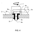
- Figure 4 is a schematic illustration of the third step of turning the sensor according to figure 3 further to achieve release of the tapered flange portion of the elastic member from the through hole such that it engages the sensor attachment member; and
- Figure 5 is a schematic illustration of the unattached sensor and the sensor attachment member according to a second embodiment; and
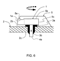
- Figure 6 is a schematic illustration of the first step of inserting the sensor into the through hole of the sensor attachment member according to figure 5; and
- Figure 7 is a schematic illustration of the second step of turning the sensor according to figure 6 to achieve initial engagement between the protruding engagement part of the sensor and the mounting member; and
- Figure 8 is a schematic illustration of the third step of turning the sensor according to figure 7 further to achieve release of the tapered flange portion of the elastic member from the through hole such that it engages the sensor attachment member.
- Still other objects and features of the present invention will become apparent from the following detailed description considered in conjunction with the accompanying drawings. It is to be understood, however, that the drawings are designed solely for purposes of illustration and not as a definition of the limits of the invention, for which reference should be made to the appended claims. It should be further understood that the drawings are not necessarily drawn to scale and that, unless otherwise indicated, they are merely intended to conceptually illustrate the structures and procedures described herein. The same reference numerals will be used for illustrating corresponding features in the different drawings.
- In a preferred first embodiment of the present invention, as shown in FIG. 1, an
elastic member 3 for attaching asensor 1 to asensor attachment member 2 is attached on asensor protruding portion 4 of thesensor 1, and is to be inserted into a throughhole 2a formed in thesensor attachment member 2. On completion of a sensor attaching operation, thesensor 1 can be fixed to the throughhole 2 via theelastic member 3. - As evident from the cross-section view of the
elastic member 3 of FIG. 1, theelastic member 3 has a hollow shape and is attached on thesensor protruding portion 4 on thesensor 1 to cover thesensor protruding portion 4 such that thefore end portion 4a of thesensor protruding portion 4 protrudes from theelastic member 3. Theelastic member 3 further has afirst flange 3a formed on an outer surface on a second end thereof to protrude outwardly in a radial direction thereof. Still further, theelastic member 3 has atapered flange portion 3b on a first end side having a diameter which decreases toward the first end thereof and protrudes outwardly in the radial direction thereof. - The
elastic member 3 is integrally formed from elastic material such as silicone rubber. It should be noted that the material employable for theelastic member 3 should not be limited only to silicon rubber. Alternatively, various kinds of rubber, e. g., fluoric rubber, acrylic rubber, Fluor silicon rubber, ethylene propylene rubber (EPDM), acrylonitrile-butadiene rubber (NBR) and acrylonitrile-butadiene rubber containing hydrogen added thereto (H-NBR) may be employed as the material for theelastic member 3. Additionally, theelastic member 3 may be made of a material other than rubber, provided that the material has adequate elasticity. - Next, a method for attaching the
sensor 1 to thesensor attachment member 2 in this first embodiment will be explained in more detail. The process includes three steps, i.e., an insertion step (which is referred to as a first step), an intermediate turning step (which is referred to as a second step), and a final turning step (which is referred to as a third step). - As illustrated in FIG: 2, in the inserting step, the
elastic member 3 holding thesensor protruding portion 4a therein is inserted into thethrough hole 2a of thesensor attachment member 2 until thefirst flange 3a abuts afirst side surface 2b of thesensor attachment member 2. This insertion will render thetapered flange portion 3b at least partially deformed within the throughhole 2a. - In the intermediate turning step, as illustrated in FIG. 2 and FIG. 3, while the above-mentioned inserted state is maintained, the
sensor 1 is turned in a first direction (illustrated by the broken arrow of FIG. 2) around a centre axis of thetrough hole 2a. Thesensor 1 is turned such that at least oneprotruding engagement part 1a of thesensor 1 engages at least onemounting member 5, which is arranged adjacent the throughhole 2a at thefirst side surface 2b of thesensor attachment member 2. Themounting member 5 is suitably arranged as a locking bridge, as illustrated in FIGS. 1 - 4. - The final turning step is a step which is performed such that the
sensor 1 is fixed to thesensor attachment member 4 via theelastic member 1 in a state shown in FIG. 4 by turning thesensor 1 further in the first direction (illustrated by the arrow of FIG. 3) through a predetermined angle. The engagement between themounting member 5 and the protrudingengagement part 1a is arranged to cause a predetermined inserting pressure to be applied and maintained upon thesensor 1 whilst being turned through the predetermined angle. Turning thesensor 1 and the associated theelastic member 3 will cause thetapered flange portion 3b of theelastic member 3 to become released from being deformed within the throughhole 2a. Once released thetapered flange portion 3b is allowed to become enlarged through the elasticity inherent in its material and protrude outwardly in the radial direction of the through hole such that it engages thesecond side surface 2c of thesensor attachment member 2 thereby attaching thesensor 1 to thesensor attachment member 2 as illustrated in FIG. 4, resulting in a sealing airtight attachment of thesensor 1 to thesensor attachment member 2. - The protruding
engagement part 1a will in the final turning step through the engagement with themounting member 5 be forcing theentire sensor 1 to be inserted further into thetrough hole 2a as a result of being clamped between thelower rim 5a of themounting member 5 during turning of thesensor 1 through the predetermined angle, as illustrated in FIG. 3. - As the
sensor 1 has been turned through the predetermined angle thetapered flange portion 3b of theelastic member 3 will protrude in its entirety from the throughhole 2a. As a result, thesensor protruding portion 4 is fixed in the throughhole 2a of thesensor attachment member 2 via theelastic member 3, as illustrated in FIG. 4. As a result, theelastic member 3 is prevented from disconnecting from the throughhole 2a. - It has been found that the predetermined angle through which the sensor is to be turned should be at least 70 degrees. It should, however, be noted that the appropriate angle, through which the
sensor 1 should be turned in order to release the taperedflange portion 3b, will be dependent on several factors, such as the geometry of theelastic member 3 and in particular the taperedflange portion 3b thereof as well as the properties of the elastic material used therefore. - In order to avoid unnecessary turning of the
sensor 1, which could damage theelastic member 3, the engagement between the mountingmember 5 and the protrudingengagement part 1a should suitably be arranged to restrict further turning of thesensor 1 once thesensor 1 has been turned at least through the predetermined angle. This is suitably done through providing the mountingmember 5 with anend stop 5c, which is arranged to prevent further turning as it is contacted by the protrudingengagement part 1a of thesensor 1. - In order to ensure that no external forces interact with the
sensor 1 upon completion of the mounting thereof to thesensor attachment member 5, the engagement between the mountingmember 5 and the protrudingengagement part 1a should suitably be arranged to be discontinued as turning of thesensor 1 reaches the predetermined angle, such that the predetermined inserting pressure is cancelled. This is suitably done through providing the mountingmember 5 with a cut outsection 5b, which is arranged to receive the protrudingengagement part 1a of thesensor 1, once thesensor 1 has been turned at least through the predetermined angle. - The mounting
member 5 may be provided as an integral part of thesensor attachment member 2, e.g. in the case of an automotive vehicle inlet manifold, cast as an integral part thereof. This is advantageous as the mounting member then also may be assigned additional functions, such as additionally securing thesensor 1 to its mounting position within the throughhole 2a and with suitable design thereof possibly also protecting thesensor 1 physically. Alternatively, the mountingmember 5 may be provided as a separate attachment fixture, which, once thesensor 1 has been attached to thesensor attachment member 2, may be removed and reused for a subsequent mounting operation. - The engagement between the mounting
member 5 and the protrudingengagement part 1a is suitably arranged to provide a confirmation of thesensor 1 having been turned through the predetermined angle as at least one of a tactile, a visual or an audible confirmation. This may is done through arranging the protrudingengagement part 1a of thesensor 1 to snap into the cut outsection 5b of the mountingmember 5, once thesensor 1 has been turned at least through the predetermined angle. - In a second embodiment of the present invention, as shown in FIG. 5, in similar way as in the previous embodiment an
elastic member 3 for attaching asensor 1 to asensor attachment member 2 is attached on asensor protruding portion 4 of thesensor 1, and is to be inserted into a throughhole 2a formed in thesensor attachment member 2. On completion of a sensor attaching operation, thesensor 1 can be fixed to the throughhole 2 via theelastic member 3. - As evident from the cross-section view of the
elastic member 3 of FIG. 5, theelastic member 3 as in the first embodiment has a hollow shape and is attached on thesensor protruding portion 4 on thesensor 1 to cover thesensor protruding portion 4 such that thefore end portion 4a of thesensor protruding portion 4 protrudes from theelastic member 3. Theelastic member 3 further has afirst flange 3a formed on an outer surface on a second end thereof to protrude outwardly in a radial direction thereof. Still further, theelastic member 3 has a taperedflange portion 3b on a first end side having a diameter which decreases toward the first end thereof and protrudes outwardly in the radial direction thereof. - The
elastic member 3 as in the first embodiment is integrally formed from elastic material such as silicone rubber. It should be noted that the material employable for theelastic member 3 should not be limited only to silicon rubber. Alternatively, various kinds of rubber, e.g., fluoric rubber, acrylic rubber, Fluor silicon rubber, ethylene propylene rubber (EPDM), acrylonitrile-butadiene rubber (NBR) and acrylonitrile-butadiene rubber containing hydrogen added thereto (H-NBR) may be employed as the material for theelastic member 3. Additionally, theelastic member 3 may be made of a material other than rubber, provided that the material has adequate elasticity. - Next, a method for attaching the
sensor 1 to thesensor attachment member 2 in this second embodiment will be explained in more detail. The process includes three steps, i.e., an insertion step (which is referred to as a first step), an intermediate turning step (which is referred to as a second step), and a final turning step (which is referred to as a third step). - As illustrated in FIG: 6, in the inserting step, the
elastic member 3 holding thesensor protruding portion 4a therein is inserted into the throughhole 2a of thesensor attachment member 2 until thefirst flange 3a abuts afirst side surface 2b of thesensor attachment member 2. This insertion will render the taperedflange portion 3b at least partially deformed within the throughhole 2a. - In the intermediate turning step, as illustrated in FIG. 6 and FIG. 7, while the above-mentioned inserted state is maintained, the
sensor 1 is turned in a first direction (illustrated by the broken arrow of FIG. 6 and the arrow of FIG. 7) around a centre axis of thetrough hole 2a. Thesensor 1 is turned such that at least one protrudingengagement part 1a of thesensor 1 engages at least one mountingmember 5, which is arranged adjacent the throughhole 2a at thefirst side surface 2b of thesensor attachment member 2. In this second embodiment the protrudingengagement part 1a of thesensor 1 is an extension 1c of the main body of thesensor 1, which extension 1c in FIG. 5 is delimited by the dashed line through thesensor 1. The mountingmember 5 is as in the first embodiment suitably arranged as a locking bridge, as illustrated in FIGS. 5 - 8. - The final turning step is a step which is performed such that the
sensor 1 is fixed to thesensor attachment member 4 via theelastic member 1 in a state shown in FIG. 8 by turning thesensor 1 further in the first direction (illustrated by the arrow of FIG. 7) through a predetermined angle. The engagement between the mountingmember 5 and the protrudingengagement part 1a is arranged to cause a predetermined inserting pressure to be applied and maintained upon thesensor 1 whilst being turned through the predetermined angle. The amount of predetermined inserting pressure is determined by the design of the engagement between the mountingmember 5 and the protrudingengagement part 1a and may be varied from being basically zero, with a very light or no engagement, to a substantial inserting pressure, with severe engagement. The material properties and geometry of theelastic member 3 may be used to determine a suitable inserting pressure, which may then be used as an input for designing the engagement between the mountingmember 5 and the protrudingengagement part 1a. The above is also true for the fist embodiment according to FIGS. 1 - 4. - Turning the
sensor 1 and the associated theelastic member 3 will cause the taperedflange portion 3b of theelastic member 3 to become released from being deformed within the throughhole 2a. Once released the taperedflange portion 3b is allowed to become enlarged through the elasticity inherent in its material and protrude outwardly in the radial direction of the throughhole 2a such that it engages thesecond side surface 2c of thesensor attachment member 2 thereby attaching thesensor 1 to thesensor attachment member 2 as illustrated in FIG. 8, resulting in a sealing airtight attachment of thesensor 1 to thesensor attachment member 2. - The protruding
engagement part 1a, i.e. the extension 1c of the main body of thesensor 1, will in the final turning step through the engagement with the mountingmember 5 be forcing theentire sensor 1 to be inserted further into thetrough hole 2a as a result of being clamped between thelower rim 5a of the mountingmember 5 during turning of thesensor 1 through the predetermined angle, as illustrated in FIG. 7. - As the
sensor 1 has been turned through the predetermined angle the taperedflange portion 3b of theelastic member 3 will protrude in its entirety from the throughhole 2a. As a result, thesensor protruding portion 4 is fixed in the throughhole 2a of thesensor attachment member 2 via theelastic member 3, as illustrated in FIG. 8. As a result, theelastic member 3 is prevented from disconnecting from the throughhole 2a. - As for the first embodiment, it has been found that the predetermined angle through which the sensor is to be turned should be at least 70 degrees. It should, however, be noted that the appropriate angle, through which the
sensor 1 should be turned in order to release the taperedflange portion 3b, will be dependent on several factors, such as the geometry of theelastic member 3 and in particular the taperedflange portion 3b thereof as well as the properties of the elastic material used therefore. - In order to avoid unnecessary turning of the
sensor 1, which could damage theelastic member 3, the engagement between the mountingmember 5 and the protrudingengagement part 1a should suitably be arranged to restrict further turning of thesensor 1 once thesensor 1 has been turned at least through the predetermined angle. This is suitably done through providing the mountingmember 5 with anend stop 5c, which is arranged to prevent further turning as it is contacted by the protrudingengagement part 1a of thesensor 1. - In order to ensure that no external forces interact with the
sensor 1 upon completion of the mounting thereof to thesensor attachment member 5, the engagement between the mountingmember 5 and the protrudingengagement part 1a should suitably be arranged to be discontinued as turning of thesensor 1 reaches the predetermined angle, such that the predetermined inserting pressure is cancelled. This is suitably done through providing the mountingmember 5 with a cut outsection 5b, which is arranged to receive the protrudingengagement part 1a of thesensor 1, once thesensor 1 has been turned at least through the predetermined angle. - The mounting
member 5 may be provided as an integral part of thesensor attachment member 2, e.g. in the case of an automotive vehicle inlet manifold, cast as an integral part thereof. This is advantageous as the mounting member then also may be assigned additional functions, such as additionally securing thesensor 1 to its mounting position within the throughhole 2a and with suitable design thereof possibly also protecting thesensor 1 physically. Alternatively, the mountingmember 5 may be provided as a separate attachment fixture, which, once thesensor 1 has been attached to thesensor attachment member 2, may be removed and reused for a subsequent mounting operation. - The engagement between the mounting
member 5 and the protrudingengagement part 1a is suitably arranged to provide a confirmation of thesensor 1 having been turned through the predetermined angle as at least one of a tactile, a visual or an audible confirmation. This may is done through arranging the protrudingengagement part 1a of thesensor 1 to snap into the cut outsection 5b of the mountingmember 5, once thesensor 1 has been turned at least through the predetermined angle. - The above described method is especially suited for the mounting of so called manifold absolute pressure sensors (MAP sensors) to the intake manifold of automotive vehicles. Thus, the present invention is especially suited to be used for the mounting of sensors to automotive vehicle components within the automotive industry.
- Modifications to embodiments of the invention described in the foregoing are possible without departing from the scope of the invention as defined by the accompanying claims.
- Expressions such as "including", "comprising", "incorporating", "consisting of", "have", "is" used to describe and claim the present invention are intended to be construed in a non-exclusive manner, namely allowing for items, components or elements not explicitly described also to be present. Reference to the singular is also to be construed to relate to the plural and vice versa.
- Numerals included within parentheses in the accompanying claims are intended to assist understanding of the claims and should not be construed in any way to limit subject matter claimed by these claims.
- Thus, while there have been shown and described and pointed out fundamental novel features of the invention as applied to a preferred embodiment thereof, it will be understood that various omissions and substitutions and changes in the form and details of the devices illustrated, and in their operation, may be made by those skilled in the art. For example, it is expressly intended that all combinations of those elements and/or method steps which perform substantially the same function in substantially the same way to achieve the same results are within the scope of the invention. Moreover, it should be recognized that structures and/or elements and/or method steps shown and/or described in connection with any disclosed form or embodiment of the invention may be incorporated in any other disclosed or described or suggested form or embodiment as a general matter of design choice. It is the intention, therefore, to be limited only as indicated by the scope of the claims appended hereto.
Claims (11)
- A method for attaching a sensor (1) to a sensor attachment member (2) via an elastic member (3), having a hollow shape and being attached on a sensor protruding portion (4) on the sensor (1) to cover the sensor protruding portion (4) such that the fore end portion (4a) of the sensor protruding portion (4) protrudes from the elastic member (3), where the elastic member (3) has a first flange (3a) formed on an outer surface on a second end thereof and a tapered flange portion (3b) on a first end side having a diameter which decreases toward the first end thereof, both flanges protruding outwardly in the radial direction thereof; characterised in that it comprises the steps of:inserting the elastic member (3) into a through hole (2a) of the sensor attachment member (2) until the first flange (3a) abuts a first side surface (2b) of the sensor attachment member (2) rendering the tapered flange portion (3b) at least partially deformed within the through hole (2a);turning the sensor (1) in the trough hole (2a) such that at least one protruding engagement part (1a) of the sensor (1) engages at least one mounting member (5) arranged adjacent the through hole, and ;turning the sensor (1) further whereby the engagement between the mounting member (5) and the protruding engagement part (1a) is arranged to cause a predetermined inserting pressure to be applied and maintained upon the sensor (1) whilst being turned through a predetermined angle, causing the tapered flange portion (3b) of the elastic member (3) to be released from the through hole (2a) and expand such that it engages a second side surface (2c) of the sensor attachment member (2).
- A method for attaching a sensor to a sensor attachment member according to claim 1, characterised in that:in the step of turning the sensor (1) further the predetermined angle through which the sensor (1) is turned is at least 70 degrees.
- A method for attaching a sensor to a sensor attachment member according to claim 2, characterised in that it further comprises a step of:arranging the engagement between the mounting member (5) and the protruding engagement part (1 a) to restrict further turning of the sensor (1) once the sensor (1) has been turned at least through the predetermined angle.
- A method for attaching a sensor to a sensor attachment member according to claim 3, characterised in that:in the step of arranging the engagement between the mounting member (5) and the protruding engagement part (1a) to restrict further turning of the sensor (1) once the sensor (1) has been turned at least through the predetermined angle, this is done through providing the mounting member (5) with an end stop (5c), which is arranged to prevent further turning of the sensor (1) upon being contacted by the protruding engagement part (1a) of the sensor (1) once the sensor (1) has been turned at least through the predetermined angle.
- A method for attaching a sensor to a sensor attachment member according to any one of the preceding claims, characterised in that it further comprises the step of:arranging the engagement between the mounting member (5) and the protruding engagement part (1a) to be discontinued, such that the predetermined inserting pressure is cancelled, once the sensor (1) has been turned at least through the predetermined angle.
- A method for attaching a sensor to a sensor attachment member according to claim 5, characterised in that:in the step of arranging the engagement between the mounting member (5) and the protruding engagement part (1a) to be discontinued, such that the predetermined inserting pressure is cancelled, once the sensor (1) has been turned at least through the predetermined angle, this is done through providing the mounting member (5) with a cut out section (5b), which is arranged to receive the protruding engagement part (1a) of the sensor (1), once the sensor (1) has been turned at least through the predetermined angle.
- A method for attaching a sensor to a sensor attachment member according to any one of the preceding claims, characterised in that it further comprises the step of:providing the mounting member (5) as an integral part of the sensor attachment member (2).
- A method for attaching a sensor to a sensor attachment member according to any one of claims 1 to 6, characterised in that it further comprises the step of:providing the mounting member (5) as a separate attachment fixture and removing the mounting member (5) once the sensor (1) has been attached to the sensor attachment member (2).
- A method for attaching a sensor to a sensor attachment member according to any one of the preceding claims, characterised in that it further comprises the step of:arranging the engagement between the mounting member (5) and the protruding engagement part (1a) to provide a confirmation of the sensor (1) having been turned through the predetermined angle as at least one of a tactile, a visual or an audible confirmation.
- A method for attaching a sensor to a sensor attachment member according to claim 9, characterised in that;
in the step of arranging the engagement between the mounting member (5) and the protruding engagement part (1a) to provide a confirmation of the sensor (1) having been turned through the predetermined angle as at least one of a tactile, a visual or an audible confirmation, this is done through arranging the protruding engagement part (1a) of the sensor (1) to snap into the cut out section (5b) of the mounting member (5), once the sensor (1) has been turned at least through the predetermined angle. - A structure for attaching a sensor (1) to a sensor attachment member (2) via an elastic member (3), having a hollow shape and being attached on a sensor protruding portion (4) on the sensor (1) to cover the sensor protruding portion (4) such that the fore end portion (4a) of the sensor protruding portion (4) protrudes from the elastic member (3), where the elastic member (3) has a first flange (3a) formed on an outer surface on a second end thereof and a tapered flange portion (3b) on a first end side having a diameter which decreases toward the first end thereof, both flanges protruding outwardly in the radial direction thereof;
where the elastic member (3) is arranged to be inserted into a through hole (2a) of the sensor attachment member (2) until the first flange (3a) abuts a first side surface (2b) of the sensor attachment member (2) rendering the tapered flange portion (3b) at least partially deformed within the through hole (2a);
characterised in that:the sensor (1) comprises at least one protruding engagement part (1a); andat least one mounting member (5) is arranged adjacent the through hole, and ;the protruding engagement part (1a) upon turning of the sensor (1) in the trough hole (2a) is arranged to engage the mounting member (5); andthe engagement between the mounting member (5) and the protruding engagement part (1a) is arranged to, upon further turning of the sensor (1) through a predetermined angle, cause a predetermined inserting pressure to be applied and maintained upon the sensor (1); andthe tapered flange portion (3b) of the elastic member (3) being arranged to, upon turning of the sensor (1) through the predetermined angle, be released from the through hole (2a) and expand such that it engages a second side surface of the sensor attachment member (2).
Priority Applications (2)
| Application Number | Priority Date | Filing Date | Title |
|---|---|---|---|
| EP20060005681 EP1837631B1 (en) | 2006-03-20 | 2006-03-20 | Method and structure for attaching a sensor to a sensor attachment member |
| DE200660001202 DE602006001202D1 (en) | 2006-03-20 | 2006-03-20 | Method and structure for attaching a sensor to a sensor attachment element |
Applications Claiming Priority (1)
| Application Number | Priority Date | Filing Date | Title |
|---|---|---|---|
| EP20060005681 EP1837631B1 (en) | 2006-03-20 | 2006-03-20 | Method and structure for attaching a sensor to a sensor attachment member |
Publications (2)
| Publication Number | Publication Date |
|---|---|
| EP1837631A1 true EP1837631A1 (en) | 2007-09-26 |
| EP1837631B1 EP1837631B1 (en) | 2008-05-14 |
Family
ID=36699342
Family Applications (1)
| Application Number | Title | Priority Date | Filing Date |
|---|---|---|---|
| EP20060005681 Expired - Lifetime EP1837631B1 (en) | 2006-03-20 | 2006-03-20 | Method and structure for attaching a sensor to a sensor attachment member |
Country Status (2)
| Country | Link |
|---|---|
| EP (1) | EP1837631B1 (en) |
| DE (1) | DE602006001202D1 (en) |
Cited By (2)
| Publication number | Priority date | Publication date | Assignee | Title |
|---|---|---|---|---|
| DE102008001133A1 (en) * | 2008-04-11 | 2009-10-15 | Robert Bosch Gmbh | Sensor fixing device for use in axle or wheel of motor vehicle, has spring locking lugs lockable in recesses under stop-like attachment of sensor head after insertion of sensor into holder and expandable based on spring pressure |
| US10408700B2 (en) * | 2016-09-26 | 2019-09-10 | Nidec Tosok Corporation | Oil pressure sensor attaching structure |
Citations (1)
| Publication number | Priority date | Publication date | Assignee | Title |
|---|---|---|---|---|
| US5945606A (en) * | 1996-08-30 | 1999-08-31 | Desno Corporation | Elastic member, and method and structure for attaching sensor to sensor attachment member using the same |
-
2006
- 2006-03-20 EP EP20060005681 patent/EP1837631B1/en not_active Expired - Lifetime
- 2006-03-20 DE DE200660001202 patent/DE602006001202D1/en not_active Expired - Lifetime
Patent Citations (1)
| Publication number | Priority date | Publication date | Assignee | Title |
|---|---|---|---|---|
| US5945606A (en) * | 1996-08-30 | 1999-08-31 | Desno Corporation | Elastic member, and method and structure for attaching sensor to sensor attachment member using the same |
Cited By (2)
| Publication number | Priority date | Publication date | Assignee | Title |
|---|---|---|---|---|
| DE102008001133A1 (en) * | 2008-04-11 | 2009-10-15 | Robert Bosch Gmbh | Sensor fixing device for use in axle or wheel of motor vehicle, has spring locking lugs lockable in recesses under stop-like attachment of sensor head after insertion of sensor into holder and expandable based on spring pressure |
| US10408700B2 (en) * | 2016-09-26 | 2019-09-10 | Nidec Tosok Corporation | Oil pressure sensor attaching structure |
Also Published As
| Publication number | Publication date |
|---|---|
| EP1837631B1 (en) | 2008-05-14 |
| DE602006001202D1 (en) | 2008-06-26 |
Similar Documents
| Publication | Publication Date | Title |
|---|---|---|
| JP5179295B2 (en) | Temperature sensor mounting device | |
| US20030067122A1 (en) | Thermoplastic gasket with edge bonded rubber apertures and integral alignment grommets | |
| US20080129047A1 (en) | Instant Coupling Device With Locking and/or Disconnection Means | |
| US7552948B2 (en) | Quick connector | |
| JP3944953B2 (en) | Intake device and throttle body for internal combustion engine | |
| US5613549A (en) | Method and apparatus for selectively sealing and securing a sensor of a sealing plug to a part | |
| JP2003511630A (en) | Creep reinforced sensor fixing method | |
| CN111512030B (en) | Device and method for connecting fluid-conducting components | |
| EP1837631B1 (en) | Method and structure for attaching a sensor to a sensor attachment member | |
| US20100300569A1 (en) | Corrugated hose | |
| JP2002087079A (en) | Fuel tank fueling system | |
| EP1867961A1 (en) | Air flow rate measuring device and passage | |
| CN105793621A (en) | Actuator | |
| US20120118086A1 (en) | Sensor assembly | |
| US20100225106A1 (en) | Multifunction fluid connector for automotive vehicle power system | |
| JP2009203901A (en) | Installing structure of air intake component | |
| US6755169B2 (en) | Intake system for an internal-combustion engine | |
| CN101305175B (en) | engine air intake | |
| CN113140929A (en) | Connector with a locking member | |
| JPH1114419A (en) | Intake duct for internal combustion engine | |
| JP6207904B2 (en) | Temperature and humidity measuring device | |
| EP2085130A1 (en) | Retaining Device | |
| US9851123B2 (en) | Flap device for an internal combustion engine or an electric vehicle | |
| US7673622B2 (en) | Air filter, secondary air charging system and seal arrangement for a secondary air charging system | |
| JP4218356B2 (en) | Branch connection |
Legal Events
| Date | Code | Title | Description |
|---|---|---|---|
| PUAI | Public reference made under article 153(3) epc to a published international application that has entered the european phase |
Free format text: ORIGINAL CODE: 0009012 |
|
| AK | Designated contracting states |
Kind code of ref document: A1 Designated state(s): AT BE BG CH CY CZ DE DK EE ES FI FR GB GR HU IE IS IT LI LT LU LV MC NL PL PT RO SE SI SK TR |
|
| AX | Request for extension of the european patent |
Extension state: AL BA HR MK YU |
|
| GRAP | Despatch of communication of intention to grant a patent |
Free format text: ORIGINAL CODE: EPIDOSNIGR1 |
|
| 17P | Request for examination filed |
Effective date: 20070926 |
|
| GRAS | Grant fee paid |
Free format text: ORIGINAL CODE: EPIDOSNIGR3 |
|
| GRAA | (expected) grant |
Free format text: ORIGINAL CODE: 0009210 |
|
| RIN1 | Information on inventor provided before grant (corrected) |
Inventor name: SJOEHOLM, NIKLAS Inventor name: KOEPPEL, ANNA Inventor name: KALLANDER, JONAS Inventor name: CHINI, MAHMOUD Inventor name: SALO, TIMO |
|
| AK | Designated contracting states |
Kind code of ref document: B1 Designated state(s): DE GB SE |
|
| REG | Reference to a national code |
Ref country code: GB Ref legal event code: FG4D |
|
| AKX | Designation fees paid |
Designated state(s): DE GB SE |
|
| REF | Corresponds to: |
Ref document number: 602006001202 Country of ref document: DE Date of ref document: 20080626 Kind code of ref document: P |
|
| REG | Reference to a national code |
Ref country code: SE Ref legal event code: TRGR |
|
| PLBE | No opposition filed within time limit |
Free format text: ORIGINAL CODE: 0009261 |
|
| STAA | Information on the status of an ep patent application or granted ep patent |
Free format text: STATUS: NO OPPOSITION FILED WITHIN TIME LIMIT |
|
| 26N | No opposition filed |
Effective date: 20090217 |
|
| REG | Reference to a national code |
Ref country code: GB Ref legal event code: 732E Free format text: REGISTERED BETWEEN 20111020 AND 20111025 |
|
| REG | Reference to a national code |
Ref country code: DE Ref legal event code: R082 Ref document number: 602006001202 Country of ref document: DE Representative=s name: LOUIS, POEHLAU, LOHRENTZ, DE |
|
| REG | Reference to a national code |
Ref country code: DE Ref legal event code: R081 Ref document number: 602006001202 Country of ref document: DE Owner name: VOLVO CAR CORPORATION, SE Free format text: FORMER OWNER: FORD GLOBAL TECHNOLOGIES, LLC, DEARBORN, MICH., US Effective date: 20120208 Ref country code: DE Ref legal event code: R082 Ref document number: 602006001202 Country of ref document: DE Representative=s name: LOUIS, POEHLAU, LOHRENTZ, DE Effective date: 20120208 Ref country code: DE Ref legal event code: R081 Ref document number: 602006001202 Country of ref document: DE Owner name: VOLVO CAR CORPORATION, SE Free format text: FORMER OWNER: FORD GLOBAL TECHNOLOGIES, LLC, DEARBORN, US Effective date: 20120208 |
|
| PGFP | Annual fee paid to national office [announced via postgrant information from national office to epo] |
Ref country code: GB Payment date: 20150312 Year of fee payment: 10 Ref country code: SE Payment date: 20150326 Year of fee payment: 10 |
|
| REG | Reference to a national code |
Ref country code: SE Ref legal event code: EUG |
|
| GBPC | Gb: european patent ceased through non-payment of renewal fee |
Effective date: 20160320 |
|
| PG25 | Lapsed in a contracting state [announced via postgrant information from national office to epo] |
Ref country code: SE Free format text: LAPSE BECAUSE OF NON-PAYMENT OF DUE FEES Effective date: 20160321 |
|
| PG25 | Lapsed in a contracting state [announced via postgrant information from national office to epo] |
Ref country code: GB Free format text: LAPSE BECAUSE OF NON-PAYMENT OF DUE FEES Effective date: 20160320 |
|
| PGFP | Annual fee paid to national office [announced via postgrant information from national office to epo] |
Ref country code: DE Payment date: 20230221 Year of fee payment: 18 |
|
| REG | Reference to a national code |
Ref country code: DE Ref legal event code: R119 Ref document number: 602006001202 Country of ref document: DE |
|
| PG25 | Lapsed in a contracting state [announced via postgrant information from national office to epo] |
Ref country code: DE Free format text: LAPSE BECAUSE OF NON-PAYMENT OF DUE FEES Effective date: 20241001 |
|
| PG25 | Lapsed in a contracting state [announced via postgrant information from national office to epo] |
Ref country code: DE Free format text: LAPSE BECAUSE OF NON-PAYMENT OF DUE FEES Effective date: 20241001 |