EP1837279A1 - Reinforcement binder - Google Patents
Reinforcement binder Download PDFInfo
- Publication number
- EP1837279A1 EP1837279A1 EP05822838A EP05822838A EP1837279A1 EP 1837279 A1 EP1837279 A1 EP 1837279A1 EP 05822838 A EP05822838 A EP 05822838A EP 05822838 A EP05822838 A EP 05822838A EP 1837279 A1 EP1837279 A1 EP 1837279A1
- Authority
- EP
- European Patent Office
- Prior art keywords
- binding wire
- binding
- reinforcing bar
- warming
- adjustment dial
- Prior art date
- Legal status (The legal status is an assumption and is not a legal conclusion. Google has not performed a legal analysis and makes no representation as to the accuracy of the status listed.)
- Granted
Links
Images


Classifications
-
- E—FIXED CONSTRUCTIONS
- E04—BUILDING
- E04G—SCAFFOLDING; FORMS; SHUTTERING; BUILDING IMPLEMENTS OR AIDS, OR THEIR USE; HANDLING BUILDING MATERIALS ON THE SITE; REPAIRING, BREAKING-UP OR OTHER WORK ON EXISTING BUILDINGS
- E04G21/00—Preparing, conveying, or working-up building materials or building elements in situ; Other devices or measures for constructional work
- E04G21/12—Mounting of reinforcing inserts; Prestressing
- E04G21/122—Machines for joining reinforcing bars
-
- E—FIXED CONSTRUCTIONS
- E04—BUILDING
- E04G—SCAFFOLDING; FORMS; SHUTTERING; BUILDING IMPLEMENTS OR AIDS, OR THEIR USE; HANDLING BUILDING MATERIALS ON THE SITE; REPAIRING, BREAKING-UP OR OTHER WORK ON EXISTING BUILDINGS
- E04G21/00—Preparing, conveying, or working-up building materials or building elements in situ; Other devices or measures for constructional work
- E04G21/12—Mounting of reinforcing inserts; Prestressing
- E04G21/122—Machines for joining reinforcing bars
- E04G21/123—Wire twisting tools
Definitions
- the present invention is related to a reinforcing bar binding machine. More particularly, the present invention is related to a reinforcing bar binding machine having a warming-up function so as to prevent the occurrence of failure in operation in a low temperature environment.
- one or more embodiments of the present invention provide a reinforcing bar binding machine in which no failure in operation is caused even when the reinforcing bar binding machine is used in a cold environment.
- a reinforcing bar binding machine is provided with: a binding wire feed mechanism for forming a binding wire loop round reinforcing bars when a binding wire wound round a reel is sent to a binding wire guide nose; and a binding wire twist mechanism for twisting the binding wire loop so as to bind the reinforcing bars.
- the reinforcing bar binding machine also includes: a usual reinforcing bar binding mode; and a warming-up mode in which the binding wire twist mechanism is driven by a predetermined times, wherein it is possible to select between the reinforcing bar binding mode and the warming-up mode.
- a reinforcing bar binding machine is further provided with a control unit which reads in a setting position of a motor driving adjustment dial and also reads in a state of a trigger lever at the time of turning on a power source switch and which starts a warming-up action in the case where the motor driving adjustment dial is set at a specific setting position and the trigger lever is turned on.
- a method of warming up a reinforcing bar binding machine is provided a step of reciprocating the binding wire twist mechanism by a predetermined times while the binding wire feed mechanism is being maintained in a non-operation state.
- a warming-up operation in which a binding wire cutting mechanism is driven by a predetermined times, is carried out. Therefore, even in an environment of low temperature, it is possible to evade the occurrence of a case in which it is difficult to start a reinforcing bar binding machine due to an increase in the viscosity of lubricant. Accordingly, it is possible to solve a problem in which the performance of the reinforcing bar binding machine is deteriorated when it is used in a cold environment. When not a usual operation cycle of the reinforcing bar binding machine but only a binding wire cutting operation is carried out, the binding wire is not wasted.
- each reference numeral in the drawing shows each component as follows.
- Reference numeral 1 is a reinforcing bar binding machine
- reference numeral 2 is a housing
- reference numeral 3 is a binding wire feed mechanism
- reference numeral 4 is a binding wire twist mechanism
- reference numeral 5 is a grip portion
- reference numeral 6 is a magazine
- reference numeral 7 is a battery pack
- reference numeral 8 is an electric power switch
- reference numeral 9 is a voltage warning LED
- reference numeral 10 is a twist torque setting dial
- reference numeral 11 is a binding wire guide nose
- reference numeral 12 is a trigger lever
- reference numeral 19 is a rotary cutter
- reference numeral 20 is a pin
- reference numeral 21 is a cutter lever
- reference mark R is a reinforcing bar
- reference mark W is a binding wire.
- Fig. 1 is a view showing an electric type reinforcing bar binding machine 1.
- a binding wire feed mechanism 3 and a binding wire twist mechanism 4 are incorporated into a housing 2.
- a binding wire reel (not shown) is charged.
- a battery pack 7 into which NiMH battery is incorporated, is attached.
- the battery pack 7 supplies electric power to a feed motor of the binding wire feed mechanism 3 and a feed motor of the binding wire twist mechanism 4.
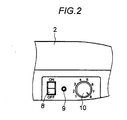
- an electric power source switch 8 As shown in Figs. 1 and 2, there are provided an electric power source switch 8, a warning detection LED 9 and a twist torque adjustment dial 10 on an upper face at the rear of the reinforcing bar binding machine 1.
- a buzzer (not shown) for warning related to voltage is provided in the housing 2.
- graduations from 1 to 8 are indicated in the periphery of the twist torque adj ustment dial 10.
- the binding wire feed mechanism 3 feeds a predetermined length of the binding wire toward the binding wire guide nose 11 arranged on the upside. Then, a forward end portion of the binding wire is cut off with a rotary cutter of a binding wire cutting mechanism described later, so that the forward end portion of the binding wire can be positioned.
- the binding wire twist mechanism 4 conducts a series of actions including a clamping action and a twisting action under the condition that the binding wire twist mechanism 4 does not hold the binding wire.
- the binding wire twist mechanism 4 is stopped at an initial position and put into a standby state. After the binding wire twist mechanism 4 has been put into the standby state, when the trigger lever 12 is pulled, one cycle of the reinforcing bar binding action, which includes a feeding action of the binding wire, a clamping action, a drawing action, a cutting action and a twisting action, is continuously carried out.
- a control portion watches voltage of the battery pack 7 through a voltage detection circuit during a binding action.
- voltage of the battery pack 7 drops to a predetermined voltage at which it is recommended to charge the battery pack 7, the buzzer is made to ring and warning detection LED 9 is turned on so that a reduction of voltage is informed.
- an indicator of the twist torque adjustment dial 10 is adjusted at the graduation 8 and the electric power source switch is turned on under the condition that the trigger lever is pulled, the control portion is put into the warming-up mode described later and a binding wire cutting action is repeatedly carried out by a predetermined times.
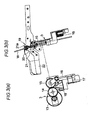
- the binding wire feed mechanism 3 includes: a driving gear 14 having a V-groove that is driven by a feed motor 13; and a driven gear 15 having a V-groove which is meshed with the driving gear 14 having the V-groove.
- a binding wire is sent out being interposed between the driving gear 14 having the V-groove and the driven gear 15 having the V-groove.
- Binding wire W is sent upward from a binding wire reel arranged in the magazine. Binding wire W, which has been sent out from the binding wire reel, is formed into an arcuate shape along a guide groove on an inner circumference of the binding wire guide nose 11 shown in Fig. 1 and goes round reinforcing bars R, and a tip portion of binding wire W threads between the clamps of the binding wire twist mechanism 4.
- the driven gear 15 having the V-groove is attached to a lever 16 and elastically contacted with the driving gear 14 having the V-groove by a spring force generated by a compressive coil spring 17 attached to the lever 16.
- a lower end portion of the lever 16 is pushed to the central side, that is, to the left in Fig. 3(a)
- the driven gear 15 having the V-groove which is attached to an upper portion of the lever 16, is separated from the driving gear 14 having the V-groove arranged on the motor 13 side. Therefore, binding wire W can be threaded between the driving gear 14 having the V-groove and the driven gear 15 having the V-groove.
- a funnel-shaped binding wire guide 18 is provided in a lower portion between the two gears 14 and 15, a funnel-shaped binding wire guide 18 is provided. Binding wire W is threaded into the binding wire guide 18 from below and set between the driving gear 14 having the V-shaped groove and the driven gear 15 having the V-groove.
- a rotary cutter 19 for cutting the binding wire is arranged.
- the rotary cutter 19 includes: a columnar pin 20 in which a groove is formed in the radial direction; and a cutter lever 21 engaged with the pin 20.
- a cutter portion 21a corresponding to the groove of the pin 20 is formed.
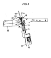
- an end portion of the cutter lever 21 is connected to a slider of the binding wire twist mechanism 4 through a link and moved being linked with the binding wire twist mechanism 4. Therefore, the end portion of the cutter lever 21 rotates in the arrowed direction from the initial position shown in Fig. 3(b) so that the binding wire can be cut. As shown in Fig. 4, after the end portion of the cutter lever 21 has cut off the binding wire, it is returned to the initial position being linked with the binding wire twist mechanism.
- the binding wire twist mechanism 4 includes: a twist shaft not shown in Fig.1; and three clamping plates attached to a forward end portion of the twist shaft.
- the three clamping plates are arranged inside the side cover 23 which is located between the binding wire guide nose 11 and the lower side guard 22.
- Two clamping plates, which are arranged on both sides of the fixed central clamping plate, are opened and closed by a cam mechanism.
- the binding wire is sent out from between the central clamping plate and one of the outside clamping plates.
- the control unit (not shown) stops feeding the binding wire after the binding wire corresponding to the predetermined number of turns has been sent out. At this time, a tip portion of the binding wire reaches a predetermined position in the binding wire guide nose 11.
- the clamping plate of the binding wire twist mechanism 4 clamps a binding wire loop and pulls back the binding wire. At the same time, the binding wire twist mechanism 4 slides and cuts off a rear end of the binding wire loop. Therefore, the binding wire loop is cut away from the successive binding wire.
- the twist shaft of the binding wire twist mechanism 4 and the clamping plate are driven being rotated and a clamp portion of the binding wire loop is twisted, the reinforcing bars are bound.
- twisting operation is stopped. After that, the twist motor is reversed and the clamping plate is opened and the twist shaft is returned to the initial position. In this way, one cycle of the binding step is completed.
- the reinforcing bar binding machine 1 includes a warming-up function.
- the control system is composed as follows. When the electric power source is turned on while the twist torque adjustment dial 10 and the trigger lever 12 (the trigger switch) are being respectively maintained in a specific state, the warming-up mode is attained.
- Fig. 5 is a flow chart showing operation at the time of starting.
- the control unit reads in states of the trigger lever 12 and the twist torque dial 10 (steps 102 and 103).
- a usual initialization action is carried out which includes a binding wire feed action, a binding wire twist mechanism drive action, a binding wire cutting action and an initialization position returning action (step 104).
- the binding machine is put into a state of standby (step 107).
- the binding machine is put into the warming-up mode. Therefore, a reciprocating action of the binding wire twist mechanism 4 is carried out, that is, a binding wire cutting action is carried out (step 105). This action is repeated until the number of the cutting actions reaches 50 times (step 106) . After the binding wire cutting action has been carried out by 50 times, the binding machine is put into the state of standby (step 107) . Due to the above operation, a temperature of grease is raised and viscosity is lowered. Further, a temperature of NiMH battery is also raised and NiMH battery is activated. Therefore, even when the outside temperature is low, it is possible to conduct a normal binding action.
- the motor drive adjustment dial is used as a torque adjustment dial.
- the torque adjustment dial is not limited to the motor drive adjustment dial. An adjustment dial for adjusting a motor rotation or motor speed may be used as the torque adjustment dial.
Landscapes
- Engineering & Computer Science (AREA)
- Architecture (AREA)
- Mechanical Engineering (AREA)
- Civil Engineering (AREA)
- Structural Engineering (AREA)
- Basic Packing Technique (AREA)
- Wire Processing (AREA)
- Ropes Or Cables (AREA)
- Magnetic Resonance Imaging Apparatus (AREA)
- Microwave Amplifiers (AREA)
- Amplifiers (AREA)
- Adhesives Or Adhesive Processes (AREA)
- Vibration Dampers (AREA)
- Forklifts And Lifting Vehicles (AREA)
- Jib Cranes (AREA)
- Perforating, Stamping-Out Or Severing By Means Other Than Cutting (AREA)
Abstract
Description
- The present invention is related to a reinforcing bar binding machine. More particularly, the present invention is related to a reinforcing bar binding machine having a warming-up function so as to prevent the occurrence of failure in operation in a low temperature environment.
- It is a matter of general knowledge to appropriately use lubricant for a rotary shaft, a sliding face of a piston and a frictional face of a gear or a cam in a power tool such as an electric tool or a pneumatic tool. Concerning this matter, for example, refer to
JP-A-2003-136435 - In the case where the reinforcing bar binding machine is used outside where a temperature is very low, the viscosity of grease is increased and a sliding resistance of a rotary shaft or a sliding member is raised. Accordingly, it becomes impossible to exhibit the original performance of the binding machine. In the environment of low temperature, a battery voltage is reduced and an output of a motor is lowered. Accordingly, in addition to the increase in the viscosity of grease, due to the reduction in the battery voltage, an operation speed of amechanismportion is decreased and further an operating force of the mechanism portion becomes weak. Consequently, there is a possibility that failure in operation is caused and further it becomes impossible to start the binding machine.
- Therefore, one or more embodiments of the present invention provide a reinforcing bar binding machine in which no failure in operation is caused even when the reinforcing bar binding machine is used in a cold environment.
- According to one or more embodiments of the present invention, a reinforcing bar binding machine is provided with: a binding wire feed mechanism for forming a binding wire loop round reinforcing bars when a binding wire wound round a reel is sent to a binding wire guide nose; and a binding wire twist mechanism for twisting the binding wire loop so as to bind the reinforcing bars. The reinforcing bar binding machine also includes: a usual reinforcing bar binding mode; and a warming-up mode in which the binding wire twist mechanism is driven by a predetermined times, wherein it is possible to select between the reinforcing bar binding mode and the warming-up mode.
- According to one or more embodiments of the present invention, a reinforcing bar binding machine is further provided with a control unit which reads in a setting position of a motor driving adjustment dial and also reads in a state of a trigger lever at the time of turning on a power source switch and which starts a warming-up action in the case where the motor driving adjustment dial is set at a specific setting position and the trigger lever is turned on.
- According to one or more embodiments of the present invention, a method of warming up a reinforcing bar binding machine is provided a step of reciprocating the binding wire twist mechanism by a predetermined times while the binding wire feed mechanism is being maintained in a non-operation state.
- According to one or more embodiments of the present invention, when a warming-up mode is selected in a reinforcing bar binding machine, a warming-up operation, in which a binding wire cutting mechanism is driven by a predetermined times, is carried out. Therefore, even in an environment of low temperature, it is possible to evade the occurrence of a case in which it is difficult to start a reinforcing bar binding machine due to an increase in the viscosity of lubricant. Accordingly, it is possible to solve a problem in which the performance of the reinforcing bar binding machine is deteriorated when it is used in a cold environment. When not a usual operation cycle of the reinforcing bar binding machine but only a binding wire cutting operation is carried out, the binding wire is not wasted.
- When it is composed in such a manner that a warming-up operation is started by a combination of a setting position of the motor drive adjustment dial and a state of the trigger lever, it becomes unnecessary to provide a specific operation mode selecting switch. Therefore, the number of parts is not increased.
- Other aspects and advantages of the invention will be apparent from the following description and the appended claims.
-
- Fig. 1 is a side view showing a reinforcing bar binding machine.
- Fig. 2 is a plan view showing a power switch portion of the reinforcing bar binding machine.
- Fig. 3(a) is a front view showing a binding wire feed mechanism.
- Fig. 3(b) is a side view showing the binding wire feed mechanism.
- Fig. 4 is a side view showing the binding wire feedmechanism in a state in which a binding wire is cut off.
- Fig. 5 is a flow chart at the time of turning on an electric power source of the reinforcing bar binding machine.
- In this connection, each reference numeral in the drawing shows each component as follows. Reference numeral 1 is a reinforcing bar binding machine,
reference numeral 2 is a housing,reference numeral 3 is a binding wire feed mechanism,reference numeral 4 is a binding wire twist mechanism,reference numeral 5 is a grip portion,reference numeral 6 is a magazine,reference numeral 7 is a battery pack,reference numeral 8 is an electric power switch,reference numeral 9 is a voltage warning LED,reference numeral 10 is a twist torque setting dial,reference numeral 11 is a binding wire guide nose, reference numeral 12 is a trigger lever,reference numeral 19 is a rotary cutter,reference numeral 20 is a pin,reference numeral 21 is a cutter lever, reference mark R is a reinforcing bar and reference mark W is a binding wire. - Referring to the drawings, an embodiment of the present invention will be explained below.
- Fig. 1 is a view showing an electric type reinforcing bar binding machine 1. A binding
wire feed mechanism 3 and a bindingwire twist mechanism 4 are incorporated into ahousing 2. In amagazine 6 arranged in the front of agrip portion 5 of thehousing 2, a binding wire reel (not shown) is charged. To an end portion of thegrip portion 5, abattery pack 7, into which NiMH battery is incorporated, is attached. Through an electric power circuit board (not shown), thebattery pack 7 supplies electric power to a feed motor of the bindingwire feed mechanism 3 and a feed motor of the bindingwire twist mechanism 4. - As shown in Figs. 1 and 2, there are provided an electric
power source switch 8, awarning detection LED 9 and a twisttorque adjustment dial 10 on an upper face at the rear of the reinforcing bar binding machine 1. In thehousing 2, a buzzer (not shown) for warning related to voltage is provided. In the periphery of the twist torqueadj ustment dial 10, graduations from 1 to 8 are indicated. When an indicator of the twisttorque adjustment dial 10 is adjusted at the graduation of 8, the twist torque can be set at the maximum value. - When the
battery pack 7 is attached to the reinforcing bar binding machine 1 and then theelectric power switch 10 is turned on, an initializing action of the reinforcing bar binding machine 1 is carried out. In the initializing action, the bindingwire feed mechanism 3 feeds a predetermined length of the binding wire toward the bindingwire guide nose 11 arranged on the upside. Then, a forward end portion of the binding wire is cut off with a rotary cutter of a binding wire cutting mechanism described later, so that the forward end portion of the binding wire can be positioned. The bindingwire twist mechanism 4 conducts a series of actions including a clamping action and a twisting action under the condition that the bindingwire twist mechanism 4 does not hold the binding wire. After that, the bindingwire twist mechanism 4 is stopped at an initial position and put into a standby state. After the bindingwire twist mechanism 4 has been put into the standby state, when the trigger lever 12 is pulled, one cycle of the reinforcing bar binding action, which includes a feeding action of the binding wire, a clamping action, a drawing action, a cutting action and a twisting action, is continuously carried out. - A control portion watches voltage of the
battery pack 7 through a voltage detection circuit during a binding action. When voltage of thebattery pack 7 drops to a predetermined voltage at which it is recommended to charge thebattery pack 7, the buzzer is made to ring andwarning detection LED 9 is turned on so that a reduction of voltage is informed. When an indicator of the twisttorque adjustment dial 10 is adjusted at thegraduation 8 and the electric power source switch is turned on under the condition that the trigger lever is pulled, the control portion is put into the warming-up mode described later and a binding wire cutting action is repeatedly carried out by a predetermined times. - As shown in Fig.3(a), the binding
wire feed mechanism 3 includes: adriving gear 14 having a V-groove that is driven by afeed motor 13; and a drivengear 15 having a V-groove which is meshed with thedriving gear 14 having the V-groove. A binding wire is sent out being interposed between thedriving gear 14 having the V-groove and the drivengear 15 having the V-groove. Binding wire W is sent upward from a binding wire reel arranged in the magazine. Binding wire W, which has been sent out from the binding wire reel, is formed into an arcuate shape along a guide groove on an inner circumference of the bindingwire guide nose 11 shown in Fig. 1 and goes round reinforcing bars R, and a tip portion of binding wire W threads between the clamps of the bindingwire twist mechanism 4. - The driven
gear 15 having the V-groove is attached to alever 16 and elastically contacted with thedriving gear 14 having the V-groove by a spring force generated by acompressive coil spring 17 attached to thelever 16. When a lower end portion of thelever 16 is pushed to the central side, that is, to the left in Fig. 3(a), the drivengear 15 having the V-groove, which is attached to an upper portion of thelever 16, is separated from thedriving gear 14 having the V-groove arranged on themotor 13 side. Therefore, binding wire W can be threaded between thedriving gear 14 having the V-groove and the drivengear 15 having the V-groove. In a lower portion between the twogears binding wire guide 18 is provided. Binding wire W is threaded into thebinding wire guide 18 from below and set between thedriving gear 14 having the V-shaped groove and the drivengear 15 having the V-groove. - In an upper portion of the binding
wire feed mechanism 3, arotary cutter 19 for cutting the binding wire is arranged. Therotary cutter 19 includes: acolumnar pin 20 in which a groove is formed in the radial direction; and acutter lever 21 engaged with thepin 20. In a pin engaging portion of thecutter lever 21, acutter portion 21a corresponding to the groove of thepin 20 is formed. When the binding wire is threaded into the groove of thepin 20 and then thecutter lever 21 is rotated, acutter portion 21a of thecutter lever 21 shears binding wire W at a position on the outer circumference of thepin 20. - Although not shown in the drawing, an end portion of the
cutter lever 21 is connected to a slider of the bindingwire twist mechanism 4 through a link and moved being linked with the bindingwire twist mechanism 4. Therefore, the end portion of thecutter lever 21 rotates in the arrowed direction from the initial position shown in Fig. 3(b) so that the binding wire can be cut. As shown in Fig. 4, after the end portion of thecutter lever 21 has cut off the binding wire, it is returned to the initial position being linked with the binding wire twist mechanism. - The binding
wire twist mechanism 4 includes: a twist shaft not shown in Fig.1; and three clamping plates attached to a forward end portion of the twist shaft. The three clamping plates are arranged inside theside cover 23 which is located between the bindingwire guide nose 11 and thelower side guard 22. Two clamping plates, which are arranged on both sides of the fixed central clamping plate, are opened and closed by a cam mechanism. - The binding wire is sent out from between the central clamping plate and one of the outside clamping plates. The control unit (not shown) stops feeding the binding wire after the binding wire corresponding to the predetermined number of turns has been sent out. At this time, a tip portion of the binding wire reaches a predetermined position in the binding
wire guide nose 11. The clamping plate of the bindingwire twist mechanism 4 clamps a binding wire loop and pulls back the binding wire. At the same time, the bindingwire twist mechanism 4 slides and cuts off a rear end of the binding wire loop. Therefore, the binding wire loop is cut away from the successive binding wire. Next, when the twist shaft of the bindingwire twist mechanism 4 and the clamping plate are driven being rotated and a clamp portion of the binding wire loop is twisted, the reinforcing bars are bound. When an intensity of twist torque of the twist motor is raised to a predetermined setting value, twisting operation is stopped. After that, the twist motor is reversed and the clamping plate is opened and the twist shaft is returned to the initial position. In this way, one cycle of the binding step is completed. - Next, a warming-up function will be explained below. In the case where the outside air temperature is low, the viscosity of grease coated on the binding
wire twist mechanism 4 is raised, which causes problems in the operation of the bindingwire twist mechanism 4. In order to solve the above problems caused in the environment of low temperature, the reinforcing bar binding machine 1 includes a warming-up function. In this case, the control system is composed as follows. When the electric power source is turned on while the twisttorque adjustment dial 10 and the trigger lever 12 (the trigger switch) are being respectively maintained in a specific state, the warming-up mode is attained. - Fig. 5 is a flow chart showing operation at the time of starting. When the electric
power source switch 8 is turned on (step 101), the control unit reads in states of the trigger lever 12 and the twist torque dial 10 (steps 102 and 103). In the case where the trigger lever 12 is turned off or the twisttorque adjustment dial 10 is set at a graduation except for thegraduation 8, a usual initialization action is carried out which includes a binding wire feed action, a binding wire twist mechanism drive action, a binding wire cutting action and an initialization position returning action (step 104). After the above actions have been carried out, the binding machine is put into a state of standby (step 107). - On the other hand, in the case where the electric power source switch is turned on while the twist
torque adjustment dial 10 is being set at thegraduation 8 and the trigger lever 12 is being pulled, the binding machine is put into the warming-up mode. Therefore, a reciprocating action of the bindingwire twist mechanism 4 is carried out, that is, a binding wire cutting action is carried out (step 105). This action is repeated until the number of the cutting actions reaches 50 times (step 106) . After the binding wire cutting action has been carried out by 50 times, the binding machine is put into the state of standby (step 107) . Due to the above operation, a temperature of grease is raised and viscosity is lowered. Further, a temperature of NiMH battery is also raised and NiMH battery is activated. Therefore, even when the outside temperature is low, it is possible to conduct a normal binding action. - In this warming-up mode, the binding wire is not fed but the binding wire is only cut off. Therefore, the cutting wire is not wasted. In the case where the warming-up operation is stopped for some reasons, only when the electric
power source switch 8 is turned off, the electric power source can be shut off and all actions of the binding machine are stopped. In the above embodiment, the motor drive adjustment dial is used as a torque adjustment dial. However, the torque adjustment dial is not limited to the motor drive adjustment dial. An adjustment dial for adjusting a motor rotation or motor speed may be used as the torque adjustment dial. - In this connection, it should be noted that variations may be made within a scope of the present invention. It is apparent that the present invention can be applied to a power tool except for the reinforcing bar binding machine . In addit ion, it is apparent that these variations or changes can also be included in the scope of the invention.
- The present application is based on
Japanese Patent Application No. 2005-006818 - According to one or more embodiments of the present invention, it is possible to prevent the occurrence of failure in operation when a reinforcing bar binding machine is used in an environment of low temperature.
Claims (4)
- A reinforcing bar binding machine comprising:a binding wire feed mechanism that feeds a binding wire to a binding wire guide nose and forms a binding wire loop around reinforcing bars;a binding wire twist mechanism that twists the binding wire loop and binds the reinforcing bars;a usual reinforcing bar binding mode; anda warming-up mode in which the binding wire twist mechanism is driven by a predetermined times.
- The reinforcing bar binding machine according to claim 1, wherein it is possible to select between the reinforcing bar binding mode and the warming-up mode.
- The reinforcing bar binding machine according to claim 2, further comprising a control unit that reads a settingposition of a motor driving adjustment dial and a state of a trigger lever at the time of turning on a power source switch, and starts a warming-up action in the case where the motor driving adjustment dial is set at a specific setting position and the trigger lever is turned on.
- A method of warming up a reinforcing bar binding machine including a binding wire feed mechanism and a binding wire twist mechanism, the method comprising:reciprocating the binding wire twist mechanism by a predetermined times while the binding wire feed mechanism is being maintained in a non-operation state.
Applications Claiming Priority (2)
| Application Number | Priority Date | Filing Date | Title |
|---|---|---|---|
| JP2005006818A JP4586540B2 (en) | 2005-01-13 | 2005-01-13 | Rebar binding machine |
| PCT/JP2005/024229 WO2006075538A1 (en) | 2005-01-13 | 2005-12-27 | Reinforcement binder |
Publications (3)
| Publication Number | Publication Date |
|---|---|
| EP1837279A1 true EP1837279A1 (en) | 2007-09-26 |
| EP1837279A4 EP1837279A4 (en) | 2009-08-19 |
| EP1837279B1 EP1837279B1 (en) | 2010-11-03 |
Family
ID=36677564
Family Applications (1)
| Application Number | Title | Priority Date | Filing Date |
|---|---|---|---|
| EP05822838A Expired - Lifetime EP1837279B1 (en) | 2005-01-13 | 2005-12-27 | Reinforcement binder |
Country Status (11)
| Country | Link |
|---|---|
| US (1) | US7398800B2 (en) |
| EP (1) | EP1837279B1 (en) |
| JP (1) | JP4586540B2 (en) |
| AT (1) | ATE486783T1 (en) |
| AU (1) | AU2005325095B2 (en) |
| CA (1) | CA2594731C (en) |
| DE (1) | DE602005024617D1 (en) |
| ES (1) | ES2353893T3 (en) |
| NO (1) | NO339527B1 (en) |
| RU (1) | RU2372261C2 (en) |
| WO (1) | WO2006075538A1 (en) |
Cited By (3)
| Publication number | Priority date | Publication date | Assignee | Title |
|---|---|---|---|---|
| USD864688S1 (en) | 2017-03-28 | 2019-10-29 | Signode Industrial Group Llc | Strapping device |
| US10518914B2 (en) | 2008-04-23 | 2019-12-31 | Signode Industrial Group Llc | Strapping device |
| US11999516B2 (en) | 2008-04-23 | 2024-06-04 | Signode Industrial Group Llc | Strapping device |
Families Citing this family (19)
| Publication number | Priority date | Publication date | Assignee | Title |
|---|---|---|---|---|
| JP4396384B2 (en) * | 2004-05-07 | 2010-01-13 | マックス株式会社 | Rebar binding machine |
| JP4961808B2 (en) * | 2006-04-05 | 2012-06-27 | マックス株式会社 | Rebar binding machine |
| JP4760581B2 (en) | 2006-07-12 | 2011-08-31 | 株式会社デンソー | Vehicle operation switch and control method therefor |
| KR101312707B1 (en) * | 2008-07-17 | 2013-10-01 | 시아오지에 이 | An electric hand-held binding apparatus |
| US20100139805A1 (en) * | 2008-12-10 | 2010-06-10 | Panduit Corp. | Power Tool for Stainless Steel Metal Locking Ties |
| TWI516415B (en) | 2008-12-12 | 2016-01-11 | 美克司股份有限公司 | Reinforcing bar binding machine |
| US9597724B2 (en) | 2010-09-02 | 2017-03-21 | Jon R. Kodi | Wire twisting tools and methods |
| US9404275B2 (en) | 2010-11-30 | 2016-08-02 | Pneutools, Incorporated | Reinforcing bar wire tying apparatus |
| CN107210815B (en) * | 2015-02-10 | 2020-07-31 | 布莱特编码技术有限公司 | System and method for providing optically encoded information |
| JP6922221B2 (en) | 2016-12-29 | 2021-08-18 | マックス株式会社 | Cable ties |
| JP6834485B2 (en) * | 2016-12-29 | 2021-02-24 | マックス株式会社 | Cable ties |
| JP6985928B2 (en) * | 2017-12-27 | 2021-12-22 | 株式会社マキタ | Cable ties |
| CN109229478B (en) * | 2018-08-28 | 2021-03-26 | 张丽珠 | Steel wire binding machine |
| US11529669B2 (en) | 2019-12-17 | 2022-12-20 | Makita Corporation | Rebar tying tool |
| JP7703862B2 (en) * | 2021-02-19 | 2025-07-08 | マックス株式会社 | Binding equipment and machines |
| US12479613B2 (en) | 2020-10-05 | 2025-11-25 | Max Co., Ltd. | Binding facility, wire feeding mechanism and binding machine |
| JP2023152250A (en) | 2022-04-01 | 2023-10-16 | 株式会社マキタ | Rebar binding machine |
| JP1768705S (en) * | 2023-06-13 | 2024-04-22 | Rebar Tying Machine | |
| JP1766305S (en) * | 2023-06-13 | 2024-03-25 | Rebar binding machine body |
Family Cites Families (8)
| Publication number | Priority date | Publication date | Assignee | Title |
|---|---|---|---|---|
| US5279336A (en) * | 1992-05-21 | 1994-01-18 | Max Co., Ltd. | Wire binder |
| JP3227693B2 (en) * | 1996-08-02 | 2001-11-12 | マックス株式会社 | Prevention method of wire breakage in rebar tying machine |
| JP2001062744A (en) * | 1999-08-23 | 2001-03-13 | Maeda Metal Industries Ltd | Electric tightening machine and tightening control method therewith |
| AU2002318747B2 (en) * | 2001-07-19 | 2008-02-21 | Max Co., Ltd | Reinforcing steel bar tying machine |
| EP1418124B1 (en) * | 2001-07-25 | 2017-04-19 | Max Co., Ltd. | Reinforcing steel bar tying machine |
| JP3855735B2 (en) | 2001-10-31 | 2006-12-13 | 日立工機株式会社 | Electric tool |
| US20040070369A1 (en) * | 2002-10-11 | 2004-04-15 | Makita Corporation | Adapters for battery chargers |
| JP4144473B2 (en) * | 2003-08-12 | 2008-09-03 | マックス株式会社 | Rebar binding machine cooling device |
-
2005
- 2005-01-13 JP JP2005006818A patent/JP4586540B2/en not_active Expired - Lifetime
- 2005-12-27 CA CA2594731A patent/CA2594731C/en not_active Expired - Lifetime
- 2005-12-27 EP EP05822838A patent/EP1837279B1/en not_active Expired - Lifetime
- 2005-12-27 ES ES05822838T patent/ES2353893T3/en not_active Expired - Lifetime
- 2005-12-27 AT AT05822838T patent/ATE486783T1/en not_active IP Right Cessation
- 2005-12-27 RU RU2007130694/11A patent/RU2372261C2/en active
- 2005-12-27 US US11/795,136 patent/US7398800B2/en not_active Expired - Lifetime
- 2005-12-27 AU AU2005325095A patent/AU2005325095B2/en not_active Expired
- 2005-12-27 WO PCT/JP2005/024229 patent/WO2006075538A1/en not_active Ceased
- 2005-12-27 DE DE602005024617T patent/DE602005024617D1/en not_active Expired - Lifetime
-
2007
- 2007-07-12 NO NO20073611A patent/NO339527B1/en unknown
Cited By (11)
| Publication number | Priority date | Publication date | Assignee | Title |
|---|---|---|---|---|
| US10518914B2 (en) | 2008-04-23 | 2019-12-31 | Signode Industrial Group Llc | Strapping device |
| US11530059B2 (en) | 2008-04-23 | 2022-12-20 | Signode Industrial Group Llc | Strapping device |
| US11731794B2 (en) | 2008-04-23 | 2023-08-22 | Signode Industrial Group Llc | Strapping device |
| US11999516B2 (en) | 2008-04-23 | 2024-06-04 | Signode Industrial Group Llc | Strapping device |
| US12221238B2 (en) | 2008-04-23 | 2025-02-11 | Signode Industrial Group Llc | Strapping device |
| USD889229S1 (en) | 2017-01-30 | 2020-07-07 | Signode Industrial Group Llc | Strapping device |
| USD904151S1 (en) | 2017-01-30 | 2020-12-08 | Signode Industrial Group Llc | Strapping device |
| USD917997S1 (en) | 2017-01-30 | 2021-05-04 | Signode Industrial Group Llc | Strapping device |
| USD928577S1 (en) | 2017-01-30 | 2021-08-24 | Signode Industrial Group Llc | Strapping device |
| USD864688S1 (en) | 2017-03-28 | 2019-10-29 | Signode Industrial Group Llc | Strapping device |
| USD874897S1 (en) | 2017-03-28 | 2020-02-11 | Signode Industrial Group Llc | Strapping device |
Also Published As
| Publication number | Publication date |
|---|---|
| JP2006193979A (en) | 2006-07-27 |
| RU2372261C2 (en) | 2009-11-10 |
| ATE486783T1 (en) | 2010-11-15 |
| NO20073611L (en) | 2007-10-02 |
| AU2005325095B2 (en) | 2011-04-07 |
| EP1837279B1 (en) | 2010-11-03 |
| WO2006075538A1 (en) | 2006-07-20 |
| NO339527B1 (en) | 2016-12-27 |
| CA2594731A1 (en) | 2006-07-20 |
| AU2005325095A1 (en) | 2006-07-20 |
| ES2353893T3 (en) | 2011-03-08 |
| JP4586540B2 (en) | 2010-11-24 |
| DE602005024617D1 (en) | 2010-12-16 |
| CA2594731C (en) | 2010-02-23 |
| US7398800B2 (en) | 2008-07-15 |
| RU2007130694A (en) | 2009-02-20 |
| US20080006341A1 (en) | 2008-01-10 |
| EP1837279A4 (en) | 2009-08-19 |
Similar Documents
| Publication | Publication Date | Title |
|---|---|---|
| US7398800B2 (en) | Reinforcing bar binding machine | |
| EP1775400B1 (en) | Reinforcement binding machine | |
| EP1900640B1 (en) | Reinforcing bar binding machine | |
| US5279336A (en) | Wire binder | |
| US7140400B2 (en) | Reinforcing bar-binding machine | |
| EP1840030A1 (en) | Reinforcing rod binding machine | |
| JP4144473B2 (en) | Rebar binding machine cooling device | |
| JP5013911B2 (en) | Electric tool | |
| JP2004142782A (en) | Reinforcement bundler | |
| JP2005127134A (en) | Reinforcement binder |
Legal Events
| Date | Code | Title | Description |
|---|---|---|---|
| PUAI | Public reference made under article 153(3) epc to a published international application that has entered the european phase |
Free format text: ORIGINAL CODE: 0009012 |
|
| 17P | Request for examination filed |
Effective date: 20070706 |
|
| AK | Designated contracting states |
Kind code of ref document: A1 Designated state(s): AT BE BG CH CY CZ DE DK EE ES FI FR GB GR HU IE IS IT LI LT LU LV MC NL PL PT RO SE SI SK TR |
|
| DAX | Request for extension of the european patent (deleted) | ||
| A4 | Supplementary search report drawn up and despatched |
Effective date: 20090722 |
|
| 17Q | First examination report despatched |
Effective date: 20090929 |
|
| GRAP | Despatch of communication of intention to grant a patent |
Free format text: ORIGINAL CODE: EPIDOSNIGR1 |
|
| GRAS | Grant fee paid |
Free format text: ORIGINAL CODE: EPIDOSNIGR3 |
|
| GRAA | (expected) grant |
Free format text: ORIGINAL CODE: 0009210 |
|
| AK | Designated contracting states |
Kind code of ref document: B1 Designated state(s): AT BE BG CH CY CZ DE DK EE ES FI FR GB GR HU IE IS IT LI LT LU LV MC NL PL PT RO SE SI SK TR |
|
| REG | Reference to a national code |
Ref country code: GB Ref legal event code: FG4D |
|
| REG | Reference to a national code |
Ref country code: CH Ref legal event code: EP |
|
| REG | Reference to a national code |
Ref country code: IE Ref legal event code: FG4D |
|
| REF | Corresponds to: |
Ref document number: 602005024617 Country of ref document: DE Date of ref document: 20101216 Kind code of ref document: P |
|
| REG | Reference to a national code |
Ref country code: SE Ref legal event code: TRGR |
|
| REG | Reference to a national code |
Ref country code: ES Ref legal event code: FG2A Effective date: 20110224 |
|
| REG | Reference to a national code |
Ref country code: NL Ref legal event code: VDEP Effective date: 20101103 |
|
| LTIE | Lt: invalidation of european patent or patent extension |
Effective date: 20101103 |
|
| PG25 | Lapsed in a contracting state [announced via postgrant information from national office to epo] |
Ref country code: LT Free format text: LAPSE BECAUSE OF FAILURE TO SUBMIT A TRANSLATION OF THE DESCRIPTION OR TO PAY THE FEE WITHIN THE PRESCRIBED TIME-LIMIT Effective date: 20101103 |
|
| PG25 | Lapsed in a contracting state [announced via postgrant information from national office to epo] |
Ref country code: PT Free format text: LAPSE BECAUSE OF FAILURE TO SUBMIT A TRANSLATION OF THE DESCRIPTION OR TO PAY THE FEE WITHIN THE PRESCRIBED TIME-LIMIT Effective date: 20110303 Ref country code: NL Free format text: LAPSE BECAUSE OF FAILURE TO SUBMIT A TRANSLATION OF THE DESCRIPTION OR TO PAY THE FEE WITHIN THE PRESCRIBED TIME-LIMIT Effective date: 20101103 Ref country code: FI Free format text: LAPSE BECAUSE OF FAILURE TO SUBMIT A TRANSLATION OF THE DESCRIPTION OR TO PAY THE FEE WITHIN THE PRESCRIBED TIME-LIMIT Effective date: 20101103 Ref country code: SI Free format text: LAPSE BECAUSE OF FAILURE TO SUBMIT A TRANSLATION OF THE DESCRIPTION OR TO PAY THE FEE WITHIN THE PRESCRIBED TIME-LIMIT Effective date: 20101103 Ref country code: BG Free format text: LAPSE BECAUSE OF FAILURE TO SUBMIT A TRANSLATION OF THE DESCRIPTION OR TO PAY THE FEE WITHIN THE PRESCRIBED TIME-LIMIT Effective date: 20110203 Ref country code: AT Free format text: LAPSE BECAUSE OF FAILURE TO SUBMIT A TRANSLATION OF THE DESCRIPTION OR TO PAY THE FEE WITHIN THE PRESCRIBED TIME-LIMIT Effective date: 20101103 Ref country code: LV Free format text: LAPSE BECAUSE OF FAILURE TO SUBMIT A TRANSLATION OF THE DESCRIPTION OR TO PAY THE FEE WITHIN THE PRESCRIBED TIME-LIMIT Effective date: 20101103 Ref country code: IS Free format text: LAPSE BECAUSE OF FAILURE TO SUBMIT A TRANSLATION OF THE DESCRIPTION OR TO PAY THE FEE WITHIN THE PRESCRIBED TIME-LIMIT Effective date: 20110303 |
|
| PG25 | Lapsed in a contracting state [announced via postgrant information from national office to epo] |
Ref country code: GR Free format text: LAPSE BECAUSE OF FAILURE TO SUBMIT A TRANSLATION OF THE DESCRIPTION OR TO PAY THE FEE WITHIN THE PRESCRIBED TIME-LIMIT Effective date: 20110204 |
|
| PG25 | Lapsed in a contracting state [announced via postgrant information from national office to epo] |
Ref country code: CZ Free format text: LAPSE BECAUSE OF FAILURE TO SUBMIT A TRANSLATION OF THE DESCRIPTION OR TO PAY THE FEE WITHIN THE PRESCRIBED TIME-LIMIT Effective date: 20101103 Ref country code: BE Free format text: LAPSE BECAUSE OF FAILURE TO SUBMIT A TRANSLATION OF THE DESCRIPTION OR TO PAY THE FEE WITHIN THE PRESCRIBED TIME-LIMIT Effective date: 20101103 Ref country code: EE Free format text: LAPSE BECAUSE OF FAILURE TO SUBMIT A TRANSLATION OF THE DESCRIPTION OR TO PAY THE FEE WITHIN THE PRESCRIBED TIME-LIMIT Effective date: 20101103 Ref country code: MC Free format text: LAPSE BECAUSE OF NON-PAYMENT OF DUE FEES Effective date: 20101231 |
|
| REG | Reference to a national code |
Ref country code: CH Ref legal event code: PL |
|
| PG25 | Lapsed in a contracting state [announced via postgrant information from national office to epo] |
Ref country code: DK Free format text: LAPSE BECAUSE OF FAILURE TO SUBMIT A TRANSLATION OF THE DESCRIPTION OR TO PAY THE FEE WITHIN THE PRESCRIBED TIME-LIMIT Effective date: 20101103 Ref country code: RO Free format text: LAPSE BECAUSE OF FAILURE TO SUBMIT A TRANSLATION OF THE DESCRIPTION OR TO PAY THE FEE WITHIN THE PRESCRIBED TIME-LIMIT Effective date: 20101103 Ref country code: PL Free format text: LAPSE BECAUSE OF FAILURE TO SUBMIT A TRANSLATION OF THE DESCRIPTION OR TO PAY THE FEE WITHIN THE PRESCRIBED TIME-LIMIT Effective date: 20101103 Ref country code: SK Free format text: LAPSE BECAUSE OF FAILURE TO SUBMIT A TRANSLATION OF THE DESCRIPTION OR TO PAY THE FEE WITHIN THE PRESCRIBED TIME-LIMIT Effective date: 20101103 |
|
| PLBE | No opposition filed within time limit |
Free format text: ORIGINAL CODE: 0009261 |
|
| STAA | Information on the status of an ep patent application or granted ep patent |
Free format text: STATUS: NO OPPOSITION FILED WITHIN TIME LIMIT |
|
| 26N | No opposition filed |
Effective date: 20110804 |
|
| PG25 | Lapsed in a contracting state [announced via postgrant information from national office to epo] |
Ref country code: IE Free format text: LAPSE BECAUSE OF NON-PAYMENT OF DUE FEES Effective date: 20101227 Ref country code: LI Free format text: LAPSE BECAUSE OF NON-PAYMENT OF DUE FEES Effective date: 20101231 Ref country code: CH Free format text: LAPSE BECAUSE OF NON-PAYMENT OF DUE FEES Effective date: 20101231 |
|
| REG | Reference to a national code |
Ref country code: DE Ref legal event code: R097 Ref document number: 602005024617 Country of ref document: DE Effective date: 20110804 |
|
| PG25 | Lapsed in a contracting state [announced via postgrant information from national office to epo] |
Ref country code: IT Free format text: LAPSE BECAUSE OF FAILURE TO SUBMIT A TRANSLATION OF THE DESCRIPTION OR TO PAY THE FEE WITHIN THE PRESCRIBED TIME-LIMIT Effective date: 20101103 |
|
| PG25 | Lapsed in a contracting state [announced via postgrant information from national office to epo] |
Ref country code: CY Free format text: LAPSE BECAUSE OF FAILURE TO SUBMIT A TRANSLATION OF THE DESCRIPTION OR TO PAY THE FEE WITHIN THE PRESCRIBED TIME-LIMIT Effective date: 20101103 |
|
| PG25 | Lapsed in a contracting state [announced via postgrant information from national office to epo] |
Ref country code: LU Free format text: LAPSE BECAUSE OF NON-PAYMENT OF DUE FEES Effective date: 20101227 Ref country code: HU Free format text: LAPSE BECAUSE OF FAILURE TO SUBMIT A TRANSLATION OF THE DESCRIPTION OR TO PAY THE FEE WITHIN THE PRESCRIBED TIME-LIMIT Effective date: 20110504 |
|
| PG25 | Lapsed in a contracting state [announced via postgrant information from national office to epo] |
Ref country code: TR Free format text: LAPSE BECAUSE OF FAILURE TO SUBMIT A TRANSLATION OF THE DESCRIPTION OR TO PAY THE FEE WITHIN THE PRESCRIBED TIME-LIMIT Effective date: 20101103 |
|
| REG | Reference to a national code |
Ref country code: FR Ref legal event code: PLFP Year of fee payment: 11 |
|
| REG | Reference to a national code |
Ref country code: FR Ref legal event code: PLFP Year of fee payment: 12 |
|
| REG | Reference to a national code |
Ref country code: FR Ref legal event code: PLFP Year of fee payment: 13 |
|
| PGFP | Annual fee paid to national office [announced via postgrant information from national office to epo] |
Ref country code: DE Payment date: 20241029 Year of fee payment: 20 |
|
| PGFP | Annual fee paid to national office [announced via postgrant information from national office to epo] |
Ref country code: GB Payment date: 20241107 Year of fee payment: 20 |
|
| PGFP | Annual fee paid to national office [announced via postgrant information from national office to epo] |
Ref country code: FR Payment date: 20241111 Year of fee payment: 20 |
|
| PGFP | Annual fee paid to national office [announced via postgrant information from national office to epo] |
Ref country code: SE Payment date: 20241114 Year of fee payment: 20 |
|
| PGFP | Annual fee paid to national office [announced via postgrant information from national office to epo] |
Ref country code: ES Payment date: 20250103 Year of fee payment: 20 |
|
| REG | Reference to a national code |
Ref country code: DE Ref legal event code: R071 Ref document number: 602005024617 Country of ref document: DE |
|
| REG | Reference to a national code |
Ref country code: ES Ref legal event code: FD2A Effective date: 20260107 |
|
| REG | Reference to a national code |
Ref country code: GB Ref legal event code: PE20 Expiry date: 20251226 |
|
| PG25 | Lapsed in a contracting state [announced via postgrant information from national office to epo] |
Ref country code: ES Free format text: LAPSE BECAUSE OF EXPIRATION OF PROTECTION Effective date: 20251228 |
|
| REG | Reference to a national code |
Ref country code: SE Ref legal event code: EUG |