EP1836873B1 - Loudspeaker with cooling system to increase the output power - Google Patents
Loudspeaker with cooling system to increase the output power Download PDFInfo
- Publication number
- EP1836873B1 EP1836873B1 EP06701632A EP06701632A EP1836873B1 EP 1836873 B1 EP1836873 B1 EP 1836873B1 EP 06701632 A EP06701632 A EP 06701632A EP 06701632 A EP06701632 A EP 06701632A EP 1836873 B1 EP1836873 B1 EP 1836873B1
- Authority
- EP
- European Patent Office
- Prior art keywords
- pole plate
- holes
- back pole
- cup
- loudspeaker
- Prior art date
- Legal status (The legal status is an assumption and is not a legal conclusion. Google has not performed a legal analysis and makes no representation as to the accuracy of the status listed.)
- Expired - Lifetime
Links
Images


Classifications
-
- H—ELECTRICITY
- H04—ELECTRIC COMMUNICATION TECHNIQUE
- H04R—LOUDSPEAKERS, MICROPHONES, GRAMOPHONE PICK-UPS OR LIKE ACOUSTIC ELECTROMECHANICAL TRANSDUCERS; ELECTRIC HEARING AIDS; PUBLIC ADDRESS SYSTEMS
- H04R9/00—Transducers of moving-coil, moving-strip, or moving-wire type
- H04R9/02—Details
- H04R9/022—Cooling arrangements
Definitions
- This invention relates generally to a dynamic loudspeaker with recycle system having a sufficient air movement.
- the power compression problem (as illustrated in CHART 1) describes the voice coil temperature and electric power plots of a loudspeaker under maximum power. Test period: 60 seconds. Type of applied signal: 120 Hz sinusoid. Applied power: 154 watts. - The electric charts values are measured with SpeakerLAB: automatic system of measure for loudspeaker thermal and power test, projected and built by the same author-
- TABLE 1 shows the difference between final and initial value of temperature ( ⁇ T) and power values ( ⁇ P).
- ⁇ T final and initial value of temperature
- ⁇ P power values
- CHART 1 represent the electric power compression while CHART 2 shows acoustic power compression of the loudspeaker.
- the loudspeaker used in tests is a standard woofer, with support 8 of the voice coil lengthened, it provided with holes 3 in the back pole plate 2 and in front pole plate 4, but without cap 1 (as illustrated in FIG. 1 and FIG. 2 ).
- TABLE 4 and TABLE 5 shows electric and acoustic power compression of the loudspeaker respectively with and without recycle system (SdR).
- the analysis show absolute value of the relative difference (
- FIG. 7 and FIG. 8 reported the case in which, for technical or construction loudspeaker characteristic, a workmanship of the anterior pole plate is not possible or too to perform holes on such plate, the recycle of the air could be used to cool voice coil by a different profile of the cap.
- This woofer doesn't have the lengthened support of voice coil and it is deprived of thickness.
- the modified cap leaves a part of holes of the back pole plate open, in such way the air flow, pushed in (compression phase, illustrated in FIG. 9 ) from the dust cap through the back pole plate nucleus hole, is made to converge by the cap through internal holes in the cap, to after escape from the external holes in the cap.
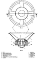
- FIG. 1 is a back view of a woofer with cap.
- FIG. 2 is a cross-sectional view of a woofer with cap.
- FIG. 3 is a back view of woofer with cap.
- FIG. 4 is a cross-sectional view of woofer in FIG. 2 , with pole plates illustrated.
- FIG. 5 is a cross-sectional view of woofer with cap and illustrated air movement during compression stage.
- FIG. 6 is a cross-sectional view of woofer with cap and illustrated air movement during expansion stage.
- FIG. 7 is a back view of a woofer with modified cap.
- FIG. 8 is a cross-sectional view of woofer with modified cap, with pole plates illustrated.
- FIG. 9 is a cross-sectional view of woofer with modified cap and illustrated air movement during compression stage.
- FIG. 10 is a cross-sectional view of woofer with modified cap and illustrated air movement during expansion stage.
Landscapes
- Physics & Mathematics (AREA)
- Engineering & Computer Science (AREA)
- Acoustics & Sound (AREA)
- Signal Processing (AREA)
- Audible-Bandwidth Dynamoelectric Transducers Other Than Pickups (AREA)
Description
- 1. Cross-References to Related Application.
- This application claims priority to
IT Utility Model Application, Serial No. FO2005U000001 - 2. Field of the Invention.
- This invention relates generally to a dynamic loudspeaker with recycle system having a sufficient air movement.
- 3. Related Art.
- To the actual state of technique applying to the clamps of a loudspeaker an high level electric signal causes damage due to thermal limits (components' overheating) and mechanics limits (excursion of the mobile parts elevated). Moreover the maximum power handle by a loudspeaker is proportional to the maximum temperature that its voice coil can reach. Overheating components loudspeaker also causes another problem: the power compression, that represent the reduction of power during the loudspeaker action in the time.
- The power compression problem (as illustrated in CHART 1) describes the voice coil temperature and electric power plots of a loudspeaker under maximum power. Test period: 60 seconds. Type of applied signal: 120 Hz sinusoid. Applied power: 154 watts. - The electric charts values are measured with SpeakerLAB: automatic system of measure for loudspeaker thermal and power test, projected and built by the same author-

- Test start at voice coil temperature of 18 °C, after 1 minute report 115 °C; in the same time the electric power start at value of 155 Watts, after 1 minute report a value of 119 Watts.
- TABLE 1 shows the difference between final and initial value of temperature (ΔT) and power values (ΔP).
TABLE 1 VARIATION ΔT [°C] +97 ΔP [W] -36 - CHART 1 represent the electric power compression while CHART 2 shows acoustic power compression of the loudspeaker.

- Contemporarily the previous measure, microphone -at 1 meter on loudspeaker axis- records a 2.6 dB loss (TABLE 2).
TABLE 2 VARIATION PC [dB] -2.6 - The loudspeaker used in tests is a standard woofer, with
support 8 of the voice coil lengthened, it provided withholes 3 in theback pole plate 2 and infront pole plate 4, but without cap 1 (as illustrated inFIG. 1 and FIG. 2 ). - Recycling airflow systems are disclosed in
JP-2004/186898 CA-1 2270726.7 - SUMMARY OF THE INVENTION
- It is possible to decrease the power compression and increase the output power of the same woofer forcing the convection cooling on the
voice coil 9; recycling the air flow produced during thedust cap 13 movement and passing through thehole 6 in the nucleus of the back pole plate. - The object of the present invention is achieved by a loudspeaker as disclosed in
claims - This results are obtained with a
metallic cap 1 in woofer added (also illustrated inFIG. 3 and FIG. 4 ). The results of the air flow created through the holes by the cap inFIG. 5 and FIG. 6 are visible. Air flow produces an air recycle that flows throughout the voice coil, cooling it and increasing the loudspeaker performances in electric and acoustics power. -

TABLE 3 VARIATION ΔT [°C] + 57 ΔP [W] -21 - When measures of the same loudspeaker are performed, with the cap placed, a great improvement is obtained (as visible in CHART 3). The temperature of the voice coil in this test varies from 17 °C to 74 °C, thus the electric power as before starts from value of 155 Watts, at the end of 1 minute test is 134 Watts. TABLE 3 shows the results.
- Moreover, the increase of temperature is limited, then there are some advantages in the containment of electric power loss. Important results are showed from electric and acoustic power; in fact the graph of
CHART 4 report the loss of acoustic power limited to 1.3 dB.
- TABLE 4 and TABLE 5 shows electric and acoustic power compression of the loudspeaker respectively with and without recycle system (SdR). The analysis show absolute value of the relative difference (|ΔRel|) of woofer endowed with recycle system, in comparison to the same woofer without recycle system; it illustrates a voice coil temperature attenuation of 40 °C, an increase in electric power of 15 Watts and an increase of acoustic power output of 1.3 dB.
-
TABLE 4 Without SdR with SdR |ΔRel| ΔT [°C] + 97 + 57 40 ΔP [W] -36 -21 15 -
TABLE 5 without SdR with SdR |ΔRel| PC [dB] -2.6 -1.3 1.3 -
FIG. 7 and FIG. 8 reported the case in which, for technical or construction loudspeaker characteristic, a workmanship of the anterior pole plate is not possible or too to perform holes on such plate, the recycle of the air could be used to cool voice coil by a different profile of the cap. - This woofer doesn't have the lengthened support of voice coil and it is deprived of thickness. The only changes performed to the standard woofer, therefore, there are the holes in the back pole plate and the insertion of new cap.
- The modified cap leaves a part of holes of the back pole plate open, in such way the air flow, pushed in (compression phase, illustrated in
FIG. 9 ) from the dust cap through the back pole plate nucleus hole, is made to converge by the cap through internal holes in the cap, to after escape from the external holes in the cap. - In expansion phase the air flow follows the same run, but with opposite verse. The performances results of woofer illustrated in
FIG. 8 are 5% lower in comparison the woofer ofFIG. 4 . - BRIEF DESCRIPTION OF THE DRAWINGS
-
FIG. 1 is a back view of a woofer with cap. -
FIG. 2 is a cross-sectional view of a woofer with cap. -
FIG. 3 is a back view of woofer with cap. -
FIG. 4 is a cross-sectional view of woofer inFIG. 2 , with pole plates illustrated. -
FIG. 5 is a cross-sectional view of woofer with cap and illustrated air movement during compression stage. -
FIG. 6 is a cross-sectional view of woofer with cap and illustrated air movement during expansion stage. -
FIG. 7 is a back view of a woofer with modified cap. -
FIG. 8 is a cross-sectional view of woofer with modified cap, with pole plates illustrated. -
FIG. 9 is a cross-sectional view of woofer with modified cap and illustrated air movement during compression stage. -
FIG. 10 is a cross-sectional view of woofer with modified cap and illustrated air movement during expansion stage.
Claims (2)
- A dynamic loudspeaker with air recycle system comprising:a dust cup (13);a basket (7);a front pole plate (4);a back pole plate (2) comprising a center nucleus, wherein said center nucleus is provided with a through hole (6);a magnet placed on said back pole plate (2), and separated by a air space region from said center nucleus, wherein said back pole plate (2) is provided with through holes (3) in correspondence of said air space region;a cup (1) applied to the underside of said back pole plate (2) arranged so as to cover from outside said hole (6) in the center nucleous and said holes (3) in the back pole plate (2),wherein a spacer (5) is provided between the basket and the front pole plate, said spacer being provided with axial apertures, and
said front pole plate (4) is placed on the magnet and provided with through holes (3) in correspondence of the space region, so that the air flow produced during the dust cap movement is recycled passing through the hole (6) in the nucleus, the holes (3) in the back pole plate (2), the holes (3) in the front pole plate (4) and the axial apertures of said spacer. - A dynamic loudspeaker with air recycle system comprising:a dust cup (13);a back pole plate (2) comprising a center nucleus, wherein said center nucleus is provided with a through hole (6);a magnet placed on said back pole (2), and separated by a air space region from said center nucleus, wherein said back pole plate (2) is provided with through holes (3) in correspondence of said air space region;a cup (1) applied to the underside of said back pole plate (2), wherein said cup is arranged so as to cover from outside said hole (6) in the center nucleus and only a part of said holes (3) in the back pole plate (2), in such way that the air flow pushed in compression phase by the dust cup (13) through said hole (6) of the center nucleus is made to converge by said cup (1) through the part of said holes (3) of the back pole (2) which is covered by the cup (1), to after escape through the part of said holes (3) of the back pole (2) which is not covered by the cup (1).
Applications Claiming Priority (2)
| Application Number | Priority Date | Filing Date | Title |
|---|---|---|---|
| ITFO20050001 ITFO20050001U1 (en) | 2005-01-12 | 2005-01-12 | SPEAKER WITH RECIRCULATION SYSTEM TO INCREASE OUTPUT POWER |
| PCT/IT2006/000010 WO2006075349A1 (en) | 2005-01-12 | 2006-01-11 | Loudspeaker with cooling system to increase the output power |
Publications (2)
| Publication Number | Publication Date |
|---|---|
| EP1836873A1 EP1836873A1 (en) | 2007-09-26 |
| EP1836873B1 true EP1836873B1 (en) | 2010-05-26 |
Family
ID=36087712
Family Applications (1)
| Application Number | Title | Priority Date | Filing Date |
|---|---|---|---|
| EP06701632A Expired - Lifetime EP1836873B1 (en) | 2005-01-12 | 2006-01-11 | Loudspeaker with cooling system to increase the output power |
Country Status (4)
| Country | Link |
|---|---|
| EP (1) | EP1836873B1 (en) |
| DE (1) | DE602006014501D1 (en) |
| IT (1) | ITFO20050001U1 (en) |
| WO (1) | WO2006075349A1 (en) |
Family Cites Families (4)
| Publication number | Priority date | Publication date | Assignee | Title |
|---|---|---|---|---|
| JP3163902B2 (en) * | 1994-06-16 | 2001-05-08 | ソニー株式会社 | Speaker device |
| CA2270726A1 (en) * | 1998-09-08 | 2000-03-08 | The Canadian Loudspeaker Corporation | Loudspeaker |
| CA2245351A1 (en) * | 1998-09-08 | 2000-03-08 | The Canadian Loudspeaker Corporation | Forced air cooling system |
| JP4032946B2 (en) * | 2002-12-02 | 2008-01-16 | ソニー株式会社 | Speaker |
-
2005
- 2005-01-12 IT ITFO20050001 patent/ITFO20050001U1/en unknown
-
2006
- 2006-01-11 EP EP06701632A patent/EP1836873B1/en not_active Expired - Lifetime
- 2006-01-11 DE DE602006014501T patent/DE602006014501D1/en not_active Expired - Lifetime
- 2006-01-11 WO PCT/IT2006/000010 patent/WO2006075349A1/en not_active Ceased
Also Published As
| Publication number | Publication date |
|---|---|
| DE602006014501D1 (en) | 2010-07-08 |
| WO2006075349A1 (en) | 2006-07-20 |
| ITFO20050001U1 (en) | 2005-04-13 |
| WO2006075349B1 (en) | 2006-09-08 |
| EP1836873A1 (en) | 2007-09-26 |
Similar Documents
| Publication | Publication Date | Title |
|---|---|---|
| US5909015A (en) | Self-cooled loudspeaker | |
| CN102892063B (en) | Multiple driver transducer with symmetrical magnetic circuits and symmetric coil circuit | |
| Klippel | Nonlinear modeling of the heat transfer in loudspeakers | |
| US20020044671A1 (en) | Loudspeaker | |
| CN108616795B (en) | A speaker box including an actively cooled speaker | |
| CN105376671B (en) | A speaker and terminal | |
| US11611830B2 (en) | Audio transducer with forced ventilation of motor and method | |
| WO2018095033A1 (en) | Speaker unit and speaker module | |
| Klippel | Diagnosis and remedy of nonlinearities in electrodynamical transducers | |
| Small | Vented-box loudspeaker systems, part III: Synthesis | |
| US5933512A (en) | Double cone-type loudspeaker | |
| CN110166900A (en) | Vibrating diaphragm, its production method and the sounding device including the vibrating diaphragm | |
| CN201118899Y (en) | Speaker basin rack with set heat radiation hole | |
| JP4032946B2 (en) | Speaker | |
| JP2019518389A (en) | Electro-acoustic transducer, alignment element of electro-acoustic transducer, and method of assembling electro-acoustic transducer | |
| WO2006075349A1 (en) | Loudspeaker with cooling system to increase the output power | |
| CN205605430U (en) | Compressor | |
| CN113873411B (en) | Quick assembly structure of loudspeaker and assembly method thereof | |
| CN108174332B (en) | Loudspeaker module | |
| EP1233645A2 (en) | Loudspeaker pole piece and loudspeaker assembly | |
| JP3163902B2 (en) | Speaker device | |
| CN213073066U (en) | Special damping heat dissipation type five metals basin frame of accurate speaker | |
| CN104429099A (en) | Method and apparatus for controlling the operating temperature of a loudspeaker | |
| CN223957654U (en) | Double voice coil device of loudspeaker | |
| CN108449694B (en) | Vibrating diaphragm and telephone receiver |
Legal Events
| Date | Code | Title | Description |
|---|---|---|---|
| PUAI | Public reference made under article 153(3) epc to a published international application that has entered the european phase |
Free format text: ORIGINAL CODE: 0009012 |
|
| 17P | Request for examination filed |
Effective date: 20070712 |
|
| AK | Designated contracting states |
Kind code of ref document: A1 Designated state(s): DE DK ES FR GB NL |
|
| DAX | Request for extension of the european patent (deleted) | ||
| RBV | Designated contracting states (corrected) |
Designated state(s): DE DK ES FR GB NL |
|
| 17Q | First examination report despatched |
Effective date: 20080414 |
|
| GRAP | Despatch of communication of intention to grant a patent |
Free format text: ORIGINAL CODE: EPIDOSNIGR1 |
|
| GRAS | Grant fee paid |
Free format text: ORIGINAL CODE: EPIDOSNIGR3 |
|
| GRAA | (expected) grant |
Free format text: ORIGINAL CODE: 0009210 |
|
| AK | Designated contracting states |
Kind code of ref document: B1 Designated state(s): DE DK ES FR GB NL |
|
| REG | Reference to a national code |
Ref country code: GB Ref legal event code: FG4D |
|
| REF | Corresponds to: |
Ref document number: 602006014501 Country of ref document: DE Date of ref document: 20100708 Kind code of ref document: P |
|
| REG | Reference to a national code |
Ref country code: NL Ref legal event code: VDEP Effective date: 20100526 |
|
| PG25 | Lapsed in a contracting state [announced via postgrant information from national office to epo] |
Ref country code: NL Free format text: LAPSE BECAUSE OF FAILURE TO SUBMIT A TRANSLATION OF THE DESCRIPTION OR TO PAY THE FEE WITHIN THE PRESCRIBED TIME-LIMIT Effective date: 20100526 Ref country code: DK Free format text: LAPSE BECAUSE OF FAILURE TO SUBMIT A TRANSLATION OF THE DESCRIPTION OR TO PAY THE FEE WITHIN THE PRESCRIBED TIME-LIMIT Effective date: 20100526 |
|
| PLBE | No opposition filed within time limit |
Free format text: ORIGINAL CODE: 0009261 |
|
| STAA | Information on the status of an ep patent application or granted ep patent |
Free format text: STATUS: NO OPPOSITION FILED WITHIN TIME LIMIT |
|
| 26N | No opposition filed |
Effective date: 20110301 |
|
| REG | Reference to a national code |
Ref country code: DE Ref legal event code: R097 Ref document number: 602006014501 Country of ref document: DE Effective date: 20110228 |
|
| PG25 | Lapsed in a contracting state [announced via postgrant information from national office to epo] |
Ref country code: ES Free format text: LAPSE BECAUSE OF FAILURE TO SUBMIT A TRANSLATION OF THE DESCRIPTION OR TO PAY THE FEE WITHIN THE PRESCRIBED TIME-LIMIT Effective date: 20100906 |
|
| PGFP | Annual fee paid to national office [announced via postgrant information from national office to epo] |
Ref country code: DE Payment date: 20140129 Year of fee payment: 9 |
|
| PGFP | Annual fee paid to national office [announced via postgrant information from national office to epo] |
Ref country code: FR Payment date: 20140122 Year of fee payment: 9 |
|
| PGFP | Annual fee paid to national office [announced via postgrant information from national office to epo] |
Ref country code: GB Payment date: 20140117 Year of fee payment: 9 |
|
| REG | Reference to a national code |
Ref country code: DE Ref legal event code: R119 Ref document number: 602006014501 Country of ref document: DE |
|
| GBPC | Gb: european patent ceased through non-payment of renewal fee |
Effective date: 20150111 |
|
| PG25 | Lapsed in a contracting state [announced via postgrant information from national office to epo] |
Ref country code: DE Free format text: LAPSE BECAUSE OF NON-PAYMENT OF DUE FEES Effective date: 20150801 Ref country code: GB Free format text: LAPSE BECAUSE OF NON-PAYMENT OF DUE FEES Effective date: 20150111 |
|
| REG | Reference to a national code |
Ref country code: FR Ref legal event code: ST Effective date: 20150930 |
|
| PG25 | Lapsed in a contracting state [announced via postgrant information from national office to epo] |
Ref country code: FR Free format text: LAPSE BECAUSE OF NON-PAYMENT OF DUE FEES Effective date: 20150202 |