EP1836816B1 - A gateway - Google Patents
A gateway Download PDFInfo
- Publication number
- EP1836816B1 EP1836816B1 EP05819831A EP05819831A EP1836816B1 EP 1836816 B1 EP1836816 B1 EP 1836816B1 EP 05819831 A EP05819831 A EP 05819831A EP 05819831 A EP05819831 A EP 05819831A EP 1836816 B1 EP1836816 B1 EP 1836816B1
- Authority
- EP
- European Patent Office
- Prior art keywords
- gateway
- traffic
- policy
- work flow
- policy engine
- Prior art date
- Legal status (The legal status is an assumption and is not a legal conclusion. Google has not performed a legal analysis and makes no representation as to the accuracy of the status listed.)
- Expired - Lifetime
Links
Images





Classifications
-
- H—ELECTRICITY
- H04—ELECTRIC COMMUNICATION TECHNIQUE
- H04L—TRANSMISSION OF DIGITAL INFORMATION, e.g. TELEGRAPHIC COMMUNICATION
- H04L12/00—Data switching networks
- H04L12/66—Arrangements for connecting between networks having differing types of switching systems, e.g. gateways
Definitions
- the invention relates to a gateway for interfacing between the content/service provider domain and communication networks such as mobile networks.
- WO2004/036855 describes such an access gateway.
- a work flow manager parses a message to determine a routing list, and it embeds a routing list within a message.
- the work flow manager. is a service within the gateway which subscribes to a middleware channel.
- the invention is directed towards achieving improved work flow management in such a gateway, both in terms of flexibility and real time performance.
- gateway as set out in claim 1, for interfacing between content provider servers and a communication network for delivery of content to user devices.
- the policy engine comprises an interface for access to a stored mark-up language service level agreement representation.
- the process automation component generates a human-readable operator-level model of desired content routing work flows, and allows dynamic operator-driven modification of said work flow.
- the process automation component automatically defines said desired work flows independently of the service level agreement
- each request is an authentication, authorising and accounting request.
- the process automation component workflow instances generate:
- the process tasks operate with process data at different levels within a process data model for the desired work flows.
- the process data model incorporates branches for different content provider servers.
- each branch includes process data permissions governing read-only or write-enabled access to content on per-user and per-content provider server basis.
- protocol objects at the end of a chain automatically compute data according to entries to the tables in the chain.
- the traffic gateway comprises a traffic policy sub-cluster for each of a plurality of traffic protocols.
- each policy sub-cluster receives requests from the policy engine, and generates responses.
- each sub-cluster communicates with a traffic load balancer, which in turn routes traffic onto the mobile network or a content provider server network.
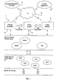
- a work flow manager 1 of a gateway comprises a process automation component 2, a policy engine 3, and a traffic gateway 4.
- the work flow manager 1 communicates via the internet 5 over IP with content providers 6 and content aggregators 7. On the other side it communicates over the Internet or over a private IP network, using diverse proprietary and known protocols with service enabler resources 20 including mobile network SMSCs, MMSCs and IMSs (IP Multi-Media Sub-systems). These in turn communicate over the internal communication mechanisms of the mobile network infrastructure with mobile network traffic elements 21 including BTSs, HLRs, MSCs and VLKs. The elements 21 in turn communicate with the mobile devices 22 via the BTSs.
- This diagram therefore illustrates the overall context of the work flow manager.
- the process automation component 2 presents a 'human friendly' tool such as a GUI to generate a work flow definition in a high level business process execution language (BPEL), with interaction with the service enabler resources 20 which implement the process.
- the policy engine 3 interprets the BPEL to provide lower-level policy enforcement work flows in a policy enforcement execution language (PEEL).
- the traffic gateway 4 interprets the PEEL to provide a low level language (traffic policy execution language, TPEL) for high performance implementation of steps of the work flow process.
- PRP means Policy Request Protocol, a lightweight protocol for AAA request/responses within the gateway 1.”
- SLA means service level agreement.
- the three components of the WFM 1 provide an intelligent bridge between the service provisioning side and the real time process implementation side. There is bi-directional communication across the three components in real time as a service is provided to a subscriber so that there is an optimum trade off at any point in time between performance and flexibility, as illustrated diagrammatically in Fig. 3 and described in more detail below.
- the workflow manager 1 is distributed across the process automation, the policy engine, and the traffic gateway.
- BPEL - Business Process Execution Language
- PEEL Policy Engine Execution Language
- TPEL Traffic Proxy Execution Language
- AAA Authentication, Authorisation, Accounting.
- the process automation component 2 interfaces with operators and defines according to operator inputs required work flows.
- the traffic gateway 4 manages execution of traffic flow for delivery of content.
- the policy engine 3 interfaces with the process automation component and with the traffic gateway.
- Each of the process automation component, the policy engine, and the traffic execute workflow instance referred to below as "BPEL workflows", “PEEL workflows”, and “TPEL workflows” or simple “BPEL”, "PEEL”, and “TPEL”.
- the policy engine workflow instances act as decision points, and the process automation component workflow instances and the traffic gateway workflow instances act as enforcement points.
- the decision point workflow instances execute work flow rules to determines compliance of work flows with a service level agreement and generate responses to requests from the enforcement point workflow instances.
- the policy engine has an interface for access to a stored mark-up language service level agreement representation. This is illustrated in Fig. 12 , access being via an optimised view of the SLA.
- the process automation component 2 can communicate with policy engine 3. i.e. the BPEL workflow includes a step which requires AAA from the policy engine 3. Thus BPEL workflow can invoke PEEL workflow.
- the traffic gateway 4 can communicate with the policy engine 3. i.e. the TPEL workflow includes a step which requires AAA from the policy engine. Thus TPEL workflow can invoke a PEEL workflow.
- the process automation and the traffic gateway do not interact. i.e., whilst the process of provisioning a service on the gateway is defined in BPEL and executed via the process automation component, once the service is provisioned, traffic goes through the traffic gateway 4.
- TPEL is not automatically created from PEEL. Further, there are no dependencies between BPEL, PEEL, and TPEL - they each define workflows within specific parts of the gateway in a mechanism which is most suited to the performance/flexibility characteristics of the data being processed by that part of the gateway.
- BPEL provides high flexibility on process automation, invoking business logic handlers to perform tasks in the process, and using a PRP Client (which can be considered a business logic handler for the policy engine) to perform AAA operations when the workflow definition for a given process demands it.
- PRP Client which can be considered a business logic handler for the policy engine
- TPEL provides high performance on traffic workflows, invoking protocol handlers to send and receive data, and the PRP client to perform AAA operations when the workflow definition for a given traffic, channel demands it.
- PEEL provides high performance on policy decision requests. The individual requests are handled by policies dedicated to management and traffic operations. Effectively, the policy handlers are the equivalent to the business logic handlers invoked by the BPEL, or traffic protocol handlers invoked by the TPEL.
- Compilation to actual machine code would mean having to build libraries and link them into the service. This is a relatively time consuming task to do on a live system handling large volumes of transactions per second, and prior systems may even mean bringing services off-line until they are reloaded with additional library and configuration data.
- the approach the invention has taken is to have the benefit of near low-level execution combined with already-optimised code.
- This object structure is then processed by an already-optimised engine - capable of handling any dynamically built object structure with the same degree of flexibility and performance.
- the transformation takes only a small fraction of the time required of compilation.
- the resulting object structure is immediately available for use, there being no need to bring the service offline.
- the engine which processes the object structure has already been optimised and is fully capable of performance and flexibility over any resulting object structure.
- Fig. 13 is a diagram ot a resulting Object structure.
- the engine There is an entry point for the engine to begin processing in terms of the Content Provider Hash Table (the term "table" does not imply a database table).
- Each entry in this hash table will have a random-access set of protocol objects, which the engine will process as required by the current traffic protocol.
- Each protocol object will point to an entry in a protocol usage rate hash table in the figure, that means 3 objects pointing to SMS, MMS and WS.
- a protocol usage rate hash table in the figure, that means 3 objects pointing to SMS, MMS and WS.
- SMS message The engine will have immediate access to the SMS protocol object, from which it can immediately access the correct entry in the SMS Protocol Usage Rate table (again, not a database table).
- the engine will then invoke a throttling method on the SMS Protocol Usage Rate entry object (this is why we have actual objects with invocable methods, rather than simply "dumb" database tables holding data) to determine if the SMS message exceeds per-second throttling.
- These objects extend classes defined in the engine, and the graph of connected object structures are thus data-driven embodiments of the engine.
- the SMS Protocol Usage Rate entry object will automatically invoke an increment method on the Content Provider's Usage Rate table, which will in turn automatically invoke an increment method on the daily transaction rate accumulator table. Should any of these increment methods exceed the maximum usage rate, the increment method will fail, and the engine will be aware that the current SMS traffic message has breached policy as defined in the SLA.
- this is an example which is deliberately simple, but the engine is capable of improving performance through parallelism. If the transformation determines that multiple checks can be made in parallel, then this will be carried out to improve throughput and reduce latency on policy decisions.
- the diagram of Fig. 5 shows the policy engine 3 making two level I decisions in parallel.
- the first level I decision requires a single level II decision to resolve.
- the second level I decision (which will be processed in parallel with the first) has itself two parallel decisions to be made at level II - the second of which has a level III decision to resolve.
- This diagram highlights how the police engine 3 can provide parallelism across arbitrary object structures (since the number of parallel tasks and the depth of decision points is arbitrary).
- Process Automation AAA Authentication, Authorising and Accounting
- policies require maximum flexibility to deal with privileged users performing high level operations, which may have multiple component lower-level operations, against complex data structures.
- the policy engine 3 is capable of making decisions and enforcing policy across multiple levels of functionality, and ensuring data access restrictions are enforced.
- the AAA requests associated with this Process can be defined independently of the SLA. For example, each task can have an AAA request associated with it, or the Process as a whole can have an AAA request associated with it - or only key data-sensitive tasks can have an AAA request associated with them.
- This decision can be made on a per-Process basis, so processes affecting critical or sensitive data can have additional checks made as appropriate. This is shown in Fig. 7 .
- the gateway 1 has separated the definition of the SLA privilege from the definition of the process automation policy decision points. However, there is also scope for the SLA to dictate which degree of checks need to be performed (i.e. establishing a level of trust within the SLA).
- gateway 1 Each of these individual tasks may operate on different data within gateway 1's flexible data model.
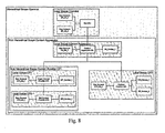
- This data model is not flat - it is a hierarchy, and therefore the policy engine must be capable of making decisions about data access anywhere within the hierarchy. This is shown in Fig. 8 .
- Gateway 1 may allow OP_UA_1 read/write access to the entire data model hierarchy, whilst OP_UA_2 may only have read access to the entire hierarchy.
- the gateway 1 may allow Content Aggregator's User Account CA_UA_1 to access the Content Aggregator's own Service (CA_Service_1), but limit CA_UA_1 to manipulating his child Content Providers (CP1, CP2) - but not their Services.
- CA_Service_1 Content Aggregator's User Account
- CP1, CP2 Content Aggregator's own Service
- CA_UA_1 User Account CP3_UA_1 cannot access any data outside of Local Scope CP3.
- the policy engine 3 is configured with a number of PEEL workflow definitions.
- the policy engine 3 can determine lower-level actions to implement a main action (by invoking various management or traffic policy operations defined in the PEEL WF). It uses a cascading privilege manager to support policy decisions across multiple levels of a hierarchy.
- the cascading privilege definition allows the policy engine to make decisions about delegated privileges defined in the SLA (i.e. privileges which are inherited by virtue of an entity's position in the data model hierarchy). If the policy engine 3 determines that a particular action can not be invoked as requested either by a BPEL WF or TPEL WF policy decision request task, then the policy decision request will be rejected with an indication of the nature of the rejection.
- the policy engine provides generic support for the configurable handling of the (above mentioned) policies on a per service and per service provider basis through a (Web Service Based) GUI enacting on an underlying rule based policy management engine. It represents a multi dimensional hierarchy of actors and privileges - which is then mapped into a single dimension for management. It provides the ability to develop configurable orchestrations of policy enforcements across the network enablers which cause the service enablers to perform differently according to the service or service enabler accessing them - without having to provide isolated service enabler environments for each service or service enabler.
- the policy engine is able to analyse QoS and provide SLA reporting without impact on the traffic using 'echoing' or 'wiretapping' at the traffic gateway level and non-intrusive monitoring at the policy engine level. This relates/integrates with the configurable type checking in the traffic gateways.
- the policy engine provides access to diverse 3 rd party legacy and proprietary systems and protocols through protocol adaptors, and the ability to extract and implement policy management criteria from such adaptors.
- the policy engine can use 3 rd party systems - whether that be as data sources for input to the policy making decision, or by delegating authority on making the decision (perhaps using input gathered from The gateway 1 and/or other 3 rd party systems) to one or more external policy decision points.
- the policy engine's work flow manager performs workflow automation and configurable logging to provide highly customisable, event driven SLA (Policy) and QoS monitoring. It uses workflow automation using Web Service and proprietary protocols and methods to build automated sequences (chains) of operations across diverse and disjoint underlying (telecoms, non-Web services) systems and platforms.
- Another aspect of the policy engine is it's facility to provide an atomic part or parts of the operation sequence of a service either by providing a mechanism to access the service or by providing controlled access to that service through the gateway 1 - with or without the knowledge of the service provider (i.e. the developer of the end service)
- PEEL is used where the real time workflow automation is provided in a form which uses the data format similar to that provided by BPEL, but is implemented in such a way that no central decoding of the data needs to be performed, but where an interpretation mechanism is available to each decoding entity through which results in a high performance configurable workflow mechanism.
- the policy engine contains optimised rules for different types of traffic and management operations. The structure of the policy engine is shown in Fig. 10 .
- Media-rich content may include additional rules for enforcing MIME type limitations - something which is not necessary on plain text payloads like SMS texts.
- the PEEL workflow is selected by the PRP Server using information contained in the PRP request.
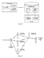
- Fig. 11 shows sample rule workflows in the policy engine. Any part of a rule can be bypassed if a cached entry is present. For example, since Authentication details are the same for the same application making requests across different traffic protocols, the Authentication details can be cached in the PRP Client, and an Authenticated Token can be supplied, which means the policy engine does not attempt to re-authenticate.
- a policy engine data store supports optimised views of the SLA.
- Fig. 12 shows policy engine views on the data store.
- the Traffic Optimised View of the SLA is automatically created when the SLA is updated. For example, consider an SLA clause which dictates the following limitations on a content provider's applications:
- the SLA would be defined in XML, for example:
- Fig. 13 show optimised traffic model for a sample SLA.
- the technology allows any type of table to be linked to the content provider hash table, with the type of table(s) being defined within the SLA (because the tables are created by performing a translation on the SLA).
- the SLA is defined on a per-Content Provider basis, different Content Providers can have different links to different types of tables.
- dependency links can be created to model clauses that need to be processed by the engine.
- the list is automatically generated by transformation of the SLA defined for a given ContentProvider.
- Each table has a counter which is incremented for every occurrence of a parameter. This is dependent on the SLA clause.
- Some clauses may result in a counter being created. Others may result in a rangeOperator method being created. For example, a Billing Clause may have a min/max charge amount - so the object structure would create a rangeCheck method that determines if the cost of the message lies between the allowed charge range.
- the usage table for the protocol defined for the content provider that owns the application is updated - with throttling limits applied. Maximum throughput and daily usage limits are also automatically applied. Only if all entries in the chain (modelling all clauses in the SLA which are applicable to the application) pass shall the policy engine allow the traffic to proceed. But there is no need to process the SLA on a per-message basis - in fact, the SLA has been used to dynamically create a data structure whose natural form and function is to enable highly performant rules-based checking of run-time traffic.
- the traffic gateway is mainly configured to implement a work flow in real time for transactions. It is configured for traffic message channels using a low-level highperformance TPEL language.
- pass-through There are two main categories of transaction to be handled, "pass-through” and “convergent”. For pass-through transactions there is minimal interaction with the engine 3, only direct implementation with high performance of a relatively simple work flow series of actions.
- An example is in cases where Multimedia Messaging services are provided in native MM7 format. In this case service related traffic will be provided directly to the Traffic Proxies in the MM7 format, and no decoding or translation of the data is required for transmission to the destination device.
- the policy enforcement will be provided by monitoring the data stream provided in MM7 format, through the use of low-level TPEL operations which use an inherent knowledge of the MM7 packet formats to implement low level policy enforcement.
- policy enforcement components can be deployed within the traffic engine and be invoked by TPEL operations where it is suitable to do so (i.e. where the policy decision can be made entirely using the current message without further context).
- policy enforcement needs to be made in conjunction with context e.g. historical usage patterns to determine transaction rates
- TPEL will use PRP to have the Policy Engine make the request with full contextual knowledge of the application and/or content provider's recent traffic usage (where the window of retainment of contextual information is defined in the SLA and represented in the object structure - e.g. transactions per second, max transactions per hour).
- a Service Workflow may define the services as a sequence of operations using multiple Service Enablers and Multiple Service Data Formats - for example using a specifically formatted Mobile Originated Short.
- Message containing a specific text keyword to indicate to an Application the data required for download.
- the service data may be supplied from the application server in an internet format, for example in the form of gif file, but may require delivery in SMIL format over MMS.
- the mapping of the data coming through the traffic gateways to the specific data feeds and formats required can only be carried out through interaction of the policy engine.
- the traffic gateway provides the ability to provide configurable type checking across the network enablers which cause the service enablers to perform differently according to the service or service enabler accessing them - without having to provide isolated service enabler environments for each service or service enabler. It also executes real-time workflows for highly performant-type checking. These workflows are configured for the various message channels on The gateway 1, allowing different message channels to have their own optimised workflows.
- Traffic Gateway AAA requests require maximum performance to deal with privileged users performing large volumes of messages demanding low latency through the platform. Such traffic will have various constraints in terms of transactions per unit time, maximum transactions per unit time etc.
- a single traffic gateway may not be capable of handling all traffic belonging to a single content provider - yet the SLA may define traffic restrictions across multiple protocols across multiple applications belonging to a single content provider.
- the scalable deployment model of the traffic proxies and policy engines must support the ability to allow policy decisions to be made for multiple traffic proxies, optimised for different message channels. This is shown in Fig. 9 .
Landscapes
- Engineering & Computer Science (AREA)
- Computer Networks & Wireless Communication (AREA)
- Signal Processing (AREA)
- Data Exchanges In Wide-Area Networks (AREA)
- Massaging Devices (AREA)
- Mobile Radio Communication Systems (AREA)
Abstract
Description
- The invention relates to a gateway for interfacing between the content/service provider domain and communication networks such as mobile networks.
- Our prior PCT Specification No.
WO2004/036855 - The invention is directed towards achieving improved work flow management in such a gateway, both in terms of flexibility and real time performance.
- According to the invention, there is provided gateway as set out in
claim 1, for interfacing between content provider servers and a communication network for delivery of content to user devices. - In one embodiment, the policy engine comprises an interface for access to a stored mark-up language service level agreement representation.
- In one embodiment, the process automation component generates a human-readable operator-level model of desired content routing work flows, and allows dynamic operator-driven modification of said work flow.
- In another embodiment, the process automation component automatically defines said desired work flows independently of the service level agreement
- In one embodiment, each request is an authentication, authorising and accounting request.
- In one embodiment, the process automation component workflow instances generate:
- for some work flow processes only a single policy enforcement point request to initiate said processes,
- for some work flow processes a policy enforcement point request for every process task, and
- for some work flow processes a policy enforcement point request for only key process tasks, and
- for some work flow processes a conditional policy enforcement point request for some or all process tasks.
- In one embodiment, the process tasks operate with process data at different levels within a process data model for the desired work flows.
- In a further embodiment, the process data model incorporates branches for different content provider servers.
- In one embodiment, each branch includes process data permissions governing read-only or write-enabled access to content on per-user and per-content provider server basis.
- In one embodiment, there is a link between protocol objects for SMS communication, a link for MMS communication, and a link for WS communication.
- In one embodiment, protocol objects at the end of a chain automatically compute data according to entries to the tables in the chain.
- In one embodiment, the traffic gateway comprises a traffic policy sub-cluster for each of a plurality of traffic protocols.
- In one embodiment, each policy sub-cluster receives requests from the policy engine, and generates responses.
- In one embodiment, each sub-cluster communicates with a traffic load balancer, which in turn routes traffic onto the mobile network or a content provider server network.
- The invention will be more clearly understood from the following description of some embodiments thereof, given by way of example only with reference to the accompanying drawings in which:-
-
Fig. 1 is a block diagram showing the major work flow management components of a gateway of the invention and its environment; -
Fig. 2 is a diagram showing a work flow manager of the gateway in more detail, andFig. 3 is a diagram showing the requirements at different levels of the manager, -
Fig. 4 is a message flow diagram for SMS traffic handled by the gateway; -
Fig. 5 is a diagram showing parallel decision making in the work flow manager; -
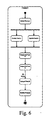
Fig. 6 is a diagram showing constituent parallel, sequential, and delayed tasks; -
Fig. 7 shows different policy enforcement points; -
Fig. 8 shows a hierarchical data model for the work flow manager; -
Fig. 9 is a diagram illustrating policy decisions across multiple traffic protocols across multiple applications; -
Fig. 10 is a diagram showing a policy decision node; -
Fig. 11 is a pair of flow diagrams showing sample rule workflows in a policy engine of the work flow manager; -
Fig. 12 is a diagram showing interconnection between a policy engine and its data store; -
Fig. 13 is a diagram showing interconnection of rate tables for work flow management; and -
Fig 14 is a diagram showing conditional policy enforcement checks within a workflow, which interact with a Service Level Agreement establishing a level of trust, to provide dynamic degrees of policy enforcement for the same workflow. - Referring to
Fig. 1 awork flow manager 1 of a gateway comprises aprocess automation component 2, apolicy engine 3, and atraffic gateway 4. Thework flow manager 1 communicates via theinternet 5 over IP withcontent providers 6 and content aggregators 7. On the other side it communicates over the Internet or over a private IP network, using diverse proprietary and known protocols withservice enabler resources 20 including mobile network SMSCs, MMSCs and IMSs (IP Multi-Media Sub-systems). These in turn communicate over the internal communication mechanisms of the mobile network infrastructure with mobilenetwork traffic elements 21 including BTSs, HLRs, MSCs and VLKs. Theelements 21 in turn communicate with themobile devices 22 via the BTSs. - This diagram therefore illustrates the overall context of the work flow manager. There is a "three dimensional aspect to traffic management for providing content or services to mobile devices, namely content, mobile network, and real time work flow management.
- Referring to
Figs. 2 and 3 the following are the primary roles of the components. Theprocess automation component 2 presents a 'human friendly' tool such as a GUI to generate a work flow definition in a high level business process execution language (BPEL), with interaction with theservice enabler resources 20 which implement the process. Thepolicy engine 3 interprets the BPEL to provide lower-level policy enforcement work flows in a policy enforcement execution language (PEEL). Thetraffic gateway 4 interprets the PEEL to provide a low level language (traffic policy execution language, TPEL) for high performance implementation of steps of the work flow process. PRP means Policy Request Protocol, a lightweight protocol for AAA request/responses within the gateway 1."SLA" means service level agreement. - Thus, the three components of the WFM 1 provide an intelligent bridge between the service provisioning side and the real time process implementation side. There is bi-directional communication across the three components in real time as a service is provided to a subscriber so that there is an optimum trade off at any point in time between performance and flexibility, as illustrated diagrammatically in
Fig. 3 and described in more detail below. - The
workflow manager 1 is distributed across the process automation, the policy engine, and the traffic gateway. BPEL - (Business Process Execution Language) is a high level, highly flexible workflow language. PEEL (Policy Engine Execution Language) is a. mid-level, high performance, good flexibility workflow language. TPEL (Traffic Proxy Execution Language) is a. low-level, highly performant workflow language. The term "AAA" means Authentication, Authorisation, Accounting. - The
process automation component 2 interfaces with operators and defines according to operator inputs required work flows. Thetraffic gateway 4 manages execution of traffic flow for delivery of content. Thepolicy engine 3 interfaces with the process automation component and with the traffic gateway. Each of the process automation component, the policy engine, and the traffic execute workflow instance, referred to below as "BPEL workflows", "PEEL workflows", and "TPEL workflows" or simple "BPEL", "PEEL", and "TPEL". The policy engine workflow instances act as decision points, and the process automation component workflow instances and the traffic gateway workflow instances act as enforcement points. The decision point workflow instances execute work flow rules to determines compliance of work flows with a service level agreement and generate responses to requests from the enforcement point workflow instances. The policy engine has an interface for access to a stored mark-up language service level agreement representation. This is illustrated inFig. 12 , access being via an optimised view of the SLA. - The three languages are decoupled, without compiling from one to the other. The
process automation component 2 can communicate withpolicy engine 3. i.e. the BPEL workflow includes a step which requires AAA from thepolicy engine 3. Thus BPEL workflow can invoke PEEL workflow. Thetraffic gateway 4 can communicate with thepolicy engine 3. i.e. the TPEL workflow includes a step which requires AAA from the policy engine. Thus TPEL workflow can invoke a PEEL workflow. The process automation and the traffic gateway do not interact. i.e., whilst the process of provisioning a service on the gateway is defined in BPEL and executed via the process automation component, once the service is provisioned, traffic goes through thetraffic gateway 4. - No one language is compiled into a lower language form. For example, TPEL is not automatically created from PEEL. Further, there are no dependencies between BPEL, PEEL, and TPEL - they each define workflows within specific parts of the gateway in a mechanism which is most suited to the performance/flexibility characteristics of the data being processed by that part of the gateway.
- Referring again to
Fig. 2 , BPEL provides high flexibility on process automation, invoking business logic handlers to perform tasks in the process, and using a PRP Client (which can be considered a business logic handler for the policy engine) to perform AAA operations when the workflow definition for a given process demands it. TPEL provides high performance on traffic workflows, invoking protocol handlers to send and receive data, and the PRP client to perform AAA operations when the workflow definition for a given traffic, channel demands it. PEEL provides high performance on policy decision requests. The individual requests are handled by policies dedicated to management and traffic operations. Effectively, the policy handlers are the equivalent to the business logic handlers invoked by the BPEL, or traffic protocol handlers invoked by the TPEL. - Compilation to actual machine code would mean having to build libraries and link them into the service. This is a relatively time consuming task to do on a live system handling large volumes of transactions per second, and prior systems may even mean bringing services off-line until they are reloaded with additional library and configuration data.
- Alternative methods are to compile to something short of actual machine code - which is then run on a virtual machine. This is still a relatively time consuming task, still needs optimisation of the resulting byte code. It does however negate any requirements on restarting the service.
- However, the approach the invention has taken is to have the benefit of near low-level execution combined with already-optimised code. Instead of compiling one language into a lower level language, we transform the high level language into a low level object structure who's natural form and function provides for the required degree of flexibility and performance. This object structure is then processed by an already-optimised engine - capable of handling any dynamically built object structure with the same degree of flexibility and performance.
- Advantageously, the transformation takes only a small fraction of the time required of compilation. The resulting object structure is immediately available for use, there being no need to bring the service offline. The engine which processes the object structure has already been optimised and is fully capable of performance and flexibility over any resulting object structure.
- Consider
Fig. 13 , which is a diagram ot a resulting Object structure. There is an entry point for the engine to begin processing in terms of the Content Provider Hash Table (the term "table" does not imply a database table). Each entry in this hash table will have a random-access set of protocol objects, which the engine will process as required by the current traffic protocol. Each protocol object will point to an entry in a protocol usage rate hash table in the figure, that means 3 objects pointing to SMS, MMS and WS. Suppose we have an SMS message. The engine will have immediate access to the SMS protocol object, from which it can immediately access the correct entry in the SMS Protocol Usage Rate table (again, not a database table). The engine will then invoke a throttling method on the SMS Protocol Usage Rate entry object (this is why we have actual objects with invocable methods, rather than simply "dumb" database tables holding data) to determine if the SMS message exceeds per-second throttling. These objects extend classes defined in the engine, and the graph of connected object structures are thus data-driven embodiments of the engine. The SMS Protocol Usage Rate entry object will automatically invoke an increment method on the Content Provider's Usage Rate table, which will in turn automatically invoke an increment method on the daily transaction rate accumulator table. Should any of these increment methods exceed the maximum usage rate, the increment method will fail, and the engine will be aware that the current SMS traffic message has breached policy as defined in the SLA. - Referring to
Fig. 4 , this is an example which is deliberately simple, but the engine is capable of improving performance through parallelism. If the transformation determines that multiple checks can be made in parallel, then this will be carried out to improve throughput and reduce latency on policy decisions. - The diagram of
Fig. 5 shows thepolicy engine 3 making two level I decisions in parallel. The first level I decision requires a single level II decision to resolve. The second level I decision (which will be processed in parallel with the first) has itself two parallel decisions to be made at level II - the second of which has a level III decision to resolve. This diagram highlights how thepolice engine 3 can provide parallelism across arbitrary object structures (since the number of parallel tasks and the depth of decision points is arbitrary). - Process Automation AAA (Authentication, Authorising and Accounting) requests require maximum flexibility to deal with privileged users performing high level operations, which may have multiple component lower-level operations, against complex data structures. Thus the
policy engine 3 is capable of making decisions and enforcing policy across multiple levels of functionality, and ensuring data access restrictions are enforced. - This task is further complicated by the fact that a Service Level Agreement provides a user-defined view of the available processes. It does not provide a system level view. Further, even if conventional methods of solving this problem (namely having a system level view - perhaps hidden - within the SLA) are employed, it does not offer the flexibility which the
gateway 1 provides - because thegateway 1 is capable of hosting dynamically defined business processes - thus the SLA would become dynamic, making it impossible to have two-way non-repudiation of the SLA (since it too would be constantly in a state of flux).
Consider the process ofFigs. 6 and7 - Process X. The SLA would indicate whether or not a user is allowed to invoke Process X. However, because Process X is actually composed of 5 discrete tasks (and could be subject to change in the future should additional tasks be added to the process), the policy engine must be able to flexibly control the constituent tasks. - The AAA requests associated with this Process to be defined independently of the SLA. For example, each task can have an AAA request associated with it, or the Process as a whole can have an AAA request associated with it - or only key data-sensitive tasks can have an AAA request associated with them. This decision can be made on a per-Process basis, so processes affecting critical or sensitive data can have additional checks made as appropriate. This is shown in
Fig. 7 . Thegateway 1 has separated the definition of the SLA privilege from the definition of the process automation policy decision points. However, there is also scope for the SLA to dictate which degree of checks need to be performed (i.e. establishing a level of trust within the SLA). For example, referring toFig 14 , there is the flexibility to define conditional policy checks, and allow the SLA to establish a degree of trust - trusted users need only be subject to key policy enforcement checks, whilst untrusted users may be subjected to all checks. - Each of these individual tasks may operate on different data within
gateway 1's flexible data model. This data model is not flat - it is a hierarchy, and therefore the policy engine must be capable of making decisions about data access anywhere within the hierarchy. This is shown inFig. 8 . - Suppose User Account OP_UA_1 is an Administrator, and User Account OP_UA_2 is a Customer Care Agent. Then
Gateway 1 may allow OP_UA_1 read/write access to the entire data model hierarchy, whilst OP_UA_2 may only have read access to the entire hierarchy. - The
gateway 1 may allow Content Aggregator's User Account CA_UA_1 to access the Content Aggregator's own Service (CA_Service_1), but limit CA_UA_1 to manipulating his child Content Providers (CP1, CP2) - but not their Services.
As another example, User Account CP3_UA_1 cannot access any data outside of Local Scope CP3. - The
policy engine 3 is configured with a number of PEEL workflow definitions. Thepolicy engine 3 can determine lower-level actions to implement a main action (by invoking various management or traffic policy operations defined in the PEEL WF). It uses a cascading privilege manager to support policy decisions across multiple levels of a hierarchy. The cascading privilege definition allows the policy engine to make decisions about delegated privileges defined in the SLA (i.e. privileges which are inherited by virtue of an entity's position in the data model hierarchy). If thepolicy engine 3 determines that a particular action can not be invoked as requested either by a BPEL WF or TPEL WF policy decision request task, then the policy decision request will be rejected with an indication of the nature of the rejection. - The policy engine provides generic support for the configurable handling of the (above mentioned) policies on a per service and per service provider basis through a (Web Service Based) GUI enacting on an underlying rule based policy management engine. It represents a multi dimensional hierarchy of actors and privileges - which is then mapped into a single dimension for management. It provides the ability to develop configurable orchestrations of policy enforcements across the network enablers which cause the service enablers to perform differently according to the service or service enabler accessing them - without having to provide isolated service enabler environments for each service or service enabler.
- The policy engine is able to analyse QoS and provide SLA reporting without impact on the traffic using 'echoing' or 'wiretapping' at the traffic gateway level and non-intrusive monitoring at the policy engine level. This relates/integrates with the configurable type checking in the traffic gateways.
- The policy engine provides access to diverse 3rd party legacy and proprietary systems and protocols through protocol adaptors, and the ability to extract and implement policy management criteria from such adaptors. Thus the policy engine can use 3rd party systems - whether that be as data sources for input to the policy making decision, or by delegating authority on making the decision (perhaps using input gathered from The
gateway 1 and/or other 3rd party systems) to one or more external policy decision points. - The policy engine's work flow manager performs workflow automation and configurable logging to provide highly customisable, event driven SLA (Policy) and QoS monitoring. It uses workflow automation using Web Service and proprietary protocols and methods to build automated sequences (chains) of operations across diverse and disjoint underlying (telecoms, non-Web services) systems and platforms.
- Another aspect of the policy engine is it's facility to provide an atomic part or parts of the operation sequence of a service either by providing a mechanism to access the service or by providing controlled access to that service through the gateway 1 - with or without the knowledge of the service provider (i.e. the developer of the end service)
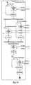
- PEEL is used where the real time workflow automation is provided in a form which uses the data format similar to that provided by BPEL, but is implemented in such a way that no central decoding of the data needs to be performed, but where an interpretation mechanism is available to each decoding entity through which results in a high performance configurable workflow mechanism. The policy engine contains optimised rules for different types of traffic and management operations. The structure of the policy engine is shown in
Fig. 10 . - Media-rich content may include additional rules for enforcing MIME type limitations - something which is not necessary on plain text payloads like SMS texts.
- The PEEL workflow is selected by the PRP Server using information contained in the PRP request.
-
Fig. 11 shows sample rule workflows in the policy engine. Any part of a rule can be bypassed if a cached entry is present. For example, since Authentication details are the same for the same application making requests across different traffic protocols, the Authentication details can be cached in the PRP Client, and an Authenticated Token can be supplied, which means the policy engine does not attempt to re-authenticate. - There is caching of components within a policy engine workflow as well as the BPEL workflow and TPEL workflow - providing a highly performant cache hierarchy.
- To address the different needs of management and run-time traffic performance from a single data source, a policy engine data store supports optimised views of the SLA.
Fig. 12 shows policy engine views on the data store. - The Traffic Optimised View of the SLA is automatically created when the SLA is updated. For example, consider an SLA clause which dictates the following limitations on a content provider's applications:
- SMS Applications have a maximum summation of 50 TPS
- MMS Applications have a maximum summation of 20 TPS
- Web Service Applications have a maximum summation of 100 TPS
- The Content Provider has a maximum throughput of 125 TPS across all active applications
- The Content Provider has a maximum daily throughput of 10,000 transactions across all active applications.
- The SLA would be defined in XML, for example:
 <Sla>
  <ContentProvider> uuid-12345-67890 </ContentProvider>
  <ApplicationClauses>
    <Clause>
       <Type> Sms </Type>
       <MaxRate> 50 </MaxRate>
    </Clause>
    <Clause>
      <Type> Mms </Type>
      <MaxRate> 20 </MaxRate>
    </Clause>
    <Clause>
      <Type> WebService </Type>
      <MaxRate> 100 </MaxRate>
    </Clause>
  </ApplicationClauses>
  <ProviderClauses>
    <Clause>
      <Type> Throughput </Type>
      <Value> 125 </Value>
    </Clause>
    <Clause>
     <Type> DailyLimit </Type>
      <Value> 10000 </Value>
    </Clause>
  </ProviderGlauses>
 </Sla>
Claims (15)
- A gateway for interfacing between content provider servers and a communication network for delivery of content to user devices, the gateway comprising a work flow manager comprising:a process automation component for interfacing with operators and defining according to operator inputs required work flows;a traffic gateway for managing execution of traffic flow for delivery of content;a policy engine for interfacing with the process automation component and with the traffic gateway;wherein each of the process automation component, the policy engine, and the traffic gateway execute workflow instances; and
wherein the policy engine workflow instances act as decision points, and the process automation component workflow instances and the traffic gateway workflow instances act as enforcement points; and
wherein the policy engine comprises:policy decision nodes, each having a traffic policy, a management policy, and a decision server,traffic nodes communicating with the decision servers,management nodes communicating with the decision servers; andwherein the management nodes access an operator-level workflow model and the traffic nodes access a traffic-optimised work flow model;
characterized by :
wherein the policy engine decision point workflow instances execute work flow rules to determine compliance of work flows with a service level agreement (SLA) and generate responses to requests from the enforcement point workflow instances, and the process automation component and traffic gateway workflow instances can invoke policy engine workflow instances, the traffic-optimised workflow model comprises a content provider hash table, each entry in said table having a random-access set of protocol objects which the policy engine will process as required by a current traffic protocol, said protocol objects point to protocol usage rate objects, the protocol usage rate objects invoking increment methods on content provider usage rate objects, and
wherein the policy engine recognises that traffic exceeds an SLA if any of the invoked increment methods exceed a maximum usage rate. - A gateway as claimed in claim 1, wherein the policy engine comprises an interface for access to a stored mark-up language service level agreement representation.
- A gateway as claimed in any preceding claim, wherein the process automation component generates a human-readable operator-level model of desired content routing work flows, and allows dynamic operator-driven modification of said work flow.
- A gateway as claimed in claim 3, wherein the process automation component automatically defines said desired work flows independently of the service level agreement.
- A gateway as claimed in any of claims 1 to 4, wherein each request is an authentication, authorising and accounting request.
- A gateway as claimed in any preceding claim, wherein the process automation component workflow instances generate:for some work flow processes only a single policy enforcement point request to initiate said processes,for some work flow processes a policy enforcement point request for every process task, andfor some work flow processes a policy enforcement point request for only key process tasks, andfor some work flow processes a conditional policy enforcement point request for some or all process tasks.
- A gateway as claimed in claim 6, wherein the process tasks operate with process data at different levels within a process data model for the desired work flows.
- A gateway as claimed in claim 7, wherein the process data model incorporates branches for different content provider servers.
- A gateway as claimed in claim 8, wherein each branch includes process data permissions governing read-only or write-enabled access to content on per-user and per-content provider server basis.
- A gateway as claimed in any preceding claim, wherein there is a link between protocol objects for SMS communication, for MMS communication, and for WS communication.
- A gateway as claimed in any preceding claim, wherein protocol objects at the end of a chain automatically compute data according to entries to the tables iri the chain.
- A gateway as claimed in any preceding claim, wherein the traffic gateway comprises a traffic policy sub-cluster for each of a plurality of traffic protocols.
- A gateway as claimed in claim 12, wherein each policy sub-cluster receives requests from the policy engine, and generates responses.
- A gateway as claimed in claims 12 or 13, wherein each sub-cluster communicates with a traffic load balancer, which in turn routes traffic onto the mobile network or a content provider server network.
- A computer program product comprising software code for performing work flow manager operations of a gateway of any preceding claim when executing on a digital data processor.
Applications Claiming Priority (2)
| Application Number | Priority Date | Filing Date | Title |
|---|---|---|---|
| US63774204P | 2004-12-22 | 2004-12-22 | |
| PCT/IE2005/000148 WO2006067776A1 (en) | 2004-12-22 | 2005-12-22 | A gateway |
Publications (2)
| Publication Number | Publication Date |
|---|---|
| EP1836816A1 EP1836816A1 (en) | 2007-09-26 |
| EP1836816B1 true EP1836816B1 (en) | 2009-09-16 |
Family
ID=35976668
Family Applications (1)
| Application Number | Title | Priority Date | Filing Date |
|---|---|---|---|
| EP05819831A Expired - Lifetime EP1836816B1 (en) | 2004-12-22 | 2005-12-22 | A gateway |
Country Status (5)
| Country | Link |
|---|---|
| US (1) | US7844741B2 (en) |
| EP (1) | EP1836816B1 (en) |
| AT (1) | ATE443397T1 (en) |
| DE (1) | DE602005016723D1 (en) |
| WO (1) | WO2006067776A1 (en) |
Families Citing this family (35)
| Publication number | Priority date | Publication date | Assignee | Title |
|---|---|---|---|---|
| US20080194208A1 (en) * | 1997-07-30 | 2008-08-14 | Steven Tischer | Apparatus, method, and computer-readable medium for communicating between and controlling network devices |
| US20080192768A1 (en) * | 1997-07-30 | 2008-08-14 | Steven Tischer | Apparatus, method, and computer-readable medium for interfacing communication devices |
| US20080207197A1 (en) * | 1997-07-30 | 2008-08-28 | Steven Tischer | Apparatus, method, and computer-readable medium for interfacing devices with communications networks |
| US20080194225A1 (en) * | 1997-07-30 | 2008-08-14 | Steven Tischer | Apparatus and method for providing emergency and alarm communications |
| US7149514B1 (en) | 1997-07-30 | 2006-12-12 | Bellsouth Intellectual Property Corp. | Cellular docking station |
| US8000682B2 (en) | 2002-07-15 | 2011-08-16 | At&T Intellectual Property I, L.P. | Apparatus and method for restricting access to data |
| US8275371B2 (en) | 2002-07-15 | 2012-09-25 | At&T Intellectual Property I, L.P. | Apparatus and method for providing communications and connection-oriented services to devices |
| US8526466B2 (en) | 2002-07-15 | 2013-09-03 | At&T Intellectual Property I, L.P. | Apparatus and method for prioritizing communications between devices |
| US8554187B2 (en) | 2002-07-15 | 2013-10-08 | At&T Intellectual Property I, L.P. | Apparatus and method for routing communications between networks and devices |
| US7200424B2 (en) | 2002-07-15 | 2007-04-03 | Bellsouth Intelectual Property Corporation | Systems and methods for restricting the use and movement of telephony devices |
| US8416804B2 (en) | 2002-07-15 | 2013-04-09 | At&T Intellectual Property I, L.P. | Apparatus and method for providing a user interface for facilitating communications between devices |
| US8543098B2 (en) | 2002-07-15 | 2013-09-24 | At&T Intellectual Property I, L.P. | Apparatus and method for securely providing communications between devices and networks |
| US8756521B1 (en) | 2004-09-30 | 2014-06-17 | Rockwell Automation Technologies, Inc. | Systems and methods for automatic visualization configuration |
| US7809683B2 (en) | 2005-05-13 | 2010-10-05 | Rockwell Automation Technologies, Inc. | Library that includes modifiable industrial automation objects |
| US7672737B2 (en) * | 2005-05-13 | 2010-03-02 | Rockwell Automation Technologies, Inc. | Hierarchically structured data model for utilization in industrial automation environments |
| US7650405B2 (en) | 2005-05-13 | 2010-01-19 | Rockwell Automation Technologies, Inc. | Tracking and tracing across process boundaries in an industrial automation environment |
| US7676281B2 (en) * | 2005-05-13 | 2010-03-09 | Rockwell Automation Technologies, Inc. | Distributed database in an industrial automation environment |
| US8799800B2 (en) | 2005-05-13 | 2014-08-05 | Rockwell Automation Technologies, Inc. | Automatic user interface generation |
| US8095688B2 (en) * | 2007-02-01 | 2012-01-10 | Oracle International Corporation | Staging latency performances and orchestrating network resources with low latency requirements |
| US8972518B2 (en) * | 2007-09-20 | 2015-03-03 | Flash Networks Ltd. | Integrated data-model and flow based policy system |
| US8054744B1 (en) * | 2007-10-25 | 2011-11-08 | Marvell International Ltd. | Methods and apparatus for flow classification and flow measurement |
| MX2009008285A (en) * | 2008-08-12 | 2010-05-17 | Bank Of America | Workflow automation & request processing. |
| US8126837B2 (en) * | 2008-09-23 | 2012-02-28 | Stollman Jeff | Methods and apparatus related to document processing based on a document type |
| US8464313B2 (en) * | 2008-11-10 | 2013-06-11 | Jeff STOLLMAN | Methods and apparatus related to transmission of confidential information to a relying entity |
| US8549589B2 (en) | 2008-11-10 | 2013-10-01 | Jeff STOLLMAN | Methods and apparatus for transacting with multiple domains based on a credential |
| US8930527B2 (en) * | 2009-05-26 | 2015-01-06 | Oracle International Corporation | High availability enabler |
| US8688816B2 (en) | 2009-11-19 | 2014-04-01 | Oracle International Corporation | High availability by letting application session processing occur independent of protocol servers |
| US8984533B2 (en) | 2010-04-15 | 2015-03-17 | Rockwell Automation Technologies, Inc. | Systems and methods for conducting communications among components of multidomain industrial automation system |
| US9392072B2 (en) | 2010-04-15 | 2016-07-12 | Rockwell Automation Technologies, Inc. | Systems and methods for conducting communications among components of multidomain industrial automation system |
| US8484401B2 (en) | 2010-04-15 | 2013-07-09 | Rockwell Automation Technologies, Inc. | Systems and methods for conducting communications among components of multidomain industrial automation system |
| US9652292B2 (en) * | 2011-08-03 | 2017-05-16 | Oracle International Corporation | System and method for business process gateway token flow |
| US11514423B1 (en) * | 2018-01-31 | 2022-11-29 | Wells Fargo Bank, N.A. | Systems and methods for a transactional keyboard |
| US10887240B2 (en) | 2018-02-26 | 2021-01-05 | Marvell Israel (M.I.S.L) Ltd. | Automatic flow learning in network devices |
| US11218411B2 (en) | 2019-11-21 | 2022-01-04 | Marvell Israel (M.I.S.L) Ltd. | Flow monitoring in network devices |
| CN120069772A (en) * | 2024-12-27 | 2025-05-30 | 海尔消费金融有限公司 | Intelligent wind control automatic approval system integrating FICO Blaze decision engine |
Family Cites Families (4)
| Publication number | Priority date | Publication date | Assignee | Title |
|---|---|---|---|---|
| US6754662B1 (en) * | 2000-08-01 | 2004-06-22 | Nortel Networks Limited | Method and apparatus for fast and consistent packet classification via efficient hash-caching |
| AU2003234202A1 (en) | 2002-04-23 | 2003-11-10 | Edgile, Inc. | System for managing and delivering digital services through computer networks |
| JP2006504297A (en) | 2002-10-16 | 2006-02-02 | モバイル・コヒージョン・リミテッド | Service access gateway |
| US7103351B2 (en) * | 2003-06-23 | 2006-09-05 | July Systems Inc. | Policy service system and methodology |
-
2005
- 2005-12-22 WO PCT/IE2005/000148 patent/WO2006067776A1/en not_active Ceased
- 2005-12-22 AT AT05819831T patent/ATE443397T1/en not_active IP Right Cessation
- 2005-12-22 DE DE602005016723T patent/DE602005016723D1/en not_active Expired - Lifetime
- 2005-12-22 EP EP05819831A patent/EP1836816B1/en not_active Expired - Lifetime
- 2005-12-22 US US11/793,419 patent/US7844741B2/en not_active Expired - Fee Related
Also Published As
| Publication number | Publication date |
|---|---|
| US20070268922A1 (en) | 2007-11-22 |
| EP1836816A1 (en) | 2007-09-26 |
| WO2006067776A1 (en) | 2006-06-29 |
| US7844741B2 (en) | 2010-11-30 |
| DE602005016723D1 (en) | 2009-10-29 |
| ATE443397T1 (en) | 2009-10-15 |
Similar Documents
| Publication | Publication Date | Title |
|---|---|---|
| US7844741B2 (en) | Gateway | |
| Chandramouli | Microservices-based application systems | |
| Chandramouli et al. | Building secure microservices-based applications using service-mesh architecture | |
| US11388200B2 (en) | Scalable network security detection and prevention platform | |
| US8856862B2 (en) | Message processing methods and systems | |
| US7739382B2 (en) | Dynamic extension of network-accessible services | |
| US20070283317A1 (en) | Inter domain services manager | |
| US20060130070A1 (en) | System and method of event correlation | |
| EP1419633B1 (en) | A secure gateway with proxy service capability servers for service level agreement checking | |
| US8365189B2 (en) | Method and apparatus for a service control layer | |
| JP2004532472A (en) | Service triggering framework | |
| Boumlik et al. | Security enforcement on web services compositions | |
| US12602470B1 (en) | Containerized execution of secure model context protocol servers for artificial intelligence agents | |
| Bellavista et al. | Mobile agents for Web‐based systems management | |
| Patel et al. | Binary Decision Tree Based Packet Queuing Schema for Next Generation Firewall | |
| Liu et al. | Active mediation technology for service composition | |
| Peters et al. | A holistic approach to security policies–policy distribution with xacml over cops | |
| Yamanaka et al. | A HORB-based network management system | |
| Robinson et al. | An aspect of application security management | |
| Zinky et al. | Experience with dynamic crosscutting in cougaar | |
| Lippert et al. | Security Analysis for the Middleware Assurance Substrate | |
| Pasternak et al. | Client-Server Interaction on the WWW | |
| Network et al. | Management System | |
| Mengusoglu et al. | Automated management and service provisioning model for distributed devices | |
| Lam et al. | Regulating Orchestration in SOA-Based Systems |
Legal Events
| Date | Code | Title | Description |
|---|---|---|---|
| PUAI | Public reference made under article 153(3) epc to a published international application that has entered the european phase |
Free format text: ORIGINAL CODE: 0009012 |
|
| 17P | Request for examination filed |
Effective date: 20070704 |
|
| AK | Designated contracting states |
Kind code of ref document: A1 Designated state(s): AT BE BG CH CY CZ DE DK EE ES FI FR GB GR HU IE IS IT LI LT LU LV MC NL PL PT RO SE SI SK TR |
|
| 17Q | First examination report despatched |
Effective date: 20080220 |
|
| DAX | Request for extension of the european patent (deleted) | ||
| GRAP | Despatch of communication of intention to grant a patent |
Free format text: ORIGINAL CODE: EPIDOSNIGR1 |
|
| GRAS | Grant fee paid |
Free format text: ORIGINAL CODE: EPIDOSNIGR3 |
|
| GRAA | (expected) grant |
Free format text: ORIGINAL CODE: 0009210 |
|
| AK | Designated contracting states |
Kind code of ref document: B1 Designated state(s): AT BE BG CH CY CZ DE DK EE ES FI FR GB GR HU IE IS IT LI LT LU LV MC NL PL PT RO SE SI SK TR |
|
| REG | Reference to a national code |
Ref country code: GB Ref legal event code: FG4D |
|
| REG | Reference to a national code |
Ref country code: CH Ref legal event code: EP |
|
| REG | Reference to a national code |
Ref country code: IE Ref legal event code: FG4D |
|
| REF | Corresponds to: |
Ref document number: 602005016723 Country of ref document: DE Date of ref document: 20091029 Kind code of ref document: P |
|
| RAP2 | Party data changed (patent owner data changed or rights of a patent transferred) |
Owner name: AEPONA LIMITED |
|
| PG25 | Lapsed in a contracting state [announced via postgrant information from national office to epo] |
Ref country code: SE Free format text: LAPSE BECAUSE OF FAILURE TO SUBMIT A TRANSLATION OF THE DESCRIPTION OR TO PAY THE FEE WITHIN THE PRESCRIBED TIME-LIMIT Effective date: 20090916 Ref country code: LT Free format text: LAPSE BECAUSE OF FAILURE TO SUBMIT A TRANSLATION OF THE DESCRIPTION OR TO PAY THE FEE WITHIN THE PRESCRIBED TIME-LIMIT Effective date: 20090916 Ref country code: FI Free format text: LAPSE BECAUSE OF FAILURE TO SUBMIT A TRANSLATION OF THE DESCRIPTION OR TO PAY THE FEE WITHIN THE PRESCRIBED TIME-LIMIT Effective date: 20090916 |
|
| REG | Reference to a national code |
Ref country code: GB Ref legal event code: 732E Free format text: REGISTERED BETWEEN 20100121 AND 20100127 |
|
| LTIE | Lt: invalidation of european patent or patent extension |
Effective date: 20090916 |
|
| PG25 | Lapsed in a contracting state [announced via postgrant information from national office to epo] |
Ref country code: NL Free format text: LAPSE BECAUSE OF FAILURE TO SUBMIT A TRANSLATION OF THE DESCRIPTION OR TO PAY THE FEE WITHIN THE PRESCRIBED TIME-LIMIT Effective date: 20090916 Ref country code: PL Free format text: LAPSE BECAUSE OF FAILURE TO SUBMIT A TRANSLATION OF THE DESCRIPTION OR TO PAY THE FEE WITHIN THE PRESCRIBED TIME-LIMIT Effective date: 20090916 Ref country code: LV Free format text: LAPSE BECAUSE OF FAILURE TO SUBMIT A TRANSLATION OF THE DESCRIPTION OR TO PAY THE FEE WITHIN THE PRESCRIBED TIME-LIMIT Effective date: 20090916 Ref country code: SI Free format text: LAPSE BECAUSE OF FAILURE TO SUBMIT A TRANSLATION OF THE DESCRIPTION OR TO PAY THE FEE WITHIN THE PRESCRIBED TIME-LIMIT Effective date: 20090916 |
|
| NLV1 | Nl: lapsed or annulled due to failure to fulfill the requirements of art. 29p and 29m of the patents act | ||
| PG25 | Lapsed in a contracting state [announced via postgrant information from national office to epo] |
Ref country code: CY Free format text: LAPSE BECAUSE OF FAILURE TO SUBMIT A TRANSLATION OF THE DESCRIPTION OR TO PAY THE FEE WITHIN THE PRESCRIBED TIME-LIMIT Effective date: 20090916 |
|
| PG25 | Lapsed in a contracting state [announced via postgrant information from national office to epo] |
Ref country code: EE Free format text: LAPSE BECAUSE OF FAILURE TO SUBMIT A TRANSLATION OF THE DESCRIPTION OR TO PAY THE FEE WITHIN THE PRESCRIBED TIME-LIMIT Effective date: 20090916 Ref country code: IS Free format text: LAPSE BECAUSE OF FAILURE TO SUBMIT A TRANSLATION OF THE DESCRIPTION OR TO PAY THE FEE WITHIN THE PRESCRIBED TIME-LIMIT Effective date: 20100116 Ref country code: CZ Free format text: LAPSE BECAUSE OF FAILURE TO SUBMIT A TRANSLATION OF THE DESCRIPTION OR TO PAY THE FEE WITHIN THE PRESCRIBED TIME-LIMIT Effective date: 20090916 Ref country code: RO Free format text: LAPSE BECAUSE OF FAILURE TO SUBMIT A TRANSLATION OF THE DESCRIPTION OR TO PAY THE FEE WITHIN THE PRESCRIBED TIME-LIMIT Effective date: 20090916 Ref country code: PT Free format text: LAPSE BECAUSE OF FAILURE TO SUBMIT A TRANSLATION OF THE DESCRIPTION OR TO PAY THE FEE WITHIN THE PRESCRIBED TIME-LIMIT Effective date: 20100118 Ref country code: ES Free format text: LAPSE BECAUSE OF FAILURE TO SUBMIT A TRANSLATION OF THE DESCRIPTION OR TO PAY THE FEE WITHIN THE PRESCRIBED TIME-LIMIT Effective date: 20091227 |
|
| PG25 | Lapsed in a contracting state [announced via postgrant information from national office to epo] |
Ref country code: SK Free format text: LAPSE BECAUSE OF FAILURE TO SUBMIT A TRANSLATION OF THE DESCRIPTION OR TO PAY THE FEE WITHIN THE PRESCRIBED TIME-LIMIT Effective date: 20090916 |
|
| PG25 | Lapsed in a contracting state [announced via postgrant information from national office to epo] |
Ref country code: BE Free format text: LAPSE BECAUSE OF FAILURE TO SUBMIT A TRANSLATION OF THE DESCRIPTION OR TO PAY THE FEE WITHIN THE PRESCRIBED TIME-LIMIT Effective date: 20090916 Ref country code: AT Free format text: LAPSE BECAUSE OF FAILURE TO SUBMIT A TRANSLATION OF THE DESCRIPTION OR TO PAY THE FEE WITHIN THE PRESCRIBED TIME-LIMIT Effective date: 20090916 |
|
| PLBE | No opposition filed within time limit |
Free format text: ORIGINAL CODE: 0009261 |
|
| STAA | Information on the status of an ep patent application or granted ep patent |
Free format text: STATUS: NO OPPOSITION FILED WITHIN TIME LIMIT |
|
| PG25 | Lapsed in a contracting state [announced via postgrant information from national office to epo] |
Ref country code: MC Free format text: LAPSE BECAUSE OF NON-PAYMENT OF DUE FEES Effective date: 20100701 Ref country code: DK Free format text: LAPSE BECAUSE OF FAILURE TO SUBMIT A TRANSLATION OF THE DESCRIPTION OR TO PAY THE FEE WITHIN THE PRESCRIBED TIME-LIMIT Effective date: 20090916 |
|
| REG | Reference to a national code |
Ref country code: CH Ref legal event code: PL |
|
| 26N | No opposition filed |
Effective date: 20100617 |
|
| PG25 | Lapsed in a contracting state [announced via postgrant information from national office to epo] |
Ref country code: GR Free format text: LAPSE BECAUSE OF FAILURE TO SUBMIT A TRANSLATION OF THE DESCRIPTION OR TO PAY THE FEE WITHIN THE PRESCRIBED TIME-LIMIT Effective date: 20091217 Ref country code: CH Free format text: LAPSE BECAUSE OF NON-PAYMENT OF DUE FEES Effective date: 20091231 Ref country code: LI Free format text: LAPSE BECAUSE OF NON-PAYMENT OF DUE FEES Effective date: 20091231 |
|
| REG | Reference to a national code |
Ref country code: FR Ref legal event code: TP |
|
| PG25 | Lapsed in a contracting state [announced via postgrant information from national office to epo] |
Ref country code: BG Free format text: LAPSE BECAUSE OF FAILURE TO SUBMIT A TRANSLATION OF THE DESCRIPTION OR TO PAY THE FEE WITHIN THE PRESCRIBED TIME-LIMIT Effective date: 20091231 Ref country code: IT Free format text: LAPSE BECAUSE OF FAILURE TO SUBMIT A TRANSLATION OF THE DESCRIPTION OR TO PAY THE FEE WITHIN THE PRESCRIBED TIME-LIMIT Effective date: 20090916 |
|
| PG25 | Lapsed in a contracting state [announced via postgrant information from national office to epo] |
Ref country code: LU Free format text: LAPSE BECAUSE OF NON-PAYMENT OF DUE FEES Effective date: 20091222 |
|
| PG25 | Lapsed in a contracting state [announced via postgrant information from national office to epo] |
Ref country code: HU Free format text: LAPSE BECAUSE OF FAILURE TO SUBMIT A TRANSLATION OF THE DESCRIPTION OR TO PAY THE FEE WITHIN THE PRESCRIBED TIME-LIMIT Effective date: 20100317 |
|
| PG25 | Lapsed in a contracting state [announced via postgrant information from national office to epo] |
Ref country code: TR Free format text: LAPSE BECAUSE OF FAILURE TO SUBMIT A TRANSLATION OF THE DESCRIPTION OR TO PAY THE FEE WITHIN THE PRESCRIBED TIME-LIMIT Effective date: 20090916 |
|
| REG | Reference to a national code |
Ref country code: GB Ref legal event code: 732E Free format text: REGISTERED BETWEEN 20150514 AND 20150520 |
|
| REG | Reference to a national code |
Ref country code: DE Ref legal event code: R082 Ref document number: 602005016723 Country of ref document: DE Representative=s name: MITSCHERLICH, PATENT- UND RECHTSANWAELTE PARTM, DE Ref country code: DE Ref legal event code: R081 Ref document number: 602005016723 Country of ref document: DE Owner name: INTEL CORPORATION, SANTA CLARA, US Free format text: FORMER OWNER: AEPONA LTD., BELFAST, GB |
|
| REG | Reference to a national code |
Ref country code: FR Ref legal event code: TP Owner name: INTEL CORPORATION, US Effective date: 20150706 |
|
| REG | Reference to a national code |
Ref country code: FR Ref legal event code: PLFP Year of fee payment: 11 |
|
| PGFP | Annual fee paid to national office [announced via postgrant information from national office to epo] |
Ref country code: IE Payment date: 20151209 Year of fee payment: 11 |
|
| REG | Reference to a national code |
Ref country code: FR Ref legal event code: PLFP Year of fee payment: 12 |
|
| REG | Reference to a national code |
Ref country code: IE Ref legal event code: MM4A |
|
| REG | Reference to a national code |
Ref country code: FR Ref legal event code: PLFP Year of fee payment: 13 |
|
| PG25 | Lapsed in a contracting state [announced via postgrant information from national office to epo] |
Ref country code: IE Free format text: LAPSE BECAUSE OF NON-PAYMENT OF DUE FEES Effective date: 20161222 |
|
| PGFP | Annual fee paid to national office [announced via postgrant information from national office to epo] |
Ref country code: FR Payment date: 20171127 Year of fee payment: 13 |
|
| PGFP | Annual fee paid to national office [announced via postgrant information from national office to epo] |
Ref country code: GB Payment date: 20171220 Year of fee payment: 13 |
|
| PGFP | Annual fee paid to national office [announced via postgrant information from national office to epo] |
Ref country code: DE Payment date: 20181211 Year of fee payment: 14 |
|
| GBPC | Gb: european patent ceased through non-payment of renewal fee |
Effective date: 20181222 |
|
| PG25 | Lapsed in a contracting state [announced via postgrant information from national office to epo] |
Ref country code: FR Free format text: LAPSE BECAUSE OF NON-PAYMENT OF DUE FEES Effective date: 20181231 |
|
| PG25 | Lapsed in a contracting state [announced via postgrant information from national office to epo] |
Ref country code: GB Free format text: LAPSE BECAUSE OF NON-PAYMENT OF DUE FEES Effective date: 20181222 |
|
| REG | Reference to a national code |
Ref country code: DE Ref legal event code: R119 Ref document number: 602005016723 Country of ref document: DE |
|
| PG25 | Lapsed in a contracting state [announced via postgrant information from national office to epo] |
Ref country code: DE Free format text: LAPSE BECAUSE OF NON-PAYMENT OF DUE FEES Effective date: 20200701 |