EP1835736A1 - Projector - Google Patents
Projector Download PDFInfo
- Publication number
- EP1835736A1 EP1835736A1 EP07005199A EP07005199A EP1835736A1 EP 1835736 A1 EP1835736 A1 EP 1835736A1 EP 07005199 A EP07005199 A EP 07005199A EP 07005199 A EP07005199 A EP 07005199A EP 1835736 A1 EP1835736 A1 EP 1835736A1
- Authority
- EP
- European Patent Office
- Prior art keywords
- lamp
- exhaust
- projector
- aperture
- broken pieces
- Prior art date
- Legal status (The legal status is an assumption and is not a legal conclusion. Google has not performed a legal analysis and makes no representation as to the accuracy of the status listed.)
- Granted
Links
- 238000005192 partition Methods 0.000 claims abstract description 30
- 238000001816 cooling Methods 0.000 description 4
- 239000000428 dust Substances 0.000 description 3
- 238000010276 construction Methods 0.000 description 2
- 239000004973 liquid crystal related substance Substances 0.000 description 2
- 238000013022 venting Methods 0.000 description 2
- 238000010521 absorption reaction Methods 0.000 description 1
- 238000007599 discharging Methods 0.000 description 1
- 239000012634 fragment Substances 0.000 description 1
- 239000000463 material Substances 0.000 description 1
- 230000035939 shock Effects 0.000 description 1
Images



Classifications
-
- H—ELECTRICITY
- H04—ELECTRIC COMMUNICATION TECHNIQUE
- H04N—PICTORIAL COMMUNICATION, e.g. TELEVISION
- H04N9/00—Details of colour television systems
- H04N9/12—Picture reproducers
- H04N9/31—Projection devices for colour picture display, e.g. using electronic spatial light modulators [ESLM]
- H04N9/3141—Constructional details thereof
- H04N9/3144—Cooling systems
-
- G—PHYSICS
- G03—PHOTOGRAPHY; CINEMATOGRAPHY; ANALOGOUS TECHNIQUES USING WAVES OTHER THAN OPTICAL WAVES; ELECTROGRAPHY; HOLOGRAPHY
- G03B—APPARATUS OR ARRANGEMENTS FOR TAKING PHOTOGRAPHS OR FOR PROJECTING OR VIEWING THEM; APPARATUS OR ARRANGEMENTS EMPLOYING ANALOGOUS TECHNIQUES USING WAVES OTHER THAN OPTICAL WAVES; ACCESSORIES THEREFOR
- G03B21/00—Projectors or projection-type viewers; Accessories therefor
- G03B21/14—Details
- G03B21/16—Cooling; Preventing overheating
-
- H—ELECTRICITY
- H04—ELECTRIC COMMUNICATION TECHNIQUE
- H04N—PICTORIAL COMMUNICATION, e.g. TELEVISION
- H04N9/00—Details of colour television systems
- H04N9/12—Picture reproducers
- H04N9/31—Projection devices for colour picture display, e.g. using electronic spatial light modulators [ESLM]
- H04N9/3141—Constructional details thereof
Definitions
- the present invention relates to a structure which, upon failure of the lamp of a projector, prevents scattering of broken pieces of the lamp to the exterior of the projector main body.
- a type of projector which irradiates light from a lamp upon a picture display device such as a digital micromirror device (DMD) or a liquid crystal display device or the like, and projects a picture which is displayed upon this picture display device upon a screen.
- a picture display device such as a digital micromirror device (DMD) or a liquid crystal display device or the like
- an air flow conduit, an intake aperture, and an exhaust aperture are formed in a lamp unit for cooling the lamp. Furthermore, a plurality of vent portions consisting of metallic plates with holes punched out therefrom are provided in this intake aperture and exhaust aperture of the lamp unit.
- these vent portions have the structure described above, during use, dust adheres to the holes and the venting characteristic becomes bad, so that it becomes impossible to cool the lamp with good efficiency.
- an exhaust fan is attached to an exhaust aperture of the light source unit. Due to this, when the lamp breaks, the majority of the broken pieces collide with the inner walls of the duct; but sometimes broken pieces of size greater than or equal to 0.8 mm 2 , which is defined by a safety standard, are scattered to the exterior of the device at a speed which is almost equal to the speed of the exhaust flow from the exhaust aperture, which is undesirable.
- the object of the present invention is to provide a projector with which dust does not collect in an intake aperture or an exhaust aperture for cooling the lamp unit, and moreover with which, upon damage to the lamp, broken pieces of a size greater than that determined by the safety standard are not scattered to the exterior.
- the projector according to the present invention includes a lamp unit, in the external wall of which an intake aperture and an exhaust aperture are formed, and in the interior of which a lamp is installed. Moreover it includes an intake fan which sucks in air from said intake aperture and cools said lamp therewith, and a partition plate which is installed so as to face forward of said exhaust aperture of said lamp unit.
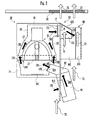
- Fig. 1 is a perspective view showing the schematic construction of the interior of a projector.
- This projector 1 comprises a lamp unit 10, a picture projection unit 30, power su pply circuit boards 40 and 41, a control circuit board 50, and main fans 60 and 70. All of these are mounted upon a chassis 80.
- the lamp unit 10 emits light for picture projection.
- the picture projection unit 30 comprises a picture display device such as a DMD or the like and a color wheel (not shown in the drawings). Using light from the lamp unit 10, this picture projection unit 30 projects a picture which is formed by the picture display device from a projection lens 31.
- the power supply circuit boards 40, 41 supply power to the lamp unit 10 and so on.
- the control circuit board 50 controls the operation of the color wheel and the picture display device and the like, not shown in the figures, which are provided to the picture projection unit 30.
- the main fans 60, 70 are propeller fans, and are fitted to intake apertures 81, 82 which are formed in one side of the chassis 80. These main fans 60, 70 take in external air from the intake apertures 81, 82 and exhaust it from exhaust apertures 83, 84 which hare formed in the opposite side of the chassis 80. Due to this, the interior of the main body of the projector 1 is air cooled. It should be understood that, in Fig. 1, the direction of the flow of air due to the main fans 60, 70 is shown by the white arrows 61, 71. Furthermore, this projector 1 comprises an intake fan 91 for air cooling the.lamp unit 10.
- This intake fan 91 cools a lamp which is provided within the lamp unit 10 by sucking in air which is being blown through the interior of the main body by the main fans 60, 70.
- the air which is discharged from the lamp unit 10 is discharged to the exterior of the main body by the main fans 60, 70.
- Fig. 2 is a cutaway plan view showing the schematic structure of the lamp unit 10, while Fig. 3 is a perspective view showing the structure of the lamp unit 10 and its surroundings.
- the lamp unit 10 comprises a lamp 11 which comprises a lamp bulb 12 and a reflector 13, a front cover 14, a rear cover 15, and a cable (not shown in the figures) which supplies electrical power to the lamp bulb 12 and the like and is housed in a case 16.
- the front cover 14 comprises a projection aperture 141 through which light from the light bulb 12 is projected, and an intake aperture 142 for air cooling the lamp 11.
- the front cover 14 is fitted to the front side of the lamp 11.
- the rear cover 15 is provided with an exhaust aperture 151 for discharging the air which has cooled the lamp bulb 12. Moreover, the exhaust aperture 151 is communicated with an exhaust aperture 18 which is formed in the wall 17 of the case 16. This rear cover 15 is fitted to the rear side of the lamp 11.
- the intake fan 91 is a sirocco type (multi-bladed) fan, and is connected to the duct 92.
- the exhaust aperture 921 of the duct 92 is joined to the intake aperture 142 of the front cover 14 of the lamp unit 10.
- the direction control plate 93 comprises an upper plate 931, a side plate 932, and a lower plate 933.
- This direction control plate 93 is fitted around three sides of the periphery of the exhaust aperture 151 (18), in other words, so as to surround the upper and lower sides of the exhaust aperture 151 (18) and the downstream side of the exhaust 73 of the main fan 70 around three sides thereof in the shape of a letter "U". Furthermore, the side plate 932 is inclined at an angle of ⁇ in the central direction of the main body of the projector 1 with respect to the wall 17 of the case 16, so as to block up the exhaust aperture 18 to a certain extent.
- This direction control plate 93 is provided so as to control the direction of the exhaust from the lamp unit 10, and so as, if the lamp 11 should fail, to prevent broken pieces from flying off.
- the partition plate 94 comprises a side plate 941 and a lower plate 942. This partition plate 94 is fitted at a fixed distance from the direction control plate 93, so as to surround the front side and the bottom side of the exhaust aperture 151 (18) and the direction control plate 93 in the shape of a letter "L".
- the partition plate 94 is provided in order, if the lamp 11 should fail, to prevent broken pieces from flying off.
- the intake fan 91 sucks in, from the intake aperture 911, air which has been brought into the interior of the main body by the main fan 70, and blows it via the duct 92 into the front cover 14. This air which has been blown into the front cover 14 passes around the periphery of the reflector 13 of the lamp 11, and is discharged from the exhaust aperture 151 of the rear cover 15.
- the discharge direction of the air which is thus discharged from the exhaust aperture 151 is controlled by the direction control plate 93, and it is discharged towards the center side of the device main body. And this air which is discharged from the exhaust aperture 151 strikes the partition plate 94, and is then discharged to the exterior of the device main body, along with the air blown by the main fan 70.
- the partition plate 94 Since, in this manner, the partition plate 94 is installed so as to be a fixed distance away from the direction control plate 93, accordingly the air flow due to the main fan 70 passes between the direction control plate 93 and the partition plate 94.
- the air flow 74 which passes the direction control plate 93 collides with the side plate 932, and flows in the direction of the air flow 109 which is discharged from the exhaust aperture 151. And these collide with the side plate 941 of the partition plate 94, and flow in the direction of the air flow 75. Accordingly, if for any reason the lamp 11 breaks, and some broken shards of the lamp 11 are included in the exhaust from the exhaust aperture 151 (18), then some of these broken pieces will collide with the side plate 932 of the direction control plate 93 and will fall down.
- the side plate 932 of the direction control plate 93 is inclined at the angle ⁇ with respect to the wall 17 of the case 16. Due to this, the side plate 932 controls the direction of the air flow so that, if broken pieces of a lamp 11 are included in the exhaust from the lamp unit 10, these broken pieces are scattered in the direction of the center of the main body of the projector 1. Due to this, it is possible to prevent the broken pieces from being scattered to the outside of the lower plate 942 of the partition plate 94.
- Fig. 4 is a perspective view showing an alternative structure for the lamp unit and its surrounding elements, different from that shown in Fig. 3.
- the partition plate 94 is not limited to being formed in the shape of a letter "L"; it would also be acceptable for it to be of some other shape.
- the lower plate 943 may be formed in the shape of a box without a lid. Since, with this structure, the partition plate 94 assumes a shape like a pocket, accordingly the broken pieces do not fall from the lower plate 943 of the partition plate 94 to the outside thereof, but rather, such broken pieces can be accumulated upon the lower plate 943 of the partition plate 94.
- the partition plate 94 it would also be possible for the partition plate 94 to be made in a mesh form, for example using a wire net or the like. At this time, it is preferable to adjust the size of this mesh so that the broken pieces of the lamp 11 which pass the partition plate in the form of a mesh are not scattered towards the power supply circuit boards 40, 41 or the control circuit board 50 or the like.
Landscapes
- Engineering & Computer Science (AREA)
- Multimedia (AREA)
- Signal Processing (AREA)
- Physics & Mathematics (AREA)
- General Physics & Mathematics (AREA)
- Projection Apparatus (AREA)
- Arrangement Of Elements, Cooling, Sealing, Or The Like Of Lighting Devices (AREA)
- Non-Portable Lighting Devices Or Systems Thereof (AREA)
Abstract
Description
- The present invention relates to a structure which, upon failure of the lamp of a projector, prevents scattering of broken pieces of the lamp to the exterior of the projector main body.
- Recently, a type of projector has become widespread which irradiates light from a lamp upon a picture display device such as a digital micromirror device (DMD) or a liquid crystal display device or the like, and projects a picture which is displayed upon this picture display device upon a screen.
- With this type of projector, sometimes for one reason or another the lamp which is used as a light source fails, and may break. Due to this, in order for the user not to be injured by the broken pieces of the lamp, inventions have been disclosed related to a projector or to a projection type display device which is built so that, upon failure of the lamp, the broken pieces do not scatter directly to the exterior.
- With the liquid crystal projector described in
Japanese Laid-Open Patent Publication 2001-216536 - Furthermore, with the projection type display device described in
Japanese Laid-Open Patent Publication 2003-344949 - The object of the present invention is to provide a projector with which dust does not collect in an intake aperture or an exhaust aperture for cooling the lamp unit, and moreover with which, upon damage to the lamp, broken pieces of a size greater than that determined by the safety standard are not scattered to the exterior.
- The projector according to the present invention includes a lamp unit, in the external wall of which an intake aperture and an exhaust aperture are formed, and in the interior of which a lamp is installed. Moreover it includes an intake fan which sucks in air from said intake aperture and cools said lamp therewith, and a partition plate which is installed so as to face forward of said exhaust aperture of said lamp unit.
- Since, even if broken pieces of the lamp are scattered from the exhaust aperture of the lamp unit, they collide with the partition plate and fall down, accordingly it is possible to prevent these broken pieces of the lamp from being scattered to the exterior of the projector. Furthermore, since it is possible to prevent such broken pieces of the lamp from being scattered even though no nets are fitted to the exhaust apertures, accordingly it is possible to prevent the venting characteristics from becoming bad due to dust accumulating in the exhaust apertures.
-
- Fig. 1 is a perspective view showing the schematic internal construction of a projector;
- Fig. 2 is a cutaway plan view showing the schematic structure of a lamp unit;
- Fig. 3 is a perspective view showing the structure of the lamp unit and its surroundings; and
- Fig. 4 is a perspective view showing a structure for the lamp unit and its surroundings, different from that shown in Fig. 3.
- Fig. 1 is a perspective view showing the schematic construction of the interior of a projector. This projector 1 comprises a
lamp unit 10, apicture projection unit 30, power supply circuit boards 40 and 41, a control circuit board 50, andmain fans 60 and 70. All of these are mounted upon achassis 80. Thelamp unit 10 emits light for picture projection. Thepicture projection unit 30 comprises a picture display device such as a DMD or the like and a color wheel (not shown in the drawings). Using light from thelamp unit 10, thispicture projection unit 30 projects a picture which is formed by the picture display device from a projection lens 31. The powersupply circuit boards 40, 41 supply power to thelamp unit 10 and so on. The control circuit board 50 controls the operation of the color wheel and the picture display device and the like, not shown in the figures, which are provided to thepicture projection unit 30. - The
main fans 60, 70 are propeller fans, and are fitted to intakeapertures chassis 80. Thesemain fans 60, 70 take in external air from theintake apertures exhaust apertures chassis 80. Due to this, the interior of the main body of the projector 1 is air cooled. It should be understood that, in Fig. 1, the direction of the flow of air due to themain fans 60, 70 is shown by thewhite arrows 61, 71. Furthermore, this projector 1 comprises anintake fan 91 for air cooling the.lamp unit 10. Thisintake fan 91 cools a lamp which is provided within thelamp unit 10 by sucking in air which is being blown through the interior of the main body by themain fans 60, 70. The air which is discharged from thelamp unit 10 is discharged to the exterior of the main body by themain fans 60, 70. - Fig. 2 is a cutaway plan view showing the schematic structure of the
lamp unit 10, while Fig. 3 is a perspective view showing the structure of thelamp unit 10 and its surroundings. As shown in Fig. 2, thelamp unit 10 comprises a lamp 11 which comprises alamp bulb 12 and areflector 13, afront cover 14, arear cover 15, and a cable (not shown in the figures) which supplies electrical power to thelamp bulb 12 and the like and is housed in acase 16. Thefront cover 14 comprises aprojection aperture 141 through which light from thelight bulb 12 is projected, and anintake aperture 142 for air cooling the lamp 11. Thefront cover 14 is fitted to the front side of the lamp 11. - The
rear cover 15 is provided with anexhaust aperture 151 for discharging the air which has cooled thelamp bulb 12. Moreover, theexhaust aperture 151 is communicated with an exhaust aperture 18 which is formed in thewall 17 of thecase 16. Thisrear cover 15 is fitted to the rear side of the lamp 11. - Furthermore, as shown in Figs. 2 and 3, to the
lamp unit 10, there are fitted theintake fan 91, aduct 92, adirection control plate 93, and apartition plate 94. Theintake fan 91 is a sirocco type (multi-bladed) fan, and is connected to theduct 92. Theexhaust aperture 921 of theduct 92 is joined to theintake aperture 142 of thefront cover 14 of thelamp unit 10. Thedirection control plate 93 comprises anupper plate 931, aside plate 932, and alower plate 933. Thisdirection control plate 93 is fitted around three sides of the periphery of the exhaust aperture 151 (18), in other words, so as to surround the upper and lower sides of the exhaust aperture 151 (18) and the downstream side of theexhaust 73 of the main fan 70 around three sides thereof in the shape of a letter "U". Furthermore, theside plate 932 is inclined at an angle of θ in the central direction of the main body of the projector 1 with respect to thewall 17 of thecase 16, so as to block up the exhaust aperture 18 to a certain extent. Thisdirection control plate 93 is provided so as to control the direction of the exhaust from
thelamp unit 10, and so as, if the lamp 11 should fail, to prevent broken pieces from flying off. - The
partition plate 94 comprises aside plate 941 and alower plate 942. Thispartition plate 94 is fitted at a fixed distance from thedirection control plate 93, so as to surround the front side and the bottom side of the exhaust aperture 151 (18) and thedirection control plate 93 in the shape of a letter "L". Thepartition plate 94 is provided in order, if the lamp 11 should fail, to prevent broken pieces from flying off. - Next, the interior of the main body of the projector 1 and the
lamp unit 10 are cooled by the flow of air, as shown by thewhite arrows 72 ~ 76 and theblack arrows 101 ~ 109 in Fig. 2. First, theintake fan 91 sucks in, from theintake aperture 911, air which has been brought into the interior of the main body by the main fan 70, and blows it via theduct 92 into thefront cover 14. This air which has been blown into thefront cover 14 passes around the periphery of thereflector 13 of the lamp 11, and is discharged from theexhaust aperture 151 of therear cover 15. At this time, the discharge direction of the air which is thus discharged from theexhaust aperture 151 is controlled by thedirection control plate 93, and it is discharged towards the center side of the device main body. And this air which is discharged from theexhaust aperture 151 strikes thepartition plate 94, and is then discharged to the exterior of the device main body, along with the air blown by the main fan 70. - Furthermore, with this projector 1, if for any reason the lamp 11 should be broken, then, as explained below, the broken fragments of the lamp 11 are discharged from the
exhaust aperture 151 along with the air that has cooled thelamp unit 10, and, due to thedirection control plate 93 and thepartition plate 94, are prevented from being discharged to the exterior of the main body of the projector 1. - Since, in this manner, the
partition plate 94 is installed so as to be a fixed distance away from thedirection control plate 93, accordingly the air flow due to the main fan 70 passes between thedirection control plate 93 and thepartition plate 94. The air flow 74 which passes thedirection control plate 93 collides with theside plate 932, and flows in the direction of theair flow 109 which is discharged from theexhaust aperture 151. And these collide with theside plate 941 of thepartition plate 94, and flow in the direction of theair flow 75. Accordingly, if for any reason the lamp 11 breaks, and some broken shards of the lamp 11 are included in the exhaust from the exhaust aperture 151 (18), then some of these broken pieces will collide with theside plate 932 of thedirection control plate 93 and will fall down. Furthermore, the majority of these broken pieces will collide with theside plate 941 of thepartition plate 94 and will also fall down. Thus, even if some broken pieces of the lamp 11 are included in the exhaust from thelamp unit 10, since these broken pieces are eliminated due to thedirection control plate 93 and thepartition plate 94, accordingly they are not discharged to the exterior of the device main body along with the flow of air from the main fan 70. - Furthermore, as described above, the
side plate 932 of thedirection control plate 93 is inclined at the angle θ with respect to thewall 17 of thecase 16. Due to this, theside plate 932 controls the direction of the air flow so that, if broken pieces of a lamp 11 are included in the exhaust from thelamp unit 10, these broken pieces are scattered in the direction of the center of the main body of the projector 1. Due to this, it is possible to prevent the broken pieces from being scattered to the outside of thelower plate 942 of thepartition plate 94. - Fig. 4 is a perspective view showing an alternative structure for the lamp unit and its surrounding elements, different from that shown in Fig. 3. The
partition plate 94 is not limited to being formed in the shape of a letter "L"; it would also be acceptable for it to be of some other shape. For example, with thispartition plate 94, thelower plate 943 may be formed in the shape of a box without a lid. Since, with this structure, thepartition plate 94 assumes a shape like a pocket, accordingly the broken pieces do not fall from thelower plate 943 of thepartition plate 94 to the outside thereof, but rather, such broken pieces can be accumulated upon thelower plate 943 of thepartition plate 94. - Moreover, it would also be acceptable to arrange to stick some shock absorption material such as sponge or the like to the
partition plate 94. By doing this, when the broken pieces of the lamp 11 collide with thepartition plate 94, it is possible to reduce the speed of these broken pieces. Accordingly, along with the broken pieces being thrown back after collision with thepartition plate 94 and then being exhausted for a second time, it is possible to prevent them from being discharged to the exterior of the main body of the projector 1. - Furthermore, it would also be possible for the
partition plate 94 to be made in a mesh form, for example using a wire net or the like. At this time, it is preferable to adjust the size of this mesh so that the broken pieces of the lamp 11 which pass the partition plate in the form of a mesh are not scattered towards the powersupply circuit boards 40, 41 or the control circuit board 50 or the like. - Yet further, it would also be possible to fix exchangeable nets to the
exhaust apertures chassis 80. At this time, with regard to the size of the holes in these nets, it is desirable to employ a size such that broken pieces of the lamp 11 of a size greater than that prescribed by the safety standard are not scattered to the exterior of the main body of the projector 1. By doing this, even if it has not been possible to cause all of the broken pieces to fall down due to the action of thedirection control plate 93 and thepartition plate 94, it may still be ensured than only broken pieces of size less than 0.8 mm2 are discharged to the exterior of the main body of the projector 1, as prescribed by the safety standard. - As described above, even if for some reason the lamp of the
lamp unit 10 should be broken, and broken pieces thereof should be discharged along with the exhaust, it is possible to ensure that these broken pieces should collide with thedirection control plate 93 and thepartition plate 94. Due to this, the broken pieces of the lamp 11 are not discharged to the exterior of the main body of the projector 1. - Finally, in the above described explanation of an embodiment of the present invention, all of the features are shown by way of example, and should not be considered as being limitative of the present invention. The scope of the present invention is not to be defined by any of the features of the embodiment described above, but only by the scope of the appended Claims. Moreover, equivalents to elements in the Claims, and variations within their legitimate and proper scope, are also to be considered as being included within the range of the present invention.
Claims (4)
- A projector (1), comprising:a lamp unit (10), in an external wall (14, 15) of which an intake aperture (142) and an exhaust aperture (151, 18) are formed, and in the interior of which a lamp (11) is installed,characterized by:an intake fan (91) which sucks in air from said intake aperture (142) and cools said lamp (11) therewith; anda partition plate (94) which is installed so as to face forward of said exhaust aperture (151, 18) of said lamp unit (10).
- A projector (1) as described in Claim 1, further comprising:a main fan (60, 70) which discharges exhaust from said lamp unit (10) to the exterior of the device main body; anda direction control plate (93) which is erected near said exhaust aperture (18), and at the downstream side of the exhaust of said main fan (60, 70).
- A projector (1) as described in Claim 2, wherein said direction control plate (93) is inclined in a direction to close said exhaust aperture (18).
- A projector (1) as described in Claim 1 or 3, wherein said partition plate (94) comprises a bottom portion (943) of a box shape, below said exhaust aperture (18).
Applications Claiming Priority (1)
| Application Number | Priority Date | Filing Date | Title |
|---|---|---|---|
| JP2006071257A JP2007248760A (en) | 2006-03-15 | 2006-03-15 | projector |
Publications (2)
| Publication Number | Publication Date |
|---|---|
| EP1835736A1 true EP1835736A1 (en) | 2007-09-19 |
| EP1835736B1 EP1835736B1 (en) | 2011-05-11 |
Family
ID=38055179
Family Applications (1)
| Application Number | Title | Priority Date | Filing Date |
|---|---|---|---|
| EP07005199A Not-in-force EP1835736B1 (en) | 2006-03-15 | 2007-03-13 | Projector |
Country Status (4)
| Country | Link |
|---|---|
| US (1) | US7963659B2 (en) |
| EP (1) | EP1835736B1 (en) |
| JP (1) | JP2007248760A (en) |
| CN (1) | CN100552535C (en) |
Families Citing this family (12)
| Publication number | Priority date | Publication date | Assignee | Title |
|---|---|---|---|---|
| US9140968B2 (en) * | 2007-06-29 | 2015-09-22 | Seiko Epson Corporation | Projection device particle-containment shield |
| CN101988660B (en) * | 2009-08-07 | 2014-03-26 | 扬光绿能股份有限公司 | Light source module and projection system |
| TWI417634B (en) * | 2009-08-18 | 2013-12-01 | Qisda Corp | Projector |
| CN101644878B (en) * | 2009-09-03 | 2012-01-04 | 苏州佳世达光电有限公司 | Projecting device |
| JP5648294B2 (en) * | 2010-02-18 | 2015-01-07 | ソニー株式会社 | Projector device |
| TWI459123B (en) * | 2013-01-17 | 2014-11-01 | Hon Hai Prec Ind Co Ltd | Cooling apparatus of porjector |
| JP6435677B2 (en) * | 2014-07-15 | 2018-12-12 | セイコーエプソン株式会社 | projector |
| JP6439462B2 (en) * | 2015-01-28 | 2018-12-19 | セイコーエプソン株式会社 | Light source device and projector |
| JP6443083B2 (en) * | 2015-01-28 | 2018-12-26 | セイコーエプソン株式会社 | Dust collector and projector |
| CN105333408B (en) * | 2015-12-03 | 2019-02-19 | 广州市浩洋电子股份有限公司 | A stage light source module thermal system |
| KR101882449B1 (en) * | 2018-01-19 | 2018-07-27 | 더좋은생활 주식회사 | Modular LED lighting including an air guide to create an air stream |
| CN111610685B (en) | 2019-02-26 | 2022-05-10 | 中强光电股份有限公司 | Light source heat dissipation device and projector |
Citations (3)
| Publication number | Priority date | Publication date | Assignee | Title |
|---|---|---|---|---|
| US20010021006A1 (en) * | 2000-03-10 | 2001-09-13 | Nec Corporation | Lamp House and projector device thereof |
| JP2002352604A (en) * | 2001-05-30 | 2002-12-06 | Seiko Epson Corp | Light source device, lamp unit and projector |
| US20040263799A1 (en) * | 2003-06-24 | 2004-12-30 | Seon-Woo Lim | Image projection apparatus |
Family Cites Families (9)
| Publication number | Priority date | Publication date | Assignee | Title |
|---|---|---|---|---|
| JP2001216536A (en) | 2000-01-31 | 2001-08-10 | Tamura Electric Works Ltd | Card issuing machine |
| TW524319U (en) * | 2002-03-22 | 2003-03-11 | Coretronic Corp | Heat dissipating structure of projector |
| JP2003344949A (en) | 2002-05-23 | 2003-12-03 | Mitsubishi Electric Corp | Exhaust duct for projection display device and projection display device |
| US7052147B2 (en) * | 2003-02-20 | 2006-05-30 | Seiko Epson Corporation | Light source, and projector provided with the light source |
| JP4196913B2 (en) * | 2004-09-14 | 2008-12-17 | ソニー株式会社 | Projector device |
| JP4221353B2 (en) * | 2004-11-19 | 2009-02-12 | Necディスプレイソリューションズ株式会社 | Light source device and projection display device |
| JP2006189650A (en) * | 2005-01-06 | 2006-07-20 | Toshiba Corp | Projection display device and cooling structure |
| JP2006260865A (en) * | 2005-03-16 | 2006-09-28 | Mitsubishi Electric Corp | Light source device and projection-type image display device |
| JP2007279331A (en) * | 2006-04-06 | 2007-10-25 | Funai Electric Co Ltd | Projector |
-
2006
- 2006-03-15 JP JP2006071257A patent/JP2007248760A/en active Pending
-
2007
- 2007-03-13 EP EP07005199A patent/EP1835736B1/en not_active Not-in-force
- 2007-03-14 US US11/717,649 patent/US7963659B2/en not_active Expired - Fee Related
- 2007-03-15 CN CNB2007100863538A patent/CN100552535C/en not_active Expired - Fee Related
Patent Citations (3)
| Publication number | Priority date | Publication date | Assignee | Title |
|---|---|---|---|---|
| US20010021006A1 (en) * | 2000-03-10 | 2001-09-13 | Nec Corporation | Lamp House and projector device thereof |
| JP2002352604A (en) * | 2001-05-30 | 2002-12-06 | Seiko Epson Corp | Light source device, lamp unit and projector |
| US20040263799A1 (en) * | 2003-06-24 | 2004-12-30 | Seon-Woo Lim | Image projection apparatus |
Also Published As
| Publication number | Publication date |
|---|---|
| CN100552535C (en) | 2009-10-21 |
| JP2007248760A (en) | 2007-09-27 |
| CN101038430A (en) | 2007-09-19 |
| US20070216874A1 (en) | 2007-09-20 |
| US7963659B2 (en) | 2011-06-21 |
| EP1835736B1 (en) | 2011-05-11 |
Similar Documents
| Publication | Publication Date | Title |
|---|---|---|
| EP1835736B1 (en) | Projector | |
| EP1843190A2 (en) | Projector | |
| CN101498887B (en) | Digital Light Processing Projection Device | |
| JP2021033037A (en) | Picture display device | |
| JP2006267622A (en) | Lamp cooling device and projection display device | |
| JP2006084589A (en) | Projector device | |
| US7040763B2 (en) | Image display device | |
| CN106873288A (en) | Image projecting equipment | |
| JPH09185124A (en) | Lamp device for liquid crystal projection device | |
| JP2008129365A (en) | Projector | |
| US20110279790A1 (en) | Projection display device | |
| JP2011242491A (en) | Projection type display device | |
| US9022574B2 (en) | Display device | |
| JP2004294749A (en) | Light source device | |
| JP2002365728A5 (en) | ||
| EP0071158A1 (en) | Display device | |
| JP2001125195A (en) | Light source device and display device using the same | |
| JP2005316177A (en) | Lamp unit and projection type display device | |
| US7726817B2 (en) | Projector with lamp unit having a U-shaped insertion frame | |
| JPWO2018138805A1 (en) | Switch gear | |
| JP2004219752A (en) | Video projection device and cooling method for video projection device | |
| US20070242232A1 (en) | Electronic device and guiding device | |
| JP3788617B2 (en) | Image display projector | |
| JP2000252675A (en) | Electronic equipment cooling device | |
| CN223850450U (en) | A ventilation and dustproof device for a charging pile and a dustproof car charging pile |
Legal Events
| Date | Code | Title | Description |
|---|---|---|---|
| PUAI | Public reference made under article 153(3) epc to a published international application that has entered the european phase |
Free format text: ORIGINAL CODE: 0009012 |
|
| AK | Designated contracting states |
Kind code of ref document: A1 Designated state(s): AT BE BG CH CY CZ DE DK EE ES FI FR GB GR HU IE IS IT LI LT LU LV MC MT NL PL PT RO SE SI SK TR |
|
| AX | Request for extension of the european patent |
Extension state: AL BA HR MK YU |
|
| 17P | Request for examination filed |
Effective date: 20071213 |
|
| 17Q | First examination report despatched |
Effective date: 20080117 |
|
| AKX | Designation fees paid |
Designated state(s): DE FR GB |
|
| GRAP | Despatch of communication of intention to grant a patent |
Free format text: ORIGINAL CODE: EPIDOSNIGR1 |
|
| GRAS | Grant fee paid |
Free format text: ORIGINAL CODE: EPIDOSNIGR3 |
|
| GRAA | (expected) grant |
Free format text: ORIGINAL CODE: 0009210 |
|
| AK | Designated contracting states |
Kind code of ref document: B1 Designated state(s): DE FR GB |
|
| REG | Reference to a national code |
Ref country code: GB Ref legal event code: FG4D |
|
| REG | Reference to a national code |
Ref country code: DE Ref legal event code: R096 Ref document number: 602007014433 Country of ref document: DE Effective date: 20110622 |
|
| PLBE | No opposition filed within time limit |
Free format text: ORIGINAL CODE: 0009261 |
|
| STAA | Information on the status of an ep patent application or granted ep patent |
Free format text: STATUS: NO OPPOSITION FILED WITHIN TIME LIMIT |
|
| 26N | No opposition filed |
Effective date: 20120214 |
|
| REG | Reference to a national code |
Ref country code: DE Ref legal event code: R097 Ref document number: 602007014433 Country of ref document: DE Effective date: 20120214 |
|
| PGFP | Annual fee paid to national office [announced via postgrant information from national office to epo] |
Ref country code: FR Payment date: 20140311 Year of fee payment: 8 |
|
| PGFP | Annual fee paid to national office [announced via postgrant information from national office to epo] |
Ref country code: GB Payment date: 20140312 Year of fee payment: 8 |
|
| PGFP | Annual fee paid to national office [announced via postgrant information from national office to epo] |
Ref country code: DE Payment date: 20140417 Year of fee payment: 8 |
|
| REG | Reference to a national code |
Ref country code: DE Ref legal event code: R119 Ref document number: 602007014433 Country of ref document: DE |
|
| GBPC | Gb: european patent ceased through non-payment of renewal fee |
Effective date: 20150313 |
|
| REG | Reference to a national code |
Ref country code: FR Ref legal event code: ST Effective date: 20151130 |
|
| PG25 | Lapsed in a contracting state [announced via postgrant information from national office to epo] |
Ref country code: GB Free format text: LAPSE BECAUSE OF NON-PAYMENT OF DUE FEES Effective date: 20150313 Ref country code: DE Free format text: LAPSE BECAUSE OF NON-PAYMENT OF DUE FEES Effective date: 20151001 |
|
| PG25 | Lapsed in a contracting state [announced via postgrant information from national office to epo] |
Ref country code: FR Free format text: LAPSE BECAUSE OF NON-PAYMENT OF DUE FEES Effective date: 20150331 |