EP1835715A2 - Image processing apparatus and method with preview display of images subjected to selected processing options - Google Patents
Image processing apparatus and method with preview display of images subjected to selected processing options Download PDFInfo
- Publication number
- EP1835715A2 EP1835715A2 EP07251076A EP07251076A EP1835715A2 EP 1835715 A2 EP1835715 A2 EP 1835715A2 EP 07251076 A EP07251076 A EP 07251076A EP 07251076 A EP07251076 A EP 07251076A EP 1835715 A2 EP1835715 A2 EP 1835715A2
- Authority
- EP
- European Patent Office
- Prior art keywords
- image
- read
- preview image
- document
- user
- Prior art date
- Legal status (The legal status is an assumption and is not a legal conclusion. Google has not performed a legal analysis and makes no representation as to the accuracy of the status listed.)
- Granted
Links
- 238000012545 processing Methods 0.000 title claims abstract description 218
- 238000000034 method Methods 0.000 title claims description 98
- 230000008569 process Effects 0.000 claims description 60
- 230000002194 synthesizing effect Effects 0.000 claims description 12
- 238000007730 finishing process Methods 0.000 claims description 4
- 238000004590 computer program Methods 0.000 claims 1
- 230000000694 effects Effects 0.000 claims 1
- 238000010586 diagram Methods 0.000 description 100
- 101150013335 img1 gene Proteins 0.000 description 69
- 230000015572 biosynthetic process Effects 0.000 description 37
- 238000003786 synthesis reaction Methods 0.000 description 37
- 230000002776 aggregation Effects 0.000 description 18
- 238000004220 aggregation Methods 0.000 description 18
- 230000006870 function Effects 0.000 description 11
- 230000006835 compression Effects 0.000 description 9
- 238000007906 compression Methods 0.000 description 9
- 238000012546 transfer Methods 0.000 description 9
- 230000004931 aggregating effect Effects 0.000 description 7
- 238000011161 development Methods 0.000 description 7
- 230000009467 reduction Effects 0.000 description 6
- 230000008859 change Effects 0.000 description 4
- 239000004973 liquid crystal related substance Substances 0.000 description 3
- 238000004364 calculation method Methods 0.000 description 2
- 238000012015 optical character recognition Methods 0.000 description 2
- 238000004080 punching Methods 0.000 description 2
- 101100438124 Arabidopsis thaliana CYP81F2 gene Proteins 0.000 description 1
- 238000007796 conventional method Methods 0.000 description 1
- 238000012986 modification Methods 0.000 description 1
- 230000004048 modification Effects 0.000 description 1
- 230000002093 peripheral effect Effects 0.000 description 1
- 101150096886 sft-1 gene Proteins 0.000 description 1
Images























Classifications
-
- G—PHYSICS
- G03—PHOTOGRAPHY; CINEMATOGRAPHY; ANALOGOUS TECHNIQUES USING WAVES OTHER THAN OPTICAL WAVES; ELECTROGRAPHY; HOLOGRAPHY
- G03G—ELECTROGRAPHY; ELECTROPHOTOGRAPHY; MAGNETOGRAPHY
- G03G15/00—Apparatus for electrographic processes using a charge pattern
- G03G15/65—Apparatus which relate to the handling of copy material
- G03G15/6538—Devices for collating sheet copy material, e.g. sorters, control, copies in staples form
- G03G15/6541—Binding sets of sheets, e.g. by stapling, glueing
-
- G—PHYSICS
- G03—PHOTOGRAPHY; CINEMATOGRAPHY; ANALOGOUS TECHNIQUES USING WAVES OTHER THAN OPTICAL WAVES; ELECTROGRAPHY; HOLOGRAPHY
- G03G—ELECTROGRAPHY; ELECTROPHOTOGRAPHY; MAGNETOGRAPHY
- G03G15/00—Apparatus for electrographic processes using a charge pattern
- G03G15/50—Machine control of apparatus for electrographic processes using a charge pattern, e.g. regulating differents parts of the machine, multimode copiers, microprocessor control
- G03G15/5016—User-machine interface; Display panels; Control console
- G03G15/502—User-machine interface; Display panels; Control console relating to the structure of the control menu, e.g. pop-up menus, help screens
-
- G—PHYSICS
- G03—PHOTOGRAPHY; CINEMATOGRAPHY; ANALOGOUS TECHNIQUES USING WAVES OTHER THAN OPTICAL WAVES; ELECTROGRAPHY; HOLOGRAPHY
- G03G—ELECTROGRAPHY; ELECTROPHOTOGRAPHY; MAGNETOGRAPHY
- G03G15/00—Apparatus for electrographic processes using a charge pattern
- G03G15/65—Apparatus which relate to the handling of copy material
- G03G15/6582—Special processing for irreversibly adding or changing the sheet copy material characteristics or its appearance, e.g. stamping, annotation printing, punching
-
- H—ELECTRICITY
- H04—ELECTRIC COMMUNICATION TECHNIQUE
- H04N—PICTORIAL COMMUNICATION, e.g. TELEVISION
- H04N1/00—Scanning, transmission or reproduction of documents or the like, e.g. facsimile transmission; Details thereof
- H04N1/0035—User-machine interface; Control console
- H04N1/00405—Output means
- H04N1/00408—Display of information to the user, e.g. menus
- H04N1/00411—Display of information to the user, e.g. menus the display also being used for user input, e.g. touch screen
-
- H—ELECTRICITY
- H04—ELECTRIC COMMUNICATION TECHNIQUE
- H04N—PICTORIAL COMMUNICATION, e.g. TELEVISION
- H04N1/00—Scanning, transmission or reproduction of documents or the like, e.g. facsimile transmission; Details thereof
- H04N1/0035—User-machine interface; Control console
- H04N1/00405—Output means
- H04N1/00408—Display of information to the user, e.g. menus
- H04N1/00413—Display of information to the user, e.g. menus using menus, i.e. presenting the user with a plurality of selectable options
-
- H—ELECTRICITY
- H04—ELECTRIC COMMUNICATION TECHNIQUE
- H04N—PICTORIAL COMMUNICATION, e.g. TELEVISION
- H04N1/00—Scanning, transmission or reproduction of documents or the like, e.g. facsimile transmission; Details thereof
- H04N1/0035—User-machine interface; Control console
- H04N1/00405—Output means
- H04N1/00408—Display of information to the user, e.g. menus
- H04N1/00413—Display of information to the user, e.g. menus using menus, i.e. presenting the user with a plurality of selectable options
- H04N1/00416—Multi-level menus
- H04N1/00419—Arrangements for navigating between pages or parts of the menu
- H04N1/00432—Arrangements for navigating between pages or parts of the menu using tabs
-
- H—ELECTRICITY
- H04—ELECTRIC COMMUNICATION TECHNIQUE
- H04N—PICTORIAL COMMUNICATION, e.g. TELEVISION
- H04N1/00—Scanning, transmission or reproduction of documents or the like, e.g. facsimile transmission; Details thereof
- H04N1/0035—User-machine interface; Control console
- H04N1/00405—Output means
- H04N1/00408—Display of information to the user, e.g. menus
- H04N1/0044—Display of information to the user, e.g. menus for image preview or review, e.g. to help the user position a sheet
- H04N1/00442—Simultaneous viewing of a plurality of images, e.g. using a mosaic display arrangement of thumbnails
-
- H—ELECTRICITY
- H04—ELECTRIC COMMUNICATION TECHNIQUE
- H04N—PICTORIAL COMMUNICATION, e.g. TELEVISION
- H04N1/00—Scanning, transmission or reproduction of documents or the like, e.g. facsimile transmission; Details thereof
- H04N1/0035—User-machine interface; Control console
- H04N1/00405—Output means
- H04N1/00408—Display of information to the user, e.g. menus
- H04N1/0044—Display of information to the user, e.g. menus for image preview or review, e.g. to help the user position a sheet
- H04N1/00442—Simultaneous viewing of a plurality of images, e.g. using a mosaic display arrangement of thumbnails
- H04N1/00445—Simultaneous viewing of a plurality of images, e.g. using a mosaic display arrangement of thumbnails arranged in a one dimensional array
- H04N1/00448—Simultaneous viewing of a plurality of images, e.g. using a mosaic display arrangement of thumbnails arranged in a one dimensional array horizontally
-
- H—ELECTRICITY
- H04—ELECTRIC COMMUNICATION TECHNIQUE
- H04N—PICTORIAL COMMUNICATION, e.g. TELEVISION
- H04N1/00—Scanning, transmission or reproduction of documents or the like, e.g. facsimile transmission; Details thereof
- H04N1/0035—User-machine interface; Control console
- H04N1/00405—Output means
- H04N1/00408—Display of information to the user, e.g. menus
- H04N1/0044—Display of information to the user, e.g. menus for image preview or review, e.g. to help the user position a sheet
- H04N1/00442—Simultaneous viewing of a plurality of images, e.g. using a mosaic display arrangement of thumbnails
- H04N1/00445—Simultaneous viewing of a plurality of images, e.g. using a mosaic display arrangement of thumbnails arranged in a one dimensional array
- H04N1/0045—Simultaneous viewing of a plurality of images, e.g. using a mosaic display arrangement of thumbnails arranged in a one dimensional array vertically
-
- H—ELECTRICITY
- H04—ELECTRIC COMMUNICATION TECHNIQUE
- H04N—PICTORIAL COMMUNICATION, e.g. TELEVISION
- H04N1/00—Scanning, transmission or reproduction of documents or the like, e.g. facsimile transmission; Details thereof
- H04N1/0035—User-machine interface; Control console
- H04N1/00405—Output means
- H04N1/00408—Display of information to the user, e.g. menus
- H04N1/0044—Display of information to the user, e.g. menus for image preview or review, e.g. to help the user position a sheet
- H04N1/00442—Simultaneous viewing of a plurality of images, e.g. using a mosaic display arrangement of thumbnails
- H04N1/00453—Simultaneous viewing of a plurality of images, e.g. using a mosaic display arrangement of thumbnails arranged in a two dimensional array
-
- H—ELECTRICITY
- H04—ELECTRIC COMMUNICATION TECHNIQUE
- H04N—PICTORIAL COMMUNICATION, e.g. TELEVISION
- H04N1/00—Scanning, transmission or reproduction of documents or the like, e.g. facsimile transmission; Details thereof
- H04N1/0035—User-machine interface; Control console
- H04N1/00405—Output means
- H04N1/00408—Display of information to the user, e.g. menus
- H04N1/0044—Display of information to the user, e.g. menus for image preview or review, e.g. to help the user position a sheet
- H04N1/00442—Simultaneous viewing of a plurality of images, e.g. using a mosaic display arrangement of thumbnails
- H04N1/00456—Simultaneous viewing of a plurality of images, e.g. using a mosaic display arrangement of thumbnails for layout preview, e.g. page layout
-
- H—ELECTRICITY
- H04—ELECTRIC COMMUNICATION TECHNIQUE
- H04N—PICTORIAL COMMUNICATION, e.g. TELEVISION
- H04N1/00—Scanning, transmission or reproduction of documents or the like, e.g. facsimile transmission; Details thereof
- H04N1/0035—User-machine interface; Control console
- H04N1/00405—Output means
- H04N1/00408—Display of information to the user, e.g. menus
- H04N1/0044—Display of information to the user, e.g. menus for image preview or review, e.g. to help the user position a sheet
- H04N1/00458—Sequential viewing of a plurality of images, e.g. browsing or scrolling
-
- H—ELECTRICITY
- H04—ELECTRIC COMMUNICATION TECHNIQUE
- H04N—PICTORIAL COMMUNICATION, e.g. TELEVISION
- H04N1/00—Scanning, transmission or reproduction of documents or the like, e.g. facsimile transmission; Details thereof
- H04N1/0035—User-machine interface; Control console
- H04N1/00405—Output means
- H04N1/00408—Display of information to the user, e.g. menus
- H04N1/00466—Display of information to the user, e.g. menus displaying finishing information, e.g. position of punch holes or staple or orientation references
-
- H—ELECTRICITY
- H04—ELECTRIC COMMUNICATION TECHNIQUE
- H04N—PICTORIAL COMMUNICATION, e.g. TELEVISION
- H04N1/00—Scanning, transmission or reproduction of documents or the like, e.g. facsimile transmission; Details thereof
- H04N1/0035—User-machine interface; Control console
- H04N1/00405—Output means
- H04N1/00408—Display of information to the user, e.g. menus
- H04N1/00472—Display of information to the user, e.g. menus using a pop-up window
-
- H—ELECTRICITY
- H04—ELECTRIC COMMUNICATION TECHNIQUE
- H04N—PICTORIAL COMMUNICATION, e.g. TELEVISION
- H04N1/00—Scanning, transmission or reproduction of documents or the like, e.g. facsimile transmission; Details thereof
- H04N1/0035—User-machine interface; Control console
- H04N1/00405—Output means
- H04N1/0048—Indicating an illegal or impossible operation or selection to the user
-
- H—ELECTRICITY
- H04—ELECTRIC COMMUNICATION TECHNIQUE
- H04N—PICTORIAL COMMUNICATION, e.g. TELEVISION
- H04N1/00—Scanning, transmission or reproduction of documents or the like, e.g. facsimile transmission; Details thereof
- H04N1/0035—User-machine interface; Control console
- H04N1/00405—Output means
- H04N1/00482—Output means outputting a plurality of job set-up options, e.g. number of copies, paper size or resolution
-
- H—ELECTRICITY
- H04—ELECTRIC COMMUNICATION TECHNIQUE
- H04N—PICTORIAL COMMUNICATION, e.g. TELEVISION
- H04N1/00—Scanning, transmission or reproduction of documents or the like, e.g. facsimile transmission; Details thereof
- H04N1/00567—Handling of original or reproduction media, e.g. cutting, separating, stacking
-
- H—ELECTRICITY
- H04—ELECTRIC COMMUNICATION TECHNIQUE
- H04N—PICTORIAL COMMUNICATION, e.g. TELEVISION
- H04N1/00—Scanning, transmission or reproduction of documents or the like, e.g. facsimile transmission; Details thereof
- H04N1/00567—Handling of original or reproduction media, e.g. cutting, separating, stacking
- H04N1/00639—Binding, stapling, folding or perforating, e.g. punching
-
- H—ELECTRICITY
- H04—ELECTRIC COMMUNICATION TECHNIQUE
- H04N—PICTORIAL COMMUNICATION, e.g. TELEVISION
- H04N1/00—Scanning, transmission or reproduction of documents or the like, e.g. facsimile transmission; Details thereof
- H04N1/00567—Handling of original or reproduction media, e.g. cutting, separating, stacking
- H04N1/00663—Indicating relating to handling of media
-
- H—ELECTRICITY
- H04—ELECTRIC COMMUNICATION TECHNIQUE
- H04N—PICTORIAL COMMUNICATION, e.g. TELEVISION
- H04N1/00—Scanning, transmission or reproduction of documents or the like, e.g. facsimile transmission; Details thereof
- H04N1/387—Composing, repositioning or otherwise geometrically modifying originals
Definitions
- Fig. 1 is a block diagram showing functions of an image processing apparatus according to an embodiment of the present invention.
- an image processing apparatus 1 includes a software group 2, a hardware resource 4, and an operating panel 80.
- a software group 2 As shown in Fig. 1, an image processing apparatus 1 includes a software group 2, a hardware resource 4, and an operating panel 80.
- an operating panel 80 In the image processing apparatus 1 shown in Fig. 1, in order to make the description concise, only elements necessary for the present invention are shown.
- the software group 2 includes an application layer 5 and a platform layer 6.
- An OS operating system
- the software group 2 includes an application layer 5 and a platform layer 6.
- An OS operating system
- the application layer 5 and the platform layer 6 executes software in the application layer 5 and the platform layer 6 in parallel.
- the application layer 5 includes, for example, copy application software 22 for supplying a copy function to a user.
- the application layer 5 can include other application software.
- the controller 60 includes the CPU 61, a system memory 62, an NB (north bridge) 63, an ASIC (application specific integrated circuit) 66, a local memory 67, a HDD (hard disk drive) 68, and an external interface 70.
- NB noth bridge
- ASIC application specific integrated circuit
- a preview image (described below) is displayed on the liquid crystal panel 8.
- the function selecting button 8a includes a copy button, a document button, a facsimile button, a printer button, and a scanner button; and one of the buttons is selected by a user.
- the operating button 8b includes a program button, a reset button, and a preheat button.
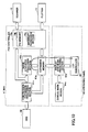
- Fig. 6 is a diagram showing a data flow for displaying a preview image at the same time as when image data are being stored.
- :image data read by the scanner 12 are sent to the compression/expansion processing section 41a and the image synthesis processing section 41b via the PCI controller 79a.
- the display synthesis processing section 82a forms a preview image (display data) by synthesizing the image data received from the expansion memory 67a in the IMH 41 with the picture image stored in the symbol mark region 84a.
- the LCD controller 85 displays the preview image (display data) on the LCD panel 90.
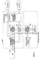
- Fig. 9 is a diagram showing a data flow for storing a preview image after processing image data.
- processed image data stored in the expansion memory 67a are compressed by the compression/expansion processing section 41a and the compressed image data are stored in the HDD 68.
- a staple button is pushed, a binding position of documents is clicked, and a staple position is designated.
- a staple button is pushed and the page turning direction is designated.
- a short stroke is suitable when a page is turned, and a page turning direction is suitable which easily turns a page.
- a relationship between a staple position and a page turning direction is described.
- the number written in each sheet 1, 2, 3, and 4 is the image order scanned by the scanner 12, for example, the number corresponds to the page number.
- the image order is referred to as the read image 1, 2, 3, ⁇ n.
- a staple position "sp" is shown by a bold line and a punch position “ph” is shown by "o”, and a page turning direction "d” is shown by an arrow.
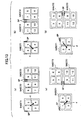
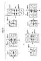
- Fig. 12 is a diagram showing a relationship between a staple position "sp" and a page turning direction “d" when the staple positions "sp" are two.
- Fig. 12(b) when the sheet 1 is turned, the sheets 2 and 3 are a two-page spread.
- the sheet 2 is a rear surface of the sheet 1.
- the staple positions "sp" are at the left sides of the read images 7 and 8 in the sheet 2 and at the right sides of the read images 9 and 10 in the sheet 3.
- Fig. 12(c) when the sheet 1 is turned, the sheets 2 and 3 are a two-page spread.
- the sheet 2 is a rear surface of the sheet 1.
- the staple positions "sp" are at the lower sides of the read images 7 and 8 in the sheet 2 and at the upper sides of the read images 9 and 10 in the sheet 3.
- Fig. 13 is a diagram showing a relationship between a staple position "sp" and a page turning direction “d” when the staple position "sp" is at the upper side.
- the staple is positioned along one side at the upper end of the sheet.
- Fig. 13(c) when the sheet 1 is turned, the sheets 2 and 3 are a two-page spread.
- the sheet 2 is a rear surface of the sheet 1.
- the staple position "sp" is at the lower left side of the read image 7 in the sheet 2 and at the upper left side of the read image 9 in the sheet 3.
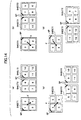
- Fig. 14 is a diagram showing a relationship between a staple position "sp" and a page turning direction “d” when the staple position "sp" is at a corner end.
- the long-length direction of the staple is positioned along one corner of the sheet.
- Fig. 14(d) when the sheet 1 is turned, the sheets 2 and 3 are a two-page spread.
- the sheet 2 is a rear surface of the sheet 1.
- the staple position "sp" is at the upper left corner of the read image 6 in the sheet 2 and at the upper right corner of the read image 9 in the sheet 3.
- Fig. 15(c) when the sheet 1 is turned, the sheets 2 and 3 are a two-page spread.
- the sheet 2 is a rear surface of the sheet 1.
- the punch position "ph" is at the lower sides of the read images 7 and 8 in the sheet 2 and at the upper sides of the read images 9 and 10 in the sheet 3.
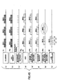
- Fig. 16 is a table 92 in which a binding method of a document and a page turning direction of the document are shown by correlating with each other.
- a user scans an image by setting a processing condition, displays a preview image, and prints the image and simultaneously stores the image.
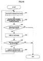
- Fig. 17 is a flowchart showing the processes to execute all the operations which can perform the above three patterns.
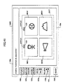
- Fig. 18 is a diagram showing a screen on which a preview image is displayed after reading a document.
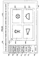
- a screen G100 displayed on the LCD panel 90 includes a message region 100a, a staple button 100b, a both-side printing button 100c, a document aggregation button 100d, a rotation button 170, an automatic page turning button 180, and a preview image displaying region 100e.
- a staple position is designated by the staple button 100b
- both-side printing is designated by the both-side printing button 100c
- aggregation of pages is designated by the document aggregation button 100d
- a preview image is rotated by the rotation button 170
- the status of all the pages of the document is shown by the automatic page turning button 180.
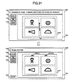
- Fig. 21 is a diagram showing processes for designating a staple position.
- a screen G101 shown in Fig. 21 when the staple button 100b is selected, plural staple marks STPL1, STPL2, STPL3, STPL4, STPL5, and STPL6 are shown on the sheet image SHT1.
- the user When the user satisfies the arrangement order shown by the button 114a, the user pushes the enter button 110f. However, when the user does not satisfy the arrangement order shown by the button 114a, the user can change the arrangement order by selecting one of the buttons 114b through 114d.
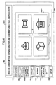
- Fig. 26 is a diagram showing a screen in which the sheet image SHT1 has been completely turned. As shown in Fig. 26, a screen G124 (preview screen) in which the sheet image SHT1 has been completely turned and the rear surface of the sheet image SHT1 (second page) is shown.
- Fig. 29 is a diagram showing processes for displaying a development view.
- the sheet image SHT1 is determined as the preview image for printing.
- a preview image shown in Fig. 38(a) or 38(b) in which the head and tail of the rear surface of the sheet image SHT1 are reversed is shown in a screen G228a or G228b.
- Fig. 38(a) on the screen G228a, the head and tail of each image in the SHT1 are reversed. That is, the head and tail of the images in the rear surface of the sheet image SHT1 are reversed.
- Fig. 38(b) on the screen G228b, the positions of the staple marks STPL21 and STPL22 are only reversed.
- the user finely adjusts the positions of the staple mark STPL21 and/or the staple mark STPL22, the user selects one of the buttons 420e, 420f, and 420g.
- the user pushes the button 420h.
- the staple position adjustment 410 includes a vertical adjustment button 410a for vertically adjusting the staple position and a horizontal adjustment button 410b for horizontally adjusting the staple position.
- Fig. 42 is a diagram showing a screen G403 in which the document image position is adjusted.
- the screen G403 shown in Fig. 42 is displayed.
- a message for example, "DOCUMENT IMAGE POSITION IS ADJUSTED, INPUT FIGURE" is displayed, and document image position adjustment 420 is displayed.
- the user adjusts the positions of the document images IMG1 through IMG4 by using the buttons 420a and 420b.
- the user pushes the enter button 220f.
- the image processing apparatus 1 again determines whether the staple position overlaps the document image IMG1 and/or IMG2. When the staple position overlaps the document image IMG1 and/or IMG2, the image processing apparatus 1 again displays the warning screen 420.
- the document image positions before adjustment are shown by broken line marks D1 through D4. Therefore, the user can use the buttons 420a and 420b by viewing the screen G403.
- the user reduces the sizes of the document images IMG1 through IMG4 by using the buttons 430a.
- the user pushes the enter button 220f.
- the image processing apparatus 1 again determines whether the staple position overlaps the document image IMG1 and/or IMG2. When the staple position overlaps the document image IMG1 and/or-IMG2, the image processing apparatus 1 again displays the warning screen 420.
- the sizes of the document images IMG1 through IMG4 before reduction are shown by broken line marks M1 through M4. Therefore, the user can use the button 430a by viewing the screen G404.
- the above staple position adjustment can be applied to punch position adjustment.
- the image processing apparatus 1 determines whether the binding position overlaps the image based on the searched result (S33). When the binding position does not overlap the image (NO in S33), the process ends.
- Fig. 49 is a timing chart for displaying a preview image when page turning is designated by a drag of a user. Referring to Fig. 49, an operation is described in which the page turning is designated by a drag of a user on the preview image displaying region 100e.
- signals of the document images IMG1, IMG2, and IMG3 read by the scanner 12 are instantly stored in the PCI memory 79b.
- Fig. 50 is a timing chart for displaying a preview image when automatic page turning is designated by a user. Referring to Fig. 50, an operation is described in which the automatic page turning:is designated by pushing the automatic page turning button 180 shown in Fig. 18 or an instruction on the image processing apparatus 1.
- signals of the document images IMG1, IMG2, IMG3, and IMG4 read by the scanner 12 are instantly stored in the PCI memory 79b.
- the interrupt processing section 79c generates an interrupt signal each time when the scanner 12 reads an image of one band having the predetermined number of lines.
- the HDD 68 stores the one band image based on an image transfer clock, and the image synthesis processing section 41b and the expansion memory 67a obtain the one band image based on the interrupt signal.
- the display synthesis processing section 82a synthesizes the one band images to form the document image IMG1; after synthesizing the one band images of the document image IMG1, the one band images of the document image IMG2 are synthesized. The above processes are continued to synthesize the one band images to form the document image IMG4.
- the LCD controller 85 displays the document image IMG1 in the order of band images L1, L2, L3, L4, and L5, after displaying the document image IMG1, the document image IMG2 is displayed. The above processes are continued to display the document image IMG4.
- the band images L1 through L5 are almost simultaneously displayed.
- the interrupt processing section 79c calculates interrupt timing from a reducing factor designated by a processing condition.
- a processing condition When the size of a document image is to be reduced, since the original document image is read from the HDD 68 by thinning (not reading all) data thereof, the reading speed is higher than the writing speed to the HDD 68. Therefore, the interrupt timing is determined by a predetermined algorithm with the consideration of the writing speed. For example, in a four document image aggregation, each document image, IMG1, IMG2, IMG3, or IMG4 is reduced to 1/4 size, and the reading speed is four times higher than the writing speed due to the thinning. Therefore, the interrupt timing is the time when 75% of the document image IMG1 is written in the HDD 68.
- the interrupt processing section 79c generates an interrupt signal at the calculated interrupt timing.
- the image synthesis processing section 41b sequentially reads the document images IMG1 through IMG4 based on the reading speed of the reducing factor while instantly storing the document images IMG1 through IMG4 in the expansion memory 67a.
- the interrupt processing section 79c calculates interrupt timing from a reducing factor designated by a processing condition.
- the calculation method of the interrupt timing is the same as that in the first displaying method described above.
- the interrupt processing section 79c generates an interrupt signal based on the calculated interrupt timing.
- the image synthesis processing section 41b sequentially reads the document images IMG1 through IMG4 based on the reading speed of the reducing factor of the four document image aggregation while instantly storing the document images IMG1 through IMG4 in the expansion memory 67a.
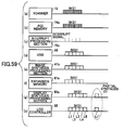
- Figs. 59 through 61 one staple mark is attached to the document image IMG1.
- Fig. 59 is a timing chart showing processes to attach a staple mark on a preview image of a document image.
- signals of the document image IMG1 read by the scanner 12 are instantly stored in the PCI memory 79b.
- the display synthesis processing section 82a synthesizes a part of the band image L1 where the staple is to be attached with a staple mark read from the symbol mark region 84a (partial synthesis 51) and rewrites the position of the staple mark on a part of the band image where the staple mark is already positioned. Then the new staple mark position is displayed.
- the LCD controller 85 displays the staple mark position at a position L1'.
- the present invention is based on Japanese Priority Patent Application No. 2006-073406, filed on March 16, 2006 , and Japanese Priority Patent Application No. 2007-060381, filed on March 9, 2007 , with the Japanese Patent Office, the entire contents of which are hereby incorporated herein by reference.
Landscapes
- Engineering & Computer Science (AREA)
- Multimedia (AREA)
- Signal Processing (AREA)
- Human Computer Interaction (AREA)
- Physics & Mathematics (AREA)
- General Physics & Mathematics (AREA)
- Microelectronics & Electronic Packaging (AREA)
- Control Or Security For Electrophotography (AREA)
- Facsimiles In General (AREA)
- Record Information Processing For Printing (AREA)
- Editing Of Facsimile Originals (AREA)
- Accessory Devices And Overall Control Thereof (AREA)
Abstract
Description
- The present invention generally relates to an image processing apparatus and a preview image displaying method in the image processing apparatus which allows operability close to human senses.
- Recently, in an image processing apparatus having a copying function, a scanning function, and so on, a method is proposed in which a processing condition by a user is easily determined when an image is formed by using the above function.
- For example, in
Patent document 1, an image processing apparatus is disclosed. In the image processing apparatus, an image is pre-scanned by selecting a reading condition in a scanner and a reading condition having a high recognition rate is automatically selected by applying an OCR (optical character recognition) process to the pre-scanned image. With this, the processing condition is easily determined by the user. - In addition, in
Patent Document 2, a scanner and a control method thereof are disclosed. In the scanner, a preview image pre-scanned by a user is rotated corresponding to necessity, and the user scans the image by setting a suitable rotational angle. - [Patent Document 1]
Japanese Laid-Open Patent Application No. 2004-234261 - [Patent Document 2]
Japanese Laid-Open Patent Application No. 2001-045239 - However, when a user copies images (documents) by setting processing conditions such as both-side printing, aggregation of pages, and stapling sheets; an output document may be different from that the user desires to obtain. Consequently, the user tries a copy of the images by setting processing conditions, and confirms the copied document. Then, the user changes the processing conditions, if necessary.
- In some cases, corresponding to the settings of the processing conditions, documents are stapled, and a thumbnail image of the staple documents is displayed. However, the stapled image is displayed in a fixed small image from which the stapled status is hardly recognized.
- Consequently, the user cannot recognize whether the documents are stapled by the set processing conditions before the document is actually printed.
- That is, in the conventional method, a visually recognition method of the status to be output and a changing method of settings are not provided. Therefore, the user cannot easily determine the settings of the processing conditions visually and intuitively before an image is output.
- In a preferred embodiment of the present invention, there is provided an image processing apparatus and a preview image displaying method in the image processing apparatus which allows operability close to human senses.
- Features and advantages of the present invention are set forth in the description that follows, and in part will become apparent from the description and the accompanying drawings, or may be learned by practice of the invention according to the teachings provided in the description. Features and advantages of the present invention will be realized and attained by an image processing apparatus and a preview image displaying method in the image processing apparatus particularly pointed out in the specification in such full, clear, concise, and exact terms as to enable a person having ordinary skill in the art to practice the invention.
- To achieve one or more of these and other advantages, according to one aspect of the present invention, there is provided an image processing apparatus which previews a read image. The image processing apparatus includes a preview image processing unit in which a user is allowed to set a processing condition for the read preview image by operating on the read preview image and a preview image processed by the processing condition is displayed together with the setting of the processing condition on a displaying section.
- According to an embodiment of the present invention, a user can set a processing condition for printing an image by directly operating a preview image. In addition, the processing condition can be set by a click and a drag on the preview image. Therefore, the user can visually and intuitively set the processing condition.
- Moreover, the user can designate a staple position by touching a desirable position on the preview image. In addition, operability of the user can be increased by operation buttons and an operation on the preview image.
- Features and advantages of the present invention will become more apparent from the following detailed description when read in conjunction with the accompanying drawings, in which:
- Fig. 1 is a block diagram showing functions of an image processing apparatus according to an embodiment of the present invention;
- Fig. 2 is a block diagram showing hardware of the image processing apparatus;
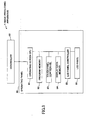
- Fig. 3 is a block diagram showing an operating panel in detail in the image processing apparatus;
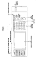
- Fig. 4 is a diagram showing an upper surface of the operating panel;
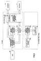
- Fig. 5 is a diagram showing an IMH and the operating panel for synthesizing moving images;
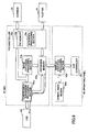
- Fig. 6 is a diagram showing a data flow for displaying a preview image at the same time as when image data are stored;
- Fig. 7 is a diagram showing a data flow for displaying a preview image when a processing condition is designated after storing image data;
- Fig. 8 is a diagram showing a data flow for printing a preview image after processing image data;
- Fig. 9 is a diagram showing a data flow for storing a preview image after processing image data;
- Fig. 10 is a diagram showing a data flow for displaying a preview image when a new processing condition is set in the image data stored in an expansion memory;
- Fig. 11 is a diagram showing a data flow for displaying a preview image by using an initial processing condition;
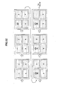
- Fig. 12 is a diagram showing a relationship between a staple position and a page turning direction when the staple positions are two;
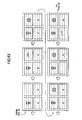
- Fig. 13 is a diagram showing a relationship between a staple position and a page turning direction when the staple position is at the upper side;
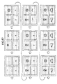
- Fig. 14 is a diagram showing a relationship between a staple position and a page turning direction when the staple position is at a corner end;
- Fig. 15 is a diagram showing a relationship between a punch position and a page turning direction;
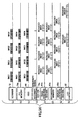
- Fig. 16 is a table in which a binding method of a document and a page turning direction of the document are shown by correlating with each other;
- Fig. 17 is a flowchart showing processes to execute all the operations which can perform three patterns;
- Fig. 18 is a diagram showing a screen on which a preview image is displayed after reading a document;
- Fig. 19 is a diagram showing a screen on which a rotated preview image is displayed by pushing a rotation button shown in Fig. 18;
- Fig. 20A is a diagram showing a screen on which a preview image is displayed by pushing an automatic page turning button shown in Fig. 18;
- Fig. 20B is a diagram showing a screen on which a preview image on a page is displayed by pushing a start button shown in Fig. 20A;
- Fig. 21 is a diagram showing processes for designating a staple position;
- Fig. 22 is a diagram showing processes for designating a document aggregation;
- Fig. 23 is a diagram showing a screen of a preview image in which both-side printing is designated;
- Fig. 24 is a diagram showing page turning directions;
- Fig. 25 is a diagram showing screens in which documents are turned;
- Fig. 26 is a diagram showing a screen in which a first sheet image has been completely turned;:
- Fig. 27 is a diagram showing a screen in which a process returning to previous pages is shown; Fig. 28 is a diagram showing a screen in which a;second sheet image is shown;
- Fig. 29 is a diagram showing processes for displaying a development view;
- Fig. 30 is a diagram showing a screen in which the head and tail of the rear surface of the first sheet image is changed;
- Fig. 31 is a diagram showing screens of a preview image in which a staple position is determined by designating the page turning direction;
- Fig. 32 is a diagram showing processes for designating the page turning direction;
- Fig. 33 is a diagram showing screens in which the first sheet image is turned;
- Fig. 34 is a diagram showing a screen in which the rear surface of the first sheet image (second page) is displayed;
- Fig. 35 is a diagram showing a screen in which a process returning to previous pages is shown; Fig. 36 is a diagram showing a screen in which the second sheet image is shown;
- Fig. 37 is a diagram showing processes to display a development view;
- Fig. 38 is a diagram showing screens in which the head and tail of the rear surface of the first sheet image are reversed;
- Fig. 39 is a diagram showing processes (screen flow) in which a processing condition is determined before reading a document;
- Fig. 40 is a diagram showing processes (screen flow) for adjusting a staple position;
- Fig. 41 is a diagram showing a screen in which the staple position is adjusted;
- Fig. 42 is a diagram showing a screen in which a document image position is adjusted;
- Fig. 43 is a diagram showing a screen in which a document image is reduced;
- Fig. 44 is a flowchart showing processes to adjust an overlap position where a binding position of documents overlaps an image;
- Fig. 45 is a timing chart of a normal operation for displaying a preview image;
- Fig. 46 is a diagram showing a flow for displaying a preview image in the normal operation;
- Fig. 47 is a timing chart for displaying a preview image when a rotation method is designated in a processing condition;
- Fig. 48 is a diagram showing first document images when the image is read and displayed by being applied a rotation method;
- Fig. 49 is a timing chart for displaying a preview image when page turning is designated by a drag of a user;
- Fig. 50 is a timing chart for displaying a preview:image when automatic page turning is designated by a user;
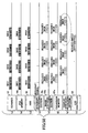
- Fig. 51 is a first timing chart in which a preview image is displayed by aggregating four document images into one page;
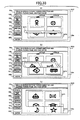
- Fig. 52 is a diagram showing a first screen flow in which a preview image having four reduced document images is displayed;
- Fig. 53 is a diagram showing a second screen flow in which a preview image having the four reduced document images is displayed;
- Fig. 54 is a diagram showing a third screen flow in which a preview image having the four reduced document images is displayed;
- Fig. 55 is a diagram showing a fourth screen flow in which a preview image having the four reduced document images is displayed;
- Fig. 56 is a second timing chart in which a preview image is displayed by aggregating four document images into one page;
- Fig. 57 is a diagram showing a screen flow in which a preview image having the four reduced document images is displayed based on the second timing chart;
- Fig. 58 is a third timing chart in which a preview image is displayed by aggregating two document images into one page;
- Fig. 59 is a timing chart showing processes to attach a staple mark on a preview image of a document image;
- Fig. 60 is a screen flow when a staple mark is attached to a preview image; and
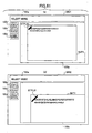
- Fig. 61 is a diagram showing screens of preview images in which the staple position is determined.
- Exemplary embodiments of the present invention are now described with reference to the accompanying drawings.
- Fig. 1 is a block diagram showing functions of an image processing apparatus according to an embodiment of the present invention. As shown in Fig. 1, an
image processing apparatus 1 includes asoftware group 2, ahardware resource 4, and anoperating panel 80. In theimage processing apparatus 1 shown in Fig. 1, in order to make the description concise, only elements necessary for the present invention are shown. - The
software group 2 includes various functions to be realized by programs which are executed by a CPU (central processing unit) 61 (described below) in a controller 60 (described below). Thehardware resource 4 includes aplotter 11, ascanner 12, and so on. The operatingpanel 80 receives an instruction from a user and displays information for the user. - The
software group 2 includes anapplication layer 5 and aplatform layer 6. An OS (operating system) on theapplication layer 5 and theplatform layer 6 executes software in theapplication layer 5 and theplatform layer 6 in parallel. - The
application layer 5 includes, for example,copy application software 22 for supplying a copy function to a user. Theapplication layer 5 can include other application software. - The
platform layer 6 manages the use of thehardware resource 4 by interpreting a process request from theapplication layer 5. Theplatform layer 6 includes an MCS (memory control service) 36 and an IMH (image memory handler) 41. TheMCS 36 obtains a memory region and releases the obtained memory region, utilizes an HDD (described below), controls compressing image data and expanding the compressed image data, and controls other functions. TheIMH 41 manages a memory. - When the
copy application software 22 requests theMCS 36 to obtain an image for previewing the image, theMCS 36 requests theIMH 41 to obtain an image read by thescanner 12. When thescanner 12 obtains an image requested by theIMH 41, thescanner 12 informs theIMH 41 of obtaining the image. TheIMH 41 informs theMCS 36 of obtaining the image. TheMCS 36 informs thecopy application software 22 of obtaining the image. Thecopy application software 22 communicates with the operatingpanel 80 so that the obtained image is previewed. - The preview image is displayed on the
operating panel 80, and a user performs a desirable operation on the preview image on theoperating panel 80. When processing conditions are determined by a user operation, thecopy application software 22 receives the processing conditions from the operatingpanel 80 and makes theIMH 41 execute a process on the image read by thescanner 12 via theMCS 36. TheIMH 41 makes theplotter 11 form an image on a predetermined recording medium on which image the process is to be applied. - Fig. 2 is a block diagram showing hardware of the
image processing apparatus 1. As shown in Fig. 2, theimage processing apparatus 1 includes thecontroller 60, the operatingpanel 80, theplotter 11 and thescanner 12. - As shown in Fig. 2, the
controller 60 includes theCPU 61, asystem memory 62, an NB (north bridge) 63, an ASIC (application specific integrated circuit) 66, alocal memory 67, a HDD (hard disk drive) 68, and anexternal interface 70. - The operating
panel 80 is connected to theASIC 66. Theplotter 11 and thescanner 12 are connected to theASIC 66 via a PCI (peripheral component interconnect)bus 79. - The
local memory 67 and theHDD 68 are connected to theASIC 66, and theCPU 61 is connected to theASIC 66 via theNB 63 which is a CPU chip set. TheASIC 66 is connected to theNB 63 via an AGP (accelerated graphic port) 65. - The
CPU 61 controls all the elements in theimage processing apparatus 1. TheCPU 61 operates theMCS 36 and theIMH 41 on the OS, and operates thecopy application software 22 in theapplication layer 5. - The
NB 63 connects theCPU 61 to thesystem memory 62, theASIC 66, and theexternal interface 70. TheNB 63 is connected to theexternal interface 70 via aPCI bus 73. - The
system memory 62 stores image data for writing. Thelocal memory 67 is a buffer for storing image data for copying and for storing code data. TheASIC 66 is an image processing IC having hardware elements. TheHDD 68 is storage for storing image data, document data, programs, font data, form data, and so on. - The
external interface 70 connects theimage processing apparatus 1 to a network such as the Internet and a LAN. - Fig. 3 is a block diagram showing the operating
panel 80 in detail in theimage processing apparatus 1. As shown in Fig. 3, the operatingpanel 80 includes anoperating screen CPU 81, aprogram memory 82, atouch panel controller 83, adisplay data memory 84, a LCD (liquid crystal display)panel controller 85, and anLCD panel 90. - The
operating screen CPU 81 controls all the elements in theoperating panel 80 by communicating with thecontroller 60. In addition, theoperating screen CPU 81 controls a display on theLCD panel 90 by reading a program stored in theprogram memory 82 and executing the program. - The
program memory 82 stores all the programs for controlling all the elements in theoperating panel 80. Thetouch panel controller 83 controls theLCD panel 90 corresponding to a user operation on a screen displayed on theLCD panel 90 via the:LCD panel controller 85. Thedisplay data memory 84 stores image data which are used for displaying a preview image. TheLCD panel controller 85 controls a display on theLCD panel 90 corresponding to the user operation. TheLCD panel 90 provides a touch panel function. - Fig. 4 is a diagram showing an outline of the operating
panel 80. As shown in Fig. 4, the operatingpanel 80 includes aliquid crystal panel 8, afunction selecting button 8a, anoperating button 8b, ten-key buttons 8c,buttons 8d, astart button 8e, and apower switch 8f. - A preview image (described below) is displayed on the
liquid crystal panel 8. Thefunction selecting button 8a includes a copy button, a document button, a facsimile button, a printer button, and a scanner button; and one of the buttons is selected by a user. Theoperating button 8b includes a program button, a reset button, and a preheat button. - From the ten-
key button 8c, the user inputs a figure. Thebutton 8d includes a trial copy button and clear/stop buttons for cancelling the operation. The user starts operations by pushing thestart button 8e. The power of theimage processing apparatus 1 is turned on by pushing thepower switch 8f. - Next, referring to Figs. 1 through 9, the
IMH 41 and theoperating panel 80 for displaying a preview image are described in detail. - Fig. 5 is a diagram showing the
IMH 41 and theoperating panel 80 for synthesizing moving images. As shown in Fig. 5, theIMH 41 includes a compression/expansion processing section 41a, an imagesynthesis processing section 41b, anexpansion memory 67a, and aPCI controller 79a. - The compression/
expansion processing section 41a compresses image data stored in theexpansion memory 67a and image data read by thescanner 12 when the image data are stored in theHDD 68. In addition, the compression/expansion processing section 41a expands the image data stored in theHDD 68 when the image data are processed by theplotter 11 or are stored in theexpansion memory 67a. - The image
synthesis processing section 41b synthesizes image data read by thescanner 12 by storing the image data in theexpansion memory 67a based on an initial processing condition, and synthesizes image data stored in theexpansion memory 67a based on a set processing condition. The synthesized image data are output by theplotter 11 as print data. - The
expansion memory 67a is a part of thelocal memory 67 which can be used by theIMH 41 and stores processed image data. - The
PCI controller 79a includes aPCI memory 79b and an interruptprocessing section 79c and controls access to thescanner 12 and theplotter 11 vi the PCI bus 79 (refer to Fig. 2). ThePCI memory 79b temporarily stores image data read by thescanner 12 and image data for an image to be formed by theplotter 11. - The interrupt
processing section 79c generates an interrupt signal corresponding to timing when the imagesynthesis processing section 41b forms an image. Since thescanner 12 reads image data line by line, when the interruption signal is generated every one line reading, a preview image is formed by synthesizing line images and one line image is sequentially displayed. In addition, when the preview image is displayed by-rotating the image, the number of image transfer clocks generated by thescanner 12 at each one line reading is counted and the interrupt signal is generated when the counted number equals clocks for the lines of one page. - As shown in Fig. 5, the operating
panel 80 includes a displaysynthesis processing section 82a, asymbol mark region 84a, and anLCD controller 85. - The display
synthesis processing section 82a is realized when theoperating screen CPU 81 executes a program stored in theprogram memory 82, and synthesizes a symbol mark stored in thesymbol mark region 84a with image data fromexpansion memory 67a to form a preview iamge. - The
symbol mark region 84a is a part of thedisplay data memory 84 and stores picture images such as a staple mark and a punch mark beforehand. TheLCD controller 85 displays a synthesized preview image and also displays a screen based on an instruction by the user on theLCD panel 90. - Fig. 6 is a diagram showing a data flow for displaying a preview image at the same time as when image data are being stored. In Fig. 6, in the
IMH 41,:image data read by thescanner 12 are sent to the compression/expansion processing section 41a and the imagesynthesis processing section 41b via thePCI controller 79a. - The compression/
expansion processing section 41a compresses the received image data and stores the compressed image data in theHDD 68. The imagesynthesis processing section 41b synthesizes the received image data and stores the synthesized image data in theexpansion memory 67a. - In the
operating panel 80, the displaysynthesis processing section 82a forms a preview image (display data) by synthesizing the image data received from theexpansion memory 67a in theIMH 41 with the picture image stored in thesymbol mark region 84a. TheLCD controller 85 displays the preview image (display data) on theLCD panel 90. - Fig. 7 is a diagram showing a data flow for displaying a preview image when a processing condition is designated after storing image data. In Fig. 7, when a user designates a processing condition for image data stored in the
HDD 68, in theIMH 41, the compression/expansion processing section 41a expands image data read from theHDD 68, and the imagesynthesis processing section 41b synthesizes the expanded image data by the designated processing condition and stores the synthesized image data in theexpansion memory 67a. - In the
operating panel 80, the displaysynthesis processing section 82a forms a preview image (display data) by synthesizing the image data received from theexpansion memory 67a in theIMH 41 with the picture image stored in thesymbol mark region 84a. TheLCD controller 85 displays the preview image (display data) on theLCD panel 90. - Fig. 8 is a diagram showing a data flow for printing a preview image after processing image data. In Fig. 8, in the
IMH 41, processed image data stored in theexpansion memory 67a are sent to theplotter 11 via thePCI controller 79a, and theplotter 11 forms (prints) a preview image on a predetermined recording medium. - Fig. 9 is a diagram showing a data flow for storing a preview image after processing image data. In Fig. 9, in the
IMH 41, processed image data stored in theexpansion memory 67a are compressed by the compression/expansion processing section 41a and the compressed image data are stored in theHDD 68. - Fig. 10 is a diagram showing a data flow for displaying a preview image when a new processing condition is set in the image data stored in the
expansion memory 67a. In Fig. 10, when a user designates a new processing condition for the image data stored in theexpansion memory 67a, the imagesynthesis processing section 41b reads image data from theexpansion memory 67a without reading image data from theHDD 68, synthesizes the read image data, and stores the image data in theexpansion memory 67a. - ' In the
operating panel 80, the displaysynthesis processing section 82a forms a preview image (display data) by synthesizing the image data received from theexpansion memory 67a in theIMH 41 with the picture image stored in thesymbol mark region 84a. TheLCD controller 85 displays the preview image (display data) on theLCD panel 90. - In this case, a process is not needed in which the compression/
expansion processing section 41a expands image data by reading the image data from theHDD 68. Therefore, the memory resources can be effectively used and the power consumption can be reduced. - Fig. 11 is a diagram showing a data flow for displaying a preview image by using an initial processing condition. In Fig. 11, when a determined processing condition is cancelled and a processing condition is made to be an initial processing condition, in the
IMH 41, the compression/expansion processing section 41a expands image data read from theHDD 68, and the imagesynthesis processing section 41b synthesizes the expanded image data by the initial processing condition and stores the synthesized image data in theexpansion memory 67a. - In the
operating panel 80, the displaysynthesis processing section 82a forms a preview image (display data) by synthesizing the image data received from theexpansion memory 67a in theIMH 41 with a picture image stored in thesymbol mark region 84a. TheLCD controller 85 displays the preview image (display data) on theLCD panel 90. - In the embodiment of the present invention, in order to easily determine a processing condition for printing an image by directly operating a preview image displayed on the
operating panel 80, the following method is established which method designates a processing condition based on user psychology. - (1). A staple button is pushed, a binding position of documents is clicked, and a staple position is designated.
- (2). A page is turned, a finishing state of a document is confirmed, and a staple position of the document is designated.
- (3). When the head and tail of a stapled document are wrong, a staple position of the document is designated by changing the head and tail.
- (1). A staple button is pushed and the page turning direction is designated.
- (2). A staple position and the head and tail of a document are set in an image processing apparatus corresponding to the page turning direction.
- (3). When the head and tail of a stapled document are wrong; the head and tail of the rear surface is changed by changing the head and tail of the front surface.
- (1). Horizontal wiring may be largely used in a business document.
- (2). The staple position is suitable at the upper side or the left side of the business document.
- (3). When some documents are aggregated in one sheet, the staple position may be at the side of the sheet having a small page number.
- (4). The page turning direction is determined by the staple position.
- (5). A short stroke is suitable when a page is turned, and a page turning direction is suitable which easily turns a page.
- A punch position is similar to the above staple position.
- There is an exception to the user psychology; therefore, in the embodiment of the present invention, candidates for providing the user with easy operations are determined, and the user can select one of the candidates.
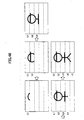
- Referring to Figs. 12 through 16, a relationship between a staple position and a page turning direction is described. In Figs. 12 through 16, an example in which four pages are aggregated in one sheet is described. The number written in each
sheet scanner 12, for example, the number corresponds to the page number. The image order is referred to as theread image - Fig. 12 is a diagram showing a relationship between a staple position "sp" and a page turning direction "d" when the staple positions "sp" are two.
- In Fig. 12(a), in
vertical direction sheets read images image 2 to the read image 1 (theread image 4 to the read image 3). On the other hand, when the page turning direction "d" is designated from the readimage 1 to the read image 2 (theread image 3 to the read image 4), the staple positions "sp" are predicted at the right sides of theread images - In Fig. 12(a), when the
sheet 1 is turned, thesheets sheet 2 is a rear surface of thesheet 1. The staple positions "sp" are at the right sides of theread images sheet 2 and at the left sides of theread images sheet 3. - In Fig. 12(b), in
vertical direction sheets read images image 3 to the read image 1 (theread image 4 to the read image 2). On the other hand, when the page turning direction "d" is designated from the readimage 1 to the read image 3 (theread image 2 to the read image 4), the staple positions "sp" are predicted at the left sides of theread images - In Fig. 12(b), when the
sheet 1 is turned, thesheets sheet 2 is a rear surface of thesheet 1. The staple positions "sp" are at the left sides of theread images sheet 2 and at the right sides of theread images sheet 3. - In Fig. 12(c), in
horizontal direction sheets read images image 3 to the read image 1 (theread image 4 to the read image 2). On the other hand, when the page turning direction "d" is designated from the readimage 1 to the read image 3 (theread image 2 to the read image 4), the staple positions "sp" are predicted at the lower sides of theread images - In Fig. 12(c), when the
sheet 1 is turned, thesheets sheet 2 is a rear surface of thesheet 1. The staple positions "sp" are at the lower sides of theread images sheet 2 and at the upper sides of theread images sheet 3. - In Fig. 12(d), in
horizontal direction sheets read images image 2 to the read image 1 (theread image 4 to the read image 3). On the other hand, when the page turning direction "d" is designated from the readimage 1 to the read image 2 (theread image 3 to the read image 4), the staple positions "sp" are predicted at the lower sides of theread images - In Fig. 12(d), when the
sheet 1 is turned, thesheets sheet 2 is a rear surface of thesheet 1. The staple positions "sp" are at the lower sides of theread images sheet 2 and at the upper sides of theread images sheet 3. - Fig. 13 is a diagram showing a relationship between a staple position "sp" and a page turning direction "d" when the staple position "sp" is at the upper side. In Fig. 13, the staple is positioned along one side at the upper end of the sheet.
- In Fig. 13(a), in
vertical direction sheets image 1 along the side, the page turning direction "d" is predicted from the readimage 4 to the readimage 1. On the other hand, when the page turning direction "d" is designated from the readimage 1 to the readimage 4, the staple position "sp" is predicted at the lower right side of the readimage 4. - In Fig. 13(a), when the
sheet 1 is turned, thesheets sheet 2 is a rear surface of thesheet 1. The staple position "sp" is at the upper right side of the readimage 6 in thesheet 2 and at the upper left side of the readimage 9 in thesheet 3. - In Fig. 13(b), in
vertical direction sheets image 1 along the side, the page turning direction "d" is predicted from the readimage 4 to the readimage 1. On the other hand, when the page turning direction "d" is designated from the readimage 1 to the readimage 4, the staple position "sp" is predicted at the lower left side of the readimage 4. - In Fig. 13(b), when the
sheet 1 is turned, thesheets sheet 2 is a rear surface of thesheet 1. The staple position "sp" is at the upper left side of the readimage 7 in thesheet 2 and at the upper right side of the readimage 9 in thesheet 3. - In Fig. 13(c), in
horizontal direction sheets image 1 along the upper side, the page turning direction "d" is predicted from the readimage 4 to the readimage 1. On the other hand, when the page turning direction "d" is designated from the readimage 1 to the readimage 4, the staple position "sp" is predicted at the lower right side of the readimage 4 along the lower side. - In Fig. 13(c), when the
sheet 1 is turned, thesheets sheet 2 is a rear surface of thesheet 1. The staple position "sp" is at the lower left side of the readimage 7 in thesheet 2 and at the upper left side of the readimage 9 in thesheet 3. - In Fig. 13(d), in
horizontal direction sheets image 1 along the upper side, the page turning direction "d" is predicted from the readimage 4 to the readimage 1. On the other hand, when the page turning direction "d" is designated from the readimage 1 to the readimage 4, the staple position "sp" is predicted at the lower left side of the readimage 4 along the lower side. - In Fig. 13(d), when the
sheet 1 is turned, thesheets sheet 2 is a rear surface of thesheet 1. The staple position "sp" is at the lower right side of the readimage 6 in thesheet 2 and at the upper right side of the readimage 9 in thesheet 3. - Fig. 14 is a diagram showing a relationship between a staple position "sp" and a page turning direction "d" when the staple position "sp" is at a corner end. In Fig. 14, the long-length direction of the staple is positioned along one corner of the sheet.
- In Fig. 14(a), in
vertical direction sheets image 1, the page turning direction "d" is predicted from the readimage 4 to the readimage 1. On the other hand, when the page turning direction "d" is designated from the readimage 1 to the readimage 4, the staple position "sp" is predicted at the lower right corner of the readimage 4. - In Fig. 14(a), when the
sheet 1 is turned, thesheets sheet 2 is a rear surface of thesheet 1. The staple position "sp" is at the upper right corner of the readimage 6 in thesheet 2 and at the upper left corner of the readimage 9 in thesheet 3. - In Fig. 14(b), in
vertical direction sheets image 1, the page turning direction "d" is predicted from the readimage 4 to the readimage 1. On the other hand, when the page turning direction "d" is designated from the readimage 1 to the readimage 4, the staple position "sp" is predicted at the lower left corner of the readimage 4. - In Fig. 14(b), when the
sheet 1 is turned, thesheets sheet 2 is a rear surface of thesheet 1. The staple position "sp" is at the upper left corner of the readimage 7 in thesheet 2 and at the upper right corner of the readimage 9 in thesheet 3. - In Fig. 14(c), in
horizontal direction sheets image 1, the page turning direction "d" is predicted from the readimage 4 to the readimage 1. On the other hand, when the page turning direction "d" is designated from the readimage 1 to the readimage 4, the staple position "sp" is predicted at the lower right corner of the readimage 4. - In Fig. 14(c), when the
sheet 1 is turned, thesheets sheet 2 is a rear surface of thesheet 1. The staple position "sp" is at the upper right corner of the readimage 6 in thesheet 2 and at the upper left corner of the readimage 9 in thesheet 3. - In Fig. 14(d), in
horizontal direction sheets image 1, the page turning direction "d" is predicted from the readimage 4 to the readimage 1. On the other hand, when the page turning direction "d" is designated from the readimage 1 to the readimage 4, the staple position "sp" is predicted at the lower left corner of the readimage 4. - In Fig. 14(d), when the
sheet 1 is turned, thesheets sheet 2 is a rear surface of thesheet 1. The staple position "sp" is at the upper left corner of the readimage 6 in thesheet 2 and at the upper right corner of the readimage 9 in thesheet 3. - Next, a relationship between a punch position "ph" and a page turning direction "d" is described.
- Fig. 15 is a diagram showing the relationship between the punch position "ph" and the page turning direction "d".
- In Fig. 15(a), in
vertical direction sheets read images image 2 to the read image 1 (theread image 4 to the read image 3). On the other hand, when the page turning direction "d" is designated from the readimage 1 to the read image 2 (theread image 3 to the read image 4), the punch position "ph" is predicted at the right sides of theread images - In Fig. 15(a), when the
sheet 1 is turned, thesheets sheet 2 is a rear surface of thesheet 1. The punch position "ph" is at the right sides of theread images sheet 2 and at the left sides of theread images sheet 3. - In Fig. 15(b), in
vertical direction sheets read images image 2 to the read image 1 (theread image 4 to the read image 3). On the other hand, when the page turning direction "d" is designated from the readimage 1 to the read image 2 (theread image 3 to the read image 4), the punch position "sp" is predicted at the lower sides of theread images - In Fig. 15(b), when the
sheet 1 is turned, thesheets sheet 2 is a rear surface of thesheet 1. The punch position "ph" is at the lower sides of theread images sheet 2 and at the upper sides of theread images sheet 3. - In Fig. 15(c), in
horizontal direction sheets read images image 3 to the read image 1 (theread image 4 to the read image 2). On the other hand, when the page turning direction "d" is designated from the readimage 1 to the read image 3 (theread image 2 to the read image 4), the punch position "ph" is predicted at the lower sides of theread images - In Fig. 15(c), when the
sheet 1 is turned, thesheets sheet 2 is a rear surface of thesheet 1. The punch position "ph" is at the lower sides of theread images sheet 2 and at the upper sides of theread images sheet 3. - In Fig. 15(d), in
vertical direction sheets read images image 3 to the read image 1 (theread image 4 to the read image 2). On the other hand, when the page turning direction "d" is designated from the readimage 1 to the read image 3 (theread image 2 to the read image 4), the punch position "ph" is predicted at the left sides of theread images - In Fig. 15(d), when the
sheet 1 is turned, thesheets sheet 2 is a rear surface of thesheet 1. The punch position "ph" is at the left sides of theread images sheet 2 and at the right sides of theread images sheet 3. - Fig. 16 is a table 92 in which a binding method of a document and a page turning direction of the document are shown by correlating with each other.
- The
image processing apparatus 1 forms the table 92 shown in Fig. 16 based on methods similar to those shown in Figs. 12 through 15 and stores the table 92 in theHDD 68. - In the binding method of the document, items of 2-position stapling, 1-position stapling, and punching are shown, and each item has a position and a rear surface direction for a front surface. In the page turning direction, items of left direction turning, right direction turning, and upper direction turning are shown, and each item has horizontal writing and vertical writing.
- Further, in the position, a left side, a right side, and an upper side are shown. In the rear surface direction for front surface, the same direction and the head and tail reversed direction are shown.
- Next, user patterns are described.
- The following patters are estimated about user operations.
- In
pattern 1, a user scans an image, stores the scanned image, and processes the image. - In
pattern 2, a user scans an image by setting a processing condition, displays a preview image, and prints the image and simultaneously stores the image. - In
pattern 3, a user scans an image by setting a processing condition, displays a preview image, processes the image, and prints the image-and simultaneously stores the image. - Next, processes to execute all the operations which can perform the above three patterns are described.
- Fig. 17 is a flowchart showing the processes to execute all the operations which can perform the above three patterns.
- Referring to Fig. 17, the processes are described. First, the
image processing apparatus 1 determines whether a processing condition is designated by a user instruction (S11). When theimage processing apparatus 1 determines that the processing condition is designated by the user (YES in S11), the user designates the processing condition (S12). When theimage processing apparatus 1 does not determine that the processing condition is designated by the user (NO in S11), the process goes to S13. - Then, the
image processing apparatus 1 reads a document by the scanner 12 (S13), and forms an image by synthesizing line images (S14). In the image synthesis, images in each line or in one page are sequentially synthesized to form a preview image by the designated processing condition. The synthesis of one line image and the one page image are automatically switched based on the designated processing condition (described below). - Next, a preview image is displayed on the operating panel 80 (S15). Then it is determined whether the user instructs to print the preview image (S16). When it is determined that the user instructs to print the preview image (YES in S16), the
image processing apparatus 1 prints the preview image by the plotter 11 (S16-2). - When the user does not instruct to print the preview image (NO in S16), it is determined whether the user instructs to apply a process to the preview image (S17). When it is determined that the user instructs to apply a process to the preview image (YES in S17), the
image processing apparatus 1 makes the user designate a processing condition and applies the process to the preview image based on the processing condition (S18) and the process returns to S14. - Next, referring to Figs. 18 through 30, screens for designating a staple position on a document are described.
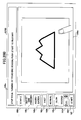
- Fig. 18 is a diagram showing a screen on which a preview image is displayed after reading a document. As shown in Fig. 18, a screen G100 displayed on the
LCD panel 90 includes amessage region 100a, astaple button 100b, a both-side printing button 100c, adocument aggregation button 100d, arotation button 170, an automaticpage turning button 180, and a previewimage displaying region 100e. A staple position is designated by thestaple button 100b, both-side printing is designated by the both-side printing button 100c, aggregation of pages is designated by thedocument aggregation button 100d, a preview image is rotated by therotation button 170, and the status of all the pages of the document is shown by the automaticpage turning button 180. - When a preview image is displayed after reading a document, a first document image IMG1 is displayed on a sheet image SHT1 in the preview
image displaying region 100e, and a message, for example, "SELECT MODE" for instructing a user to operate is displayed on themessage region 100a. In order to select a mode, the user pushes, for example, thestaple button 100b and designates the staple position. - In addition to the automatic
page turning button 180, a scroll bar can be disposed at the right side of the previewimage displaying region 100e. With this, the user can view pages by using the scroll bar. - In the following, main buttons for executing the embodiment of the present invention are shown, and other buttons may be omitted.
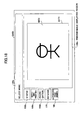
- Fig. 19 is a diagram showing the screen G100 on which a rotated preview image is displayed by pushing the
rotation button 170 shown in Fig. 18. - When the user pushes the
rotation button 170 shown in Fig. 18 on the screen G100, as shown in Fig. 19, a rotationmethod selecting button 172 is displayed. The rotationmethod selecting button 172 includes a head andtail reversing button 172a, a rightdirection rotation button 172b, a leftdirection rotation button 172c, anangle designation region 172d, and an OK button for determining the rotation angle. - The user can change the head and tail of the sheet image SHT1 by operating the head and
tail reversing button 172a. In addition, the user can rotate the sheet image SHT1 clockwise on a 90 ° basis by operating the rightdirection rotation button 172b, and can rotate the sheet image SHT1 counterclockwise on a 90 ° basis by operating the leftdirection rotation button 172c. Further, the user can designate the rotation angle by selecting one of 90 °, 180 °, 270 °, 360 ° (0 °) by operating an up and down button in theangle designation region 172d. When the rotation angle is determined, the user pushes the "OK"button 172f. Then the user executes a next process. - Fig. 20A is a diagram showing the screen G100 on which a preview image is displayed by pushing the automatic
page turning button 180 shown in Fig. 18. - When the user pushes the automatic
page turning button 180 shown in Fig. 18 on the screen G100, as shown in Fig. 20A, a page turningspeed selecting button 182 is displayed. The page turningspeed selecting button 182 includes afast button 182a, anormal button 182b, aslow button 182c, a page turningspeed designating region 182d, and a start button for starting the page turning with the designated speed. - The user can select fast speed by operating the
fast button 182a, can select normal speed by operating thenormal button 182b, and can select slow speed by operating theslow button 182c. - In addition, the user can change the speed by operating an up and down button in the page turning
speed designating region 182d. When the page turning speed is determined, the user pushes thestart button 182f. With this, preview images are sequentially displayed at the selected speed on the previewimage displaying region 100e in the order of the pages of the document read by thescanner 12. - Fig. 20B is a diagram showing the screen G100 on which a preview image on a page is displayed by pushing the
start button 182f shown in Fig. 20A. In Fig. 20B, in themessage region 100a, a message, for example, "STOP PAGE TURNING BY TOUCHING SCREEN, PUSH START TO RESTART" is displayed. The user can stop the automatic page turning at an arbitrarily page by touching the previewimage display region 100e and can restart the automatic page turning by pushing thestart button 182f. - Fig. 21 is a diagram showing processes for designating a staple position. In a screen G101 shown in Fig. 21, when the
staple button 100b is selected, plural staple marks STPL1, STPL2, STPL3, STPL4, STPL5, and STPL6 are shown on the sheet image SHT1. - In the
message region 100a of the screen G101, for example, a message "SELECT STAPLE MARK AT DESIRABLE POSITION" is displayed, and the user selects, for example, the staple mark STPL3 on the sheet image SHT1. The selected staple mark STPL3 is changed to a staple mark STPL31 by being exaggerated and the staple mark STPL31 is displayed on a screen G102. - In the
message region 100a of the screen G102, for example, a message "PUSH ENTER" is displayed, and the user push anenter button 100f on the screen G102. When the user pushes theenter button 100f on the screen G102, a screen G103 is displayed. - On the screen G103, only the staple mark STPL31 is displayed on the sheet image SHT1, and "SELECT MODE" is displayed on the
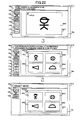
message region 100a. The user can continuously select another mode, for example, the both-side printing or the document aggregation. For example, when the user selects thedocument aggregation button 100d, processes of the document aggregation shown in Fig. 22 are started. - Fig. 22 is a diagram showing processes for designating a document aggregation. In a screen G111 shown in Fig. 22, in the
message region 100a, "SELECT NUMBER OF DOCUMENTS TO BE AGGREGATED IN ONE SHEET" is displayed, and anaggregation candidate 110 is displayed. - The
aggregation candidate 110 includes abutton 110a which aggregates two documents into one sheet, abutton 110b which aggregates four documents into one sheet, and abutton 110c which aggregates nine documents into one sheet. - For example, when a user selects the
button 110b, a screen G112 is displayed. In themessage region 100a of the screen G112, for example, a message "PUSH ENTER BUTTON WHEN ORDER IS SUITABLE, PUSH PREFERABLE ARRANGEMENT BUTTON WHEN ORDER IS TO BE CHANGED" is displayed and adocument arrangement candidate 114 is displayed instead of displaying theaggregation candidate 110. - The
document arrangement candidate 114 includesbuttons button 114a, four documents are arranged in the order of upper left, upper right, lower left, and lower right positions. In thebutton 114b, four documents are arranged in the order of upper left, lower left, upper right, and lower right positions. In thebutton 114c, four documents are arranged in the order of upper right, upper left, lower right, and lower left positions. In thebutton 114d, four documents are arranged in the order of upper right, lower right, upper left, and lower left positions. - When the screen G112 is displayed, the four documents are displayed in the arrangement order of the
button 114a. In the screen G112, the staple mark STPL31 selected by the user, the first document image IMG1, a second document image IMG2, a third document image IMG3, and a fourth document image IMG4 are displayed on the sheet image SHT1. - When the user satisfies the arrangement order shown by the
button 114a, the user pushes the enter button 110f. However, when the user does not satisfy the arrangement order shown by thebutton 114a, the user can change the arrangement order by selecting one of thebuttons 114b through 114d. - when the user pushes the enter button 110f, a screen G113 is displayed. In the
message region 110a of the screen G113, the message "SELECT MODE" is displayed. When the user pushes the both-side printing button 100c, a screen shown in Fig. 23 is displayed. - Fig. 23 is a diagram showing a screen G120 of a preview image in which both-side printing is designated. In the screen G120, in the
message region 100a, for example, a message "DRAG ON SCREEN IN PAGE TURNING DIRECTION AND CONFIRM TURNED PAGE, AND PUSH ENTER" is displayed, and a both-side preview selection 121 is displayed. - The both-
side preview selection 121 includes adevelopment view button 121a for previewing a development view, areverse button 121b for previewing a reversed preview image, and a head andtail changing button 121c for changing the head and tail. - When the user pushes the
enter button 120f, the preview image is determined for printing. - Fig. 24 is a diagram showing page turning directions. In Fig. 24(a), the page turning direction faces the STPL31. When the user drags on the screen in a direction "al" from the lower right position to the upper left position on the sheet image SHT1, the page turning status is shown in a screen G121 in Fig. 25(a). Fig. 25 is a diagram showing screens in which documents are turned.
- On the other hand, as shown in Fig. 24(b), when the user drags on the screen in a direction "a2" from the lower left position to the upper right position on the sheet image SHT1, as shown in Fig. 24(c), a
warning screen 123a is shown in the screen G120. - In Fig. 24(c), in the
warning screen 123a, a message, for example, "WARNING! DOCUMENT CANNOT BE TURNED IN DESIGNATED DIRECTION" is displayed. The user pushes anenter button 123f and designates again a page turning direction. - Referring to Fig. 25, screens in which the sheet image SHT1 is turned are described. In a screen G121 shown in Fig. 25(a), the sheet image SHT1 is started to be turned. In a screen G122 shown in Fig. 25(b), the sheet image SHT1 (first page) is turned and the rear surface of the sheet image SHT1 (second page) and a sheet image SHT2 (third page) are shown. In a screen G123 shown in Fig. 25(c), the sheet image SHT1 has been almost turned and the rear surface of the sheet image SHT1 (second page) is shown.
- Fig. 26 is a diagram showing a screen in which the sheet image SHT1 has been completely turned. As shown in Fig. 26, a screen G124 (preview screen) in which the sheet image SHT1 has been completely turned and the rear surface of the sheet image SHT1 (second page) is shown.
- Fig. 27 is a diagram showing a screen G124 in which a process returning to previous pages is shown. When the user drags on the screen G124 in a direction "a3" from the upper right position to the lower left position which direction is reverse to the page turning direction, the screen is sequentially returned from G124 to G123, G122, G122 (Fig. 25), and G120 (Fig. 24). That is, the screen is turned in reverse.
- Fig. 28 is a diagram showing a screen G125 in which the sheet image SHT2 is shown. When the user pushes the
reverse button 121b on the screen G124 shown in Fig. 27, the screen G125 shown in Fig. 28 is shown. In the screen G125, the front surface of the sheet image SHT2 (third page) is shown as a preview image. That is, in the sheet image SHT2, ninth through twelfth document images are shown. - Fig. 29 is a diagram showing processes for displaying a development view.
- In Fig. 29(a), in a screen G126, the sheet images SHT1 and SHT2 are bound by the staple mark STPL31. In the
message region 100a in the screen G126, a message, for example, "CLICK DESIRABLE PAGE, CLICKED PAGE IS DISPLAYED, PUSH ENTER". - For example, when the user clicks the - screen G126 at a point "9p" in Fig. 29(b), as shown in Fig. 29(c), in a screen G127, only the rear surface of sheet image SHT1 (second page) is enlarged and displayed.
- Fig. 30 is a diagram showing a screen G128 in which the head and tail of the rear surface of the sheet image SHT1 is changed.
- When the user pushes the head and
tail changing button 121c in the screen G127 shown in Fig. 29(c), as shown in Fig. 30, a preview image in which the head and tail of the rear surface of the sheet image SHT1 is changed is shown. - Next, referring to Figs. 31 through 38, processes for designating the page turning direction are described. A case is described. In this case, first, the user selects the both-side printing and the document aggregation, and after this, the staple position is selected.
- Fig. 31 is a diagram showing screens of a preview image in which the staple position is determined by designating the page turning direction. In Fig. 31, after the user selects the both-side printing and the document aggregation, when the user pushes the
staple button 100b, a screen G201 is displayed. In themessage region 100a of the screen G201, a message, for example, "DESIGNATE PAGE TURNING DIRECTION BY DRAG ON SCREEN" is displayed. - When the user drags in a direction "a5" (from lower to upper direction), a screen G202 is displayed. In the screen G202, the staple marks STPL21 and STPL22 are displayed along the upper side of the sheet image SHT1. In addition, in the
message region 100a of the screen G202, a message, for example, "PUSH ENTER BUTTON" is displayed. - When the user pushes an
enter button 220f, the sheet image SHT1 is determined as the preview image for printing. - Next, processes for designating the page turning direction on the sheet image SHT1 are described. Fig. 32 is a diagram showing processes for designating the page turning direction.
- In Fig. 32(a), the page turning direction is designated to be a direction facing the staple marks STPL21 and STPL22 (from lower to upper positions). That is, when the user drags on the screen G220 in a direction "a7", as shown in Fig. 32(a), the sheet image SHT1 is started to be turned. Fig. 33 is a diagram showing screens in which the sheet image SHT1 is turned.
- As shown in Fig. 32(b), when the user drags on the screen G220 in a direction "a8" (from left to right direction), a
warning screen 223a is shown in the screen G220 of Fig. 32(c). In Fig. 32(c), in thewarning screen 223a, a message, for example, "WARNING! DOCUMENT CANNOT BE TURNED IN DESIGNATED DIRECTION" is displayed. The user pushes anenter button 223f and designates again a page turning direction. - Referring to Fig. 33, turning the sheet image SHT1 is described. In Fig. 33, the turning progress is displayed as frames of moving images. In Fig. 33(a), in the screen G221, the sheet image SHT1 is started to be turned. In Fig. 33(b), in a screen G222, the rear surface of the sheet image SHT1 (second page) and the front surface of the sheet image SHT2 (third page) are started to be displayed. In Fig. 33(c), in a screen G223, the rear surface of the sheet image SHT1 (second page) has been almost displayed.
- Then, as shown in Fig. 34, when the sheet image SHT1 has been completely turned, the rear surface of the sheet image SHT1 (second page) is displayed. Fig. 34 is a diagram showing a screen G224 in which the rear surface of the sheet image SHT1 (second page) is displayed.
- Fig. 35 is a diagram showing the screen G224 in which a process returning to previous pages is shown. When the user drags on the screen G224 in a direction "a9" from the lower position to the upper position which direction is reverse to the page turning direction, the screen is sequentially returned from G224 to G223, G222, G221 (Fig. 33), and G220 (Fig. 32). That is, the screen is reversely turned.
- Fig. 36 is a diagram showing a screen G225 in which the sheet image SHT2 is shown. When the user pushes the
reverse button 121b on the screen G224 shown in Fig. 35, the screen G225 shown in Fig. 36 is displayed. In the screen G225, the front surface of the sheet image SHT2 (third page) is shown as a preview image. That is, in the sheet image SHT2, ninth through twelfth document images are shown. - When the user pushes the
development view button 121a on the screen G225, a screen flow (processes) shown in Fig. 37 is executed. Fig. 37 is a diagram showing processes to display a development view. - In Fig. 37(a), in a screen G226, the sheet images SHT1 and SHT2 are bound by the staple marks STPL21 and STPL22. In the
message region 100a in the screen G226, a message, for example, "CLICK DESIRABLE PAGE, THEN IMAGE OF CLICKED PAGE IS DISPLAYED, PUSH ENTER BUTTON". - For example, when the user clicks the screen G226 at a point "29p" in Fig. 37(b), as shown in Fig. 37(c), in a screen G227, only the rear surface of sheet image SHT1 (second page) is enlarged and displayed.
- When the user pushes the head and
tail changing button 121c on the screen G227, a preview image shown in Fig. 38(a) or 38(b) in which the head and tail of the rear surface of the sheet image SHT1 are reversed is shown in a screen G228a or G228b. - Fig. 38 is a diagram showing screens in which the head and tail of the rear surface of the sheet image SHT1 are reversed.
- In Fig. 38(a), on the screen G228a, the head and tail of each image in the SHT1 are reversed. That is, the head and tail of the images in the rear surface of the sheet image SHT1 are reversed. In Fig. 38(b), on the screen G228b, the positions of the staple marks STPL21 and STPL22 are only reversed.
- Next, processes in which a processing condition is determined before reading a document are described. Fig. 39 is a diagram showing processes (screen flow) in which a processing condition is determined before reading a document. In Fig. 39, on a screen G300, a processing condition is determined before reading a document.
- In the
message region 100a on the screen G300, a message, for example, "PUSH ENTER WHEN ORDER IS SUITABLE, PUSH PREFERABLE ARRANGEMENT BUTTON WHEN ORDER IS TO BE CHANGED" is displayed. - When the user desires to change the arrangement order of documents, the user pushes one of the buttons in the
document arrangement candidate 114. On the screen G300, the order is shown bynumbers enter button 300f, theimage processing apparatus 1 reads a first document. As shown in a screen G301, a first document image IMG1 is displayed at the position of "1" on the sheet image SHT1. - When the
image processing apparatus 1 reads a second document, as shown in a screen G302, a second document image IMG2 is displayed at the position of "2" on the sheet image SHT1. When theimage processing apparatus 1 reads a third document, as shown in a screen G303, a third document image IMG3 is displayed at the position of "3" on the sheet image SHT1. In addition, when theimage processing apparatus 1 reads a fourth document, as shown in a screen G304, a fourth document image IMG4 is displayed at the position of "4" on the sheet image SHT1. - Next, a staple position adjusting method is described. When a document image exists at a staple position, the staple position must be adjusted. Fig. 40 is a diagram showing processes (screen flow) for adjusting a staple position.
- On a screen G401 of Fig. 40, when the staple marks STPL21 and STPL22 are designated to overlap the document image IMG1 and/or the document image IMG2, a
warning screen 420 having a message, for example, "WARNING! IMAGE EXISTS AT DESIGNATED STAPLE POSITION" is displayed. Thewarning screen 420 includes a stapleposition adjusting button 420e, a document imageposition adjusting button 420f, a documentimage reducing button 420g, and anon-adjustment button 420h in which the current staple positions are used. - When the user finely adjusts the positions of the staple mark STPL21 and/or the staple mark STPL22, the user selects one of the
buttons button 420h. - Fig. 41 is a diagram showing a screen G402 in which the staple position is adjusted. When the user pushes the button 402e, the screen G402 shown in Fig. 41 is displayed. In the
message region 100a on the screen G402, a message, for example, "STAPLE POSITION IS ADJUSTED" is displayed, andstaple position adjustment 410 is displayed. - The
staple position adjustment 410 includes avertical adjustment button 410a for vertically adjusting the staple position and ahorizontal adjustment button 410b for horizontally adjusting the staple position. - The user adjusts the positions of the staple marks STPL21 and STPL22 by using the
buttons enter button 220f. - The
image processing apparatus 1 again determines whether the staple position overlaps the document image IMG1 and/or IMG2. When the staple position overlaps the document image IMG1 and/or IMG2, theimage processing apparatus 1 again displays thewarning screen 420. - In the preview
image displaying region 100e, the staple positions before adjustment are shown by broken line marks C21 and C22 on the sheet image SHT1. Therefore, the user can use thebuttons - Fig. 42 is a diagram showing a screen G403 in which the document image position is adjusted. When the user pushes the button 402f shown in Fig. 40, the screen G403 shown in Fig. 42 is displayed. In the
message region 100a on the screen G403, a message, for example, "DOCUMENT IMAGE POSITION IS ADJUSTED, INPUT FIGURE" is displayed, and documentimage position adjustment 420 is displayed. - The document
image position adjustment 420 includes avertical adjustment button 420a for vertically adjusting the document image position and ahorizontal adjustment button 420b for horizontally adjusting the document image position. - The user adjusts the positions of the document images IMG1 through IMG4 by using the
buttons enter button 220f. - The
image processing apparatus 1 again determines whether the staple position overlaps the document image IMG1 and/or IMG2. When the staple position overlaps the document image IMG1 and/or IMG2, theimage processing apparatus 1 again displays thewarning screen 420. - In the preview
image displaying region 100e, the document image positions before adjustment are shown by broken line marks D1 through D4. Therefore, the user can use thebuttons - Fig. 43 is a diagram showing a screen G404 in which the document image is reduced. When the user pushes the button 402g, the screen G404 shown in Fig. 43 is displayed. In the
message region 100a on the screen G404, a message, for example, "DOCUMENT IMAGE IS REDUCED" is displayed, andreduction adjustment 430 is displayed. - The
reduction adjustment 430 includes ascale factor button 430a. - The user reduces the sizes of the document images IMG1 through IMG4 by using the
buttons 430a. when the user determines the scale factor of the document images IMG1 through IMG4, the user pushes theenter button 220f. - The
image processing apparatus 1 again determines whether the staple position overlaps the document image IMG1 and/or IMG2. When the staple position overlaps the document image IMG1 and/or-IMG2, theimage processing apparatus 1 again displays thewarning screen 420. - In the preview
image displaying region 100e, the sizes of the document images IMG1 through IMG4 before reduction are shown by broken line marks M1 through M4. Therefore, the user can use thebutton 430a by viewing the screen G404. - As described above, in order that a staple position does not overlap a document image, the user can adjust the staple position, the document image position, or can reduce the size of the document image by viewing the preview
image displaying screen 100e. In addition, the user can combine the above adjustments (reduction). That is, a finishing process can be applied to the preview image. The finishing process includes a stapling process and a punching process. - In the staple position adjusting processes shown in Figs. 41 through 43, the adjustment (reduction) can be applied to total pages of a document, only a page designated by a user, or a two-page spread. That is, the user may select the adjustment (reduction).
- The above staple position adjustment can be applied to punch position adjustment.
- Fig. 44 is a flowchart showing processes to adjust an overlap position where a binding position of documents overlaps an image. That is, an overlap position is found where the staple position and/or the punch position overlaps an image.
- First, a user designates a binding position of documents (S31). The
image processing apparatus 1 searches for a position where the binding position overlaps an image (S32). In this case, a binding margin can be considered. - The
image processing apparatus 1 determines whether the binding position overlaps the image based on the searched result (S33). When the binding position does not overlap the image (NO in S33), the process ends. - When the binding position overlaps the image (YES in S33), the
image processing apparatus 1 displays a warning (S34). Theimage processing apparatus 1 determines whether a user adjusts the binding position (s35). When the user adjusts the binding position (YES in S35), a button for adjusting the binding position is displayed (S36). Then the process returns to S31, and the processes on and after S31 are repeated. - When the user does not adjust the binding position (NO in S35), the process ends.
- The above processes for adjusting the overlap position where the binding position of the document overlaps the image can be executed in S12 shown in Fig. 17 or in S18 shown in Fig. 17 before a preview image is displayed when the staple position and/or the punch position is designated. That is, in S12, the processing condition is designated before the
scanner 12 reads the document, and in S18, the processing condition is designated after thescanner 12 reads the document. - Next, timings of processes based on a processing condition in the
image processing apparatus 1 are described. Referring to Figs. 45 through 61, the timings of the processes are described. The processes in S13, S14, and S15 shown in Fig. 17 are realized in parallel based on a processing condition designated by the user. Each line of a document image read by thescanner 12 is stored in thePCI memory 79b, and after this, one band of the document image having predetermined number of lines is processed. The document images read by thescanner 12 are shown by the IMG1, the IMG2, the IMG3, the IMG4 ···. - Fig. 45 is a timing chart of a normal operation for displaying a preview image. Fig. 46 is a diagram showing a flow for displaying a preview image in the normal operation. Referring to Figs. 45 and 46, the normal operation for displaying a preview image based on an initial processing condition is described.
- In Fig. 45, the interrupt
processing section 79c generates an interrupt signal each time when thescanner 12 reads an image of one band having the predetermined number of lines. TheHDD 68 stores the one band image based on an image transfer clock, and the imagesynthesis processing section 41b and theexpansion memory 67a obtain the one band image based on the interrupt signal. - Each time when the one band image is stored in the
expansion memory 67a, the displaysynthesis processing section 82a synthesizes the one band images to form the document images IMG1 and IMG2. TheLCD controller 85 displays the document image IMG1 in the order of band images L1, L2, L3, L4, and L5. The band images L1 through L5 are almost simultaneously displayed. Since the displaysynthesis processing section 82a stores the document image IMG2, the document image IMG2 can be simultaneously displayed when the page is turned. As shown in Fig. 46, the document image is displayed in the order of band images L1, L2, L3, L4, and L5. - Fig. 47 is a timing chart for displaying a preview image when a rotation method is designated in a processing condition. Fig. 48 is a diagram showing the document images IMG1 when the image is read and displayed by being applied a rotation method. Referring to Figs. 47 and 48, an operation is described in which the rotation method is designated in the processing condition for displaying a preview image.
- When a user selects one of the buttons in the rotation
method selecting button 172 on the screen G100 and pushes theOK button 172f in Fig. 19, a preview image is rotated. - In Fig. 47, signals of the document images IMG1, IMG2, and IMG3 read by the
scanner 12 are instantly stored in thePCI memory 79b. In addition, theHDD 68 sequentially stores the document images IMG1, IMG2, and IMG3 based on an image transfer clock generated by thescanner 12. - When the rotation method is designated, the interrupt
processing section 79c generates an interrupt signal each time when one of the document images IMG1, IMG2, and IMG3 is stored in theHDD 68. The imagesynthesis processing section 41b instantly stores the document images IMG1, IMG2, and IMG3 by rotating the images in theexpansion memory 67a based on the interrupt signal. - Each time when the one band image is stored in the
expansion memory 67a, the displaysynthesis processing section 82a synthesizes the one band images to form the document images IMG1, IMG2, and IMG3. TheLCD controller 85 displays the document images IMG1, IMG2, and IMG3 in this order on theLCD panel 90. The document images IMG1, IMG2, and IMG3 are almost simultaneously displayed. As shown in Fig. 48, the document image IMG1 is vertically read and horizontally displayed. - Fig. 49 is a timing chart for displaying a preview image when page turning is designated by a drag of a user. Referring to Fig. 49, an operation is described in which the page turning is designated by a drag of a user on the preview
image displaying region 100e. In Fig. 49, signals of the document images IMG1, IMG2, and IMG3 read by thescanner 12 are instantly stored in thePCI memory 79b. - The interrupt
processing section 79c generates an interrupt signal each time when thescanner 12 reads an image of one band having the predetermined number of lines. TheHDD 68 stores the one band image based on an image transfer clock, and the imagesynthesis processing section 41b and theexpansion memory 67a obtain the one band image based on the interrupt signal. - Each time when the one band image is stored in the
expansion memory 67a, the displaysynthesis processing section 82a synthesizes the one band images to form the document images IMG1 and IMG2. TheLCD controller 85 displays the document image IMG1 in the order of band images L1, L2, L3, L4, and L5. The band images L1 through L5 are almost simultaneously displayed. The processes described above are almost the same as those shown in the normal operation in Fig. 45. - When the user designates to turn the document image IGM1 to a next document image (IMG2) by a drag on a screen, the
LCD controller 85 displays the document image IMG2 in the order of band images L1, L2, L3, L4, and L5. When the document image IMG2 is displayed, the displaysynthesis processing section 82a synthesizes the band images to form a next document image (the document image IMG3). - When the user designates to turn the document image IGM2, the document image IMG3 is displayed. When the user designates to turn the document image IGM3 to a previous document image, the document image IMG2 is displayed. With this, the document image of a previous page or a next page can be easily displayed.
- Fig. 50 is a timing chart for displaying a preview image when automatic page turning is designated by a user. Referring to Fig. 50, an operation is described in which the automatic page turning:is designated by pushing the automatic
page turning button 180 shown in Fig. 18 or an instruction on theimage processing apparatus 1. In Fig. 50, signals of the document images IMG1, IMG2, IMG3, and IMG4 read by thescanner 12 are instantly stored in thePCI memory 79b. - The interrupt
processing section 79c generates an interrupt signal each time when thescanner 12 reads an image of one band having the predetermined number of lines. TheHDD 68 stores the one band image based on an image transfer clock, and the imagesynthesis processing section 41b and theexpansion memory 67a obtain the one band image based on the interrupt signal. - Each time when the one band images of a document image are stored in the
expansion memory 67a, the displaysynthesis processing section 82a synthesizes the one band images to form the document image IMG1; after synthesizing the one band images of the document image IMG1, the one band images of the document image IMG2 are synthesized. The above processes are continued to synthesize the one band images to form the document image IMG4. TheLCD controller 85 displays the document image IMG1 in the order of band images L1, L2, L3, L4, and L5, after displaying the document image IMG1, the document image IMG2 is displayed. The above processes are continued to display the document image IMG4. The band images L1 through L5 are almost simultaneously displayed. - Since the document images IMG2 through IMG4 are displayed after displaying the document image IMG1 and after synthesizing the one band images thereof, the document image IMG1 is displayed longer than the document images IMG2 through IMG4. Therefore, the user can watch the document image IMG1 for a long time.
- Next, referring to Figs. 51 through 58, cases are described. In the cases, a preview image is displayed by aggregating two or more document. images into one page. For example, when four document images are aggregated into one page, the sizes of the four document images are reduced. When an enlarged document image is reduced, the image quality is degraded; therefore, it is preferable that the original document image be reduced. Therefore, as shown in the data flow of Fig. 11, the original document image stored in the
HDD 68 is used. - First, referring to Figs. 51 through 55, a first displaying method is described in which four document images are aggregated into one page. Fig. 51 is a first timing chart in which a preview image is displayed by aggregating four document images into one page. In Fig. 51, signals of the document images IMG1, IMG2, IMG3, and IMG4 read by the
scanner 12 are instantly stored in thePCI memory 79b. In addition, the signals of the document images IMG1, IMG2, IMG3, and IMG4 are sequentially stored in theHDD 68 based on an image transfer clock generated at each time when an image of one band having the predetermined number of lines is read. - The interrupt
processing section 79c calculates interrupt timing from a reducing factor designated by a processing condition. When the size of a document image is to be reduced, since the original document image is read from theHDD 68 by thinning (not reading all) data thereof, the reading speed is higher than the writing speed to theHDD 68. Therefore, the interrupt timing is determined by a predetermined algorithm with the consideration of the writing speed. For example, in a four document image aggregation, each document image, IMG1, IMG2, IMG3, or IMG4 is reduced to 1/4 size, and the reading speed is four times higher than the writing speed due to the thinning. Therefore, the interrupt timing is the time when 75% of the document image IMG1 is written in theHDD 68. - The interrupt
processing section 79c generates an interrupt signal at the calculated interrupt timing. The imagesynthesis processing section 41b sequentially reads the document images IMG1 through IMG4 based on the reading speed of the reducing factor while instantly storing the document images IMG1 through IMG4 in theexpansion memory 67a. - Each time when the one band image of the reduced document image is stored in the
expansion memory 67a, the displaysynthesis processing section 82a synthesizes the reduced document images IMG1 through IMG4 to form display images. TheLCD controller 85 sequentially displays the reduced document images IMG1 through IMG4 on theLCD panel 90 in one sheet region. The reduced document images IMG1 through IMG4 are instantly displayed. In theLCD controller 85 of Fig. 51, the displaying timings of the reduced document images IMG1 through IMG4 on one sheet in the order of upper left, upper right, lower left, and lower right positions are shown. - Referring to Figs. 52 through 55, screen flows by the displaying timings are described. Fig. 52 is a diagram showing a first screen flow in which a preview image having the four reduced document images is displayed. Fig. 53 is a diagram showing a second screen flow in which a preview image having the four reduced document images is displayed. Fig. 54 is a diagram showing a third screen flow in which a preview image having the four reduced document images is displayed. Fig. 55 is a diagram showing a fourth screen flow in which a preview image having the four reduced document images is displayed. The screen flow for displaying a preview image of four document image,aggregation is completed by connecting the screen flows shown in Figs. 52 through 55.
- In Fig. 52, first, the reduced document image IMG1 is displayed in the order of the one band images in the upper
left position 1. Next, in Fig. 53, the reduced document image IMG2 is displayed in the order of the one band images in the upperright position 2, and the reduced document image IMG3 is started to display in the order of the one band images in the lowerleft position 3. Then, in Fig. 54, the reduced document image IMG3 is displayed in the order of the one band images in the lowerleft position 3, and the reduced document image IMG4 is started to display in the order of the one band images in thelower right 4. Finally, in Fig. 55, the reduced document image IMG4 is displayed in the lowerright position 4. With this, a preview image of the four document image aggregation is completed. - Next, referring to Figs. 56 and 57, a second displaying method is described in which four document images are aggregated into one page. In the second displaying method, the band images of two reduced document images are simultaneously displayed. Fig. 56 is a second timing chart in which a preview image is displayed by aggregating four document images into one page. In Fig. 56, signals of the document images IMG1, IMG2, IMG3, and IMG4 read by the
scanner 12 are instantly stored in thePCI memory 79b. In addition, the signals of the document images IMG1, IMG2, IMG3, and IMG4 are sequentially stored in theHDD 68 based on an image transfer clock generated at each time when an image of one band having the predetermined number of lines is read. - The interrupt
processing section 79c calculates interrupt timing from a reducing factor designated by a processing condition. The calculation method of the interrupt timing is the same as that in the first displaying method described above. - The interrupt
processing section 79c generates an interrupt signal based on the calculated interrupt timing. The imagesynthesis processing section 41b sequentially reads the document images IMG1 through IMG4 based on the reading speed of the reducing factor of the four document image aggregation while instantly storing the document images IMG1 through IMG4 in theexpansion memory 67a. - Each time when the one band images of the reduced document image are stored in the
expansion memory 67a, the displaysynthesis processing section 82a sequentially synthesizes the reduced document images IMG1 through IMG4 to form display images. When the reduced document image IMG2 is formed, theLCD controller 85 simultaneously displays the reduced document images IMG1 and IMG2 on a predetermined region, and when the reduced document image IMG4 is formed, theLCD controller 85 simultaneously displays the reduced document images IMG3 and IMG4 on another predetermined region. - In the
LCD controller 85 of Fig. 56, the displaying timing to simultaneously display the reduced document images IMG1 and IMG2 on upper half position of one sheet and the displaying timing to simultaneously display the reduced document images IMG3 and IMG4 on lower half position of the one sheet are shown. - Referring to Fig. 57, a screen flow by the displaying timings is described. Fig. 57 is a diagram showing a screen flow in which a preview image having the four reduced document images is displayed based on the second timing chart. In Fig. 57, the reduced document images IMG1 and IMG2 are simultaneously displayed in the order of the one band images in the upper half positions on one sheet. Then, the reduced document images IMG3 and IMG4 are simultaneously displayed in the order of the one band images in the lower half positions on the one sheet.
- Next, referring to Fig. 58, a third displaying method is described in which two document images are aggregated into one page. In the third displaying method, the band images of two reduced document images are simultaneously displayed. Fig. 58 is a third timing chart in which a preview image is displayed by aggregating two document images into one page. In Fig. 58, signals of the document images IMG1, IMG2, IMG3, and IMG4 read by the
scanner 12 are instantly stored in thePCI memory 79b. In addition, the signals of the document images IMG1, IMG2, IMG3, and IMG4 are sequentially stored in theHDD 68 based on an image transfer clock generated at each time when an image of one band having the predetermined number of lines is read. - The interrupt
processing section 79c calculates interrupt timing from a reducing factor designated by a processing condition. The calculation method of the interrupt timing is the same as that in the first displaying method described above. However, in this case, since the reducing factor is 50%, the reading speed is twice that of the writing speed. Therefore, the interrupt timing is the time when 50% of the document image IMG1 is written in theHDD 68. - Each time when the one band images of the reduced:document image are stored in the
expansion memory 67a, the displaysynthesis processing section 82a sequentially synthesizes the reduced document images IMG1 through IMG4 to form display images. When the reduced document image IMG2 is formed, theLCD controller 85 simultaneously displays the reduced document images IMG1 and IMG2 on one sheet. - In Fig. 58, since the display
synthesis processing section 82a stores the synthesized reduced document images IMG3 and IMG4, when the page is turned, a next preview image formed of the reduced document images IMG3 and IMG4 can be quickly displayed. - Referring to Figs. 59 through 61, a case is described. In this case, a preview image of a document image is displayed by attaching a staple mark to the preview image. When the user pushes the
staple button 100b on the screen G100 displaying a preview image shown in Fig. 18, theimage processing apparatus 1 synthesizes a staple mark on a band image where the staple mark is to be displayed and displays a preview image having the staple mark. - In Figs. 59 through 61, one staple mark is attached to the document image IMG1. However, when plural staple marks are attached to the document image IMG1, the same processes as those shown in Fig. 59 can be used. Fig. 59 is a timing chart showing processes to attach a staple mark on a preview image of a document image. In Fig. 59, signals of the document image IMG1 read by the
scanner 12 are instantly stored in thePCI memory 79b. - The interrupt
processing section 79c generates an interrupt signal each time when thescanner 12 reads an image of one band having the predetermined number of lines. TheHDD 68 stores the one band image based on an image transfer clock, and the imagesynthesis processing section 41b and theexpansion memory 67a obtain the one band image based on the interrupt signal. - Each time when the one band images are stored in the
expansion memory 67a, the displaysynthesis processing section 82a synthesizes the one band images to form the document image IMG1. TheLCD controller 85 displays the document image IMG1 in the order of band images L1, L2, L3, L4, and L5. The band images L1 through L5 are almost simultaneously displayed. - When the user pushes the
staple button 100b and designates the position of a staple mark in the document image IMG1 which is previewed, the displaysynthesis processing section 82a synthesizes a part of the band image L1 where the staple is to be attached with a staple mark read from thesymbol mark region 84a (partial synthesis 51) and rewrites the position of the staple mark on a part of the band image where the staple mark is already positioned. Then the new staple mark position is displayed. In Fig. 59, theLCD controller 85 displays the staple mark position at a position L1'. - When the document images IMG2, IMG3, IMG4, ··· are read after reading the document image IMG1, the normal operation shown in Fig. 45 is used.
- Fig. 60 is a screen flow when a staple mark is attached to a preview image. In Fig. 60, when a document image is displayed by the band images L1 through L5 and the user designates a staple position of a staple mark M31, the band image L1 is replaced by a
synthesis image part 52. - When a preview image is displayed by being enlarged, as shown in Fig. 61, a part of the document image is replaced by a new image. Fig. 61 is a diagram showing screens of preview images in which the staple position is determined. In a screen G501 shown of Fig. 61(a), on a sheet image SHT1 of a normal preview display, a staple position is determined and the staple mark L31 is displayed. In a screen G502 of Fig. 61(b), the staple position is enlarged.
- As described above, according to the embodiment of the present invention, a user can determine a processing condition for printing a document image by directly operating a preview image. In addition, the user can determine the processing condition by operations such as a click and a drag. Further, the user can visually and intuitively determine the processing condition.
- Moreover, according to the embodiment of the present invention, when the user touches a desirable position on a preview image, the user can designate a binding position by a staple. In addition, since the user can operate on the preview image by touching a screen and pushing a button, the operability for the user can be increased.
- Further, the present invention is not limited to the specifically disclosed embodiment, and variations and modifications may be made without departing from the scope of the present invention.
- The present invention is based on
Japanese Priority Patent Application No. 2006-073406, filed on March 16, 2006 Japanese Priority Patent Application No. 2007-060381, filed on March 9, 2007
Claims (16)
- An image processing apparatus which previews a read image, the image processing apparatus characterized by:a preview image processing unit in which a user is allowed to set a processing condition for the read preview image by operating on the read preview image and a preview image processed by the processing condition is displayed together with the setting of the processing condition on a displaying section.
- The image processing apparatus as claimed in claim 1, characterized in that the preview image processing unit allows the user to apply a process to the read preview image to which the processing condition is to be applied and displays a processed preview image on a displaying section.
- The image processing apparatus as claimed:in claim 2, characterized in that the preview image processing unit makes the user designate a finishing process for the read preview image as the processing condition.
- The image processing apparatus as claimed in claim 1 or 2, characterized in that image processing timing is changed corresponding to the set processing condition.
- The image processing apparatus as claimed in claim 4, characterized in that at least one of image synthesizing timing to form a print image and image synthesizing timing to form a preview image is changed for the read image by a scanner corresponding to the setting of the processing condition.
- The image processing apparatus as claimealin any one of claims 2 through 5, characterized in that the preview image processing unit allows the user to designate a binding position of the read preview images by dragging on the read preview image in a page turning direction, and displays the page turning status in a moving image.
- The image processing apparatus as claimed in claim 6, characterized in that the preview image processing unit displays a message when the page turning direction dragged by the user on the read preview image does not correspond to the binding position of the documents.
- The image processing apparatus as claimed in claim 6 or 7, characterized in that the preview image processing unit includes
a determining unit for determining whether the binding position of the documents overlaps the read preview image; and
a warning message displaying unit for displaying a warning message when the binding position of the documents overlaps the read preview image. - The image processing apparatus as claimed in claim 8, characterized in that the preview image processing unit displays a function button for adjusting the binding position of the documents when the binding position of the documents overlaps the read preview image.
- The image processing apparatus as claimed in any one of claims 1 through 9, characterized in that the preview image processing unit is effective before and after reading an image.
- A preview image displaying method which previews a read image on a displaying panel in an image processing apparatus, the preview image displaying method characterized by;a preview image processing step in which a user is allowed to set a processing condition for the read preview image by operating on the read preview image and a preview image processed by the processing condition is displayed together with the setting of the processing condition on the displaying panel.
- The preview image displaying method as claimed in claim 11, characterized in that the preview image processing step allows the user to designate a binding position of documents on the read preview image.
- The preview image displaying method as claimed in claim 11, characterized in that the preview image processing step makes the user designate a finishing process for the read preview image as the processing condition.
- The preview image displaying method as claimed in any one of claims 11 through 13, characterized in that image processing timing is changed corresponding to the set processing condition.
- The preview image displaying method as claimed in any one of claims 11 through 14, characterized in that the preview image processing step is effective before and after reading an image.
- A computer program comprising program code means that, when executed by a computer system or image processing apparatus, instructs the computer system for image processing apparatus to effect a method according to any one of claims 11 to 15
Applications Claiming Priority (2)
| Application Number | Priority Date | Filing Date | Title |
|---|---|---|---|
| JP2006073406 | 2006-03-16 | ||
| JP2007060381A JP5030622B2 (en) | 2006-03-16 | 2007-03-09 | Image processing apparatus and preview display method |
Publications (3)
| Publication Number | Publication Date |
|---|---|
| EP1835715A2 true EP1835715A2 (en) | 2007-09-19 |
| EP1835715A3 EP1835715A3 (en) | 2008-12-24 |
| EP1835715B1 EP1835715B1 (en) | 2015-05-06 |
Family
ID=38291309
Family Applications (1)
| Application Number | Title | Priority Date | Filing Date |
|---|---|---|---|
| EP20070251076 Not-in-force EP1835715B1 (en) | 2006-03-16 | 2007-03-14 | Image processing apparatus and method with preview display of images subjected to selected processing options |
Country Status (3)
| Country | Link |
|---|---|
| US (1) | US7643187B2 (en) |
| EP (1) | EP1835715B1 (en) |
| JP (1) | JP5030622B2 (en) |
Cited By (4)
| Publication number | Priority date | Publication date | Assignee | Title |
|---|---|---|---|---|
| EP2068545A1 (en) | 2007-12-03 | 2009-06-10 | Océ-Technologies B.V. | Document scanning system |
| CN102520855A (en) * | 2011-12-03 | 2012-06-27 | 鸿富锦精密工业(深圳)有限公司 | Electronic equipment with touch screen and page turning method for electronic equipment |
| NL2021943B1 (en) * | 2018-11-06 | 2020-05-15 | Canon Production Printing Holding Bv | A Method of Creating a Print Job for a Multi-Page Print Product |
| US20220137899A1 (en) * | 2020-11-04 | 2022-05-05 | Seiko Epson Corporation | Non-transitory computer-readable storage medium storing program, display method, and print controller |
Families Citing this family (43)
| Publication number | Priority date | Publication date | Assignee | Title |
|---|---|---|---|---|
| US7539433B2 (en) * | 2006-03-09 | 2009-05-26 | Kabushiki Kaisha Toshiba | Image forming apparatus |
| US8098395B2 (en) * | 2007-03-30 | 2012-01-17 | Ricoh Company, Ltd | System and method for image thumbnail/preview on an image processing device |
| JP2008209985A (en) * | 2007-02-23 | 2008-09-11 | Canon Inc | Data processing apparatus, electronic document registration method, and computer program |
| JP4849001B2 (en) * | 2007-04-19 | 2011-12-28 | コニカミノルタビジネステクノロジーズ株式会社 | Image processing apparatus, image forming apparatus, and program |
| JP2009017019A (en) * | 2007-07-02 | 2009-01-22 | Sharp Corp | Image forming apparatus, image forming method, image forming program, and recording medium |
| JP4782735B2 (en) * | 2007-07-04 | 2011-09-28 | シャープ株式会社 | Image processing device |
| US20090103114A1 (en) * | 2007-10-22 | 2009-04-23 | Ricoh Company, Ltd. | Multifunction printer and method for confirming preview image |
| JP5314887B2 (en) | 2007-12-20 | 2013-10-16 | インターナショナル・ビジネス・マシーンズ・コーポレーション | Setting method of output image including image processing information and setting control program thereof |
| JP5438916B2 (en) * | 2008-05-16 | 2014-03-12 | 京セラドキュメントソリューションズ株式会社 | Image forming apparatus |
| JP4572248B2 (en) * | 2008-06-23 | 2010-11-04 | シャープ株式会社 | Image processing apparatus, image forming apparatus, image processing method, control program, and recording medium |
| JP4787865B2 (en) * | 2008-07-25 | 2011-10-05 | シャープ株式会社 | Image forming apparatus |
| CN101762998B (en) * | 2008-12-24 | 2012-10-31 | 京瓷办公信息系统株式会社 | Image forming device and preview display method |
| JP4766136B2 (en) * | 2009-03-19 | 2011-09-07 | コニカミノルタビジネステクノロジーズ株式会社 | Image processing apparatus, image processing method, and program |
| JP4943527B2 (en) * | 2010-03-25 | 2012-05-30 | シャープ株式会社 | Image display operation device and image forming apparatus having the same |
| JP5112471B2 (en) * | 2010-05-11 | 2013-01-09 | シャープ株式会社 | Image display operation device and image forming apparatus having the same |
| JP5031069B2 (en) * | 2010-06-07 | 2012-09-19 | シャープ株式会社 | Image processing apparatus, image forming system, computer program, and image display method |
| JP2012015846A (en) * | 2010-07-01 | 2012-01-19 | Canon Inc | Image processing apparatus, display control method, and program |
| JP5200065B2 (en) * | 2010-07-02 | 2013-05-15 | 富士フイルム株式会社 | Content distribution system, method and program |
| JP5646898B2 (en) * | 2010-07-22 | 2014-12-24 | シャープ株式会社 | Image forming apparatus |
| JP5601070B2 (en) * | 2010-07-27 | 2014-10-08 | コニカミノルタ株式会社 | GUI mounting program, GUI mounting apparatus, and GUI mounting method |
| JP5192019B2 (en) * | 2010-09-22 | 2013-05-08 | シャープ株式会社 | Image forming apparatus |
| JP5161280B2 (en) * | 2010-09-27 | 2013-03-13 | シャープ株式会社 | Image display operation device and image forming apparatus having the same |
| JP5533790B2 (en) * | 2011-06-15 | 2014-06-25 | コニカミノルタ株式会社 | Client server system provided with web application, and client device in the client server system |
| JP5541240B2 (en) | 2011-07-12 | 2014-07-09 | コニカミノルタ株式会社 | Image forming apparatus and image processing method |
| JP2013056472A (en) * | 2011-09-08 | 2013-03-28 | Canon Inc | Image forming apparatus and method for controlling the same, and program and recording medium |
| JP6107225B2 (en) * | 2012-03-12 | 2017-04-05 | コニカミノルタ株式会社 | Image processing apparatus, control method for image processing apparatus, and control program |
| JP5668725B2 (en) | 2012-06-18 | 2015-02-12 | コニカミノルタ株式会社 | Image processing apparatus, display apparatus, and program |
| JP5598500B2 (en) | 2012-06-18 | 2014-10-01 | コニカミノルタ株式会社 | Image processing apparatus, display apparatus, and program |
| JP5772751B2 (en) | 2012-07-30 | 2015-09-02 | コニカミノルタ株式会社 | Image processing apparatus, display apparatus, and program |
| JP2014071568A (en) * | 2012-09-28 | 2014-04-21 | Brother Ind Ltd | Image processing program and image processing device |
| JP2014086836A (en) * | 2012-10-23 | 2014-05-12 | Canon Inc | Image processing apparatus, control method, and program |
| CN102970343B (en) * | 2012-10-31 | 2015-04-08 | 小米科技有限责任公司 | Method and device for displaying push information |
| JP6071487B2 (en) * | 2012-11-30 | 2017-02-01 | キヤノン株式会社 | Print control apparatus, print control method, and program |
| JP2015111819A (en) * | 2013-10-30 | 2015-06-18 | ブラザー工業株式会社 | Reading device and image processing system |
| JP2015100951A (en) * | 2013-11-22 | 2015-06-04 | キヤノン株式会社 | Image forming apparatus, image forming apparatus control method, and program |
| US10136025B2 (en) * | 2015-09-16 | 2018-11-20 | Canon Kabushiki Kaisha | Image processing apparatus capable of generating image, method of controlling the same, and storage medium |
| USD835117S1 (en) * | 2016-02-18 | 2018-12-04 | Branch Banking And Trust Company | Display screen or portion thereof with graphical user interface |
| JP2017185673A (en) * | 2016-04-05 | 2017-10-12 | セイコーエプソン株式会社 | Printer |
| USD825580S1 (en) * | 2016-05-27 | 2018-08-14 | Adp, Llc | Display screen or portion thereof with graphical user interface |
| JP6708501B2 (en) * | 2016-07-08 | 2020-06-10 | キヤノン株式会社 | Printing device, printing device control method, and program |
| JP7129249B2 (en) * | 2018-07-06 | 2022-09-01 | キヤノン株式会社 | Program, information processing device, and control method thereof |
| JP7731630B2 (en) | 2021-07-07 | 2025-09-01 | キヤノン株式会社 | Image processing device, image processing method, and program |
| JP7852263B2 (en) * | 2022-01-31 | 2026-04-28 | ブラザー工業株式会社 | printing device |
Citations (3)
| Publication number | Priority date | Publication date | Assignee | Title |
|---|---|---|---|---|
| US6115510A (en) | 1995-07-20 | 2000-09-05 | Canon Kabushiki Kaisha | Image processing apparatus capable of displaying image to be formed on sheet |
| JP2006073406A (en) | 2004-09-03 | 2006-03-16 | Sanyo Electric Co Ltd | Charging method |
| JP2007060381A (en) | 2005-08-25 | 2007-03-08 | Oki Electric Ind Co Ltd | Ip telephone system for providing voice guidance |
Family Cites Families (17)
| Publication number | Priority date | Publication date | Assignee | Title |
|---|---|---|---|---|
| US4871158A (en) * | 1989-02-27 | 1989-10-03 | Xerox Corporation | Very high speed duplicator with finishing function |
| JP3974948B2 (en) * | 1994-10-07 | 2007-09-12 | 株式会社日立製作所 | Page turning display method and apparatus |
| US6473539B1 (en) * | 1996-12-02 | 2002-10-29 | Canon Kabushiki Kaisha | Image processing apparatus with an image and binding positions display feature, related method, and medium |
| JP2001067347A (en) * | 1999-06-23 | 2001-03-16 | Canon Inc | Information processing device, information processing method, and storage medium storing computer readable program |
| JP2001045239A (en) | 1999-08-02 | 2001-02-16 | Canon Inc | Scanner device, control method thereof, and memory medium |
| JP2001265481A (en) * | 2000-03-21 | 2001-09-28 | Nec Corp | Method and device for displaying page information and storage medium with program for displaying page information stored |
| GB0009129D0 (en) * | 2000-04-14 | 2000-05-31 | Picsel Technologies Limited | Digital document processing |
| JP2003060823A (en) * | 2001-06-06 | 2003-02-28 | Canon Inc | Image forming apparatus, image forming method, medium for providing control program, and control program |
| US7911638B2 (en) * | 2002-12-27 | 2011-03-22 | Canon Kabushiki Kaisha | Image processing apparatus, image processing method, and image processing program |
| JP2004234261A (en) | 2003-01-29 | 2004-08-19 | Ricoh Co Ltd | Image reading device |
| JP2004282439A (en) * | 2003-03-17 | 2004-10-07 | Kyocera Mita Corp | Image forming apparatus |
| JP2005115683A (en) * | 2003-10-08 | 2005-04-28 | Canon Inc | Print setting method and information processing apparatus |
| JP4401850B2 (en) * | 2004-04-16 | 2010-01-20 | キヤノン株式会社 | Document processing apparatus and method |
| JP3894203B2 (en) * | 2004-05-27 | 2007-03-14 | コニカミノルタビジネステクノロジーズ株式会社 | Display device, display system, display method, and display program |
| JP2006041947A (en) * | 2004-07-27 | 2006-02-09 | Ricoh Co Ltd | Image forming apparatus, image forming method, and program causing computer to execute the method |
| US9104358B2 (en) * | 2004-12-01 | 2015-08-11 | Xerox Corporation | System and method for document production visualization |
| US7975224B2 (en) * | 2005-12-21 | 2011-07-05 | Xerox Corporation | WYSIWYG multifunction device finishing options |
-
2007
- 2007-03-09 JP JP2007060381A patent/JP5030622B2/en active Active
- 2007-03-14 EP EP20070251076 patent/EP1835715B1/en not_active Not-in-force
- 2007-03-15 US US11/686,662 patent/US7643187B2/en active Active
Patent Citations (3)
| Publication number | Priority date | Publication date | Assignee | Title |
|---|---|---|---|---|
| US6115510A (en) | 1995-07-20 | 2000-09-05 | Canon Kabushiki Kaisha | Image processing apparatus capable of displaying image to be formed on sheet |
| JP2006073406A (en) | 2004-09-03 | 2006-03-16 | Sanyo Electric Co Ltd | Charging method |
| JP2007060381A (en) | 2005-08-25 | 2007-03-08 | Oki Electric Ind Co Ltd | Ip telephone system for providing voice guidance |
Cited By (4)
| Publication number | Priority date | Publication date | Assignee | Title |
|---|---|---|---|---|
| EP2068545A1 (en) | 2007-12-03 | 2009-06-10 | Océ-Technologies B.V. | Document scanning system |
| CN102520855A (en) * | 2011-12-03 | 2012-06-27 | 鸿富锦精密工业(深圳)有限公司 | Electronic equipment with touch screen and page turning method for electronic equipment |
| NL2021943B1 (en) * | 2018-11-06 | 2020-05-15 | Canon Production Printing Holding Bv | A Method of Creating a Print Job for a Multi-Page Print Product |
| US20220137899A1 (en) * | 2020-11-04 | 2022-05-05 | Seiko Epson Corporation | Non-transitory computer-readable storage medium storing program, display method, and print controller |
Also Published As
| Publication number | Publication date |
|---|---|
| US20070216973A1 (en) | 2007-09-20 |
| EP1835715A3 (en) | 2008-12-24 |
| US7643187B2 (en) | 2010-01-05 |
| JP2007280369A (en) | 2007-10-25 |
| JP5030622B2 (en) | 2012-09-19 |
| EP1835715B1 (en) | 2015-05-06 |
Similar Documents
| Publication | Publication Date | Title |
|---|---|---|
| EP1835715B1 (en) | Image processing apparatus and method with preview display of images subjected to selected processing options | |
| CN100562057C (en) | Image processing apparatus and preview image displaying method | |
| JP4787779B2 (en) | Image processing apparatus, program, and preview image display method | |
| US8174709B2 (en) | Image processing apparatus, computer program product, and preview image displaying method | |
| US9118788B2 (en) | Display device and method of controlling the same | |
| JP4922021B2 (en) | Image processing apparatus, program, and preview image display method | |
| US6978095B2 (en) | Multi-function processing apparatus and control program for changing display according to frequency | |
| JP4375578B2 (en) | Image forming apparatus and setting method in image forming apparatus | |
| JP4828338B2 (en) | Image processing apparatus and program | |
| JP2008203439A (en) | Image processing apparatus, preview image display method, and preview image display program | |
| JP2007160922A (en) | Image processor, program, and finish data movement method in image processor | |
| JP7027248B2 (en) | Image processing equipment, programs, image processing methods | |
| JP2011216096A (en) | Device, program, storage medium, and image display method | |
| JP2008229851A (en) | Image processing apparatus, program, and preview image display method | |
| JP2013252622A (en) | Image forming device, method, and program | |
| JP2017063467A (en) | Image processing apparatus | |
| JP4731916B2 (en) | Image display device and display control program | |
| JP3956788B2 (en) | Copy machine | |
| JP3987066B2 (en) | Image forming apparatus, image forming method, and program | |
| JP2008124895A (en) | Image reading apparatus and image forming apparatus | |
| JP2024125724A (en) | Image processing device, control method, and program | |
| KR100571918B1 (en) | Method and apparatus for automatically duplex printing on area smaller than the size of paper to be printed | |
| JP2026081948A (en) | Programs, image processing methods, information processing devices, printing systems | |
| JPH10150560A (en) | Image processing device | |
| JP2019205169A (en) | Image display operation device, image forming apparatus, and image display operation method |
Legal Events
| Date | Code | Title | Description |
|---|---|---|---|
| PUAI | Public reference made under article 153(3) epc to a published international application that has entered the european phase |
Free format text: ORIGINAL CODE: 0009012 |
|
| 17P | Request for examination filed |
Effective date: 20070405 |
|
| AK | Designated contracting states |
Kind code of ref document: A2 Designated state(s): AT BE BG CH CY CZ DE DK EE ES FI FR GB GR HU IE IS IT LI LT LU LV MC MT NL PL PT RO SE SI SK TR |
|
| AX | Request for extension of the european patent |
Extension state: AL BA HR MK YU |
|
| PUAL | Search report despatched |
Free format text: ORIGINAL CODE: 0009013 |
|
| AK | Designated contracting states |
Kind code of ref document: A3 Designated state(s): AT BE BG CH CY CZ DE DK EE ES FI FR GB GR HU IE IS IT LI LT LU LV MC MT NL PL PT RO SE SI SK TR |
|
| AX | Request for extension of the european patent |
Extension state: AL BA HR MK RS |
|
| RIC1 | Information provided on ipc code assigned before grant |
Ipc: G03G 15/00 20060101ALI20081118BHEP Ipc: H04N 1/00 20060101AFI20070802BHEP Ipc: H04N 1/387 20060101ALI20081118BHEP |
|
| 17Q | First examination report despatched |
Effective date: 20090618 |
|
| AKX | Designation fees paid |
Designated state(s): DE ES FR GB IT NL |
|
| GRAP | Despatch of communication of intention to grant a patent |
Free format text: ORIGINAL CODE: EPIDOSNIGR1 |
|
| INTG | Intention to grant announced |
Effective date: 20141124 |
|
| GRAS | Grant fee paid |
Free format text: ORIGINAL CODE: EPIDOSNIGR3 |
|
| GRAA | (expected) grant |
Free format text: ORIGINAL CODE: 0009210 |
|
| AK | Designated contracting states |
Kind code of ref document: B1 Designated state(s): DE ES FR GB IT NL |
|
| REG | Reference to a national code |
Ref country code: GB Ref legal event code: FG4D |
|
| REG | Reference to a national code |
Ref country code: DE Ref legal event code: R096 Ref document number: 602007041326 Country of ref document: DE Effective date: 20150611 |
|
| REG | Reference to a national code |
Ref country code: NL Ref legal event code: MP Effective date: 20150506 |
|
| PG25 | Lapsed in a contracting state [announced via postgrant information from national office to epo] |
Ref country code: ES Free format text: LAPSE BECAUSE OF FAILURE TO SUBMIT A TRANSLATION OF THE DESCRIPTION OR TO PAY THE FEE WITHIN THE PRESCRIBED TIME-LIMIT Effective date: 20150506 |
|
| REG | Reference to a national code |
Ref country code: DE Ref legal event code: R097 Ref document number: 602007041326 Country of ref document: DE |
|
| PLBE | No opposition filed within time limit |
Free format text: ORIGINAL CODE: 0009261 |
|
| STAA | Information on the status of an ep patent application or granted ep patent |
Free format text: STATUS: NO OPPOSITION FILED WITHIN TIME LIMIT |
|
| REG | Reference to a national code |
Ref country code: FR Ref legal event code: PLFP Year of fee payment: 10 |
|
| 26N | No opposition filed |
Effective date: 20160209 |
|
| PG25 | Lapsed in a contracting state [announced via postgrant information from national office to epo] |
Ref country code: IT Free format text: LAPSE BECAUSE OF FAILURE TO SUBMIT A TRANSLATION OF THE DESCRIPTION OR TO PAY THE FEE WITHIN THE PRESCRIBED TIME-LIMIT Effective date: 20150506 |
|
| REG | Reference to a national code |
Ref country code: FR Ref legal event code: PLFP Year of fee payment: 11 |
|
| PG25 | Lapsed in a contracting state [announced via postgrant information from national office to epo] |
Ref country code: NL Free format text: LAPSE BECAUSE OF FAILURE TO SUBMIT A TRANSLATION OF THE DESCRIPTION OR TO PAY THE FEE WITHIN THE PRESCRIBED TIME-LIMIT Effective date: 20150506 |
|
| REG | Reference to a national code |
Ref country code: FR Ref legal event code: PLFP Year of fee payment: 12 |
|
| PGFP | Annual fee paid to national office [announced via postgrant information from national office to epo] |
Ref country code: FR Payment date: 20210323 Year of fee payment: 15 |
|
| PGFP | Annual fee paid to national office [announced via postgrant information from national office to epo] |
Ref country code: DE Payment date: 20210319 Year of fee payment: 15 Ref country code: GB Payment date: 20210325 Year of fee payment: 15 |
|
| REG | Reference to a national code |
Ref country code: DE Ref legal event code: R119 Ref document number: 602007041326 Country of ref document: DE |
|
| GBPC | Gb: european patent ceased through non-payment of renewal fee |
Effective date: 20220314 |
|
| PG25 | Lapsed in a contracting state [announced via postgrant information from national office to epo] |
Ref country code: GB Free format text: LAPSE BECAUSE OF NON-PAYMENT OF DUE FEES Effective date: 20220314 Ref country code: FR Free format text: LAPSE BECAUSE OF NON-PAYMENT OF DUE FEES Effective date: 20220331 Ref country code: DE Free format text: LAPSE BECAUSE OF NON-PAYMENT OF DUE FEES Effective date: 20221001 |