EP1835599B1 - Method for manufacturing a stator core of an axial air-gap motor - Google Patents
Method for manufacturing a stator core of an axial air-gap motor Download PDFInfo
- Publication number
- EP1835599B1 EP1835599B1 EP07251072.0A EP07251072A EP1835599B1 EP 1835599 B1 EP1835599 B1 EP 1835599B1 EP 07251072 A EP07251072 A EP 07251072A EP 1835599 B1 EP1835599 B1 EP 1835599B1
- Authority
- EP
- European Patent Office
- Prior art keywords
- punch
- core
- stator
- punches
- sheet
- Prior art date
- Legal status (The legal status is an assumption and is not a legal conclusion. Google has not performed a legal analysis and makes no representation as to the accuracy of the status listed.)
- Active
Links
Images


Classifications
-
- H—ELECTRICITY
- H02—GENERATION; CONVERSION OR DISTRIBUTION OF ELECTRIC POWER
- H02K—DYNAMO-ELECTRIC MACHINES
- H02K15/00—Methods or apparatus specially adapted for manufacturing, assembling, maintaining or repairing of dynamo-electric machines
- H02K15/02—Methods or apparatus specially adapted for manufacturing, assembling, maintaining or repairing of dynamo-electric machines of stator or rotor bodies
- H02K15/022—Methods or apparatus specially adapted for manufacturing, assembling, maintaining or repairing of dynamo-electric machines of stator or rotor bodies with salient poles or claw-shaped poles
-
- H—ELECTRICITY
- H02—GENERATION; CONVERSION OR DISTRIBUTION OF ELECTRIC POWER
- H02K—DYNAMO-ELECTRIC MACHINES
- H02K1/00—Details of the magnetic circuit
- H02K1/06—Details of the magnetic circuit characterised by the shape, form or construction
- H02K1/12—Stationary parts of the magnetic circuit
- H02K1/18—Means for mounting or fastening magnetic stationary parts on to, or to, the stator structures
-
- H—ELECTRICITY
- H02—GENERATION; CONVERSION OR DISTRIBUTION OF ELECTRIC POWER
- H02K—DYNAMO-ELECTRIC MACHINES
- H02K21/00—Synchronous motors having permanent magnets; Synchronous generators having permanent magnets
- H02K21/12—Synchronous motors having permanent magnets; Synchronous generators having permanent magnets with stationary armatures and rotating magnets
- H02K21/24—Synchronous motors having permanent magnets; Synchronous generators having permanent magnets with stationary armatures and rotating magnets with magnets axially facing the armatures, e.g. hub-type cycle dynamos
-
- H—ELECTRICITY
- H02—GENERATION; CONVERSION OR DISTRIBUTION OF ELECTRIC POWER
- H02K—DYNAMO-ELECTRIC MACHINES
- H02K2201/00—Specific aspects not provided for in the other groups of this subclass relating to the magnetic circuits
- H02K2201/15—Sectional machines
-
- Y—GENERAL TAGGING OF NEW TECHNOLOGICAL DEVELOPMENTS; GENERAL TAGGING OF CROSS-SECTIONAL TECHNOLOGIES SPANNING OVER SEVERAL SECTIONS OF THE IPC; TECHNICAL SUBJECTS COVERED BY FORMER USPC CROSS-REFERENCE ART COLLECTIONS [XRACs] AND DIGESTS
- Y10—TECHNICAL SUBJECTS COVERED BY FORMER USPC
- Y10T—TECHNICAL SUBJECTS COVERED BY FORMER US CLASSIFICATION
- Y10T29/00—Metal working
- Y10T29/49—Method of mechanical manufacture
- Y10T29/49002—Electrical device making
- Y10T29/49009—Dynamoelectric machine
- Y10T29/49012—Rotor
-
- Y—GENERAL TAGGING OF NEW TECHNOLOGICAL DEVELOPMENTS; GENERAL TAGGING OF CROSS-SECTIONAL TECHNOLOGIES SPANNING OVER SEVERAL SECTIONS OF THE IPC; TECHNICAL SUBJECTS COVERED BY FORMER USPC CROSS-REFERENCE ART COLLECTIONS [XRACs] AND DIGESTS
- Y10—TECHNICAL SUBJECTS COVERED BY FORMER USPC
- Y10T—TECHNICAL SUBJECTS COVERED BY FORMER US CLASSIFICATION
- Y10T29/00—Metal working
- Y10T29/49—Method of mechanical manufacture
- Y10T29/49995—Shaping one-piece blank by removing material
Definitions
- the present invention relates to a method for manufacturing a stator core for an axial air-gap electronic motor in which a rotor and a stator are arranged opposedly along the axis direction of a rotor output shaft. More particularly, it relates to a method for manufacturing a stator core for an axial air-gap electronic motor, in which core sheets are laminated into a trapezoidal shape along the radial direction.
- an axial air-gap electronic motor is formed so that a rotor is arranged along the axis direction of a rotor output shaft opposedly on both sides (or on one side) of a disc-shaped stator with a predetermined gap being provided therebetween.
- the axial air-gap electronic motor has an advantage of being capable of being made small in size because the axial length thereof can be shortened.
- the stator has a plurality of stator cores (core members), and the stator cores are arranged in an annular shape around a bearing portion provided in the center, and are molded integrally by synthetic resin.
- the stator core for the axial air-gap electronic motor is formed by laminating a plurality of core sheets along the radial direction.
- the stator core is contrived to increase the teeth area by being formed into a trapezoidal shape such that the width in the circumferential direction increases gradually from the center side to the outside.
- stator cores also has been proposed in which the side surface in the circumferential direction (slot surface) is provided with a skew to restrain the occurrence of cogging torque.
- U.S. Patent No. 5,640,752 describes an adjustable method for forming and stacking laminations that are used in an electromagnetic device using two separate punches.
- JP 2006 014565 A describes a stator core having trapezoidal shaped core elements.
- JP 2004 007936 A describes a process for manufacturing a motor core by punching a metal plate.
- stator core for the axial air-gap electronic motor has problems described below.
- stator cores are laminated along the radial direction. Therefore, since the teeth surface must be formed into a trapezoidal shape, the shape of core sheet must be changed one by one. Also, since the shape must be changed every one sheet, blanking dies corresponding to the number of core sheets are needed, which increases the production cost.
- the core sheets in order for the slot surface to take a slantwise shape, the core sheets must be laminated while shifting slightly one by one, which takes much time and labor. Further, since the core sheets are laminated in a shifted state, the positioning requires a technique.
- the present invention has been made to solve the above problems, and accordingly an object thereof is to provide a method for manufacturing a stator core for an axial air-gap electronic motor, in which core sheets are laminatedly fixed while being shifted with predetermined intervals.
- the present invention provides a method for manufacturing a stator core for an axial air-gap electronic motor in which a stator and a rotor are arranged opposedly along the axis line direction of a rotor output shaft, the stator core, consisting of a laminated body formed by laminating a plurality of core sheets blanked from a metallic mother sheet in the radial direction, being formed into a trapezoidal shape the circumferential width of which increases gradually from the center of the rotor output shaft toward the outside, wherein a first cutting portion for forming a first side surface (first slot surface) in the circumferential direction of the core sheet, a second cutting portion for forming a second side surface (second slot surface) in the circumferential direction of the core sheet, a first moving means for reciprocatingly moving the first cutting portion, and a second moving means for reciprocatingly moving the second cutting portion are provided, and the method includes a first blanking step in which the first slot surfaces
- the width between the side surfaces (the first slot surface and the second slot surface) in the circumferential direction of the stator core can be changed by the two cutting portions moving independently, by which the stator core can be laminated without the use of a plurality of dies.
- the first cutting portion and the second cutting portion are arranged opposedly so as to be brought close to each other or separated from each other.
- the first cutting portion and the second cutting portion move asynchronously.
- the first cutting portion is provided in a pair at the right and left with a predetermined clearance being provided therebetween, and the second cutting portion is arranged therebetween, whereby the first and second slot surfaces of two of the core sheets are blanked out of the mother sheet.
- the stator core is assembled in point symmetry by laminating the core sheets blanked out of the mother sheet along the radial direction.
- the second cutting portion is arranged between the paired right and left first cutting portions and these cutting portions are driven asynchronously, so that two core sheets can be manufactured at the same time. Also, by blanking the core sheets in a point symmetry shape, two second slot surfaces can be blanked at the same time by one second cutting portion. Therefore, the yield increases, and hence the productivity can further be improved.
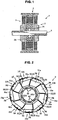
- FIG. 1 is a schematic sectional view of an axial air-gap electronic motor having a stator core, which is manufactured by a manufacturing method in accordance with one embodiment of the present invention
- FIG. 2 is a front view of a stator of the axial air-gap electronic motor shown in FIG. 1 .
- the axial air-gap electronic motor 1 includes a stator 2 formed into a disc shape and a pair of rotors 3 arranged opposedly on both side surfaces of the stator 2 with a predetermined gap being provided therebetween.
- Each of the rotors 3 is coaxially fixed to a rotor output shaft 4 that produces a rotational driving force.
- the stator 2 and the rotors 3 are housed in a bracket, not shown.
- the outer peripheral surface of the stator 2 is also used as the outer peripheral wall of the bracket, and at both ends thereof, a lid member, not shown, is installed.
- the rotors 3 may be attached directly to a fan or the like without the use of the lid member.
- the rotors 3 are arranged on both, right and left, sides with the stator 2 being held therebetween in this example, only either one of the rotors 3 may be arranged.
- the configuration of the rotor has only to have functions necessary for constituting the axial air-gap electronic motor 1, and can be changed arbitrarily according to the specifications.
- rotors 3 commonly use the same rotor output shaft 4 in this example, a 2-output shaft type having a rotor output shaft for each of the rotors 3 may be used. Further, a shaft-less type, in which the rotors 3 are directly supported on the stator 2 via radial ball bearings without the use of the rotor output shaft 4, may be used.
- the stator 2 includes a plurality of (nine (nine slots) in this example) pole members 21a to 21i arranged annularly about the rotation axis of the rotor output shaft 4.
- Each of the pole members 21a to 21i has the same construction, so that, in this example, explanation is given by taking the pole member 21a as an example.
- a bearing section 2A is arranged in the central portion of the stator 2.
- the bearing section 2A has a pair of radial ball bearings 231 and 232, and the inner races thereof are press fitted on the rotor output shaft 4, and the outer race side is embedded in a synthetic resin material 2B that stiffens the stator 2.
- the pole member 21a is formed by winding a coil, not shown, on a bobbin-shaped stator core 23 having a pair of, right and left, flange-shaped teeth surfaces 22.
- the stator core 23 is formed by laminating magnetic steel sheets each formed into an H-shape along the radial direction.
- the whole of the stator core 23 excluding the teeth surfaces 22 is covered with an insulator 5 made of an insulating resin.
- the insulator 5 has flange portions 51a and 51b extending in the radial direction along the teeth surfaces 22, and the flange portions 51a and 51b also form a part of the bobbin on which the coil is wound.
- Each of the flange portions 51a and 51b is provided with two connecting means for connecting the pole members 21a to 21i to each other in a different mode.
- a first connecting means a locking convex portion 52 for connecting the pole members 21a to 21i to each other in an annular form with the axis line of the rotor output shaft 4 being the center and a locking concave portion 53 to which the locking convex portion 52 is locked are provided in the end portions in the circumferential direction of the flange portions 51a and 51b.
- the locking convex portion 52 is provided so as to project from one end portion (right-hand side surface in FIG. 3A ) in the circumferential direction of the flange portions 51a, 51b toward the outside.
- the locking convex portion 52 consists of a tongue element formed into a triangular shape.
- the locking concave portion 53 consists of a notch portion formed so as to be directed from the other end portion (left-hand side surface in FIG. 3A ) in the circumferential direction of the flange portions 51a, 51b toward the inside, and is formed as a triangularly shaped groove engaging with the locking convex portion 52.
- the locking convex portion 52 and the locking concave portion 53 are formed into a triangular shape in this example, the shapes of the locking convex portion 52 and the locking concave portion 53 can be changed to an arbitrary shape such as a square shape or a semicircular shape according to the specifications if the shape is such that the pole members 21a to 21i can be connected to each other in an annular form.
- the pole members 21a to 21i can be connected in an annular form with the axis line of the rotor output shaft 4 being the center.
- the flange portions 51a and 51b each are provided with locking ribs 54 and 55 for connecting the pole members 21a to 21i in a one-row rod form.
- the second connecting means is an arbitrary item in the present invention, the explanation thereof is omitted.
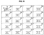
- the stator core 23 has a plurality of core sheets (in this example, twenty core sheets 23a to 23t) consisting of magnetic steel sheets, and is formed by laminating these core sheets along the radial direction of the stator 2.
- the core sheets 23a to 23t are arranged in the order such as to be directed from the inside toward the outside in the radial direction.
- Each of the core sheets 23a to 23t is formed into an H-shape, and the teeth surfaces 22 are provided at both ends of a coil winding portion 24 extending along in the axial direction.
- the coil winding portion 24 has a width that increases gradually from the inside toward the outside in the radial direction, so that when the core sheets are laminated, the teeth surface 22 side takes a trapezoidal shape.
- a first slot surface 25 and a second slot surface 26 are provided to form a slot between the adjacent pole members 21a to 21i.
- the first slot surface 25 is the side surface on the left-hand side toward the front of the pole member 21a, and faces to the second slot surface 26 of the adjacent pole member 21i (refer to FIG. 2 ).
- the second slot surface 26 is the side surface on the right-hand side toward the front of the pole member 21a, and faces to the first slot surface 25 of the adjacent pole member 21b (refer to FIG. 2 ).
- first slot surface 25 and the second slot surface 26 are asymmetrical with each other.
- the second slot surface 26 is formed with a skew for reducing cogging torque, and has a more greatly inclined surface than the first slot surface 25.
- the core sheets 23a to 23t are configured so that the width in the circumferential direction (width between the first slot surface 25 and the second slot surface 26) increases gradually from the inside toward the outside in the radial direction. That is to say, by laminating the core sheets 23a to 23t, the stator core 23 is formed into a trapezoidal shape as viewed from the front.
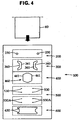
- FIG. 4 is a schematic view of a die section of a manufacturing apparatus for the axial air-gap electronic motor in accordance with one embodiment of the present invention
- FIG. 5 is a longitudinal sectional view of a main drive section of the manufacturing apparatus.
- a die is mounted on a press device, not shown.
- the specific configuration of the press device is an arbitrary item, so that the explanation thereof is omitted.
- a manufacturing apparatus 100 for the stator core is of a sequent arrangement type having a punch 110 attached to the upper part of the press device, not shown, and a die 120 attached to the lower part of the press device as the receiver side of the punch 110, and is a press molding machine of a sequentially sending type in which a mother sheet 60 (metallic sheet) consisting of a magnetic steel sheet is finished to a final molded product while sequentially sending the mother sheet 60 with fixed intervals to between the punch 110 and the die 120.
- a mother sheet 60 metal sheet
- a sheet guide (not shown) for guiding the transfer of the mother sheet 60 is provided, and a fixed stripper structure in which a fixed stripper 130 is fixed on the sheet guide is provided. Thereby, a tunnel-shaped mother sheet transfer path for transferring the mother sheet 60 is formed between the die 120 and the fixed stripper 130.
- the punch 110 and the die 120 are provided with blanking stages as described below so that the final molded product (the stator core 23) is completed after passing through the blanking stages.
- the punch 110 and the die 120 includes a pilot hole blanking stage 200 at which pilot holes 61 (refer to FIG.
- a first blanking stage 300 at which a first side surface (the first slot surface 25) in the circumferential direction of the core sheets 23a to 23t (hereinafter, a unit core sheet is denoted by 23at) of the stator core 23 is blanked out of the mother sheet 60
- a second blanking stage 400 at which a second side surface (the second slot surface 26) in the circumferential direction of the core sheet 23 is blanked out of the mother sheet 60
- a concave/convex forming stage 500 at which concave/convex portions for laminating and stakingly fixing the core sheets 23a to 23t are formed in a part of the core sheet 23, and a third blanking stage 600 at which the core sheets 23a to 23t are separated in succession from the mother sheet 60 to be laminated.
- pilot hole forming dies 240 for receiving the pilot hole forming punches 230 are attached to a die plate 150.
- a discharge hole 241 for discharging a scrap produced by the blanking work is formed on the die 120 side.
- the first blanking stage 300 is arranged on a slide base 310 that is attached to the die 120 so as to be slidable along a predetermined direction.
- a first driving means 700A for reciprocatingly sliding the slide base 310 is provided.
- the first driving means 700A is a feed screw mechanism having a servomotor 710 that is controlled by a control means, not shown, an externally threaded shaft 720 that is rotatingly driven by the servomotor 710, and a follower 730 that is fixed to the slide base 310 and converts a rotational driving force into a driving force in the right and left direction by means of an internal thread engaging with the externally threaded shaft 720.
- the first driving means 700A uses the feed screw mechanism utilizing the external thread and the internal thread.
- a rack and pinion mechanism, a linear driving mechanism, and the like may be used.
- the first driving means 700A can be changed arbitrarily according to the specifications if it can reciprocatingly move the slide base 310.
- the slide base 310 is provided with a die holder 320 that supports first dies 330, a punch holder 340 that is guided in the up and down direction by a guide post 321a erected vertically from the die holder 320 and a hanging bolt 321b, a punch plate 350 that is supported on the punch holder 340, and a pair of first punches 360 (first cutting portion) that are supported detachably on the punch plate 350.
- a stripper 370 is provided between the die holder 320 and the punch holder 340.
- compression springs 322 are attached coaxially.
- the punch holder 340 is always raised in the separating direction (the upward direction in FIG. 6 ).
- the paired right and left first punches 360 are arranged symmetrically with a predetermined clearance being provided therebetween. Since the first punches 360 have the same shape, explanation is given by taking one first punch 360 as an example.
- the first punch 360 consists of a blanking die formed into a trapezoidal shape, and on one surface thereof, a cut surface 361 for forming the first slot surface 25 is formed.
- the first punch 360 moves minutely while blanking the core sheets 23a to 23t in succession, and moves by a movement width a during the time from when blanking the first core sheet 23a to when blanking the final core sheet 23t.
- Each of the first dies 330 consists of a blanking hole the shape of which coincides with that of the first punch 360, and on the other end side (the lower side in FIG. 6 ) thereof, a discharge hole 331 for discharging a scrap produced by blanking is produced.
- the second blanking stage 400 is explained with reference to FIG. 7 .
- the second blanking stage 400 is arranged on a slide base 410 that is attached to the die 120 so as to be slidable along a predetermined direction.
- a second driving means 700B for reciprocatingly sliding the slide base 410 is provided.
- the basic configuration of the second driving means 700B is the same as that of the driving means used at the above-described first blanking stage 300, so that the explanation thereof is omitted.
- the first and second driving means 700A and 700b are controlled individually by separate systems.
- the slide base 410 is provided with a die holder 420 that supports a second die 430, a punch holder 440 that is guided in the up and down direction by a guide post 421a erected vertically from the die holder 420 and a hanging bolt 421b, a punch plate 450 that is supported on the punch holder 440, and a second punch 460 (second cutting portion) that is supported detachably on the punch plate 450. Between the die holder 420 and the punch holder 440, a stripper 470 is provided between the die holder 420 and the punch holder 440.
- the second punch 460 is formed into a trapezoidal shape, and on both surfaces thereof, a cut surface 461 for forming the second slot surface 26 is formed.
- the second punch 460 moves minutely while blanking the core sheets 23a to 23t in succession, and moves by a movement width b as a whole during the time from when blanking the first core sheet 23a to when blanking the final core sheet 23t.
- the first punches 360 are provided in a pair at the right and left to blank two sheets of the core sheets 23a to 23t at the same time, and the second punch 460 is arranged between the first punches 360.
- one first punch 360 may be provided if one sheet of the core sheets 23a to 23t is simply blanked in succession.
- the second punch 460 is arranged so as to face to the first punch 360.
- two sets of core sheets 23a-23t are preferably blanked in point symmetry.
- one second punch 460 has only to be moved reciprocatingly between two first punches 360.
- Two second punches 460 need not be provided, so that the production cost can further be reduced.
- the concave/convex forming stage 500 has a punch backing 510 attached to the punch holder 140 and a punch plate 520 attached to the punch backing 510.
- cutting punches 530 and concave/convex forming punches 530A are detachably provided on the punch 110 side.
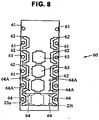
- the cutting punches 530 and the concave/convex forming punches 530A are, as shown in FIG. 4 , provided respectively at two places symmetrically in the right and left direction, at a total of four places, and are, as shown in FIG. 8 , provided so that cut holes 64 and concave/convex portions 64A are formed in a coil winding portion 24 of the core sheet 23a-23t.
- the tip end of the concave/convex forming punch 530A projects so as to be shorter than the thickness of the mother sheet 60. Therefore, by pressing the concave/convex forming punch 530A toward the mother sheet 60, a concave is formed in the top surface of the mother sheet 60, and a convex is formed in the back surface thereof along with the formation of the concave.
- two of the four concave/convex forming punches 530A are fixed to the punch plate 520, and at the other end (the upper end in FIG. 5 ) of the cutting punch 530, a knockout rod 550 is installed.
- a changeover lever 551 is provided at the rear end (the upper end in FIG. 5 ) of the cutting punch 530.
- the changeover lever 551 is provided so as to be slidable (toward the front of the paper in FIG. 5 ) by a driving means, not shown, so that the projection and retreat of the cutting punches 530 are controlled by the changeover lever 551.
- the changeover lever 551 is a lever that can change over the position of the cutting punch 530 from a projecting position to a retreating position and vice versa.
- the changeover lever 551 is supported at the retreating position, and only when the first core sheet 23a is conveyed to the concave/convex forming stage 500, the changeover lever 551 moves to the projecting position, by which the cut holes 64 are formed in the core sheet 23a. Thereby, even if the first core sheet 23a blanked next is laminated on the last core sheet 23t, these core sheets are not locked at the next third blanking stage 600.
- cutting dies 540 and concave/convex forming dies 540A for receiving the cutting punches 530 and the concave/convex forming punches 530A, respectively, are attached to a die plate 560.
- the cutting dies 540 and the concave/convex forming dies 540A are provided at four places respectively so as to face to the cutting punches 530 and the concave/convex forming punches 530A.
- a knockout rod 570 is provided to prevent the mother sheet 60 from being fitted.
- the knockout rod 570 consists of a plunger having a compression spring therein, and is provided so as to face to the concave/convex forming punches 530A not provided with the knockout rod 550. According to this configuration, the mother sheet 60 can be conveyed surely to the next third blanking stage 600.
- a punch backing 610 attached to the punch holder 140, a punch plate 620 attached to the punch backing 610, and a third punch 630 attached detachably to the punch plate 620 are provided on the punch 110 side.
- the punch backing 610 and the punch plate 620 are used in common with the punch backing 510 and the punch plate 520 at the above-described concave/convex forming stage 500.
- a knockout rod 650 On the rear end side (the upper end in FIG. 5 ) of the third punch 630, a knockout rod 650 is provided.
- the knockout rod 650 presses the concave/convex portion 64A of the core sheet 23 adjacently to the third punch 630 at the same time that twenty core sheets 23a to 23t are blanked, by which the concave/convex portions 64A of the core sheets 23a to 23t laminated on each other are engaged with each other.
- a third die 640 for receiving the third punch 630 is attached to a die plate 660.
- a discharge hole 641 for discharging the stator core 23 having been blanked and laminatedly fixed is formed on the die 120 side.
- FIG. 4 and FIG. 8 one example of a procedure for assembling the stator core for the axial air-gap electronic motor in accordance with the present invention is explained.
- the mother sheet 60 is set in the press device. Thereafter, by operating a start button, not shown, pressing work is started by a control means, not shown, in the press device.
- a control means not shown, in the press device.
- the flow direction of the mother sheet is from the upside to the downside in the same way as shown in FIG. 4 .
- the pressing work is performed at the same time at the work stages 200 to 600 by the reciprocating movement with fixed intervals of the punch 110 toward the die 120.
- the work processes of one core sheet 23a are explained for each stage in succession.
- the control means lowers the punch 110 toward the die 120 via a pressing means, not shown. Accordingly, the pilot hole forming punches 230 held by the punch plate 220 are inserted into the mother sheet 60, by which the paired pilot holes 61 are formed in the mother sheet 60.
- control means pushes out the mother sheet 60 through a predetermined length and conveys it to the next first blanking stage 300 via a conveying means, not shown. After the mother sheet 60 has been sent out, the control means lowers the punch 110.
- the first punches 360 attached to the punch plate 350 are inserted into the mother sheet 60, by which a pair of first punch holes 62 are formed on the mother sheet 60 (cutting of the first slot surface).
- the control means sends out the mother sheet 60 through a predetermined length via the conveying means, and lowers the punch 110 again.
- the control means lowers the punch 110 again.
- the second punch 460 is inserted into the mother sheet 60 along with the lowering of the punch 110.
- a second blanking hole 63 is formed in the mother sheet 60 (cutting of the second slot surface).
- the punch 110 is raised and returns to the initial position, and the mother sheet 60 is sent out to the next concave/convex forming stage 500.
- the control means lowers the punch 110.
- the concave/convex forming punches 530A are pushed into the mother sheet 60, by which the concave/convex portions 64A are formed at two places on the top and back surfaces of the coil winding portion 24 of the core sheet 23a.
- the control means changes over the changeover lever 551 for the cutting punches 530 to the projection side to form the cut holes 64 by using the cutting punches 530.
- the changeover lever 551 is moved to the retreat side, and the concave/convex portions 64A are formed on the core sheets 23b to 23t by using the concave/convex forming punches 530A.
- the mother sheet 60 is conveyed to the last third blanking stage 600, and at the same time, the punch 110 begins to lower. Thereby, the third punch 630 is inserted into the mother sheet 60, by which the core sheet 23a is separated from the mother sheet 60 (cutting of the teeth surface).
- the separated core sheet 23a is laminated on the last core sheet 23t blanked before, and at the same time, is pushed in by the third punch 630.
- the cut holes 64 are provided in the core sheet 23a in place of the concave/convex portions 64A, the core sheet 23a and the core sheet 23t are not connected to each other.
- the core sheets 23b to 23t are laminated in succession on the core sheet 23a, and are pushed in by the third punch 630 to engage the concave/convex portions 64A with each other. Thereby, the core sheets 23a to 23t are connected to each other, and thus the stator core 23 is completed.
Description
- The present invention relates to a method for manufacturing a stator core for an axial air-gap electronic motor in which a rotor and a stator are arranged opposedly along the axis direction of a rotor output shaft. More particularly, it relates to a method for manufacturing a stator core for an axial air-gap electronic motor, in which core sheets are laminated into a trapezoidal shape along the radial direction.
- For example, as shown in Japanese Patent Application Publication No.
2004-282989 - The stator has a plurality of stator cores (core members), and the stator cores are arranged in an annular shape around a bearing portion provided in the center, and are molded integrally by synthetic resin. The stator core for the axial air-gap electronic motor is formed by laminating a plurality of core sheets along the radial direction. To increase the torque, the stator core is contrived to increase the teeth area by being formed into a trapezoidal shape such that the width in the circumferential direction increases gradually from the center side to the outside.
- Also, in some stator cores, a configuration also has been proposed in which the side surface in the circumferential direction (slot surface) is provided with a skew to restrain the occurrence of cogging torque.
-
U.S. Patent No. 5,640,752 describes an adjustable method for forming and stacking laminations that are used in an electromagnetic device using two separate punches. -
JP 2006 014565 A -
JP 2004 007936 A -
DE 43 26 124 A1 describes the fabrication of structural components of an electrical machines which are fabricated automatically. - The manufacture of the stator core for the axial air-gap electronic motor has problems described below.
- In the case of the stator core for the axial air-gap electronic motor, unlike the inner rotor electronic motor, the stator cores are laminated along the radial direction. Therefore, since the teeth surface must be formed into a trapezoidal shape, the shape of core sheet must be changed one by one. Also, since the shape must be changed every one sheet, blanking dies corresponding to the number of core sheets are needed, which increases the production cost.
- Also, in order for the slot surface to take a slantwise shape, the core sheets must be laminated while shifting slightly one by one, which takes much time and labor. Further, since the core sheets are laminated in a shifted state, the positioning requires a technique.
- The present invention has been made to solve the above problems, and accordingly an object thereof is to provide a method for manufacturing a stator core for an axial air-gap electronic motor, in which core sheets are laminatedly fixed while being shifted with predetermined intervals.
- To achieve the above object, the present invention has some features described below. The present invention provides a method for manufacturing a stator core for an axial air-gap electronic motor in which a stator and a rotor are arranged opposedly along the axis line direction of a rotor output shaft, the stator core, consisting of a laminated body formed by laminating a plurality of core sheets blanked from a metallic mother sheet in the radial direction, being formed into a trapezoidal shape the circumferential width of which increases gradually from the center of the rotor output shaft toward the outside, wherein a first cutting portion for forming a first side surface (first slot surface) in the circumferential direction of the core sheet, a second cutting portion for forming a second side surface (second slot surface) in the circumferential direction of the core sheet, a first moving means for reciprocatingly moving the first cutting portion, and a second moving means for reciprocatingly moving the second cutting portion are provided, and the method includes a first blanking step in which the first slot surfaces of the first to nth (n is a positive integer) core sheets are blanked in succession out of the mother sheet by moving the first cutting portion with predetermined intervals via the first moving means on the mother sheet; and a second blanking step in which the second slot surfaces of the first to nth (n is a positive integer) core sheets are blanked in succession out of the mother sheet by moving the second cutting portion with predetermined intervals via the second moving means.
- According to this method, the width between the side surfaces (the first slot surface and the second slot surface) in the circumferential direction of the stator core can be changed by the two cutting portions moving independently, by which the stator core can be laminated without the use of a plurality of dies.
- As a more favorable mode, the first cutting portion and the second cutting portion are arranged opposedly so as to be brought close to each other or separated from each other.
- According to this method, by arranging the first cutting portion and the second cutting portion opposedly so as to be brought close to each other or separated from each other, a more space-saving die can be obtained in the case where the slot surfaces are symmetrical in the right and left direction.
- As a more favorable mode, the first cutting portion and the second cutting portion move asynchronously.
- According to this method, since the cutting portions are driven asynchronously, a core sheet in which the slot surfaces are asymmetrical in the right and left direction can be manufactured.
- Preferably, the first cutting portion is provided in a pair at the right and left with a predetermined clearance being provided therebetween, and the second cutting portion is arranged therebetween, whereby the first and second slot surfaces of two of the core sheets are blanked out of the mother sheet.
- Preferably, the stator core is assembled in point symmetry by laminating the core sheets blanked out of the mother sheet along the radial direction.
- According to this method, the second cutting portion is arranged between the paired right and left first cutting portions and these cutting portions are driven asynchronously, so that two core sheets can be manufactured at the same time. Also, by blanking the core sheets in a point symmetry shape, two second slot surfaces can be blanked at the same time by one second cutting portion. Therefore, the yield increases, and hence the productivity can further be improved.
-
-
FIG. 1 is a sectional view schematically showing an axial air-gap electronic motor manufactured by a manufacturing method in accordance with the present invention; -
FIG. 2 is a front view of a stator of the axial air-gap electronic motor shown inFIG. 1 ; -
FIG. 3A is a front view of a pole member constituting the stator shown inFIG. 2 ; -
FIG. 3B is a perspective view of a pole member constituting the stator shown inFIG. 2 ; -
FIG. 4 is a schematic view of a die section of a manufacturing apparatus for an axial air-gap electronic motor in accordance with one embodiment of the present invention; -
FIG. 5 is a main longitudinal sectional view of a drive section of a manufacturing apparatus; -
FIG. 6 is a transverse sectional view of a first blanking stage; -
FIG. 7 is a transverse sectional view of a second blanking stage; -
FIG. 8 is a front view showing a state of a mother sheet at each stage; -
FIG. 9 is an explanatory view for explaining movement of a first blanking punch and a second blanking punch; and -
FIG. 10 is a front view showing a state in which core sheets are disassembled and arranged in order from the inside diameter side to the outside diameter side. - An embodiment of the present invention will now be described with reference to the accompanying drawings.
FIG. 1 is a schematic sectional view of an axial air-gap electronic motor having a stator core, which is manufactured by a manufacturing method in accordance with one embodiment of the present invention, andFIG. 2 is a front view of a stator of the axial air-gap electronic motor shown inFIG. 1 . - The axial air-gap electronic motor 1 includes a
stator 2 formed into a disc shape and a pair ofrotors 3 arranged opposedly on both side surfaces of thestator 2 with a predetermined gap being provided therebetween. Each of therotors 3 is coaxially fixed to arotor output shaft 4 that produces a rotational driving force. - The
stator 2 and therotors 3 are housed in a bracket, not shown. In this example, the outer peripheral surface of thestator 2 is also used as the outer peripheral wall of the bracket, and at both ends thereof, a lid member, not shown, is installed. Therotors 3 may be attached directly to a fan or the like without the use of the lid member. - Although the
rotors 3 are arranged on both, right and left, sides with thestator 2 being held therebetween in this example, only either one of therotors 3 may be arranged. In the present invention, the configuration of the rotor has only to have functions necessary for constituting the axial air-gap electronic motor 1, and can be changed arbitrarily according to the specifications. - Also, although the
rotors 3 commonly use the samerotor output shaft 4 in this example, a 2-output shaft type having a rotor output shaft for each of therotors 3 may be used. Further, a shaft-less type, in which therotors 3 are directly supported on thestator 2 via radial ball bearings without the use of therotor output shaft 4, may be used. - As shown in
FIG. 2 , thestator 2 includes a plurality of (nine (nine slots) in this example)pole members 21a to 21i arranged annularly about the rotation axis of therotor output shaft 4. Each of thepole members 21a to 21i has the same construction, so that, in this example, explanation is given by taking thepole member 21a as an example. - In the central portion of the
stator 2, abearing section 2A is arranged. In this example, thebearing section 2A has a pair ofradial ball bearings rotor output shaft 4, and the outer race side is embedded in asynthetic resin material 2B that stiffens thestator 2. - As shown in the front view of
FIG. 3A and the perspective view ofFIG. 3B , thepole member 21a is formed by winding a coil, not shown, on a bobbin-shapedstator core 23 having a pair of, right and left, flange-shaped teeth surfaces 22. Thestator core 23 is formed by laminating magnetic steel sheets each formed into an H-shape along the radial direction. - The whole of the
stator core 23 excluding the teeth surfaces 22 is covered with aninsulator 5 made of an insulating resin. Theinsulator 5 hasflange portions flange portions - Each of the
flange portions pole members 21a to 21i to each other in a different mode. As a first connecting means, a lockingconvex portion 52 for connecting thepole members 21a to 21i to each other in an annular form with the axis line of therotor output shaft 4 being the center and a lockingconcave portion 53 to which the lockingconvex portion 52 is locked are provided in the end portions in the circumferential direction of theflange portions - The locking
convex portion 52 is provided so as to project from one end portion (right-hand side surface inFIG. 3A ) in the circumferential direction of theflange portions convex portion 52 consists of a tongue element formed into a triangular shape. In contrast, the lockingconcave portion 53 consists of a notch portion formed so as to be directed from the other end portion (left-hand side surface inFIG. 3A ) in the circumferential direction of theflange portions convex portion 52. - Although the locking
convex portion 52 and the lockingconcave portion 53 are formed into a triangular shape in this example, the shapes of the lockingconvex portion 52 and the lockingconcave portion 53 can be changed to an arbitrary shape such as a square shape or a semicircular shape according to the specifications if the shape is such that thepole members 21a to 21i can be connected to each other in an annular form. - According to this connecting means, by engaging the locking
convex portion 52 and the lockingconcave portion 53 with each other, thepole members 21a to 21i can be connected in an annular form with the axis line of therotor output shaft 4 being the center. - In this example, as a second connecting means, the
flange portions ribs pole members 21a to 21i in a one-row rod form. However, since the second connecting means is an arbitrary item in the present invention, the explanation thereof is omitted. - As shown in
FIG. 10 , thestator core 23 has a plurality of core sheets (in this example, twentycore sheets 23a to 23t) consisting of magnetic steel sheets, and is formed by laminating these core sheets along the radial direction of thestator 2. In this example, thecore sheets 23a to 23t are arranged in the order such as to be directed from the inside toward the outside in the radial direction. - Each of the
core sheets 23a to 23t is formed into an H-shape, and the teeth surfaces 22 are provided at both ends of acoil winding portion 24 extending along in the axial direction. As shown inFIG. 10 , thecoil winding portion 24 has a width that increases gradually from the inside toward the outside in the radial direction, so that when the core sheets are laminated, the teeth surface 22 side takes a trapezoidal shape. - As shown in
FIGS. 2 and3 , at both ends (inFIG. 10 , both ends at the right and left direction) in the circumferential direction of the teeth surface 22, afirst slot surface 25 and asecond slot surface 26 are provided to form a slot between theadjacent pole members 21a to 21i. - In
FIG. 3 , thefirst slot surface 25 is the side surface on the left-hand side toward the front of thepole member 21a, and faces to thesecond slot surface 26 of theadjacent pole member 21i (refer toFIG. 2 ). Thesecond slot surface 26 is the side surface on the right-hand side toward the front of thepole member 21a, and faces to thefirst slot surface 25 of theadjacent pole member 21b (refer toFIG. 2 ). - In this example, the
first slot surface 25 and thesecond slot surface 26 are asymmetrical with each other. Thesecond slot surface 26 is formed with a skew for reducing cogging torque, and has a more greatly inclined surface than thefirst slot surface 25. - The
core sheets 23a to 23t are configured so that the width in the circumferential direction (width between thefirst slot surface 25 and the second slot surface 26) increases gradually from the inside toward the outside in the radial direction. That is to say, by laminating thecore sheets 23a to 23t, thestator core 23 is formed into a trapezoidal shape as viewed from the front. - Next, a manufacturing apparatus for manufacturing the
stator core 23 is explained.FIG. 4 is a schematic view of a die section of a manufacturing apparatus for the axial air-gap electronic motor in accordance with one embodiment of the present invention, andFIG. 5 is a longitudinal sectional view of a main drive section of the manufacturing apparatus. A die is mounted on a press device, not shown. In the present invention, the specific configuration of the press device is an arbitrary item, so that the explanation thereof is omitted. - As shown in
FIGS. 4 and5 , amanufacturing apparatus 100 for the stator core is of a sequent arrangement type having apunch 110 attached to the upper part of the press device, not shown, and adie 120 attached to the lower part of the press device as the receiver side of thepunch 110, and is a press molding machine of a sequentially sending type in which a mother sheet 60 (metallic sheet) consisting of a magnetic steel sheet is finished to a final molded product while sequentially sending themother sheet 60 with fixed intervals to between thepunch 110 and thedie 120. - Above the
die 120, a sheet guide (not shown) for guiding the transfer of themother sheet 60 is provided, and a fixed stripper structure in which a fixedstripper 130 is fixed on the sheet guide is provided. Thereby, a tunnel-shaped mother sheet transfer path for transferring themother sheet 60 is formed between the die 120 and the fixedstripper 130. - The
punch 110 and thedie 120 are provided with blanking stages as described below so that the final molded product (the stator core 23) is completed after passing through the blanking stages. Specifically, thepunch 110 and thedie 120 includes a pilothole blanking stage 200 at which pilot holes 61 (refer toFIG. 8 ) serving as a reference guide for blanking are formed in themother sheet 60, afirst blanking stage 300 at which a first side surface (the first slot surface 25) in the circumferential direction of thecore sheets 23a to 23t (hereinafter, a unit core sheet is denoted by 23at) of thestator core 23 is blanked out of themother sheet 60, asecond blanking stage 400 at which a second side surface (the second slot surface 26) in the circumferential direction of thecore sheet 23 is blanked out of themother sheet 60, a concave/convex formingstage 500 at which concave/convex portions for laminating and stakingly fixing thecore sheets 23a to 23t are formed in a part of thecore sheet 23, and athird blanking stage 600 at which thecore sheets 23a to 23t are separated in succession from themother sheet 60 to be laminated. - Referring to
FIG. 5 , at the pilothole blanking stage 200, apunch backing 210 attached to apunch holder 140 that is attached so as to be capable of being reciprocatingly moved up and down by a press driving means, not shown, apunch plate 220 attached to thepunch backing 210, and pilothole forming punches 230 attached detachably to thepunch plate 220 are provided on thepunch 110 side. - On the
die 120 side, pilot hole forming dies 240 for receiving the pilothole forming punches 230 are attached to adie plate 150. On the rear end side of the pilot hole forming die 240 (on the lower end side inFIG. 5 ), adischarge hole 241 for discharging a scrap produced by the blanking work is formed. - Next, referring additionally to
FIG. 6 , thefirst blanking stage 300 is explained. Thefirst blanking stage 300 is arranged on aslide base 310 that is attached to the die 120 so as to be slidable along a predetermined direction. At one end of theslide base 310, a first driving means 700A for reciprocatingly sliding theslide base 310 is provided. - The first driving means 700A is a feed screw mechanism having a
servomotor 710 that is controlled by a control means, not shown, an externally threadedshaft 720 that is rotatingly driven by theservomotor 710, and afollower 730 that is fixed to theslide base 310 and converts a rotational driving force into a driving force in the right and left direction by means of an internal thread engaging with the externally threadedshaft 720. - In this example, the first driving means 700A uses the feed screw mechanism utilizing the external thread and the internal thread. However, besides, a rack and pinion mechanism, a linear driving mechanism, and the like may be used. The first driving means 700A can be changed arbitrarily according to the specifications if it can reciprocatingly move the
slide base 310. - The
slide base 310 is provided with adie holder 320 that supports first dies 330, apunch holder 340 that is guided in the up and down direction by aguide post 321a erected vertically from thedie holder 320 and a hangingbolt 321b, apunch plate 350 that is supported on thepunch holder 340, and a pair of first punches 360 (first cutting portion) that are supported detachably on thepunch plate 350. Between thedie holder 320 and thepunch holder 340, astripper 370 is provided. - To the
guide post 321a, compression springs 322 are attached coaxially. By the compression springs 322, thepunch holder 340 is always raised in the separating direction (the upward direction inFIG. 6 ). - As shown in
FIG. 9 , the paired right and leftfirst punches 360 are arranged symmetrically with a predetermined clearance being provided therebetween. Since thefirst punches 360 have the same shape, explanation is given by taking onefirst punch 360 as an example. - The
first punch 360 consists of a blanking die formed into a trapezoidal shape, and on one surface thereof, acut surface 361 for forming thefirst slot surface 25 is formed. In this example, to form the inclined surface of thefirst slot surface 25, thefirst punch 360 moves minutely while blanking thecore sheets 23a to 23t in succession, and moves by a movement width a during the time from when blanking thefirst core sheet 23a to when blanking thefinal core sheet 23t. - Each of the first dies 330 consists of a blanking hole the shape of which coincides with that of the
first punch 360, and on the other end side (the lower side inFIG. 6 ) thereof, adischarge hole 331 for discharging a scrap produced by blanking is produced. - Next, the
second blanking stage 400 is explained with reference toFIG. 7 . Thesecond blanking stage 400 is arranged on aslide base 410 that is attached to the die 120 so as to be slidable along a predetermined direction. At one end of theslide base 410, a second driving means 700B for reciprocatingly sliding theslide base 410 is provided. - The basic configuration of the second driving means 700B is the same as that of the driving means used at the above-described first blanking
stage 300, so that the explanation thereof is omitted. The first and second driving means 700A and 700b are controlled individually by separate systems. - The
slide base 410 is provided with adie holder 420 that supports asecond die 430, apunch holder 440 that is guided in the up and down direction by aguide post 421a erected vertically from thedie holder 420 and a hangingbolt 421b, apunch plate 450 that is supported on thepunch holder 440, and a second punch 460 (second cutting portion) that is supported detachably on thepunch plate 450. Between thedie holder 420 and thepunch holder 440, astripper 470 is provided. - As shown in
FIG. 9 , thesecond punch 460 is formed into a trapezoidal shape, and on both surfaces thereof, acut surface 461 for forming thesecond slot surface 26 is formed. In this example, to form the inclined surface of thesecond slot surface 26, thesecond punch 460 moves minutely while blanking thecore sheets 23a to 23t in succession, and moves by a movement width b as a whole during the time from when blanking thefirst core sheet 23a to when blanking thefinal core sheet 23t. - In this example, the
first punches 360 are provided in a pair at the right and left to blank two sheets of thecore sheets 23a to 23t at the same time, and thesecond punch 460 is arranged between the first punches 360. In an alternative example, onefirst punch 360 may be provided if one sheet of thecore sheets 23a to 23t is simply blanked in succession. In this case, thesecond punch 460 is arranged so as to face to thefirst punch 360. - As a more favorable mode, two sets of
core sheets 23a-23t are preferably blanked in point symmetry. Specifically, as shown inFIG. 9 , by arranging thecore sheets 23a-23t at a point symmetry position, onesecond punch 460 has only to be moved reciprocatingly between twofirst punches 360. Twosecond punches 460 need not be provided, so that the production cost can further be reduced. - Referring again to
FIG. 5 , the concave/convex formingstage 500 is explained. The concave/convex formingstage 500 has a punch backing 510 attached to thepunch holder 140 and a punch plate 520 attached to the punch backing 510. In the punch plate 520, cuttingpunches 530 and concave/convex formingpunches 530A are detachably provided on thepunch 110 side. - The cutting punches 530 and the concave/convex forming
punches 530A are, as shown inFIG. 4 , provided respectively at two places symmetrically in the right and left direction, at a total of four places, and are, as shown inFIG. 8 , provided so that cut holes 64 and concave/convex portions 64A are formed in acoil winding portion 24 of thecore sheet 23a-23t. - The tip end of the concave/convex forming
punch 530A projects so as to be shorter than the thickness of themother sheet 60. Therefore, by pressing the concave/convex formingpunch 530A toward themother sheet 60, a concave is formed in the top surface of themother sheet 60, and a convex is formed in the back surface thereof along with the formation of the concave. - In this example, two of the four concave/convex forming
punches 530A are fixed to the punch plate 520, and at the other end (the upper end inFIG. 5 ) of the cuttingpunch 530, aknockout rod 550 is installed. - At the rear end (the upper end in
FIG. 5 ) of the cuttingpunch 530, achangeover lever 551 is provided. Thechangeover lever 551 is provided so as to be slidable (toward the front of the paper inFIG. 5 ) by a driving means, not shown, so that the projection and retreat of the cutting punches 530 are controlled by thechangeover lever 551. - The
changeover lever 551 is a lever that can change over the position of the cuttingpunch 530 from a projecting position to a retreating position and vice versa. Usually, thechangeover lever 551 is supported at the retreating position, and only when thefirst core sheet 23a is conveyed to the concave/convex formingstage 500, thechangeover lever 551 moves to the projecting position, by which the cut holes 64 are formed in thecore sheet 23a. Thereby, even if thefirst core sheet 23a blanked next is laminated on thelast core sheet 23t, these core sheets are not locked at the nextthird blanking stage 600. - On the
die 120 side, cutting dies 540 and concave/convex forming dies 540A for receiving the cutting punches 530 and the concave/convex formingpunches 530A, respectively, are attached to a die plate 560. The cutting dies 540 and the concave/convex forming dies 540A are provided at four places respectively so as to face to the cutting punches 530 and the concave/convex formingpunches 530A. In the concave/convex formingdie 540A, aknockout rod 570 is provided to prevent themother sheet 60 from being fitted. - The
knockout rod 570 consists of a plunger having a compression spring therein, and is provided so as to face to the concave/convex formingpunches 530A not provided with theknockout rod 550. According to this configuration, themother sheet 60 can be conveyed surely to the nextthird blanking stage 600. - Referring to
FIG. 5 , at thethird blanking stage 600, a punch backing 610 attached to thepunch holder 140, a punch plate 620 attached to the punch backing 610, and athird punch 630 attached detachably to the punch plate 620 are provided on thepunch 110 side. - In this example, the punch backing 610 and the punch plate 620 are used in common with the punch backing 510 and the punch plate 520 at the above-described concave/convex forming
stage 500. - On the rear end side (the upper end in
FIG. 5 ) of thethird punch 630, aknockout rod 650 is provided. Theknockout rod 650 presses the concave/convex portion 64A of thecore sheet 23 adjacently to thethird punch 630 at the same time that twentycore sheets 23a to 23t are blanked, by which the concave/convex portions 64A of thecore sheets 23a to 23t laminated on each other are engaged with each other. - On the
die 120 side, athird die 640 for receiving thethird punch 630 is attached to a die plate 660. On the rear end side (the lower end side inFIG. 5 ) of thethird die 640, adischarge hole 641 for discharging thestator core 23 having been blanked and laminatedly fixed is formed. - Next, referring to
FIG. 4 andFIG. 8 , one example of a procedure for assembling the stator core for the axial air-gap electronic motor in accordance with the present invention is explained. First, themother sheet 60 is set in the press device. Thereafter, by operating a start button, not shown, pressing work is started by a control means, not shown, in the press device. InFIG. 8 , the flow direction of the mother sheet is from the upside to the downside in the same way as shown inFIG. 4 . - The pressing work is performed at the same time at the work stages 200 to 600 by the reciprocating movement with fixed intervals of the
punch 110 toward thedie 120. However, hereunder, for convenience of explanation, the work processes of onecore sheet 23a are explained for each stage in succession. - First, when the
mother sheet 60 is conveyed to the pilothole blanking stage 200, the control means lowers thepunch 110 toward thedie 120 via a pressing means, not shown. Accordingly, the pilothole forming punches 230 held by thepunch plate 220 are inserted into themother sheet 60, by which the pairedpilot holes 61 are formed in themother sheet 60. - When the pilot
hole forming punches 230 are raised and return to the initial positions, the control means pushes out themother sheet 60 through a predetermined length and conveys it to the nextfirst blanking stage 300 via a conveying means, not shown. After themother sheet 60 has been sent out, the control means lowers thepunch 110. - With the lowering of the
punch 110, at thefirst blanking stage 300, thefirst punches 360 attached to thepunch plate 350 are inserted into themother sheet 60, by which a pair of first punch holes 62 are formed on the mother sheet 60 (cutting of the first slot surface). - When the
first punches 360 are raised and thepunch 110 returns to the initial position, the control means sends out themother sheet 60 through a predetermined length via the conveying means, and lowers thepunch 110 again. At the same time, the control means gives a command to thedrive motor 710 of the first driving means 700 to move thefirst punches 360 by a movement amount Δa (= a/20) corresponding to one sheet of thecore sheets 23a to 23t. Thereby, preparations are made for thesecond core sheet 23b to be blanked next. - Subsequently, the control means lowers the
punch 110 again. Along with this operation, at thesecond blanking stage 400, thesecond punch 460 is inserted into themother sheet 60 along with the lowering of thepunch 110. Thereby, asecond blanking hole 63 is formed in the mother sheet 60 (cutting of the second slot surface). - When the blanking work of the
second blanking hole 63 is finished, thepunch 110 is raised and returns to the initial position, and themother sheet 60 is sent out to the next concave/convex formingstage 500. At the same time, the control means gives a command to the second driving means 700 of thethird blanking stage 400 to move thesecond punch 460 by a movement amount Δb (= b/20) corresponding to one sheet of thecore sheets 23a to 23t. Thereby, preparations are made for thesecond core sheet 23b to be blanked next. - Checking that the
mother sheet 60 has been conveyed to the concave/convex formingstage 500, the control means lowers thepunch 110. Thereby, the concave/convex formingpunches 530A are pushed into themother sheet 60, by which the concave/convex portions 64A are formed at two places on the top and back surfaces of thecoil winding portion 24 of thecore sheet 23a. - When judging that the first core sheet, in this example, the
core sheet 23a has been conveyed, the control means changes over thechangeover lever 551 for the cutting punches 530 to the projection side to form the cut holes 64 by using the cutting punches 530. When the subsequent blanking work for thecore sheets 23b to 23t is performed, thechangeover lever 551 is moved to the retreat side, and the concave/convex portions 64A are formed on thecore sheets 23b to 23t by using the concave/convex formingpunches 530A. - After the concave/
convex portions 64A have been formed, themother sheet 60 is conveyed to the lastthird blanking stage 600, and at the same time, thepunch 110 begins to lower. Thereby, thethird punch 630 is inserted into themother sheet 60, by which thecore sheet 23a is separated from the mother sheet 60 (cutting of the teeth surface). - The separated
core sheet 23a is laminated on thelast core sheet 23t blanked before, and at the same time, is pushed in by thethird punch 630. However, since the cut holes 64 are provided in thecore sheet 23a in place of the concave/convex portions 64A, thecore sheet 23a and thecore sheet 23t are not connected to each other. - A series of the work processes is repeated. The
core sheets 23b to 23t are laminated in succession on thecore sheet 23a, and are pushed in by thethird punch 630 to engage the concave/convex portions 64A with each other. Thereby, thecore sheets 23a to 23t are connected to each other, and thus thestator core 23 is completed.
Claims (2)
- A method for manufacturing a stator core (23) for an axial air-gap electronic motor (1) in which a stator (2) and a rotor (3) are arranged opposedly along the axis line direction of a rotor output shaft (4), said stator (2) comprising a plurality of pole members (21a-21i) disposed about a rotation axis of the rotor output shaft (4), each of said pole members (21a-21i) including a stator core (23) for forming the axial air-gap electronic motor (1), said stator core (23), consisting of a laminated body formed by laminating a plurality of core sheets (23a-23t) which are blanked from a metallic sheet (60) in a radial direction of the stator (2) to form a trapezoidal shape of the stator core (23) in which the width of the stator core (23) in a circumferential direction about the stator (2) increases from a center of the rotor output shaft (4) toward the outside,
characterised by the method comprising:forming, with first punches (360), a first slot surface (25) on one side in the circumferential direction of each of the core sheets (23a-23t);forming, with a second punch (460), a second slot surface (26) on an other side of the said one side in the circumferential direction of each of the core sheets (23a-23t);reciprocatingly moving, with a first moving means (700A), the first punches (360);reciprocatingly moving, with a second moving means (700B), the second punch (460),wherein the first punches (360) are provided in a pair with a predetermined clearance being provided therebetween, and the second punch (460) is arranged between the pair,wherein the method further comprises:a first blanking step (300) in which the first slot surfaces (25) of the first to nth (n is a positive integer) core sheets are blanked in succession out of the metallic sheet (60) by moving the first punches (360); anda second blanking step (400) in which the second slot surfaces (26) of the first to nth (n is a positive integer) core sheets are blanked in succession out of the metallic sheet (60) by moving the second punch (460) at predetermined intervals. - The method for manufacturing a stator core for an axial air-gap electronic motor according to claim 1, wherein, by means of said first punches (360) arranged in the pair and said second punch (460) disposed between said pair, two sets of the stator cores (23a-23t, 23t-23a) are assembled in point symmetry by laminating the core sheets blanked out of the metallic sheet (60) along the radial direction.
Applications Claiming Priority (1)
| Application Number | Priority Date | Filing Date | Title |
|---|---|---|---|
| JP2006070580A JP4834433B2 (en) | 2006-03-15 | 2006-03-15 | Manufacturing method of stator core for axial air gap type motor |
Publications (2)
| Publication Number | Publication Date |
|---|---|
| EP1835599A1 EP1835599A1 (en) | 2007-09-19 |
| EP1835599B1 true EP1835599B1 (en) | 2017-09-27 |
Family
ID=38181133
Family Applications (1)
| Application Number | Title | Priority Date | Filing Date |
|---|---|---|---|
| EP07251072.0A Active EP1835599B1 (en) | 2006-03-15 | 2007-03-14 | Method for manufacturing a stator core of an axial air-gap motor |
Country Status (6)
| Country | Link |
|---|---|
| US (1) | US8042257B2 (en) |
| EP (1) | EP1835599B1 (en) |
| JP (1) | JP4834433B2 (en) |
| KR (1) | KR101257358B1 (en) |
| CN (1) | CN101039055B (en) |
| TW (1) | TWI427896B (en) |
Families Citing this family (17)
| Publication number | Priority date | Publication date | Assignee | Title |
|---|---|---|---|---|
| JP5311290B2 (en) * | 2009-09-07 | 2013-10-09 | ダイキン工業株式会社 | Manufacturing method of stator core for axial gap type rotating electrical machine |
| JP4730461B2 (en) * | 2009-09-25 | 2011-07-20 | ダイキン工業株式会社 | Magnetic core manufacturing method |
| KR101134969B1 (en) * | 2009-11-19 | 2012-04-09 | 현대자동차주식회사 | Method for manufacturing stator for electric water pump |
| WO2011084530A2 (en) * | 2009-12-16 | 2011-07-14 | Clear Path Energy, Llc | Floating underwater support structure |
| US9270150B2 (en) | 2009-12-16 | 2016-02-23 | Clear Path Energy, Llc | Axial gap rotating electrical machine |
| JP5403260B2 (en) * | 2009-12-22 | 2014-01-29 | ダイキン工業株式会社 | Manufacturing method of stator core for axial gap type rotating electrical machine |
| JP5495180B2 (en) * | 2010-01-22 | 2014-05-21 | ダイキン工業株式会社 | Manufacturing method of rotor core for axial gap type rotating electrical machine |
| JP5454164B2 (en) * | 2010-01-22 | 2014-03-26 | ダイキン工業株式会社 | Rotor core for axial gap type rotating electrical machine and manufacturing method thereof |
| US9178403B2 (en) * | 2010-09-29 | 2015-11-03 | Honda Motor Co., Ltd. | Laminated body manufacturing method |
| DE102010060482B4 (en) * | 2010-11-10 | 2017-07-13 | Binova Gmbh | Electric pancake motor and electric bicycle or pedelec with a pancake motor |
| JP5957360B2 (en) * | 2012-10-23 | 2016-07-27 | 株式会社三井ハイテック | Manufacturing method of laminated iron core |
| JP5815760B2 (en) * | 2014-01-17 | 2015-11-17 | ファナック株式会社 | Motor having non-circular stator core, motor manufacturing apparatus, and motor manufacturing method |
| CN106464041B (en) * | 2014-04-25 | 2019-06-07 | 株式会社日立产机系统 | Axail air gap type rotating electric machine |
| CN105469974B (en) * | 2015-12-21 | 2017-09-15 | 湖北建鑫传动轴有限公司 | A kind of pole piece mould |
| JP6778497B2 (en) * | 2016-03-22 | 2020-11-04 | 株式会社三井ハイテック | Manufacturing method of laminated iron core and its manufacturing equipment |
| CN107317407B (en) * | 2016-04-27 | 2019-02-15 | 东元电机股份有限公司 | Group connects the modular motor stator and its manufacturing method of multiple monodentate components |
| US11658530B2 (en) | 2021-07-15 | 2023-05-23 | Stoneridge, Inc. | Modular brushless DC (BLDC) motor construction |
Family Cites Families (16)
| Publication number | Priority date | Publication date | Assignee | Title |
|---|---|---|---|---|
| US2557249A (en) * | 1946-09-07 | 1951-06-19 | Gen Mills Inc | Stator for induction motors |
| US2495218A (en) * | 1946-09-28 | 1950-01-24 | Gen Mills Inc | Section for stator cores for induction motors |
| DE4326124C2 (en) | 1993-08-04 | 1996-07-18 | Wolfgang Hill | Multi-phase electrical machine |
| US5604971A (en) * | 1993-09-30 | 1997-02-25 | Steiner; Robert E. | manufacturing method for variable laminations used in electro-magnetic induction devices |
| US5640752A (en) | 1993-09-30 | 1997-06-24 | Steiner; Robert E. | Controlled adjustable manufacturing method for variable laminations used in electro-magnetic induction devices |
| JPH10156593A (en) * | 1996-11-29 | 1998-06-16 | Aida Eng Ltd | Die set device for press machine |
| JP2000033433A (en) * | 1998-07-22 | 2000-02-02 | Hoden Seimitsu Kako Kenkyusho Ltd | Manufacture of laminated body |
| JP2001102234A (en) * | 1999-09-30 | 2001-04-13 | Hitachi Ltd | Method for manufacturing laminated iron core |
| JP4121008B2 (en) * | 2001-07-03 | 2008-07-16 | 三菱電機株式会社 | Stator and manufacturing method thereof, and stator core member manufacturing apparatus |
| JP3777435B2 (en) | 2002-04-08 | 2006-05-24 | 株式会社一宮電機 | Manufacturing method of motor core and motor core |
| JP4003058B2 (en) * | 2002-07-17 | 2007-11-07 | 株式会社富士通ゼネラル | Induction motor |
| CN1225073C (en) * | 2002-10-30 | 2005-10-26 | 周万顺 | Manufacturing method of rotor for use in minitype motor |
| JP4305649B2 (en) * | 2003-02-26 | 2009-07-29 | 株式会社富士通ゼネラル | Axial gap type electric motor |
| JP2005051929A (en) * | 2003-07-29 | 2005-02-24 | Fujitsu General Ltd | Motor |
| JP2006014565A (en) | 2004-06-29 | 2006-01-12 | Nissan Motor Co Ltd | Disc type rotary electric machine |
| JP4574255B2 (en) * | 2004-07-13 | 2010-11-04 | 黒田精工株式会社 | Manufacturing method of split laminated core and progressive mold for manufacturing |
-
2006
- 2006-03-15 JP JP2006070580A patent/JP4834433B2/en active Active
-
2007
- 2007-03-13 US US11/717,079 patent/US8042257B2/en active Active
- 2007-03-14 TW TW096108758A patent/TWI427896B/en active
- 2007-03-14 EP EP07251072.0A patent/EP1835599B1/en active Active
- 2007-03-14 KR KR1020070025056A patent/KR101257358B1/en active IP Right Grant
- 2007-03-15 CN CN2007100863932A patent/CN101039055B/en active Active
Non-Patent Citations (1)
| Title |
|---|
| None * |
Also Published As
| Publication number | Publication date |
|---|---|
| TW200818661A (en) | 2008-04-16 |
| CN101039055A (en) | 2007-09-19 |
| CN101039055B (en) | 2012-05-30 |
| JP4834433B2 (en) | 2011-12-14 |
| US20070214632A1 (en) | 2007-09-20 |
| KR101257358B1 (en) | 2013-04-23 |
| EP1835599A1 (en) | 2007-09-19 |
| KR20070093900A (en) | 2007-09-19 |
| TWI427896B (en) | 2014-02-21 |
| US8042257B2 (en) | 2011-10-25 |
| JP2007252064A (en) | 2007-09-27 |
Similar Documents
| Publication | Publication Date | Title |
|---|---|---|
| EP1835599B1 (en) | Method for manufacturing a stator core of an axial air-gap motor | |
| US4622835A (en) | Apparatus and method for continuously forming edgewise wound cores | |
| US11524327B2 (en) | Device for manufacturing laminated iron core and method for manufacturing laminated iron core | |
| US20080047131A1 (en) | Die assembly and method for manufacturing lamina stacks from a plurality of separate strips of stock material | |
| CN107086731B (en) | Method and apparatus for manufacturing laminated core | |
| US5539974A (en) | Method for producing laminated iron cores | |
| US20190372439A1 (en) | Method of manufacturing stacked core and apparatus for manufacturing stacked core | |
| US4914934A (en) | Method of forming an edgewise wound core | |
| CA2758405A1 (en) | Process and mold for producing ferromagnetic cores of electric motors | |
| JPH06133501A (en) | Laminated stator core for motor and manufacture thereof | |
| KR100235830B1 (en) | Motor core | |
| US7086317B2 (en) | Method for manufacturing linear motor lamination | |
| JP3786924B2 (en) | Laminate core manufacturing equipment | |
| KR20160023399A (en) | Progressive mold for manufacturing core of rotator or stator | |
| EP0198047B1 (en) | Lanced strip arrangement | |
| JP4766774B2 (en) | Laminate core manufacturing equipment | |
| US4726209A (en) | Method of forming edgewise wound cores | |
| JP5421149B2 (en) | Manufacturing method of laminated iron core | |
| JP2767062B2 (en) | Punching method and punching die for motor core | |
| US4918962A (en) | Apparatus and method for forming edgewise wound cores | |
| JP6316783B2 (en) | Manufacturing method and manufacturing apparatus of laminated iron core | |
| JP2001105045A (en) | Laminated and bonded article | |
| KR100497528B1 (en) | Core for linear motor and manufacturing method thereof | |
| KR20100013603A (en) | Indexing apparatus for manufacturing stack of laminae | |
| JPH1080732A (en) | Punching device |
Legal Events
| Date | Code | Title | Description |
|---|---|---|---|
| PUAI | Public reference made under article 153(3) epc to a published international application that has entered the european phase |
Free format text: ORIGINAL CODE: 0009012 |
|
| AK | Designated contracting states |
Kind code of ref document: A1 Designated state(s): AT BE BG CH CY CZ DE DK EE ES FI FR GB GR HU IE IS IT LI LT LU LV MC MT NL PL PT RO SE SI SK TR |
|
| AX | Request for extension of the european patent |
Extension state: AL BA HR MK YU |
|
| 17P | Request for examination filed |
Effective date: 20080227 |
|
| 17Q | First examination report despatched |
Effective date: 20080410 |
|
| AKX | Designation fees paid |
Designated state(s): DE FR GB IT |
|
| GRAP | Despatch of communication of intention to grant a patent |
Free format text: ORIGINAL CODE: EPIDOSNIGR1 |
|
| INTG | Intention to grant announced |
Effective date: 20170309 |
|
| GRAJ | Information related to disapproval of communication of intention to grant by the applicant or resumption of examination proceedings by the epo deleted |
Free format text: ORIGINAL CODE: EPIDOSDIGR1 |
|
| GRAL | Information related to payment of fee for publishing/printing deleted |
Free format text: ORIGINAL CODE: EPIDOSDIGR3 |
|
| GRAS | Grant fee paid |
Free format text: ORIGINAL CODE: EPIDOSNIGR3 |
|
| GRAR | Information related to intention to grant a patent recorded |
Free format text: ORIGINAL CODE: EPIDOSNIGR71 |
|
| GRAA | (expected) grant |
Free format text: ORIGINAL CODE: 0009210 |
|
| INTC | Intention to grant announced (deleted) | ||
| INTG | Intention to grant announced |
Effective date: 20170810 |
|
| RIN1 | Information on inventor provided before grant (corrected) |
Inventor name: KOJIMA, TOMONORI Inventor name: KURITA, HITOSHI Inventor name: TOSU, NORIO Inventor name: IGARASHI, HISAO |
|
| AK | Designated contracting states |
Kind code of ref document: B1 Designated state(s): DE FR GB IT |
|
| REG | Reference to a national code |
Ref country code: GB Ref legal event code: FG4D |
|
| REG | Reference to a national code |
Ref country code: DE Ref legal event code: R096 Ref document number: 602007052473 Country of ref document: DE |
|
| REG | Reference to a national code |
Ref country code: FR Ref legal event code: PLFP Year of fee payment: 12 |
|
| REG | Reference to a national code |
Ref country code: DE Ref legal event code: R097 Ref document number: 602007052473 Country of ref document: DE |
|
| PLBE | No opposition filed within time limit |
Free format text: ORIGINAL CODE: 0009261 |
|
| STAA | Information on the status of an ep patent application or granted ep patent |
Free format text: STATUS: NO OPPOSITION FILED WITHIN TIME LIMIT |
|
| 26N | No opposition filed |
Effective date: 20180628 |
|
| PGFP | Annual fee paid to national office [announced via postgrant information from national office to epo] |
Ref country code: FR Payment date: 20230208 Year of fee payment: 17 |
|
| PGFP | Annual fee paid to national office [announced via postgrant information from national office to epo] |
Ref country code: IT Payment date: 20230213 Year of fee payment: 17 Ref country code: GB Payment date: 20230202 Year of fee payment: 17 Ref country code: DE Payment date: 20230131 Year of fee payment: 17 |