EP1835547A1 - Photovoltaic module - Google Patents
Photovoltaic module Download PDFInfo
- Publication number
- EP1835547A1 EP1835547A1 EP04821428A EP04821428A EP1835547A1 EP 1835547 A1 EP1835547 A1 EP 1835547A1 EP 04821428 A EP04821428 A EP 04821428A EP 04821428 A EP04821428 A EP 04821428A EP 1835547 A1 EP1835547 A1 EP 1835547A1
- Authority
- EP
- European Patent Office
- Prior art keywords
- panel
- silicate glass
- lenses
- fresnel lenses
- photovoltaic module
- Prior art date
- Legal status (The legal status is an assumption and is not a legal conclusion. Google has not performed a legal analysis and makes no representation as to the accuracy of the status listed.)
- Granted
Links
- 239000005368 silicate glass Substances 0.000 claims abstract description 41
- 229910052751 metal Inorganic materials 0.000 claims description 52
- 239000002184 metal Substances 0.000 claims description 52
- 230000003287 optical effect Effects 0.000 claims description 13
- 230000005855 radiation Effects 0.000 abstract description 8
- 239000011521 glass Substances 0.000 description 23
- 239000010410 layer Substances 0.000 description 11
- 229920001296 polysiloxane Polymers 0.000 description 11
- 239000004744 fabric Substances 0.000 description 9
- 230000007613 environmental effect Effects 0.000 description 5
- 239000004065 semiconductor Substances 0.000 description 4
- 238000010276 construction Methods 0.000 description 3
- 239000012945 sealing adhesive Substances 0.000 description 3
- VYPSYNLAJGMNEJ-UHFFFAOYSA-N Silicium dioxide Chemical compound O=[Si]=O VYPSYNLAJGMNEJ-UHFFFAOYSA-N 0.000 description 2
- XUIMIQQOPSSXEZ-UHFFFAOYSA-N Silicon Chemical compound [Si] XUIMIQQOPSSXEZ-UHFFFAOYSA-N 0.000 description 2
- 238000006243 chemical reaction Methods 0.000 description 2
- 239000012141 concentrate Substances 0.000 description 2
- 230000001186 cumulative effect Effects 0.000 description 2
- 230000000694 effects Effects 0.000 description 2
- 238000010438 heat treatment Methods 0.000 description 2
- 230000007774 longterm Effects 0.000 description 2
- 238000004519 manufacturing process Methods 0.000 description 2
- 239000000463 material Substances 0.000 description 2
- 230000001681 protective effect Effects 0.000 description 2
- 239000011241 protective layer Substances 0.000 description 2
- 229910052710 silicon Inorganic materials 0.000 description 2
- 239000010703 silicon Substances 0.000 description 2
- BPQQTUXANYXVAA-UHFFFAOYSA-N Orthosilicate Chemical compound [O-][Si]([O-])([O-])[O-] BPQQTUXANYXVAA-UHFFFAOYSA-N 0.000 description 1
- 238000010521 absorption reaction Methods 0.000 description 1
- 229910052782 aluminium Inorganic materials 0.000 description 1
- XAGFODPZIPBFFR-UHFFFAOYSA-N aluminium Chemical compound [Al] XAGFODPZIPBFFR-UHFFFAOYSA-N 0.000 description 1
- 238000005452 bending Methods 0.000 description 1
- 230000007423 decrease Effects 0.000 description 1
- 230000003247 decreasing effect Effects 0.000 description 1
- 239000000428 dust Substances 0.000 description 1
- 238000010292 electrical insulation Methods 0.000 description 1
- 238000005538 encapsulation Methods 0.000 description 1
- 238000004146 energy storage Methods 0.000 description 1
- 238000000034 method Methods 0.000 description 1
- 238000010327 methods by industry Methods 0.000 description 1
- 230000005693 optoelectronics Effects 0.000 description 1
- 238000003825 pressing Methods 0.000 description 1
Images


Classifications
-
- H—ELECTRICITY
- H01—ELECTRIC ELEMENTS
- H01L—SEMICONDUCTOR DEVICES NOT COVERED BY CLASS H10
- H01L31/00—Semiconductor devices sensitive to infrared radiation, light, electromagnetic radiation of shorter wavelength or corpuscular radiation and specially adapted either for the conversion of the energy of such radiation into electrical energy or for the control of electrical energy by such radiation; Processes or apparatus specially adapted for the manufacture or treatment thereof or of parts thereof; Details thereof
- H01L31/04—Semiconductor devices sensitive to infrared radiation, light, electromagnetic radiation of shorter wavelength or corpuscular radiation and specially adapted either for the conversion of the energy of such radiation into electrical energy or for the control of electrical energy by such radiation; Processes or apparatus specially adapted for the manufacture or treatment thereof or of parts thereof; Details thereof adapted as photovoltaic [PV] conversion devices
- H01L31/052—Cooling means directly associated or integrated with the PV cell, e.g. integrated Peltier elements for active cooling or heat sinks directly associated with the PV cells
-
- F—MECHANICAL ENGINEERING; LIGHTING; HEATING; WEAPONS; BLASTING
- F24—HEATING; RANGES; VENTILATING
- F24S—SOLAR HEAT COLLECTORS; SOLAR HEAT SYSTEMS
- F24S23/00—Arrangements for concentrating solar-rays for solar heat collectors
- F24S23/30—Arrangements for concentrating solar-rays for solar heat collectors with lenses
-
- H—ELECTRICITY
- H01—ELECTRIC ELEMENTS
- H01L—SEMICONDUCTOR DEVICES NOT COVERED BY CLASS H10
- H01L31/00—Semiconductor devices sensitive to infrared radiation, light, electromagnetic radiation of shorter wavelength or corpuscular radiation and specially adapted either for the conversion of the energy of such radiation into electrical energy or for the control of electrical energy by such radiation; Processes or apparatus specially adapted for the manufacture or treatment thereof or of parts thereof; Details thereof
- H01L31/04—Semiconductor devices sensitive to infrared radiation, light, electromagnetic radiation of shorter wavelength or corpuscular radiation and specially adapted either for the conversion of the energy of such radiation into electrical energy or for the control of electrical energy by such radiation; Processes or apparatus specially adapted for the manufacture or treatment thereof or of parts thereof; Details thereof adapted as photovoltaic [PV] conversion devices
- H01L31/054—Optical elements directly associated or integrated with the PV cell, e.g. light-reflecting means or light-concentrating means
- H01L31/0543—Optical elements directly associated or integrated with the PV cell, e.g. light-reflecting means or light-concentrating means comprising light concentrating means of the refractive type, e.g. lenses
-
- Y—GENERAL TAGGING OF NEW TECHNOLOGICAL DEVELOPMENTS; GENERAL TAGGING OF CROSS-SECTIONAL TECHNOLOGIES SPANNING OVER SEVERAL SECTIONS OF THE IPC; TECHNICAL SUBJECTS COVERED BY FORMER USPC CROSS-REFERENCE ART COLLECTIONS [XRACs] AND DIGESTS
- Y02—TECHNOLOGIES OR APPLICATIONS FOR MITIGATION OR ADAPTATION AGAINST CLIMATE CHANGE
- Y02E—REDUCTION OF GREENHOUSE GAS [GHG] EMISSIONS, RELATED TO ENERGY GENERATION, TRANSMISSION OR DISTRIBUTION
- Y02E10/00—Energy generation through renewable energy sources
- Y02E10/40—Solar thermal energy, e.g. solar towers
-
- Y—GENERAL TAGGING OF NEW TECHNOLOGICAL DEVELOPMENTS; GENERAL TAGGING OF CROSS-SECTIONAL TECHNOLOGIES SPANNING OVER SEVERAL SECTIONS OF THE IPC; TECHNICAL SUBJECTS COVERED BY FORMER USPC CROSS-REFERENCE ART COLLECTIONS [XRACs] AND DIGESTS
- Y02—TECHNOLOGIES OR APPLICATIONS FOR MITIGATION OR ADAPTATION AGAINST CLIMATE CHANGE
- Y02E—REDUCTION OF GREENHOUSE GAS [GHG] EMISSIONS, RELATED TO ENERGY GENERATION, TRANSMISSION OR DISTRIBUTION
- Y02E10/00—Energy generation through renewable energy sources
- Y02E10/50—Photovoltaic [PV] energy
- Y02E10/52—PV systems with concentrators
Definitions
- the invention relates to the field of solar energy, in particular photovoltaic modules.
- the present invention can be used in land solar power plants with radiation concentrators designed for independent energy supply systems in different climatic zones.
- the module contains eight or sixteen Fresnel lenses and a corresponding quantity of solar cells, which are arranged opposite the lenses on an aluminum sheet, which at the same time takes on the role of a support for solar cells, a radiator and a metal housing.
- a support for solar cells a radiator
- a metal housing For electrical insulation of the solar cells on the housing plates of high-resistance silicon are used, which have a high thermal conductivity.
- the Fresnel lenses are made of an organic glass by pressing. To protect against atmospheric influences, the lenses are covered by a sheet of transparent film.
- the module exceeds on its technical and economic characteristics of the known silicon modules without concentrators, but the energy generated with it is very low.
- the closest analogue to the present invention is a photovoltaic module with solar concentrators, which is described in the documents of the international conference " CONFERENCE RECORD OF THE TWENTY-EIGHTTH IEEE PHOTOVOLTAIC SPECIALISTS CONFERENCE-2000 ", Ankorage, Alaska, USA, 2000, pp. 1169-1172 , was considered in detail.
- This module contains silicate gas sidewalls with a silica glass front panel fitted with Fresnel lenses on the upper edges and a silicate glass back panel with solar cells and a heat-dissipating base on the lower edges.
- the Fresnel lenses are made of silicone, have a square shape and are mounted close together and firmly connected to the inner surface of the glass, which fulfills a protective and carrier function.
- Each Fresnel lens is associated with its own solar cell, which is mounted on a heat-dissipating metal base.
- the heat-dissipating metal bases are arranged on the front glass side of the back panel so that the light-receiving surface of the solar cell is in the focal spot of the corresponding Fresnel lens.
- the heat-dissipating base also forms one of the electrical contacts of the solar cell.
- the second contact is formed by an upper metal layer of a laminated hard glass cloth and fixed on the heat-dissipating metal base, which is supplied with a wire contact with the attachment of its other end to a contact network of the solar cell.
- the switching of the solar cells is realized by contacts which are connected at the metal base to the upper metal layer of the hard glass fabric.
- the Fresnel lenses perpendicular to the sun's rays concentrate the sunlight and focus it on the light receiving surfaces of the solar cells.
- the solar cells convert the quantum energy of the light into electrical energy, producing a potential difference at their contacts.
- the electrical energy generated by the module is supplied to the outside of the user or an energy storage.
- the heat that is dissipated by the solar cells is distributed to the heat dissipating metal bases, transferred to the glass of the back panel and then discharged into the environment.
- the present module outperforms all other known photovoltaic modules with concentrators, including the analog described above, in terms of their characteristics.
- the present invention has for its object to develop a structure of the photovoltaic module in which the optical system is designed so that the increase in its power output is ensured.
- the object is achieved in that in a first embodiment of the photovoltaic module comprising side walls, a front panel made of silicate glass with Fresnel lenses on its rear side and a back panel made of silicate glass with solar cells and heat dissipating bases on its rear side, between said An additional intermediate board made of silicate glass is mounted on the front side flat convex lenses, which lie on the axis of the corresponding Fresnel lenses are arranged, wherein the distance of the intermediate board of the heat-dissipating bases more than the thickness of the solar cells but less than the size difference of Focal length of the flat convex lenses and the strength of the intermediate board.
- the photovoltaic module comprising side walls, a front panel of silicate glass with Fresnel lenses on the rear side and a back panel with solar cells and a heat dissipating means on the front side of the rear panel
- the heat dissipating means is formed as a metal plate and the back panel formed such that between her and the front panel, an additional intermediate panel made of silicate glass is mounted, arranged on the rear side flat convex lenses on an axis with the corresponding Fresnel lenses are, wherein the distance from the intermediate board to the surface of the heat dissipating plate is greater than the sum of the strengths of the solar cell and the flat convex lens and the focal length of the flat convex lenses is not exceeded.
- the heat dissipating means is formed as a metal plate and the back panel is formed in such a way that between it and the front panel an additional intermediate board of silicate glass with flat convex lenses is arranged on an axis with the corresponding Fresnel lenses, wherein the distance from the intermediate board to the surface of the heat dissipating plate greater than the thickness of the solar cell, but smaller than the size difference the focal length of the flat convex lenses and the strength of the intermediate board.
- the heat dissipating bases are formed as shells with a flat bottom, through the central , longitudinal lines of the surface optical axes of the respective Fresnel lenses run; these shells form a back panel, between which and the front panel an additional panel of silicate glass is arranged, on the rear side flat convex lenses are mounted on an axis with the corresponding Fresnel lenses, the shells dense by their tops with the rear surface of the intermediate panel and the distance from the intermediate panel to the rear surfaces of the flat tray bottoms is greater than the sum of the solar cell and flat convex lens powers but less than the focal length of the flat convex lenses.
- the side walls, a front panel of silica glass with Fresnel lenses on the rear side and a Back panel comprising solar cells and heat dissipating bases on the front side the heat dissipating bases are formed as shells with a flat bottom through whose central, longitudinal lines of the surfaces run optical axes of the corresponding Fresnel lenses forming an intermediate board, between the front panel and a additional intermediate board of silicate glass is arranged, on the front side of which the flat convex lenses are mounted on an axis with the corresponding Fresnel lenses, the shells being tightly connected by their tops to the rear surface of the intermediate board and the distance from the intermediate board to the surfaces the shallow tray bottoms is greater than the solar cell thickness but less than the difference in focal length of the flat convex lenses and the strength of the intermediate board.
- an additional solar concentrator makes it possible to increase the concentration factor maximally and to make the misorientation of the module wider (the deviation of the position of the photovoltaic module from the perpendicular of the sun's rays) or to improve energy-economic characteristics of the module by reducing the consumption of semiconductor materials in solar cells.
- Spatially separating the additional concentrator from the surface of the solar cell also makes it possible to reduce the density of solar radiation passing therethrough and thus reduce the radiation and temperature load on the additional concentrator, thereby improving the operating data of the photovoltaic module.
- openings are formed in the side, opposite walls of the photovoltaic module immediately above the additional intermediate panel and below the front panel for connection to the environment of the inner modulus space between these panels.
- the photovoltaic module contains side walls 1 made of silicate glass, on the upper edges of a front panel 2 made of silicate glass with Fresnel lenses 3 and on the lower edges of a back panel 4 made of silicate glass with solar cells 5 and heat-dissipating bases 6 are attached.
- the Fresnel lenses 3 are made of silicone, have a square shape, are arranged close to each other, and are fixedly connected to the inner surface of the glass, which fulfills a protective and carrier function.
- Each Fresnel lens 3 is associated with a solar cell 5 which is mounted on a heat-dissipating metal base 6.
- the heat-dissipating bases 6 are arranged on the front side of the glass of the back panel 4 so that the light-receiving surface of the solar cell 5 lies on the optical line of the corresponding Fresnel lens 3. Between the rear panel 4 and the front panel 2, an additional intermediate panel 7 made of silicate glass is arranged, on the surface of which flat convex silicone lenses 8 are mounted on an axis with the corresponding Fresnel lenses 3 and the solar cells 5. The distance from the intermediate board 7 to the heat dissipating bases 6 is greater than the thickness of the solar cells 5, but less than the size difference of the focal length of the flat convex lenses 8 and the thickness of the intermediate board 7.
- this distance is determined by the optical parameters of two Solar concentrators, the Fresnel lenses 3 and the flat convex lenses 8, determined by the conditions of optimal focusing of the optical system that the light-receiving surfaces of the solar cell 5 in the focal spot of two concentrators, the corresponding Fresnel lenses 3 and the flat convex lenses 8, lie.
- the flat convex lenses 8 are selected as short focus lenses; therefore, the distance from the surface of the intermediate panel 7 to the front surface of the back panel 4 is small compared to the distance between the front panel 2 and the intermediate panel 7.
- pass sleeves 9 are arranged immediately above the additional intermediate panel 7 and below the front panel 2, through the openings of which the inner modular space enclosed between the intermediate panel 7 and the front panel 2 is connected to the environment.
- the back panel 4 and this intermediate panel 7 close tightly closed to protect the solar cell 5 against environmental influences.
- the Fresnel lenses 3 and the flat convex lenses 8 made of silicone, which do not change their properties under the influence of moisture.
- the heat dissipating metal base 6 also forms one of the electrical contacts of the solar cell.
- the second contact is formed by an upper metal layer 10 covering a hard glass cloth mounted on the heat dissipating base 6 to which a wire contact (not shown in the figures) connected at its other end to the contact network of the solar cell 5 is connected ,
- the switching of the solar cells 5 is performed by contacts which are connected to the metal base 6 and the upper metal layer 10 of the hard glass fabric.
- the attachment of the side walls 1 to each other and to the panels 2, 4 and 7 is made by means of a sealing adhesive 11, whereby their firm connection with each other and the tightness of the inner module space between the back panel 4 and the intermediate panel 7 is ensured against the atmosphere, the protection the solar cell 5 is ensured against external factors.
- the photovoltaic module contains side walls 1 made of silicate glass, on the upper edges of which a front panel 2 of silicate glass with Fresnel lenses 3 and on the lower edges thereof a heat-dissipating metal plate 6 with solar cells 5 are fastened.
- the metal plate 6 forms a back panel of the photovoltaic module.
- the Fresnel lenses 3 are made of silicone and firmly bonded to the inner glass surface of the front panel 2. Each Fresnel lens 3 is associated with a solar cell 5 which is mounted on the heat-dissipating metal plate 6. The heat-dissipating metal plate 6 is arranged so that the light-receiving surfaces of the photocells 5 lie on the optical lines of the respective Fresnel lenses 3.
- an additional intermediate panel 7 made of silicate glass is arranged, on the rear surface of which flat-convex lenses 8 made of silicone are mounted on an axis with the corresponding Fresnel lenses 3 and the solar cells 5.
- the distance from the intermediate board 7 and the surface of the heat dissipating plate 6 is larger than the sum of the thickness of the solar cell 5 and the flat convex lens 8, but smaller than their focal length.
- the heat dissipating metal plate 6 forms one of the electrical contacts of the solar cell, as in the embodiment described above.
- the second contact is through an upper metal layer 10 of a laminated hard glass fabric formed on the heat-dissipating metal plate 6, to which a wire contact (not shown in the figures) is fed, whose other end is connected to the contact network of the solar cell 5.
- the switching of the solar cells 5 is performed by contacts which are fixed to the metal plate 6 and to the upper metal layer 10 of the hard glass fabric.
- This version of the module has the same advantages compared to the prototype as in the embodiment described above. In addition, this embodiment ensures a more efficient dissipation of the heat from the solar cells 5 through the metal plate into the environment unlike the first embodiment, in which the dissipation of heat through the glass plate of the back panel is realized.
- the photovoltaic module contains side walls 1 made of silicate glass, on whose upper edges a front panel 2 of silicate glass with Fresnel lenses 3 and on the lower edges thereof a heat-dissipating metal plate 6 with solar cells 5 are fastened.
- the metal plate 6 forms a back panel of the photovoltaic module.
- the Fresnel lenses 3 are made of silicone and firmly bonded to the inner glass surface of the front panel 2. Each Fresnel lens 3 corresponds to its own solar cell 5, which is mounted on a metal plate 6. The metal plate 6 is arranged so that the center of the light-receiving surfaces of the solar cells 5 lies on the optical axes of the respective Fresnel lenses 3.
- an additional intermediate panel 7 made of silicate glass is arranged, on the front surface flachkonvexe Silicone lenses 8 are arranged on an axis with the corresponding Fresnel lenses 3 and the solar cells 5.
- the distance from the intermediate board 7 to the heat dissipating metal plates 6 is larger than the thickness of the solar cells 5 and smaller than the size difference of the focal distance of the flat convex lenses 8 and the thickness of the intermediate board 7.
- the heat dissipating metal plate 6 forms an electrical contact of the solar cell as in the embodiment described above.
- the second contact is formed by an upper metal layer 10 of a laminated hard glass cloth mounted on the heat dissipating metal plate 6 to which a wire contact (not shown in Fig. 3) whose other end is connected to the contact network of the solar cell 5 is connected.
- the switching of the solar cells 5 is performed by contacts which are fixed to the metal plate 6 and the upper metal layer 10 of the hard glass fabric.
- a current and moisture-insulating layer 12 is applied on the rear side of the heat-dissipating metal plate 6, a current and moisture-insulating layer 12 is applied.
- the present embodiment of the module has the same advantages over the prototype as the second embodiment described above.
- the distance between this panel and the heat dissipating metal plate 6 becomes smaller at the same optical parameters of the additional concentrator (the flat convex lens 8). This increases the compactness of the module and the volume of the dense space between the heat dissipating metal plate 6 and the rear surface of the intermediate board 7, whereby mechanical stresses are further reduced with changes in the environmental temperature.
- the photovoltaic module includes side walls 1 made of silicate glass, on the upper edges of which a front panel 2 made of silicate glass with Fresnel lenses 3 and on the lower edges of which an intermediate panel 7 made of silicate glass are fixed. Underneath the rear surface, heat-dissipating bases 6 are attached as shells having a flat bottom. On the central, longitudinal lines of the shells solar cells 5 are fixed evenly. The shells are fastened with their bending edges by means of any known means to the rear glass surface of the intermediate panel 7, wherein the shells form a rear panel 4. On the rear surface of the intermediate panel 7, flat-convex silicone lenses 8 are mounted on an axis with the corresponding Fresnel lenses 3. The distance from the intermediate panel 7 to the surfaces of the flat bottoms of the shells is greater than the sum of the strengths of the solar cell and the flat convex lens and smaller than their focal length.
- pass sleeves 9 are provided directly above the additional intermediate panel 7 and below the front panel 2, through whose openings the module interior between the intermediate panel 7 and the front panel 2 is connected to the environment.
- the cumulative volume formed by the spaces between the rear surface of the intermediate panel 7 and the inner surface of the shells remains tight to protect the solar cells 5 from external influences.
- the heat dissipating metal bases (shells 6) form, as in all embodiments described above, one of the electrical contacts of the solar cell.
- the second contact is formed by an upper metal layer 10 of a laminated hard glass cloth on the heat dissipating base 6 to which a tape contact (not shown in FIG. 4) whose other end is connected to the contact network of the solar cell 5 is connected.
- these contacts will be for all Solar cells in a shell merged, ie, that the solar cells 5 are connected in parallel.
- Switching between the heat dissipating bases (shells 6) is done by metal contacts (not shown in FIG. 4), one pair of which is connected to each base 6.
- the present module design has the same advantages over the prototype as the embodiments described above.
- an additional advantage associated with the fact that the use of heat-dissipating bases (shells 6) with the group of connected solar cells allows to simplify the assembly of the photovoltaic modules and to use in their production automated, process engineering processes be widely used in optoelectronics.
- the photovoltaic module contains side walls 1 made of silicate glass, on the upper edges of which a front panel 2 of silicate glass with Fresnel lenses 3 and on the lower edges of which an intermediate panel 7 made of silicate glass is fixed.
- the heat dissipating bases 6 are mounted as shells with a flat bottom.
- longitudinal lines of the shells solar cells 5 are fixed evenly.
- the shells are fastened by their turn edges by means of any known means to the rear surface of the intermediate board 7 made of glass, forming a back panel 4.
- flat convex silicone lenses 8 are arranged on an axis with the corresponding Fresnel lenses 3.
- the distance from the intermediate board 7 to the heat dissipating bases 6 is larger than the thickness of the solar cell 5 and smaller than the size difference of the focal length of the flat convex lenses 8 and the thickness of the intermediate board 7.
- pass sleeves 9 are arranged directly above the additional intermediate panel 7 and below the front panel 2, through whose openings the interior space between the intermediate panel 7 and the front panel 2 is connected to the environment.
- a current and moisture insulating layer 12 is applied.
- This embodiment of the module has the same advantages over the prototype as the examples described above.
- the cumulative volume formed by the spaces between the rear surface of the intermediate panel 7 and the inner surface of the shells decreases due to the arrangement of the flat convex lenses 8 on the front surface of the intermediate panel 7 ,
- the Fresnel lenses 3 aligned perpendicular to the sun's rays concentrate the solar rays and focus them on the light-receiving surfaces of the solar cells 5.
- the solar cells 5 convert the quantum energy of the light into electrical energy, producing a potential difference between the contacts.
- the electrical energy produced by the module is fed to an external user or an energy store.
- the discharged from the solar cell 5 Heat is distributed in the heat-dissipating metal bases 6, supplied to the glass of the back panel 4 and then released into the environment.
- the other embodiments of the photovoltaic modules function identically to the first example. The only difference is that the heat from the heat dissipating bases (in the second and third embodiments, these are metal plates, in the fourth and fifth embodiments, these are shells) is released into the environment.
- photovoltaic modules according to the present invention are simple in their construction. They have high strength data, which ensure safe and long-term operation, are technically high in production and have high energy productivity and high technical-economic parameters.
Abstract
Description
Die Erfindung betrifft das Gebiet der Solarenergie, insbesondere fotovoltaische Module. Am besten kann die vorliegende Erfindung in Land-Solarenergieanlagen mit Strahlungskonzentratoren, die für die Systeme der unabhängigen Energieversorgung in verschiedenen klimatischen Zonen bestimmt sind, verwendet werden.The invention relates to the field of solar energy, in particular photovoltaic modules. Most preferably, the present invention can be used in land solar power plants with radiation concentrators designed for independent energy supply systems in different climatic zones.
Es ist bekannt, dass die Anwendung der Strahlungskonzentratoren vorbehaltlich der Abstimmung ihrer Parameter mit den Parametern der Solarzellen nicht nur ermöglicht, die Energieeffektivität der fotovoltaischen Module zu erhöhen, sondern auch ihre energiewirtschaftlichen Kennwerte durch Verminderung des Verbrauchs von kostspieligen Halbleitermaterialien zu verbessern. Die Konstruktion der fotovoltaischen Module mit den Sonnenstrahlungskonzentratoren soll ihr langfristiges, wirksames Funktionieren unter realen Betriebsbedingungen bei einem möglichst niedrigen Wert der erzeugten, elektrischen Leistung sicherstellen. Unter Berücksichtigung, dass der Anwendungsbereich von fotovoltaischen Modulen natürliche Umweltbedingungen sind, soll der Schutz des optischen Systems, des Halbleiterelements der Stromableiterkontakte gegen Einwirkungen von Temperatur- und Druckänderungen, Ultraviolettstrahlung der Sonne, hoher Feuchtigkeit, Wind, Staub, Hagel usw. gewährleistet werden. Außerdem wird bei der Absorption der konzentrierten Strahlung ein Teil davon für die Erwärmung des Elements verbraucht; infolgedessen entsteht die Notwendigkeit, die Wärme von der Halbleiterstruktur wirksam abzuleiten, da die überflüssige Erwärmung die Umwandlungseigenschaften des Elements, dessen Lebensdauer und die Ausgangscharakteristik des fotovoltaischen Moduls beeinträchtigt.It is known that the use of the radiation concentrators, subject to the coordination of their parameters with the parameters of the solar cells not only allows to increase the energy efficiency of the photovoltaic modules, but also to improve their energy performance characteristics by reducing the consumption of costly semiconductor materials. The design of the photovoltaic modules with the Sonnenstrahlungskonzentratoren to ensure their long-term, effective functioning under real operating conditions with the lowest possible value of the generated electrical power. Taking into account that the scope of photovoltaic modules is natural environmental conditions are the protection of the optical system, the semiconductor element of the current arrester contacts against the effects of temperature and pressure changes, ultraviolet radiation of the sun, high humidity, wind, dust, hail, etc. are guaranteed. In addition, absorption of the concentrated radiation consumes part of it for heating the element; as a result, there arises a need to effectively dissipate the heat from the semiconductor structure, since the excessive heating affects the conversion characteristics of the element, its life and the output characteristic of the photovoltaic module.
Aus dem Buch von
Das Modul enthält acht bzw. sechzehn Fresnel-Linsen und eine entsprechende Menge an Solarzellen, die den Linsen gegenüber auf einem Aluminiumblatt angeordnet sind, das gleichzeitig die Rolle einer Unterlage für Solarzellen, eines Heizkörpers und eines Metallgehäuses übernimmt. Zur Elektroisolierung der Solarzellen auf dem Gehäuse werden Platten aus hochohmigem Silizium verwendet, die über eine hohe Wärmeleitfähigkeit verfügen. Die Fresnel-Linsen werden aus einem organischen Glas im Pressverfahren hergestellt. Zum Schutz vor atmosphärischen Einwirkungen werden die Linsen durch ein Blatt aus durchsichtiger Folie abgedeckt. Das Modul übertrifft nach seinen technisch-wirtschaftlichen Kennwerten die der bekannten Siliziummodule ohne Konzentratoren, doch ist die mit ihm erzeugte Energie sehr niedrig.The module contains eight or sixteen Fresnel lenses and a corresponding quantity of solar cells, which are arranged opposite the lenses on an aluminum sheet, which at the same time takes on the role of a support for solar cells, a radiator and a metal housing. For electrical insulation of the solar cells on the housing plates of high-resistance silicon are used, which have a high thermal conductivity. The Fresnel lenses are made of an organic glass by pressing. To protect against atmospheric influences, the lenses are covered by a sheet of transparent film. The module exceeds on its technical and economic characteristics of the known silicon modules without concentrators, but the energy generated with it is very low.
Das am nächsten kommende Analogon zur vorliegenden Erfindung ist ein fotovoltaisches Modul mit Sonnenstrahlungskonzentratoren, das in den Unterlagen der internationalen Konferenz "
Dieses Modul enthält Seitenwände aus Silikatgas, auf deren obere Kanten eine Fronttafel aus Silikatglas mit Fresnel-Linsen und auf deren untere Kanten eine Rücktafel aus Silikatglas mit Solarzellen und einer wärmeabführenden Basis befestigt ist. Die Fresnel-Linsen sind aus Silikon hergestellt, weisen eine quadratische Form auf und sind dicht nebeneinander angebracht und mit der Innenfläche des Glases fest verbunden, das eine Schutz- und Trägerfunktion erfüllt. Jeder Fresnel-Linse ist eine eigene Solarzelle zugeordnet, die auf einer wärmeabführenden Metallbasis befestigt ist. Die wärmeabführenden Metallbasen werden auf der Vorderglasseite der Rücktafel so angeordnet, dass die lichtaufnehmende Fläche der Solarzelle im Brennpunktfleck der entsprechenden Fresnel-Linse liegt.This module contains silicate gas sidewalls with a silica glass front panel fitted with Fresnel lenses on the upper edges and a silicate glass back panel with solar cells and a heat-dissipating base on the lower edges. The Fresnel lenses are made of silicone, have a square shape and are mounted close together and firmly connected to the inner surface of the glass, which fulfills a protective and carrier function. Each Fresnel lens is associated with its own solar cell, which is mounted on a heat-dissipating metal base. The heat-dissipating metal bases are arranged on the front glass side of the back panel so that the light-receiving surface of the solar cell is in the focal spot of the corresponding Fresnel lens.
Die wärmeabführende Basis bildet auch einen der elektrischen Kontakte der Solarzelle. Der zweite Kontakt wird durch eine obere Metallschicht eines kaschierten Hartglasgewebes gebildet und auf der wärmeabführenden Metallbasis befestigt, der ein Drahtkontakt mit der Befestigung seines anderen Ende an einem Kontaktnetz der Solarzelle zugeführt ist. Die Umschaltung der Solarzellen wird durch Kontakte verwirklicht, die an der Metallbasis an die obere Metallschicht des Hartglasgewebes angeschlossen sind.The heat-dissipating base also forms one of the electrical contacts of the solar cell. The second contact is formed by an upper metal layer of a laminated hard glass cloth and fixed on the heat-dissipating metal base, which is supplied with a wire contact with the attachment of its other end to a contact network of the solar cell. The switching of the solar cells is realized by contacts which are connected at the metal base to the upper metal layer of the hard glass fabric.
Durch seitliche Glaswände des Moduls wird die Parallelität der Fronttafel und der Rücktafel sowie deren gegenseitige Anordnung unter Berücksichtigung der Sicherung einer genauen Fokussierung gewährleistet. Die Befestigung der Wände untereinander und an die Tafeln wird durch Abdichtungskleber verwirklicht, wodurch die Abkapselung des inneren Modulraums von der umgebenden Atmosphäre gewährleistet und der Schutz aller Elemente des fotovoltaischen Moduls vor äußeren Faktoren sichergestellt wird.Through side glass walls of the module, the parallelism of the front panel and the rear panel and their mutual arrangement is ensured, taking into account ensuring a precise focus. The attachment of the walls to each other and to the panels is realized by means of sealing adhesive, which ensures the encapsulation of the inner module space from the surrounding atmosphere and ensures the protection of all elements of the photovoltaic module from external factors.
Beim Betrieb des Moduls konzentrieren die zu den Sonnenstrahlen senkrecht ausgerichteten Fresnel-Linsen das Sonnenlicht und bündeln es auf den Lichtaufnahmeflächen der Solarzellen. Die Solarzellen wandeln die Quantenenergie des Lichts in elektrische Energie um, wobei sie eine Potentialdifferenz an ihren Kontakten erzeugen. Die vom Modul erzeugte Elektroenergie wird nach außen dem Nutzer oder einem Energiespeicher zugeführt. Die Wärme, die von den Solarzellen abgeführt wird, wird auf die wärmeabführenden Metallbasen verteilt, auf das Glas der Rücktafel übertragen und dann in die Umwelt abgeführt. Das vorliegende Modul übertrifft hinsichtlich seiner Kennwerte alle anderen, bekannten, fotovoltaischen Module mit Konzentratoren einschließlich des oben beschriebenen Analogons. Es hat jedoch eine ungenügend hohe Größe des Konzentrationskoeffizienten und der Breite der Fehlorientierungscharakteristik des Moduls, wodurch die Energieleistung des Moduls gemindert wird. Die vorliegende Erfindung hat zur Aufgabe, einen Aufbau des fotovoltaischen Moduls zu entwickeln, in dem das optische System so ausgeführt ist, dass die Vergrößerung seiner Energieleistung gewährleistet wird.During operation of the module, the Fresnel lenses perpendicular to the sun's rays concentrate the sunlight and focus it on the light receiving surfaces of the solar cells. The solar cells convert the quantum energy of the light into electrical energy, producing a potential difference at their contacts. The electrical energy generated by the module is supplied to the outside of the user or an energy storage. The heat that is dissipated by the solar cells is distributed to the heat dissipating metal bases, transferred to the glass of the back panel and then discharged into the environment. The present module outperforms all other known photovoltaic modules with concentrators, including the analog described above, in terms of their characteristics. However, it has an insufficiently large size of the concentration coefficient and the width of the misorientation characteristic of the module, thereby decreasing the power output of the module. The present invention has for its object to develop a structure of the photovoltaic module in which the optical system is designed so that the increase in its power output is ensured.
Die gestellte Aufgabe wird dadurch gelöst, dass bei einer ersten Ausführung des fotovoltaischen Moduls, das Seitenwände, eine Fronttafel aus Silikatglas mit Fresnel-Linsen auf ihrer rückwärtigen Seite und eine Rücktafel aus Silikatglas mit Solarzellen und wärmeabführenden Basen auf ihrer rückwärtigen Seite umfasst, zwischen den genannten Tafeln eine zusätzliche Zwischentafel aus Silikatglas angebracht ist, auf deren Frontseite flachkonvexe Linsen, die auf der Achse der entsprechenden Fresnel-Linsen liegen, angeordnet werden, wobei der Abstand der Zwischentafel von den wärmeableitenden Basen mehr als die Stärke der Solarzellen aber geringer als die Größendifferenz der Brennweite der flachkonvexen Linsen und der Stärke der Zwischentafel ist.The object is achieved in that in a first embodiment of the photovoltaic module comprising side walls, a front panel made of silicate glass with Fresnel lenses on its rear side and a back panel made of silicate glass with solar cells and heat dissipating bases on its rear side, between said An additional intermediate board made of silicate glass is mounted on the front side flat convex lenses, which lie on the axis of the corresponding Fresnel lenses are arranged, wherein the distance of the intermediate board of the heat-dissipating bases more than the thickness of the solar cells but less than the size difference of Focal length of the flat convex lenses and the strength of the intermediate board.
Gemäß einer zweiten Ausführung des fotovoltaischen Moduls, das Seitenwände, eine Fronttafel aus Silikatglas mit Fresnel-Linsen auf der rückwärtigen Seite und eine Rücktafel mit Solarzellen und einem wärmeabführenden Mittel auf der Frontseite der rückwärtigen Tafel umfasst, ist das wärmeabführende Mittel als Metallplatte ausgebildet und die Rücktafel derart ausgebildet, dass zwischen ihr und der Fronttafel eine zusätzliche Zwischentafel aus Silikatglas angebracht ist, auf deren rückwärtigen Seite flachkonvexe Linsen auf einer Achse mit den entsprechenden Fresnel-Linsen angeordnet sind, wobei der Abstand von der Zwischentafel bis zur Oberfläche der wärmeabführenden Platte größer als die Summe der Stärken der Solarzelle und der flachkonvexen Linse ist und die Brennweite der flachkonvexen Linsen aber nicht überschritten wird.According to a second embodiment of the photovoltaic module comprising side walls, a front panel of silicate glass with Fresnel lenses on the rear side and a back panel with solar cells and a heat dissipating means on the front side of the rear panel, the heat dissipating means is formed as a metal plate and the back panel formed such that between her and the front panel, an additional intermediate panel made of silicate glass is mounted, arranged on the rear side flat convex lenses on an axis with the corresponding Fresnel lenses are, wherein the distance from the intermediate board to the surface of the heat dissipating plate is greater than the sum of the strengths of the solar cell and the flat convex lens and the focal length of the flat convex lenses is not exceeded.
Bei einer dritten Ausführung des fotovoltaischen Moduls, das Seitenwände, eine Fronttafel aus Silikatglas mit Fresnel-Linsen auf der rückwärtigen Seite und eine Rücktafel mit Solarzellen und ein wärmeabführendes Mittel auf deren Frontseite umfasst, ist das wärmeabführende Mittel als Metallplatte ausgebildet und die Rücktafel derart ausbildet, dass zwischen ihr und der Fronttafel eine zusätzliche Zwischentafel aus Silikatglases mit flachkonvexen Linsen auf einer Achse mit den entsprechenden Fresnel-Linsen angeordnet ist, wobei der Abstand von der Zwischentafel bis zur Oberfläche der wärmeabführenden Platte größer als die Stärke der Solarzelle, aber kleiner als die Größendifferenz der Brennweite der flachkonvexen Linsen und die Stärke der Zwischentafel ist.In a third embodiment of the photovoltaic module comprising side walls, a front panel of silicate glass with Fresnel lenses on the rear side and a back panel with solar cells and a heat dissipating means on the front side, the heat dissipating means is formed as a metal plate and the back panel is formed in such a way that between it and the front panel an additional intermediate board of silicate glass with flat convex lenses is arranged on an axis with the corresponding Fresnel lenses, wherein the distance from the intermediate board to the surface of the heat dissipating plate greater than the thickness of the solar cell, but smaller than the size difference the focal length of the flat convex lenses and the strength of the intermediate board.
Bei einer vierten Ausführung des fotovoltaischen Moduls, das Seitenwände, eine Fronttafel aus Silikatglas mit Fresnel-Linsen auf der rückwärtigen Seite und eine Rücktafel mit Solarzellen und wärmeabführenden Basen auf deren Frontseite umfasst, sind die wärmeabführenden Basen als Schalen mit einem Flachboden ausgebildet, durch deren zentrale, längslaufende Linien der Oberflächen optische Achsen der entsprechenden Fresnel-Linsen laufen; diese Schalen bilden eine Rücktafel, zwischen der und der Fronttafel eine zusätzliche Tafel aus Silikatglas angeordnet ist, auf deren rückwärtigen Seite flachkonvexe Linsen auf einer Achse mit den entsprechenden Fresnel-Linsen angebracht sind, wobei die Schalen durch ihre Oberteile mit der rückwärtigen Oberfläche der Zwischentafel dicht verbunden sind und der Abstand von der Zwischentafel bis zu den rückwärtigen Oberflächen der flachen Schalenböden größer als die Summe der Stärken der Solarzelle und der flachkonvexen Linse, aber kleiner als die Brennweite der flachkonvexen Linsen ist.In a fourth embodiment of the photovoltaic module comprising side walls, a front panel made of silicate glass with Fresnel lenses on the rear side and a back panel with solar cells and heat dissipating bases on the front side, the heat dissipating bases are formed as shells with a flat bottom, through the central , longitudinal lines of the surface optical axes of the respective Fresnel lenses run; these shells form a back panel, between which and the front panel an additional panel of silicate glass is arranged, on the rear side flat convex lenses are mounted on an axis with the corresponding Fresnel lenses, the shells dense by their tops with the rear surface of the intermediate panel and the distance from the intermediate panel to the rear surfaces of the flat tray bottoms is greater than the sum of the solar cell and flat convex lens powers but less than the focal length of the flat convex lenses.
Bei einer fünften Ausführung des fotovoltaischen Moduls, das Seitenwände, eine Fronttafel aus Silikatglas mit Fresnel-Linsen auf deren rückwärtigen Seite und eine Rücktafel mit Solarzellen und wärmeabführenden Basen auf deren Frontseite umfasst, sind die wärmeabführenden Basen als Schalen mit einem Flachboden ausgebildet, durch deren zentrale, längslaufende Linien der Oberflächen optische Achsen der entsprechenden Fresnel-Linsen laufen, die eine Zwischentafel ausbilden, zwischen der und der Fronttafel eine zusätzliche Zwischentafel aus Silikatglas angeordnet ist, auf deren Frontseite die flachkonvexen Linsen auf einer Achse mit den entsprechenden Fresnel-Linsen angebracht sind, wobei die Schalen durch ihre Oberteile mit der rückwärtigen Oberfläche der Zwischentafel dicht verbunden sind und der Abstand von der Zwischentafel bis zu den Oberflächen der flachen Schalenböden größer als die Stärke der Solarzelle, aber kleiner als die Differenz der Brennweiten der flachkonvexen Linsen und die Stärke der Zwischentafel ist.In a fifth embodiment of the photovoltaic module, the side walls, a front panel of silica glass with Fresnel lenses on the rear side and a Back panel comprising solar cells and heat dissipating bases on the front side, the heat dissipating bases are formed as shells with a flat bottom through whose central, longitudinal lines of the surfaces run optical axes of the corresponding Fresnel lenses forming an intermediate board, between the front panel and a additional intermediate board of silicate glass is arranged, on the front side of which the flat convex lenses are mounted on an axis with the corresponding Fresnel lenses, the shells being tightly connected by their tops to the rear surface of the intermediate board and the distance from the intermediate board to the surfaces the shallow tray bottoms is greater than the solar cell thickness but less than the difference in focal length of the flat convex lenses and the strength of the intermediate board.
Die Verwendung eines zusätzlichen Sonnenstrahlungskonzentrators ermöglicht, den Konzentrationsfaktor maximal zu vergrößern und die Fehlorientierung des Moduls breiter zu machen (die Abweichung der Lage des fotovoltaischen Moduls von der Senkrechten der Sonnenstrahlen) oder energiewirtschaftliche Kennwerte des Moduls durch Verminderung des Verbrauchs von Halbleitermaterialien in Solarzellen zu verbessern. Eine räumliche Abtrennung des zusätzlichen Konzentrators von der Oberfläche der Solarzelle ermöglicht auch, die Dichte der dadurch laufenden Sonnenstrahlung zu verringern und somit die Strahlungs- und Temperaturbelastung des zusätzlichen Konzentrators zu verringern, wodurch die Betriebsdaten des fotovoltaischen Moduls verbessert werden.The use of an additional solar concentrator makes it possible to increase the concentration factor maximally and to make the misorientation of the module wider (the deviation of the position of the photovoltaic module from the perpendicular of the sun's rays) or to improve energy-economic characteristics of the module by reducing the consumption of semiconductor materials in solar cells. Spatially separating the additional concentrator from the surface of the solar cell also makes it possible to reduce the density of solar radiation passing therethrough and thus reduce the radiation and temperature load on the additional concentrator, thereby improving the operating data of the photovoltaic module.
Ebenso neu für alle fünf Ausführungen der Erfindung ist, dass in den seitlichen, gegenüberliegenden Wänden des fotovoltaischen Moduls unmittelbar über der zusätzlichen Zwischentafel und unter der Fronttafel Öffnungen zur Verbindung mit der Umwelt des inneren Modulraums zwischen diesen Tafeln gebildet sind.Also new to all five embodiments of the invention is that openings are formed in the side, opposite walls of the photovoltaic module immediately above the additional intermediate panel and below the front panel for connection to the environment of the inner modulus space between these panels.
Dank dieser Lösung bleibt nur der Raum zwischen der Rücktafel und der dieser nahe liegenden Zwischentafel zum Schutz der Solarzellen vor Umwelteinwirkungen dicht. In diesem Raum ist eine kleine Luftmenge vorhanden, und eine Änderung des inneren Drucks verursacht praktisch nicht die Entstehung von mechanischen Spannungen im Modulaufbau. Der Raum zwischen der Fronttafel und der zusätzlichen Zwischentafel steht mit der Umwelt in Verbindung. Die Verbindung dieses Raumes mit der Umwelt, in dem die Silikonkonzentratoren angeordnet sind, die ihre Eigenschaften unter Einwirkung der Feuchtigkeit nicht ändern, schließt das Entstehen einer Druckdifferenz zwischen dem inneren Modulraum und der Atmosphäre aus; somit entstehen keine starken, mechanischen Spannungen im Aufbau wie bei dem der Erfindung am nächsten stehenden Analogon.Thanks to this solution, only the space between the back panel and the nearby intermediate board to protect the solar cells from environmental impact remains tight. There is a small amount of air in this room, and a change in internal pressure does not practically cause the generation of mechanical stress in the module structure. The space between the front panel and the additional intermediate panel communicates with the environment. The connection of this space with the environment in which the silicone concentrators are arranged, which do not change their properties under the influence of moisture, precludes the emergence of a pressure difference between the inner modulus space and the atmosphere; Thus, no strong, mechanical stresses arise in the structure as in the invention closest to the analog.
Nachfolgend wird das Wesen der Ausführungen gemäß der Erfindung durch eine ausführliche Beschreibung mit dem Verweis auf die beigefügten Zeichnungen ausführlich erläutert.Hereinafter, the essence of the embodiments according to the invention will be explained in detail by a detailed description with reference to the accompanying drawings.
In den nachfolgenden Figuren ist Folgendes gezeigt:
- Fig. 1
- ein Querschnitt durch eine schematische Teilansicht eines ersten Ausführungsbeispiels gemäß der Erfindung,
- Fig. 2
- ein Querschnitt durch eine schematische Teilansicht eines zweiten Ausführungsbeispiels gemäß der Erfindung,
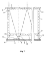
- Fig. 3
- ein Querschnitt durch eine schematische Teilansicht eines dritten Ausführungsbeispiels gemäß der Erfindung,
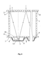
- Fig. 4
- ein Querschnitt durch eine schematische Teilansicht eines vierten Ausführungsbeispiels gemäß der Erfindung und
- Fig. 5
- ein Querschnitt durch eine schematische Teilansicht eines fünften Ausführungsbeispiels gemäß der Erfindung.
- Fig. 1
- a cross-section through a schematic partial view of a first embodiment according to the invention,
- Fig. 2
- a cross-section through a schematic partial view of a second embodiment according to the invention,
- Fig. 3
- a cross-section through a schematic partial view of a third embodiment according to the invention,
- Fig. 4
- a cross-sectional view through a schematic partial view of a fourth embodiment according to the invention and
- Fig. 5
- a cross-section through a schematic partial view of a fifth embodiment according to the invention.
Nach dem ersten Ausführungsbeispiel der Erfindung enthält das fotovoltaische Modul Seitenwände 1 aus Silikatglas, auf deren obere Kanten eine Fronttafel 2 aus Silikatglas mit Fresnel-Linsen 3 und auf deren untere Kanten eine Rücktafel 4 aus Silikatglas mit Solarzellen 5 und wärmeabführende Basen 6 befestigt sind. Die Fresnel-Linsen 3 sind aus Silikon hergestellt, weisen eine quadratische Form auf, sind dicht aneinander angeordnet und sind mit der Innenoberfläche des Glases, das eine Schutz- und Trägerfunktion erfüllt, fest verbunden. Jeder Fresnel-Linse 3 ist eine Solarzelle 5 zugeordnet, die auf einer wärmeabführenden Metallbasis 6 befestigt ist. Die wärmeabführenden Basen 6 werden auf der Frontseite des Glases der Rücktafel 4 so angeordnet, dass die lichtaufnehmende Oberfläche der Solarzelle 5 auf der optischen Linie der entsprechenden Fresnel-Linse 3 liegt. Zwischen der Rücktafel 4 und der Fronttafel 2 ist eine zusätzliche Zwischentafel 7 aus Silikatglas angeordnet, auf deren Oberfläche flachkonvexe Silikonlinsen 8 auf einer Achse mit den entsprechenden Fresnel-Linsen 3 und den Solarzellen 5 angebracht sind. Der Abstand von der Zwischentafel 7 bis zu den wärmeabführenden Basen 6 ist größer als die Stärke der Solarzellen 5, aber kleiner als die Größendifferenz der Brennweite der flachkonvexen Linsen 8 und die Stärke der Zwischentafel 7. Für jeden Einzelfall wird dieser Abstand durch die optischen Parameter zweier Sonnenstrahlungskonzentratoren, der Fresnel-Linsen 3 und der flachkonvexen Linsen 8, durch die Bedingungen der optimalen Fokussierung des optischen Systems bestimmt, dass die lichtaufnehmenden Oberflächen der Solarzellen 5 im Brennpunktfleck zweier Konzentratoren, der entsprechenden Fresnel-Linsen 3 und der flachkonvexen Linsen 8, liegen. Die flachkonvexen Linsen 8 werden als Kurzfokuslinsen ausgewählt; deswegen ist der Abstand von der Oberfläche der Zwischentafel 7 bis zur Frontoberfläche der Rücktafel 4 im Vergleich zum Abstand zwischen der Fronttafel 2 und der Zwischentafel 7 gering.According to the first embodiment of the invention, the photovoltaic module contains
In den gegenüberliegenden Seitenwänden 1 sind unmittelbar über der zusätzlichen Zwischentafel 7 und unter der Fronttafel 2 Durchlasshülsen 9 angeordnet, durch deren Öffnungen der innere Modulraum, der zwischen der Zwischentafel 7 und der Fronttafel 2 eingeschlossen ist, mit der Umwelt verbunden ist. Somit bleibt nur der Raum zwischen der Rücktafel 4 und der dieser nahe liegenden Zwischentafel 7 zum Schutz der Solarzellen 5 vor Umwelteinwirkungen dicht verschlossen. In diesem Raum ist eine kleine Luftmenge vorhanden, und Änderungen des Innendrucks bei Temperaturänderungen verursachen praktisch kein Entstehen von mechanischen Spannungen im Modulaufbau. Im Raum zwischen der Fronttafel 2 und der Zwischentafel 7 sind die Fresnel-Linsen 3 und die flachkonvexen Linsen 8, die aus Silikon hergestellt sind, angebracht, die ihre Eigenschaften unter der Einwirkung von Feuchtigkeit nicht ändern. Die Verbindung dieses Raumes mit der Umwelt schließt das Entstehen eines Druckgefälles zwischen dem Modulinneren und der Atmosphäre bei Temperaturänderungen vollständig aus. Durch eine derartige Lösung wird somit das Entstehen von mechanischen Spannungen im Modulaufbau im Gegensatz zum Prototyp ausgeschlossen, in dem bei intensiven Temperaturänderungen die mechanischen Spannungen ein kritisches Niveau erreichen können.In the
Die wärmeabführende Metallbasis 6 bildet auch einen der elektrischen Kontakte der Solarzelle. Der zweite Kontakt wird durch eine obere Metallschicht 10 gebildet, die ein Hartglasgewebe abdeckt, das auf der wärmeabführenden Basis 6 befestigt ist, der ein Drahtkontakt (auf den Figuren nicht gezeigt) zugeführt ist, der mit seinem anderen Ende am Kontaktnetz der Solarzelle 5 angeschlossen ist. Die Umschaltung der Solarzellen 5 wird durch Kontakte vorgenommen, die an der Metallbasis 6 und die obere Metallschicht 10 des Hartglasgewebes angeschlossen sind.The heat dissipating
Mit Hilfe der Glasseitenwände 1 des Moduls werden die Parallelität der Fronttafel 2, der Rücktafel 4 und der Zwischentafel 7 sowie deren gegenseitige Anordnung mit Rücksicht auf die Sicherung einer genauen Fokussierung des optischen Systems gewährleistet. Die Befestigung der Seitenwände 1 untereinander und an den Tafeln 2, 4 und 7 wird mittels eines Abdichtungsklebers 11 vorgenommen, wodurch ihre feste Verbindung untereinander und die Dichtheit des inneren Modulraums zwischen der Rücktafel 4 und der Zwischentafel 7 gegenüber der Atmosphäre sichergestellt wird, wobei der Schutz der Solarzellen 5 vor äußeren Faktoren gewährleistet wird.With the help of the
Im zweiten Ausführungsbeispiel der Erfindung (Fig. 2) enthält das fotovoltaische Modul Seitenwände 1 aus Silikatglas, auf deren obere Kanten eine Fronttafel 2 aus Silikatglas mit Fresnel-Linsen 3 und auf deren untere Kanten eine wärmeabführende Metallplatte 6 mit Solarzellen 5 befestigt sind. Somit bildet die Metallplatte 6 eine Rücktafel des fotovoltaischen Moduls.In the second exemplary embodiment of the invention (FIG. 2), the photovoltaic module contains
Die Fresnel-Linsen 3 sind aus Silikon hergestellt und mit der inneren Glasoberfläche der Fronttafel 2 fest verbunden. Jeder Fresnel-Linse 3 ist eine Solarzelle 5 zugeordnet, die auf der wärmeabführenden Metallplatte 6 befestigt ist. Die wärmeabführende Metallplatte 6 wird so angeordnet, dass die lichtaufnehmenden Oberflächen der Photozellen 5 auf den optischen Linien der entsprechenden Fresnel-Linsen 3 liegen.The
Zwischen der Metallplatte 6 und der Fronttafel 2 ist eine zusätzliche Zwischentafel 7 aus Silikatglas angeordnet, auf deren rückwärtigen Oberfläche flachkonvexe Linsen 8 aus Silikon auf einer Achse mit den entsprechenden Fresnel-Linsen 3 und der Solarzellen 5 angebracht sind. Der Abstand von der Zwischentafel 7 und der Oberfläche der wärmeabführenden Platte 6 ist größer als die Summe der Stärke der Solarzelle 5 und der flachkonvexen Linse 8, aber kleiner als ihre Brennweite.Between the
In den gegenüberliegenden Seitenwänden 1 sind direkt über der zusätzlichen Zwischentafel 7 und unter der Fronttafel 2 Durchlasshülsen 9 angeordnet, durch deren Öffnungen der Modulinnenraum zwischen der Zwischentafel 7 und der Fronttafel 2 mit der Umwelt verbunden ist. Somit bleibt nur der Raum zwischen den nahe liegenden, rückwärtigen Oberfläche der Zwischentafel 7 und oberen Oberfläche der wärmeabführenden Platte 6 zum Schutz der Solarzellen 5 vor Einwirkungen der Umwelt dicht. Die flachkonvexen Linsen 8 kommen wie auch im ersten Ausführungsbeispiel als Kurzfokuslinsen zum Einsatz; dadurch ist der Abstand zwischen der rückwärtigen Oberfläche der Zwischentafel 7 und der oberen Oberfläche der wärmeabführenden Metallplatte 6 im Vergleich zum Abstand zwischen der Fronttafel 2 und der Zwischentafel 7 gering. Die wärmeabführende Metallplatte 6 bildet wie im oben beschriebenen Ausführungsbeispiel einen der elektrischen Kontakte der Solarzelle. Der zweite Kontakt wird durch eine obere Metallschicht 10 eines kaschierten Hartglasgewebes gebildet, das auf der wärmeabführenden Metallplatte 6 befestigt ist, dem ein Drahtkontakt (auf den Figuren nicht gezeigt) zugeführt ist, dessen anderes Ende am Kontaktnetz der Solarzelle 5 angeschlossen ist. Die Umschaltung der Solarzellen 5 wird durch Kontakte vorgenommen, die an der Metallplatte 6 und an der oberen Metallschicht 10 des Hartglasgewebes befestigt sind.In the
Die Befestigung der Seitenwände 1 und der Tafeln 2, 4 und 7 untereinander wird in diesem Ausführungsbeispiel des Moduls wie im ersten Ausführungsbeispiel mittels eines Abdichtungsklebers 11 vorgenommen.The attachment of the
Auf die rückwärtige Seite der wärmeabführenden Metallplatte 6 ist eine strom- und feuchtigkeitsisolierende Schutzschicht 12 aufgetragen. Diese Ausführung des Moduls verfügt im Vergleich zum Prototyp über dieselben Vorteile wie im oben beschriebenen Ausführungsbeispiel. Außerdem sichert diese Ausführungsart eine wirksamere Ableitung der Wärme von den Solarzellen 5 durch die Metallplatte in die Umwelt im Unterschied zum ersten Ausführungsbeispiel, in dem die Ableitung der Wärme durch die Glasplatte der Rücktafel verwirklicht wird.On the rear side of the heat-dissipating
Im dritten Ausführungsbeispiel der Erfindung (Fig. 3) enthält der fotovoltaische Modul Seitenwände 1 aus Silikatglas, auf deren obere Kanten eine Fronttafel 2 aus Silikatglas mit Fresnel-Linsen 3 und auf deren untere Kanten eine wärmeabführende Metallplatte 6 mit Solarzellen 5 befestigt sind. Somit bildet die Metallplatte 6 eine Rücktafel des fotovoltaischen Moduls.In the third exemplary embodiment of the invention (FIG. 3), the photovoltaic module contains
Die Fresnel-Linsen 3 sind aus Silikon hergestellt und mit der Innenglasoberfläche der Fronttafel 2 fest verbunden. Jeder Fresnel-Linse 3 entspricht eine eigene Solarzelle 5, die auf einer Metallplatte 6 befestigt ist. Die Metallplatte 6 wird so angeordnet, dass die Mitte der lichtaufnehmenden Oberflächen der Solarzellen 5 auf den optischen Achsen der entsprechenden Fresnel-Linsen 3 liegt.The
Zwischen der wärmeabführenden Metallplatte 6 und der Fronttafel 2 ist eine zusätzliche Zwischentafel 7 aus Silikatglas angeordnet, auf deren Frontoberfläche flachkonvexe Linsen 8 aus Silikon auf einer Achse mit den entsprechenden Fresnel-Linsen 3 und der Solarzellen 5 angeordnet sind. Der Abstand von der Zwischentafel 7 bis zu den wärmeabführenden Metallplatten 6 ist größer als die Stärke der Solarzellen 5 und kleiner als die Größendifferenz des Fokusabstands der flachkonvexen Linsen 8 und der Stärke der Zwischentafel 7.Between the heat-dissipating
In den gegenüberliegenden Seitenwänden 1 sind direkt über der zusätzlichen Zwischentafel 7 und unter der Fronttafel 2 Durchlasshülsen 9 angeordnet, durch deren Öffnungen der Modulinnenraum zwischen der Zwischentafel 7 und der Fronttafel 2 mit der Umwelt verbunden ist. Zum Schutz der Solarzellen 5 vor Umwelteinflüssen bleibt somit, wie in den oben beschriebenen Beispielen, nur der Raum zwischen der Rücktafel 4 und der dieser nahe liegenden Zwischentafel 7 dicht. Somit ist das zweite Beispiel des Moduls hinsichtlich dieses Teils der Konstruktion mit den oben beschriebenen Ausführungsbeispielen absolut identisch.In the
Die wärmeabführende Metallplatte 6 bildet wie im oben beschriebenen Ausführungsbeispiel einen elektrischen Kontakt der Solarzelle. Der zweite Kontakt wird durch eine obere Metallschicht 10 eines kaschierten Hartglasgewebes gebildet, die auf der wärmeabführenden Metallplatte 6 befestigt ist, der ein Drahtkontakt (in der Fig. 3 nicht gezeigt) zugeführt ist, dessen anderes Ende an das Kontaktnetz der Solarzelle 5 angeschlossen ist. Die Umschaltung der Solarzellen 5 wird durch Kontakte vorgenommen, die an der Metallplatte 6 und der oberen Metallschicht 10 des Hartglasgewebes befestigt sind. Auf die rückwärtige Seite der wärmeabführenden Metallplatte 6 ist eine strom- und feuchtigkeitsisolierende Schicht 12 aufgetragen. Das vorliegende Ausführungsbeispiel des Moduls verfügt im Vergleich zum Prototyp über dieselben Vorteile wie das zweite oben beschriebene Ausführungsbeispiel. Außerdem wird im Vergleich zum zweiten Ausführungsbeispiel durch die Anordnung der flachkonvexen Linsen 8 auf der Frontseite der Zwischentafel 7 der Abstand zwischen dieser Tafel und der wärmeabführenden Metallplatte 6 bei denselben optischen Parametern des zusätzlichen Konzentrators (der flachkonvexen Linse 8) kleiner. Dadurch wird die Kompaktheit des Moduls erhöht und das Volumen des dichten Raums zwischen der wärmeabführenden Metallplatte 6 und der rückwärtigen Oberfläche der Zwischentafel 7 verringert, wodurch mechanische Spannungen bei Änderungen der Umwelttemperatur zusätzlich vermindert werden.The heat dissipating
Im vierten Ausführungsbeispiel der Erfindung (Fig. 4) enthält das fotovoltaische Modul Seitenwände 1 aus Silikatglas, auf deren obere Kanten eine Fronttafel 2 aus Silikatglas mit Fresnel-Linsen 3 und auf deren untere Kanten eine Zwischentafel 7 aus Silikatglas befestigt sind. Unter deren rückwärtigen Oberfläche sind wärmeabführende Basen 6 als Schalen mit einem flachen Boden angebracht. Auf den zentralen, längslaufenden Linien der Schalen sind Solarzellen 5 gleichmäßig befestigt. Die Schalen sind mit ihren Abbiegekanten mit Hilfe beliebiger, bekannter Mittel an die rückwärtige Glasoberfläche der Zwischentafel 7 dicht befestigt, wobei die Schalen eine rückwärtige Tafel 4 bilden. Auf der rückwärtigen Oberfläche der Zwischentafel 7 sind flachkonvexe Silikon-Linsen 8 auf einer Achse mit den entsprechenden Fresnel-Linsen 3 angebracht. Der Abstand von der Zwischentafel 7 bis zu den Oberflächen der Flachböden der Schalen ist größer als die Summe der Stärken der Solarzelle und der flachkonvexen Linse und kleiner als deren Brennweite.In the fourth embodiment of the invention (FIG. 4), the photovoltaic module includes
In den gegenüberliegenden Seitenwänden 1 sind wie in allen oben beschriebenen Ausführungsbeispielen direkt über der zusätzlichen Zwischentafel 7 und unter der Fronttafel 2 Durchlasshülsen 9 angebracht, durch deren Öffnungen der Modulinnenraum zwischen der Zwischentafel 7 und der Fronttafel 2 mit der Umwelt verbunden ist. In diesem Ausführungsbeispiel bleibt somit nur das summarische Volumen, das durch die Räume zwischen der rückwärtigen Oberfläche der Zwischentafel 7 und der Innenoberfläche der Schalen ausgebildet wird, zur Schutzsicherung der Solarzellen 5 vor Außeneinwirkungen dicht.In the
Die wärmeabführenden Metallbasen (Schalen 6) bilden wie in allen oben beschriebenen Ausführungsbeispielen einen der elektrischen Kontakte der Solarzelle. Der zweite Kontakt wird durch eine obere Metallschicht 10 eines kaschierten Hartglasgewebes auf der wärmeabführenden Basis 6 gebildet, dem ein Bandkontakt (auf Fig. 4 nicht gezeigt) zugeführt ist, dessen anderes Ende an das Kontaktnetz der Solarzelle 5 angeschlossen ist. In diesem Ausführungsbeispiel werden diese Kontakte für alle Solarzellen in einer Schale zusammengeführt, d.h., dass die Solarzellen 5 parallel angeschlossen werden. Die Umschaltung zwischen den wämeabführenden Basen (Schalen 6) wird durch Metallkontakte (in Fig. 4 nicht gezeigt) vorgenommen, von denen ein Paar an jeder Basis 6 angeschlossen ist.The heat dissipating metal bases (shells 6) form, as in all embodiments described above, one of the electrical contacts of the solar cell. The second contact is formed by an
Die Befestigung der Seitenwände 1 und der Tafeln 2, 4 und 7 untereinander wird in diesem Ausführungsbeispiel wie in allen oben beschriebenen Beispielen vorgenommen. Auf die rückwärtige Seite der Metallschalen wird eine strom- und feuchtigkeitsisolierende Schutzschicht 12 aufgetragen.The attachment of the
Die vorliegende Modulausführung verfügt im Vergleich zum Prototyp über dieselben Vorteile wie die oben beschriebenen Ausführungsbeispiele. Außerdem ergibt sich in diesem Ausführungsbeispiel ein zusätzlicher Vorteil, der damit verbunden ist, dass der Einsatz von wärmeabführenden Basen (Schalen 6) mit der Gruppe geschalteter Solarzellen ermöglicht, die Montage der fotovoltaischen Module zu vereinfachen und bei ihrer Produktion automatisierte, verfahrenstechnische Prozesse einzusetzen, die in der Optoelektronik breit verwendet werden.The present module design has the same advantages over the prototype as the embodiments described above. In addition, in this embodiment, an additional advantage associated with the fact that the use of heat-dissipating bases (shells 6) with the group of connected solar cells allows to simplify the assembly of the photovoltaic modules and to use in their production automated, process engineering processes be widely used in optoelectronics.
Im fünften Ausführungsbeispiel der Erfindung (Fig. 5) enthält das fotovoltaische Modul Seitenwände 1 aus Silikatglas, auf deren obere Kanten eine Fronttafel 2 aus Silikatglas mit Fresnel-Linsen 3 und auf deren untere Kanten eine Zwischentafel 7 aus Silikatglas befestigt ist. Unter ihrer rückwärtigen Oberfläche sind die wärmeabführenden Basen 6 als Schalen mit einem Flachboden angebracht. Auf den zentralen, längslaufenden Linien der Schalen sind Solarzellen 5 gleichmäßig befestigt. Die Schalen werden durch ihre Abbiegekanten mit Hilfe beliebiger, bekannter Mittel an die rückwärtige Oberfläche der Zwischentafel 7 aus Glas dicht befestigt, wobei sie eine Rücktafel 4 bilden. Auf der Frontoberfläche der Zwischentafel 7 sind flachkonvexe Silikon-Linsen 8 auf einer Achse mit den entsprechenden Fresnel-Linsen 3 angeordnet. Der Abstand von der Zwischentafel 7 bis zu den wärmeabführenden Basen 6 ist größer als die Stärke der Solarzelle 5 und kleiner als die Größendifferenz der Brennweite der flachkonvexen Linsen 8 und der Stärke der Zwischentafel 7.In the fifth embodiment of the invention (FIG. 5), the photovoltaic module contains
In den gegenüberliegenden Seitenwänden 1 sind wie in allen oben beschriebenen Ausführungsbeispielen direkt über der zusätzlichen Zwischentafel 7 und unter der Fronttafel 2 Durchlasshülsen 9 angeordnet, durch deren Öffnungen der Innenraum zwischen der Zwischentafel 7 und der Fronttafel 2 mit der Umwelt verbunden ist.In the
Die elektrische Verbindung zwischen den Solarzellen 5 und die Umschaltung der wärmeabführenden Basen (Schalen 6) in diesem Ausführungsbeispiel werden wie im vierten Beispiel vorgenommen.The electrical connection between the
Die Befestigung der Wände und der Tafeln des Moduls untereinander in diesem Beispiel wird wie in allen oben beschriebenen Ausführungsbeispielen vorgenommen.The fastening of the walls and the panels of the module with each other in this example is carried out as in all the embodiments described above.
Auf die rückwärtige Seite der Metallschalen ist eine strom- und feuchtigkeitsisolierende Schicht 12 aufgetragen.On the rear side of the metal shells, a current and
Dieses Ausführungsbeispiel des Moduls verfügt im Vergleich zum Prototyp über dieselben Vorteile wie die oben beschriebenen Beispiele. In diesem Beispiel verringert sich im Vergleich zu dem vierten Ausführungsbeispiel zusätzlich das summarische Volumen, das durch die Räume zwischen der rückwärtigen Oberfläche der Zwischentafel 7 und durch die innere Oberfläche der Schalen gebildet wird, infolge der Anordnung der flachkonvexen Linsen 8 auf der Frontoberfläche der Zwischentafel 7.This embodiment of the module has the same advantages over the prototype as the examples described above. In addition, in this example, as compared with the fourth embodiment, the cumulative volume formed by the spaces between the rear surface of the
Der Betrieb der Ausführungsbeispiele der vorliegenden Erfindung wird am Betrieb des ersten Ausführungsbeispiels beispielhaft betrachtet.The operation of the embodiments of the present invention will be exemplified in the operation of the first embodiment.
Beim Modulbetrieb konzentrieren die senkrecht zu den Sonnenstrahlen ausgerichteten Fresnel-Linsen 3 die Sonnenstrahlen und bündeln diese auf die lichtaufnehmenden Oberflächen der Solarzellen 5. Die Solarzellen 5 wandeln die Quantenenergie des Lichts in elektrische Energie um, wobei eine Potentialdifferenz zwischen den Kontakten erzeugt wird. Die vom Modul produzierte Elektroenergie wird einem äußeren Nutzer oder einem Energiespeicher zugeführt. Die von den Solarzellen 5 abgeführte Wärme wird in den wärmeabführenden Metallbasen 6 verteilt, dem Glas der Rücktafel 4 zugeführt und dann in die Umwelt abgegeben.In module operation, the
Die übrigen Ausführungsbeispiele der fotovoltaischen Module funktionieren identisch zum ersten Beispiel. Der Unterschied besteht nur darin, dass die Wärme von den wärmeabführenden Basen (im zweiten und dritten Ausführungsbeispiel sind dies Metallplatten, im vierten und fünften Ausführungsbeispiel sind dies Schalen) in die Umwelt abgegeben wird.The other embodiments of the photovoltaic modules function identically to the first example. The only difference is that the heat from the heat dissipating bases (in the second and third embodiments, these are metal plates, in the fourth and fifth embodiments, these are shells) is released into the environment.
Aus den beschriebenen Ausführungsbeispielen der Erfindung ist für jeden Fachmann in diesem Bereich die Möglichkeit der Realisierung unter der gleichzeitigen Lösung der gestellten Aufgabe ganz offensichtlich. Dabei ist es ebenso offensichtlich, dass bei der Realisierung der Ausführungsbeispiele der Erfindung unbedeutende Veränderungen in der Konstruktion vorgenommen werden können, die jedoch die Grenzen der unten angeführten Ansprüche der Erfindung nicht überschreiten.From the described embodiments of the invention, the possibility of realization under the simultaneous solution of the problem is quite obvious to any expert in this field. It is also obvious that in the implementation of the embodiments of the invention insignificant changes in the construction can be made, but do not exceed the limits of the claims below of the invention.
Die Ausführungen von fotovoltaischen Modulen gemäß der vorliegenden Erfindung sind in ihrer Konstruktion einfach. Sie verfügen über hohe Festigkeitsdaten, die einen sicheren und langfristigen Betrieb gewährleisten, sind bei der Herstellung technisch hoch gerecht und verfügen über eine große Energieproduktivität und hohe technischwirtschaftliche Parameter.The embodiments of photovoltaic modules according to the present invention are simple in their construction. They have high strength data, which ensure safe and long-term operation, are technically high in production and have high energy productivity and high technical-economic parameters.
Claims (10)
dadurch gekennzeichnet,
dass zwischen den genannten Tafeln (2, 4) eine zusätzliche Zwischentafel (7) aus Silikatglas angeordnet ist, auf deren Frontseite flachkonvexe Linsen (8) auf einer Achse mit den entsprechenden Fresnel-Linsen (3) angeordnet sind, wobei der Abstand zwischen der Zwischentafel (7) und den wärmeabführenden Basen (6) größer als die Stärke der Solarzelle (5), aber kleiner als die Größendifferenz der Brennweite der flachkonvexen Linsen (8) und der Stärke der Zwischentafel (7) ist.Photovoltaic module with side walls (1), a front panel (2) made of silicate glass with Fresnel lenses (3) on its rear side and with a back panel (4) made of silicate glass with solar cells (5) and heat dissipating bases (6) on their front side,
characterized,
in that an additional intermediate panel (7) made of silicate glass is arranged between said panels (2, 4), on the front side of which flat convex lenses (8) are arranged on an axis with the corresponding Fresnel lenses (3), the distance between the intermediate panel (7) and the heat dissipating bases (6) is larger than the thickness of the solar cell (5) but smaller than the size difference of the focal length of the flat convex lenses (8) and the thickness of the intermediate board (7).
dadurch gekennzeichnet,
dass in seinen gegenüber liegenden Wänden (1) direkt über der zusätzlichen Zwischentafel und unter der Fronttafel (7 und 2) die Öffnungen (9) zur Kommunikation des inneren Raumes des Moduls zwischen diesen Paneelen mit der Umwelt ausgeführt werden.Photovoltaic module according to claim 1,
characterized,
in that, in its opposite walls (1), directly above the additional intermediate panel and below the front panel (7 and 2), are the openings (9) for communicating the interior space of the module between these panels with the environment.
dadurch gekennzeichnet,
dass das wärmeabführende Mittel als Metallplatte (6) ausgeführt ist und eine Rücktafel (4) bildet, zwischen der und der Fronttafel (2) zusätzlich eine Zwischentafel (7) aus Silikatglas angeordnet ist, auf deren rückwärtigen Seite flachkonvexe Linsen (8) auf einer Achse mit den entsprechenden Fresnel-Linsen (3) angebracht sind, wobei der Abstand zwischen der Zwischentafel (7) und der Oberfläche der wärmeabführenden Metallplatte (6) größer als die Summe der Stärken der Solarzelle (5) und der flachkonvexen Linse (8) und kleiner als deren Brennweite ist.Photovoltaic module with side walls (1), a front panel (2) made of silicate glass with Fresnel lenses (3) on its rear side and with a back panel (4) with solar cells (5) and a heat dissipating agent on the front side,
characterized,
in that the heat-dissipating means is designed as a metal plate (6) and forms a rear panel (4) between which and the front panel (2) additionally a silicate glass intermediate panel (7) is arranged, on its rear side flat-convex lenses (8) on one axis with the corresponding Fresnel lenses (3) are mounted, wherein the distance between the intermediate board (7) and the surface of the heat dissipating metal plate (6) greater than the sum of the strengths of the solar cell (5) and the flat convex lens (8) and smaller as their focal length is.
dadurch gekennzeichnet,
dass in seinen gegenüberliegenden Wänden (1) direkt über der zusätzlichen Zwischentafel und unter der Fronttafel (7 und 20) die Öffnungen (9) für die Kommunikation mit der Umwelt des inneren Raumes des Moduls zwischen diesen Tafeln ausgeführt sind.Photovoltaic module according to claim 3,
characterized,
in that its opposite walls (1) directly via the additional intermediate panel and the front panel (7 and 20), the openings (9) for communication with the environment of the inner space of the module between these panels are executed.
dadurch gekennzeichnet,
dass das Wärme abführende Mittel als eine Metallplatte (6) ausgeführt ist und eine Rücktafel ausbildet, zwischen der und der Fronttafel (2) eine zusätzliche Zwischentafel (7) aus Silikatglas angeordnet ist, auf deren Frontseite die flachkonvexen Linsen (8) auf einer Achse mit den entsprechenden Fresnel-Linsen (3) angebracht werden, wobei der Abstand zwischen der Zwischentafel (7) und der Oberfläche der Wärme abführenden Platte (6) größer als die Dicke der Solarzelle (5) und kleiner als die Größendifferenz der Brennweite der flachkonvexen Linsen (8) und die Dicke der Zwischentafel (7) ist.Photovoltaic module with side walls (1), a front panel (2) made of silicate glass with Fresnel lenses (3) on its rear side and with a back panel (4) with solar cells (5) and heat dissipating bases (6) on their front side,
characterized,
in that the heat-dissipating means is designed as a metal plate (6) and forms a back plate, between which and the front panel (2) an additional intermediate panel (7) made of silicate glass is arranged, on whose front side the flat-convex lenses (8) on an axis the distance between the intermediate board (7) and the surface of the heat dissipating plate (6) is greater than the thickness of the solar cell (5) and smaller than the size difference of the focal length of the flat convex lenses ( 8) and the thickness of the intermediate board (7).
dadurch gekennzeichnet,
dass in seinen gegenüberliegenden Seitenwänden (1) direkt über der zusätzlichen Zwischentafel (7) und unter der Fronttafel (2) Öffnungen (9) für die Verbindung mit der Umwelt des inneren Modulraums zwischen diesen Tafeln gebildet sind.Photovoltaic module according to one of claims 1 to 5,
characterized,
in that in its opposite side walls (1) directly above the additional intermediate panel (7) and below the front panel (2) there are formed openings (9) for connection with the environment of the inner modular space between these panels.
dadurch gekennzeichnet,
dass die Wärme abführenden Gründe (6) als Schalen mit Flachboden ausgeführt sind, durch deren zentrale längsläufigen Linien der Oberflächen die optischen Achsen der entsprechenden Fresnel-Linsen (3) laufen und eine Rücktafel ausbilden, zwischen dem und der Fronttafel (2) eine zusätzliche Zwischentafel (7) aus Silikatglas angeordnet ist, auf deren rückwärtigen Seite die flachkonvexen Linsen (8) auf einer Achse mit den entsprechenden Fresnel-Linsen (3) angebracht sind, wobei die Schalen durch ihre Oberteile mit der rückwärtigen Oberfläche der Zwischentafel (7) dicht verbunden sind und der Abstand zwischen der Zwischentafel (7) und den Oberflächen der flachen Schalenböden größer als die Dickensumme der Solarzelle (5) und der flachkonvexen Linse (8) und kleiner als deren Brennweite ist.Photovoltaic module, comprising the side walls, a front panel made of silicate glass with the Fresnel lenses on the rear side and a back panel with the solar cells and the heat dissipating reasons on the front side,
characterized,
that the heat dissipating reasons (6) are designed as shells with flat bottom through whose central longitudinal lines of the surfaces run the optical axes of the corresponding Fresnel lenses (3) and form a back panel, between the front panel and (2) an additional intermediate board (7) made of silicate glass, on the rear side of which the flat convex lenses (8) are mounted on an axis with the corresponding Fresnel lenses (3), the shells being tightly connected by their tops to the rear surface of the intermediate board (7) and the distance between the intermediate panel (7) and the surfaces of the flat tray bottoms is larger than the thickness of the solar cell (5) and the flat convex lens (8) and smaller than the focal length thereof.
dadurch gekennzeichnet,
dass in seinen gegenüber liegenden Wänden (1) direkt über der zusätzlichen Zwischentafel und unter der Fronttafeln (7 und 2) die Öffnungen (9) für die Kommunikation mit der Umwelt des inneren Raumes des Moduls zwischen diesen Tafeln ausgeführt sind.Photovoltaic module according to claim 7,
characterized,
that, in its opposite walls (1), the openings (9) are designed for communication with the environment of the inner space of the module between these panels directly above the additional intermediate plate and under the front panels (7 and 2).
dadurch gekennzeichnet,
dass die Wärme abführenden Gründe (6) als Schalen mit dem Flachboden ausgeführt sind, durch deren zentrale, längsläufigen Linien der Oberflächen die optischen Achsen der entsprechenden Fresnel-Linsen (3) laufen, und eine rückwärtige Tafel ausbilden, zwischen der und der Fronttafel (2) eine zusätzliche Zwischentafel (7) aus Silikatglas angeordnet ist, auf deren Frontseite die flachkonvexen Linsen (8) auf einer Achse mit den entsprechenden Fresnel-Linsen (3) angebracht werden, wobei die Schalen durch ihre Oberteile mit der rückwärtigen Oberfläche der Zwischentafel (7) dicht verbunden sind und der Abstand zwischen der Zwischentafel (7) und den Oberflächen der flachen Schalenböden größer als die Dicke der Solarzelle (5) und kleiner als die Grö-ßendifferenz der Brennweite der flachkonvexen Linsen (8) und Dicke der Zwischentafel (7) ist.Photovoltaic module comprising the side walls and a front panel of silicate glass with the Fresnel lenses on the rear side thereof and a back panel with the solar cells and the heat dissipating reasons on their Front page
characterized,
in that the heat-dissipating reasons (6) are designed as trays with the flat bottom, through whose central, longitudinal lines of the surfaces the optical axes of the corresponding Fresnel lenses (3) run, and form a rear panel between which and the front panel (2 ) an additional intermediate board (7) made of silicate glass is arranged, on the front side of which the flat convex lenses (8) are mounted on an axis with the corresponding Fresnel lenses (3), the shells being connected by their upper parts to the rear surface of the intermediate board (7 ) and the distance between the intermediate board (7) and the surfaces of the flat tray bottoms is greater than the thickness of the solar cell (5) and smaller than the size difference of the focal length of the flat convex lenses (8) and thickness of the intermediate board (7) is.
dadurch gekennzeichnet,
dass in seinen gegenüberliegenden Wänden (1) direkt über der zusätzlichen Zwischentafel und unter den Fronttafeln (7 und 2) die Öffnungen (9) für die Kommunikation mit der Umwelt des inneren Raumes des Moduls zwischen diesen Tafeln ausgeführt sind.Photovoltaic module according to claim 9,
characterized,
in that its opposite walls (1) directly via the additional intermediate plate and under the front panels (7 and 2), the openings (9) for communication with the environment of the inner space of the module between these panels are executed.
Applications Claiming Priority (2)
| Application Number | Priority Date | Filing Date | Title |
|---|---|---|---|
| PCT/RU2004/000429 WO2006049524A1 (en) | 2004-11-01 | 2004-11-01 | Photovoltaic module |
| RU2004131615/28A RU2307294C9 (en) | 2004-11-01 | 2004-11-01 | Photoelectric module (modifications) |
Publications (3)
| Publication Number | Publication Date |
|---|---|
| EP1835547A1 true EP1835547A1 (en) | 2007-09-19 |
| EP1835547A4 EP1835547A4 (en) | 2009-03-18 |
| EP1835547B1 EP1835547B1 (en) | 2011-08-24 |
Family
ID=36319440
Family Applications (1)
| Application Number | Title | Priority Date | Filing Date |
|---|---|---|---|
| EP04821428A Not-in-force EP1835547B1 (en) | 2004-11-01 | 2004-11-01 | Photovoltaic module |
Country Status (5)
| Country | Link |
|---|---|
| EP (1) | EP1835547B1 (en) |
| AT (1) | ATE521992T1 (en) |
| KZ (1) | KZ21493B (en) |
| RU (1) | RU2307294C9 (en) |
| WO (1) | WO2006049524A1 (en) |
Cited By (15)
| Publication number | Priority date | Publication date | Assignee | Title |
|---|---|---|---|---|
| WO2009100894A2 (en) * | 2008-02-13 | 2009-08-20 | Solartec Ag | Photovoltaic device, method for the production of a photovoltaic device, and solar system |
| WO2010012479A2 (en) * | 2008-07-30 | 2010-02-04 | Fraunhofer-Gesellschaft zur Förderung der angewandten Forschung e.V. | Photovoltaic device and method for producing a concentrator optical unit |
| WO2010137687A1 (en) * | 2009-05-28 | 2010-12-02 | 京セラ株式会社 | Component for photoelectric conversion device, photoelectric conversion device, and photoelectric conversion module |
| EP2286051A1 (en) * | 2008-04-02 | 2011-02-23 | Morgan Solar Inc. | Solar panel window |
| EP2323176A1 (en) * | 2009-11-16 | 2011-05-18 | 'Telecom-STV' Company Limited | Photoelectric concentrator module |
| WO2010091391A3 (en) * | 2009-02-09 | 2011-09-29 | Semprius, Inc. | Concentrator-type photovoltaic (cpv) modules, receivers and sub-receivers and methods of forming same |
| WO2011003903A3 (en) * | 2009-07-08 | 2011-11-10 | Agc Glass Europe | Concentrator photovoltaïc device with an improved efficiency |
| WO2011034640A3 (en) * | 2009-09-18 | 2011-11-17 | The Boeing Company | Enclosed, off-axis solar concentrator |
| WO2014037722A1 (en) * | 2012-09-05 | 2014-03-13 | Fullsun Photovoltaics Limited | Concentrated photovoltaic (cpv) cell module with secondary optical element and method of fabrication |
| EP2590231A3 (en) * | 2011-11-04 | 2014-05-07 | Most Energy Corporation | Condensing lens and photovoltaic system using the same |
| EP2139046A4 (en) * | 2007-04-16 | 2014-09-24 | Zakrytoe Aktsionernoe Obschestvo Technoexan | Photovoltaic module |
| US8940999B1 (en) | 2009-12-07 | 2015-01-27 | The Boeing Company | Modular off-axis solar concentrator |
| US9054251B1 (en) | 2011-07-28 | 2015-06-09 | The Boeing Company | Solar collector array |
| EP3236307A4 (en) * | 2014-12-19 | 2018-09-26 | Esteves Palmeira, André Luiz | Electromagnetic and solar energy concentrator |
| US10418501B2 (en) | 2015-10-02 | 2019-09-17 | X-Celeprint Limited | Wafer-integrated, ultra-low profile concentrated photovoltaics (CPV) for space applications |
Families Citing this family (12)
| Publication number | Priority date | Publication date | Assignee | Title |
|---|---|---|---|---|
| IL204034A (en) * | 2009-02-24 | 2015-05-31 | Schott Ag | Photovoltaic device with concentrator optics |
| RU2395136C1 (en) | 2009-06-15 | 2010-07-20 | Учреждение Российской академии наук Физико-технический институт им. А.Ф. Иоффе РАН | Photovoltaic module |
| RU2444808C2 (en) * | 2010-03-02 | 2012-03-10 | Российская академия сельскохозяйственных наук Государственное научное учреждение Всероссийский научно-исследовательский институт электрификации сельского хозяйства Российской академии сельскохозяйственных наук (ГНУ ВИЭСХ Россельхозакадемии) | Solar photovoltaic module with concentrator |
| RU2444809C2 (en) * | 2010-06-10 | 2012-03-10 | Российская академия сельскохозяйственных наук Государственное научное учреждение Всероссийский научно-исследовательский институт электрификации сельского хозяйства Российской академии сельскохозяйственных наук (ГНУ ВИЭСХ Россельхозакадемии) | Solar photovoltaic module with concentrator |
| US20120318323A1 (en) * | 2011-02-14 | 2012-12-20 | Paul Anthony Tomaso | Ground mount ballast solar racking system |
| RU2496181C1 (en) * | 2012-04-24 | 2013-10-20 | Федеральное государственное бюджетное учреждение науки Физико-технический институт им. А.Ф. Иоффе Российской академии наук | Photoelectric concentrator submodule |
| RU2578735C1 (en) * | 2014-12-10 | 2016-03-27 | Федеральное государственное бюджетное учреждение науки Физико-технический институт им. А.Ф. Иоффе Российской академии наук | Concentrator solar photovoltaic module |
| RU2611693C1 (en) * | 2015-11-13 | 2017-02-28 | Федеральное государственное бюджетное учреждение науки Физико-технический институт им. А.Ф. Иоффе Российской академии наук | Solar concentrator module |
| CN106094211A (en) * | 2016-08-03 | 2016-11-09 | 杭州照相机械研究所 | A kind of head-mounted display apparatus |
| RU2641627C1 (en) * | 2016-11-22 | 2018-01-18 | Федеральное государственное бюджетное учреждение науки Физико-технический институт им. А.Ф. Иоффе Российской академии наук | Solar photovoltaic concentrator module |
| JP6814890B2 (en) * | 2016-12-30 | 2021-01-20 | ボリーメディア ホールディングス カンパニー リミテッドBolymedia Holdings Co. Ltd. | Condensing solar energy device |
| RU2744355C1 (en) * | 2020-08-04 | 2021-03-05 | Федеральное государственное бюджетное учреждение науки Физико-технический институт им. А.Ф. Иоффе Российской академии наук | Concentrator photoelectric module |
Citations (8)
| Publication number | Priority date | Publication date | Assignee | Title |
|---|---|---|---|---|
| DE2924510A1 (en) * | 1979-06-18 | 1981-01-08 | Imchemie Kunststoff Gmbh | Solar cell concentrator with Fresnel lens - has single or double sided Fresnel lens embedded in plastics or glass |
| US4830678A (en) * | 1987-06-01 | 1989-05-16 | Todorof William J | Liquid-cooled sealed enclosure for concentrator solar cell and secondary lens |
| US5091018A (en) * | 1989-04-17 | 1992-02-25 | The Boeing Company | Tandem photovoltaic solar cell with III-V diffused junction booster cell |
| US5123968A (en) * | 1989-04-17 | 1992-06-23 | The Boeing Company | Tandem photovoltaic solar cell with III-V diffused junction booster cell |
| EP0560107A1 (en) * | 1992-03-13 | 1993-09-15 | Gerhard Feustle | Device for concentrating or deflecting light |
| JPH07260261A (en) * | 1994-03-22 | 1995-10-13 | Yazaki Corp | Solar water heater |
| US6384320B1 (en) * | 2000-10-13 | 2002-05-07 | Leon Lung-Chen Chen | Solar compound concentrator of electric power generation system for residential homes |
| US20030075212A1 (en) * | 2001-10-23 | 2003-04-24 | Chen Leon L.C. | Photovolataic array module design for solar electric power generation systems |
Family Cites Families (5)
| Publication number | Priority date | Publication date | Assignee | Title |
|---|---|---|---|---|
| US3985116A (en) * | 1974-04-22 | 1976-10-12 | Kaptron, Inc. | High efficiency solar panel |
| JPS5848477A (en) * | 1981-09-17 | 1983-03-22 | Nec Corp | Condenser type solar electric generator |
| US20040194820A1 (en) * | 2000-01-20 | 2004-10-07 | Steven Barone | Self tracking, wide angle solar concentrators |
| RU2194927C1 (en) * | 2001-04-16 | 2002-12-20 | Исаев Пайзулла Исаевич | Solar collector |
| US7388146B2 (en) * | 2002-04-24 | 2008-06-17 | Jx Crystals Inc. | Planar solar concentrator power module |
-
2004
- 2004-11-01 AT AT04821428T patent/ATE521992T1/en active
- 2004-11-01 EP EP04821428A patent/EP1835547B1/en not_active Not-in-force
- 2004-11-01 KZ KZ20072009A patent/KZ21493B/en unknown
- 2004-11-01 RU RU2004131615/28A patent/RU2307294C9/en not_active IP Right Cessation
- 2004-11-01 WO PCT/RU2004/000429 patent/WO2006049524A1/en active Application Filing
Patent Citations (8)
| Publication number | Priority date | Publication date | Assignee | Title |
|---|---|---|---|---|
| DE2924510A1 (en) * | 1979-06-18 | 1981-01-08 | Imchemie Kunststoff Gmbh | Solar cell concentrator with Fresnel lens - has single or double sided Fresnel lens embedded in plastics or glass |
| US4830678A (en) * | 1987-06-01 | 1989-05-16 | Todorof William J | Liquid-cooled sealed enclosure for concentrator solar cell and secondary lens |
| US5091018A (en) * | 1989-04-17 | 1992-02-25 | The Boeing Company | Tandem photovoltaic solar cell with III-V diffused junction booster cell |
| US5123968A (en) * | 1989-04-17 | 1992-06-23 | The Boeing Company | Tandem photovoltaic solar cell with III-V diffused junction booster cell |
| EP0560107A1 (en) * | 1992-03-13 | 1993-09-15 | Gerhard Feustle | Device for concentrating or deflecting light |
| JPH07260261A (en) * | 1994-03-22 | 1995-10-13 | Yazaki Corp | Solar water heater |
| US6384320B1 (en) * | 2000-10-13 | 2002-05-07 | Leon Lung-Chen Chen | Solar compound concentrator of electric power generation system for residential homes |
| US20030075212A1 (en) * | 2001-10-23 | 2003-04-24 | Chen Leon L.C. | Photovolataic array module design for solar electric power generation systems |
Non-Patent Citations (1)
| Title |
|---|
| See also references of WO2006049524A1 * |
Cited By (22)
| Publication number | Priority date | Publication date | Assignee | Title |
|---|---|---|---|---|
| EP2139046A4 (en) * | 2007-04-16 | 2014-09-24 | Zakrytoe Aktsionernoe Obschestvo Technoexan | Photovoltaic module |
| WO2009100894A2 (en) * | 2008-02-13 | 2009-08-20 | Solartec Ag | Photovoltaic device, method for the production of a photovoltaic device, and solar system |
| WO2009100894A3 (en) * | 2008-02-13 | 2010-04-15 | Solartec Ag | Photovoltaic device, method for the production of a photovoltaic device, and solar system |
| EP2286051A4 (en) * | 2008-04-02 | 2012-05-02 | Morgan Solar Inc | Solar panel window |
| EP2286051A1 (en) * | 2008-04-02 | 2011-02-23 | Morgan Solar Inc. | Solar panel window |
| WO2010012479A2 (en) * | 2008-07-30 | 2010-02-04 | Fraunhofer-Gesellschaft zur Förderung der angewandten Forschung e.V. | Photovoltaic device and method for producing a concentrator optical unit |
| US8969716B2 (en) | 2008-07-30 | 2015-03-03 | Fraunhofer-Gesellschaft Zur Foerderung Der Angewandten Forschung E.V. | Photovoltaic device and method for producing a concentrator lens system |
| WO2010012479A3 (en) * | 2008-07-30 | 2010-10-07 | Fraunhofer-Gesellschaft zur Förderung der angewandten Forschung e.V. | Photovoltaic device and method for producing a concentrator optical unit |
| US10416425B2 (en) | 2009-02-09 | 2019-09-17 | X-Celeprint Limited | Concentrator-type photovoltaic (CPV) modules, receiver and sub-receivers and methods of forming same |
| WO2010091391A3 (en) * | 2009-02-09 | 2011-09-29 | Semprius, Inc. | Concentrator-type photovoltaic (cpv) modules, receivers and sub-receivers and methods of forming same |
| US8592673B2 (en) | 2009-05-04 | 2013-11-26 | The Boeing Company | Enclosed, off-axis solar concentrator |
| WO2010137687A1 (en) * | 2009-05-28 | 2010-12-02 | 京セラ株式会社 | Component for photoelectric conversion device, photoelectric conversion device, and photoelectric conversion module |
| WO2011003903A3 (en) * | 2009-07-08 | 2011-11-10 | Agc Glass Europe | Concentrator photovoltaïc device with an improved efficiency |
| WO2011034640A3 (en) * | 2009-09-18 | 2011-11-17 | The Boeing Company | Enclosed, off-axis solar concentrator |
| EP2323176A1 (en) * | 2009-11-16 | 2011-05-18 | 'Telecom-STV' Company Limited | Photoelectric concentrator module |
| US8940999B1 (en) | 2009-12-07 | 2015-01-27 | The Boeing Company | Modular off-axis solar concentrator |
| US9660125B2 (en) | 2009-12-07 | 2017-05-23 | The Boeing Company | Method of making a modular off-axis solar concentrator |
| US9054251B1 (en) | 2011-07-28 | 2015-06-09 | The Boeing Company | Solar collector array |
| EP2590231A3 (en) * | 2011-11-04 | 2014-05-07 | Most Energy Corporation | Condensing lens and photovoltaic system using the same |
| WO2014037722A1 (en) * | 2012-09-05 | 2014-03-13 | Fullsun Photovoltaics Limited | Concentrated photovoltaic (cpv) cell module with secondary optical element and method of fabrication |
| EP3236307A4 (en) * | 2014-12-19 | 2018-09-26 | Esteves Palmeira, André Luiz | Electromagnetic and solar energy concentrator |
| US10418501B2 (en) | 2015-10-02 | 2019-09-17 | X-Celeprint Limited | Wafer-integrated, ultra-low profile concentrated photovoltaics (CPV) for space applications |
Also Published As
| Publication number | Publication date |
|---|---|
| WO2006049524A1 (en) | 2006-05-11 |
| RU2307294C9 (en) | 2007-12-27 |
| KZ21493B (en) | 2009-07-15 |
| ATE521992T1 (en) | 2011-09-15 |
| EP1835547A4 (en) | 2009-03-18 |
| RU2307294C2 (en) | 2007-09-27 |
| EP1835547B1 (en) | 2011-08-24 |
Similar Documents
| Publication | Publication Date | Title |
|---|---|---|
| EP1835547B1 (en) | Photovoltaic module | |
| DE60312358T2 (en) | Photovoltaic module with adjustable cooling body and method | |
| EP2139046A1 (en) | Photovoltaic module | |
| DE102007052338A1 (en) | Photovoltaic installation has multiple level mirrors for concentration of sunlight on concentrator module with photovoltaic element, where mirrors are aligned together in form of Fresnel mirror field in parallel manner | |
| DE202011104880U1 (en) | A solar cell receiver for use in a concentrated photovoltaic system using III-V semiconductor solar cells | |
| EP1891681A1 (en) | Concentrator photovoltaic device, pv concentrator module formed therefrom and production process therefor | |
| DE102005047132A1 (en) | Concentrator photovoltaic device; Photovoltaic device for use therein and manufacturing method therefor | |
| DE112006001229T5 (en) | Stationary photovoltaic module with low solar radiation concentration ratio | |
| EP1977453A2 (en) | Concentrator photovoltaics device with positioning aid | |
| DE102009004195A1 (en) | Solar module in an insulating glass composite and method of manufacture and application | |
| DE102010004008A1 (en) | Solar cell module and its surface layer | |
| EP1860706A1 (en) | FRP based thermo-photovoltaic element for wall and roof coverings | |
| DE102008035735A1 (en) | Open encapsulated concentrator system for solar radiation | |
| EP3231016A1 (en) | Photovoltaic module and photovoltaic system | |
| DE102011122281A1 (en) | Solar cell module and method for its production | |
| DE102022123915A1 (en) | Photovoltaic thermal module | |
| DE102004001248B3 (en) | Stationary photovoltaic solar energy concentrator has light reception surfaces of photovoltaic receivers positioned in focal planes of lens elements of non-imaging Fresnel lens | |
| EP2162684A2 (en) | Photovoltaic device with holographic structure for deflecting incident solar radiation, and method for producing it | |
| DE112017001985T5 (en) | PHOTOVOLTAIC SYSTEM WITH UNIFORM COOLED PHOTOVOLTAIC CELLS | |
| DE102009056779A1 (en) | Photovoltaic module | |
| WO2011110329A4 (en) | Photovoltaic element with optically functional conversion layer for improving the conversion of the incident light and method for producing said photovoltaic element | |
| DE102012024686A1 (en) | Partly transparent solar collector | |
| EP1677363A1 (en) | Solar cell module for roof mounting | |
| DE202013003101U1 (en) | photovoltaic device | |
| WO2007128305A1 (en) | Photovoltaic module with at least one crystalline solar cell |
Legal Events
| Date | Code | Title | Description |
|---|---|---|---|
| PUAI | Public reference made under article 153(3) epc to a published international application that has entered the european phase |
Free format text: ORIGINAL CODE: 0009012 |
|
| 17P | Request for examination filed |
Effective date: 20070601 |
|
| AK | Designated contracting states |
Kind code of ref document: A1 Designated state(s): AT BE BG CH CY CZ DE DK EE ES FI FR GB GR HU IE IS IT LI LU MC NL PL PT RO SE SI SK TR |
|
| RAP1 | Party data changed (applicant data changed or rights of an application transferred) |
Owner name: OOO,,RUSSKAJA SOLNENAJA KOMPANIJA'' |
|
| RIN1 | Information on inventor provided before grant (corrected) |
Inventor name: OOO,,RUSSKAJA SOLNENAJA KOMPANIJA'' |
|
| RIN1 | Information on inventor provided before grant (corrected) |
Inventor name: RUMANTSEV, VALERIY DMITRIEVICH Inventor name: CHALOV, ALESKSEY EVGENEVICH Inventor name: ZAZIMKO, VADIM NIKOLAEVICH Inventor name: SHAVARTS, MAKSIM SINOVEVICH Inventor name: IONOVA, EVGENIYA ALEKSANDROVNA Inventor name: ANDREEV, VYACHESLAV MIKHAYLOVICH Inventor name: ALFEROV, ZHORES IVANOVICH Inventor name: LOVYGIN, IGOR VLADIMIROVICH |
|
| DAX | Request for extension of the european patent (deleted) | ||
| RAP1 | Party data changed (applicant data changed or rights of an application transferred) |
Owner name: TECHNOEXAN LTD. |
|
| A4 | Supplementary search report drawn up and despatched |
Effective date: 20090218 |
|
| 17Q | First examination report despatched |
Effective date: 20090610 |
|
| GRAP | Despatch of communication of intention to grant a patent |
Free format text: ORIGINAL CODE: EPIDOSNIGR1 |
|
| GRAS | Grant fee paid |
Free format text: ORIGINAL CODE: EPIDOSNIGR3 |
|
| GRAA | (expected) grant |
Free format text: ORIGINAL CODE: 0009210 |
|
| AK | Designated contracting states |
Kind code of ref document: B1 Designated state(s): AT BE BG CH CY CZ DE DK EE ES FI FR GB GR HU IE IS IT LI LU MC NL PL PT RO SE SI SK TR |
|
| REG | Reference to a national code |
Ref country code: GB Ref legal event code: FG4D Free format text: NOT ENGLISH |
|
| REG | Reference to a national code |
Ref country code: CH Ref legal event code: EP |
|
| REG | Reference to a national code |
Ref country code: IE Ref legal event code: FG4D Free format text: LANGUAGE OF EP DOCUMENT: GERMAN |
|
| REG | Reference to a national code |
Ref country code: DE Ref legal event code: R082 Ref document number: 502004012827 Country of ref document: DE Representative=s name: JECK - FLECK - HERRMANN PATENTANWAELTE, DE Ref country code: DE Ref legal event code: R082 Ref document number: 502004012827 Country of ref document: DE Representative=s name: JECK - FLECK PATENTANWAELTE, DE |
|
| REG | Reference to a national code |
Ref country code: DE Ref legal event code: R096 Ref document number: 502004012827 Country of ref document: DE Effective date: 20111124 |
|
| REG | Reference to a national code |
Ref country code: NL Ref legal event code: VDEP Effective date: 20110824 |
|
| PG25 | Lapsed in a contracting state [announced via postgrant information from national office to epo] |
Ref country code: IS Free format text: LAPSE BECAUSE OF FAILURE TO SUBMIT A TRANSLATION OF THE DESCRIPTION OR TO PAY THE FEE WITHIN THE PRESCRIBED TIME-LIMIT Effective date: 20111224 Ref country code: SE Free format text: LAPSE BECAUSE OF FAILURE TO SUBMIT A TRANSLATION OF THE DESCRIPTION OR TO PAY THE FEE WITHIN THE PRESCRIBED TIME-LIMIT Effective date: 20110824 Ref country code: FI Free format text: LAPSE BECAUSE OF FAILURE TO SUBMIT A TRANSLATION OF THE DESCRIPTION OR TO PAY THE FEE WITHIN THE PRESCRIBED TIME-LIMIT Effective date: 20110824 Ref country code: PT Free format text: LAPSE BECAUSE OF FAILURE TO SUBMIT A TRANSLATION OF THE DESCRIPTION OR TO PAY THE FEE WITHIN THE PRESCRIBED TIME-LIMIT Effective date: 20111226 Ref country code: NL Free format text: LAPSE BECAUSE OF FAILURE TO SUBMIT A TRANSLATION OF THE DESCRIPTION OR TO PAY THE FEE WITHIN THE PRESCRIBED TIME-LIMIT Effective date: 20110824 |
|
| PG25 | Lapsed in a contracting state [announced via postgrant information from national office to epo] |
Ref country code: PL Free format text: LAPSE BECAUSE OF FAILURE TO SUBMIT A TRANSLATION OF THE DESCRIPTION OR TO PAY THE FEE WITHIN THE PRESCRIBED TIME-LIMIT Effective date: 20110824 Ref country code: CY Free format text: LAPSE BECAUSE OF FAILURE TO SUBMIT A TRANSLATION OF THE DESCRIPTION OR TO PAY THE FEE WITHIN THE PRESCRIBED TIME-LIMIT Effective date: 20110824 Ref country code: SI Free format text: LAPSE BECAUSE OF FAILURE TO SUBMIT A TRANSLATION OF THE DESCRIPTION OR TO PAY THE FEE WITHIN THE PRESCRIBED TIME-LIMIT Effective date: 20110824 Ref country code: GR Free format text: LAPSE BECAUSE OF FAILURE TO SUBMIT A TRANSLATION OF THE DESCRIPTION OR TO PAY THE FEE WITHIN THE PRESCRIBED TIME-LIMIT Effective date: 20111125 |
|
| REG | Reference to a national code |
Ref country code: IE Ref legal event code: FD4D |
|
| PG25 | Lapsed in a contracting state [announced via postgrant information from national office to epo] |
Ref country code: SK Free format text: LAPSE BECAUSE OF FAILURE TO SUBMIT A TRANSLATION OF THE DESCRIPTION OR TO PAY THE FEE WITHIN THE PRESCRIBED TIME-LIMIT Effective date: 20110824 Ref country code: IE Free format text: LAPSE BECAUSE OF FAILURE TO SUBMIT A TRANSLATION OF THE DESCRIPTION OR TO PAY THE FEE WITHIN THE PRESCRIBED TIME-LIMIT Effective date: 20110824 Ref country code: CZ Free format text: LAPSE BECAUSE OF FAILURE TO SUBMIT A TRANSLATION OF THE DESCRIPTION OR TO PAY THE FEE WITHIN THE PRESCRIBED TIME-LIMIT Effective date: 20110824 |
|
| BERE | Be: lapsed |
Owner name: TECHNOEXAN LTD. Effective date: 20111130 |
|
| PG25 | Lapsed in a contracting state [announced via postgrant information from national office to epo] |
Ref country code: IT Free format text: LAPSE BECAUSE OF FAILURE TO SUBMIT A TRANSLATION OF THE DESCRIPTION OR TO PAY THE FEE WITHIN THE PRESCRIBED TIME-LIMIT Effective date: 20110824 Ref country code: EE Free format text: LAPSE BECAUSE OF FAILURE TO SUBMIT A TRANSLATION OF THE DESCRIPTION OR TO PAY THE FEE WITHIN THE PRESCRIBED TIME-LIMIT Effective date: 20110824 Ref country code: RO Free format text: LAPSE BECAUSE OF FAILURE TO SUBMIT A TRANSLATION OF THE DESCRIPTION OR TO PAY THE FEE WITHIN THE PRESCRIBED TIME-LIMIT Effective date: 20110824 |
|
| PG25 | Lapsed in a contracting state [announced via postgrant information from national office to epo] |
Ref country code: DK Free format text: LAPSE BECAUSE OF FAILURE TO SUBMIT A TRANSLATION OF THE DESCRIPTION OR TO PAY THE FEE WITHIN THE PRESCRIBED TIME-LIMIT Effective date: 20110824 Ref country code: MC Free format text: LAPSE BECAUSE OF NON-PAYMENT OF DUE FEES Effective date: 20111130 |
|
| PLBE | No opposition filed within time limit |
Free format text: ORIGINAL CODE: 0009261 |
|
| REG | Reference to a national code |
Ref country code: CH Ref legal event code: PL |
|
| STAA | Information on the status of an ep patent application or granted ep patent |
Free format text: STATUS: NO OPPOSITION FILED WITHIN TIME LIMIT |
|
| GBPC | Gb: european patent ceased through non-payment of renewal fee |
Effective date: 20111124 |
|
| PG25 | Lapsed in a contracting state [announced via postgrant information from national office to epo] |
Ref country code: CH Free format text: LAPSE BECAUSE OF NON-PAYMENT OF DUE FEES Effective date: 20111130 Ref country code: LI Free format text: LAPSE BECAUSE OF NON-PAYMENT OF DUE FEES Effective date: 20111130 |
|
| 26N | No opposition filed |
Effective date: 20120525 |
|
| PG25 | Lapsed in a contracting state [announced via postgrant information from national office to epo] |
Ref country code: BE Free format text: LAPSE BECAUSE OF NON-PAYMENT OF DUE FEES Effective date: 20111130 |
|
| REG | Reference to a national code |
Ref country code: DE Ref legal event code: R097 Ref document number: 502004012827 Country of ref document: DE Effective date: 20120525 |
|
| PG25 | Lapsed in a contracting state [announced via postgrant information from national office to epo] |
Ref country code: GB Free format text: LAPSE BECAUSE OF NON-PAYMENT OF DUE FEES Effective date: 20111124 |
|
| REG | Reference to a national code |
Ref country code: AT Ref legal event code: MM01 Ref document number: 521992 Country of ref document: AT Kind code of ref document: T Effective date: 20111101 |
|
| PG25 | Lapsed in a contracting state [announced via postgrant information from national office to epo] |
Ref country code: AT Free format text: LAPSE BECAUSE OF NON-PAYMENT OF DUE FEES Effective date: 20111101 |
|
| PG25 | Lapsed in a contracting state [announced via postgrant information from national office to epo] |
Ref country code: ES Free format text: LAPSE BECAUSE OF FAILURE TO SUBMIT A TRANSLATION OF THE DESCRIPTION OR TO PAY THE FEE WITHIN THE PRESCRIBED TIME-LIMIT Effective date: 20111205 |
|
| PG25 | Lapsed in a contracting state [announced via postgrant information from national office to epo] |
Ref country code: LU Free format text: LAPSE BECAUSE OF NON-PAYMENT OF DUE FEES Effective date: 20111101 |
|
| PG25 | Lapsed in a contracting state [announced via postgrant information from national office to epo] |
Ref country code: BG Free format text: LAPSE BECAUSE OF FAILURE TO SUBMIT A TRANSLATION OF THE DESCRIPTION OR TO PAY THE FEE WITHIN THE PRESCRIBED TIME-LIMIT Effective date: 20111124 |
|
| PG25 | Lapsed in a contracting state [announced via postgrant information from national office to epo] |
Ref country code: TR Free format text: LAPSE BECAUSE OF FAILURE TO SUBMIT A TRANSLATION OF THE DESCRIPTION OR TO PAY THE FEE WITHIN THE PRESCRIBED TIME-LIMIT Effective date: 20110824 |
|
| PG25 | Lapsed in a contracting state [announced via postgrant information from national office to epo] |
Ref country code: HU Free format text: LAPSE BECAUSE OF FAILURE TO SUBMIT A TRANSLATION OF THE DESCRIPTION OR TO PAY THE FEE WITHIN THE PRESCRIBED TIME-LIMIT Effective date: 20110824 |
|
| REG | Reference to a national code |
Ref country code: FR Ref legal event code: PLFP Year of fee payment: 12 |
|
| PGFP | Annual fee paid to national office [announced via postgrant information from national office to epo] |
Ref country code: DE Payment date: 20151119 Year of fee payment: 12 |
|
| PGFP | Annual fee paid to national office [announced via postgrant information from national office to epo] |
Ref country code: FR Payment date: 20151119 Year of fee payment: 12 |
|
| REG | Reference to a national code |
Ref country code: DE Ref legal event code: R119 Ref document number: 502004012827 Country of ref document: DE |
|
| REG | Reference to a national code |
Ref country code: FR Ref legal event code: ST Effective date: 20170731 |
|
| PG25 | Lapsed in a contracting state [announced via postgrant information from national office to epo] |
Ref country code: FR Free format text: LAPSE BECAUSE OF NON-PAYMENT OF DUE FEES Effective date: 20161130 |
|
| PG25 | Lapsed in a contracting state [announced via postgrant information from national office to epo] |
Ref country code: DE Free format text: LAPSE BECAUSE OF NON-PAYMENT OF DUE FEES Effective date: 20170601 |