EP1835188A1 - High temperature superconducting magnetic bearing - Google Patents
High temperature superconducting magnetic bearing Download PDFInfo
- Publication number
- EP1835188A1 EP1835188A1 EP06300237A EP06300237A EP1835188A1 EP 1835188 A1 EP1835188 A1 EP 1835188A1 EP 06300237 A EP06300237 A EP 06300237A EP 06300237 A EP06300237 A EP 06300237A EP 1835188 A1 EP1835188 A1 EP 1835188A1
- Authority
- EP
- European Patent Office
- Prior art keywords
- segments
- magnetic bearing
- superconductor
- exciting system
- movable
- Prior art date
- Legal status (The legal status is an assumption and is not a legal conclusion. Google has not performed a legal analysis and makes no representation as to the accuracy of the status listed.)
- Granted
Links
- 230000005291 magnetic effect Effects 0.000 title claims abstract description 43
- 239000002887 superconductor Substances 0.000 claims abstract description 51
- 238000001816 cooling Methods 0.000 description 45
- 230000007246 mechanism Effects 0.000 description 9
- 239000000463 material Substances 0.000 description 8
- 125000006850 spacer group Chemical group 0.000 description 7
- 238000009413 insulation Methods 0.000 description 6
- 229910002480 Cu-O Inorganic materials 0.000 description 5
- 238000010276 construction Methods 0.000 description 4
- 239000010949 copper Substances 0.000 description 4
- 230000007547 defect Effects 0.000 description 4
- 230000004907 flux Effects 0.000 description 4
- 230000004913 activation Effects 0.000 description 3
- 230000008859 change Effects 0.000 description 3
- 239000004020 conductor Substances 0.000 description 3
- 229910052802 copper Inorganic materials 0.000 description 3
- 238000010586 diagram Methods 0.000 description 3
- 230000005294 ferromagnetic effect Effects 0.000 description 3
- 239000011810 insulating material Substances 0.000 description 3
- 239000000696 magnetic material Substances 0.000 description 3
- 230000008439 repair process Effects 0.000 description 3
- XEEYBQQBJWHFJM-UHFFFAOYSA-N Iron Chemical compound [Fe] XEEYBQQBJWHFJM-UHFFFAOYSA-N 0.000 description 2
- QJVKUMXDEUEQLH-UHFFFAOYSA-N [B].[Fe].[Nd] Chemical compound [B].[Fe].[Nd] QJVKUMXDEUEQLH-UHFFFAOYSA-N 0.000 description 2
- 229910052788 barium Inorganic materials 0.000 description 2
- 229910052797 bismuth Inorganic materials 0.000 description 2
- 229910052791 calcium Inorganic materials 0.000 description 2
- 239000000919 ceramic Substances 0.000 description 2
- 229910052745 lead Inorganic materials 0.000 description 2
- 238000000034 method Methods 0.000 description 2
- 229910001172 neodymium magnet Inorganic materials 0.000 description 2
- 238000007789 sealing Methods 0.000 description 2
- 230000006641 stabilisation Effects 0.000 description 2
- 229910052712 strontium Inorganic materials 0.000 description 2
- 239000000725 suspension Substances 0.000 description 2
- 229910052727 yttrium Inorganic materials 0.000 description 2
- OKTJSMMVPCPJKN-UHFFFAOYSA-N Carbon Chemical compound [C] OKTJSMMVPCPJKN-UHFFFAOYSA-N 0.000 description 1
- 229910000531 Co alloy Inorganic materials 0.000 description 1
- RYGMFSIKBFXOCR-UHFFFAOYSA-N Copper Chemical compound [Cu] RYGMFSIKBFXOCR-UHFFFAOYSA-N 0.000 description 1
- 229920002430 Fibre-reinforced plastic Polymers 0.000 description 1
- 229910052765 Lutetium Inorganic materials 0.000 description 1
- 229910052779 Neodymium Inorganic materials 0.000 description 1
- 229910000831 Steel Inorganic materials 0.000 description 1
- 229910052769 Ytterbium Inorganic materials 0.000 description 1
- 229910052799 carbon Inorganic materials 0.000 description 1
- 238000005266 casting Methods 0.000 description 1
- 238000009750 centrifugal casting Methods 0.000 description 1
- 239000012141 concentrate Substances 0.000 description 1
- 238000013016 damping Methods 0.000 description 1
- 238000006073 displacement reaction Methods 0.000 description 1
- 239000003302 ferromagnetic material Substances 0.000 description 1
- 239000011151 fibre-reinforced plastic Substances 0.000 description 1
- 239000003365 glass fiber Substances 0.000 description 1
- 239000012774 insulation material Substances 0.000 description 1
- 229910052742 iron Inorganic materials 0.000 description 1
- 229910052746 lanthanum Inorganic materials 0.000 description 1
- 230000007774 longterm Effects 0.000 description 1
- 230000013011 mating Effects 0.000 description 1
- 238000005259 measurement Methods 0.000 description 1
- 229910052761 rare earth metal Inorganic materials 0.000 description 1
- 238000005057 refrigeration Methods 0.000 description 1
- 230000003014 reinforcing effect Effects 0.000 description 1
- 229910052702 rhenium Inorganic materials 0.000 description 1
- 229910000938 samarium–cobalt magnet Inorganic materials 0.000 description 1
- 230000011218 segmentation Effects 0.000 description 1
- 230000000087 stabilizing effect Effects 0.000 description 1
- 239000010959 steel Substances 0.000 description 1
- 239000002937 thermal insulation foam Substances 0.000 description 1
- 230000007704 transition Effects 0.000 description 1
Images


Classifications
-
- F—MECHANICAL ENGINEERING; LIGHTING; HEATING; WEAPONS; BLASTING
- F16—ENGINEERING ELEMENTS AND UNITS; GENERAL MEASURES FOR PRODUCING AND MAINTAINING EFFECTIVE FUNCTIONING OF MACHINES OR INSTALLATIONS; THERMAL INSULATION IN GENERAL
- F16C—SHAFTS; FLEXIBLE SHAFTS; ELEMENTS OR CRANKSHAFT MECHANISMS; ROTARY BODIES OTHER THAN GEARING ELEMENTS; BEARINGS
- F16C32/00—Bearings not otherwise provided for
- F16C32/04—Bearings not otherwise provided for using magnetic or electric supporting means
- F16C32/0406—Magnetic bearings
- F16C32/0408—Passive magnetic bearings
- F16C32/0436—Passive magnetic bearings with a conductor on one part movable with respect to a magnetic field, e.g. a body of copper on one part and a permanent magnet on the other part
- F16C32/0438—Passive magnetic bearings with a conductor on one part movable with respect to a magnetic field, e.g. a body of copper on one part and a permanent magnet on the other part with a superconducting body, e.g. a body made of high temperature superconducting material such as YBaCuO
-
- F—MECHANICAL ENGINEERING; LIGHTING; HEATING; WEAPONS; BLASTING
- F16—ENGINEERING ELEMENTS AND UNITS; GENERAL MEASURES FOR PRODUCING AND MAINTAINING EFFECTIVE FUNCTIONING OF MACHINES OR INSTALLATIONS; THERMAL INSULATION IN GENERAL
- F16C—SHAFTS; FLEXIBLE SHAFTS; ELEMENTS OR CRANKSHAFT MECHANISMS; ROTARY BODIES OTHER THAN GEARING ELEMENTS; BEARINGS
- F16C2300/00—Application independent of particular apparatuses
- F16C2300/30—Application independent of particular apparatuses related to direction with respect to gravity
- F16C2300/32—Horizontal, e.g. bearings for supporting a horizontal shaft
Definitions
- the present invention is directed to a magnetic bearing comprising a rotating element, e.g. a shaft, within a stator element with a high temperature superconductor wherein the rotating element is held in a contactless state of suspension by magnetic forces.
- a high temperature superconductor is located in the field of a permanent magnet at a temperature above its transition temperature Tc, a magnetic flux will pass therethrough. If, in this case, the superconductor is cooled to a temperature below Tc then a portion of the magnetic flux will remain frozen into the superconducting material.
- shielding currents are induced in the superconductor by the permanent magnet which counteract the change of position. The resulting forces may be repulsive or attractive but are directed such that they counteract any deflection from the cooling position.
- Such bearings contain arrangements of permanent magnets as exciting system and a high temperature superconductor.
- the stator element with the superconductor surrounds essentially concentrically the rotor element with the exciting system upon cooling below Tc the magnetic force generated keep the rotor element at its position in free suspension.
- the actual position of the rotor element after cooling depends also on the own weight of the rotor element as well as the working load generally causing a deflection of the rotor element from the cooling position to the so called operation position.
- the strength of the magnetic forces acting between the superconductor and the exciting system should be desirably as high as possible.
- a magnetic bearing with a stator element comprising a cylindrical superconductor and a rotor element in the form of a shaft with permanent magnets as exciting system being mounted coaxially to the shaft and wherein the rotor element is arranged coaxially in relation to the stator element in operation position.
- the cylindrical superconductor is divided into at least 2 circle segment-shaped partial shells which can be displaced with respect to each other in radial direction by a suitable driving mechanism (actuator).
- actuator By movement of the partial shells the radial distance between the superconductor and the exciting system can be changed.
- the partial shells are moved away from each other so that the radial distance at the cooling position is larger than in the operation position.
- cooling of the superconductor below its Tc is necessary which, for example, for the well known YBa 2 Cu 3 O superconductor is 70K.
- the stator with the superconductor is housed in a tightly sealed cooling device, e.g a dewar, with very good heat insulation properties.
- a tightly sealed cooling device e.g a dewar
- vacuum tight cryogenic chambers are used wherein the stator element with the superconductor is housed in the vacuum sealed cooling jacket and the rotor element is positioned within the interior warm bore of the cryogenic device.
- the driving mechanism for moving the partial superconductor shells must be able to work with high reliability even at very low temperatures.
- the mechanism must be able to withstand the high temperature differences between the warm and the cold state.
- the material of which the driving mechanism is made must have high dimensional stability even when cooled to very low temperatures, that is, the thermal expansion coefficient must be suitably low. Due to this requirements a driving mechanism for operation at low temperatures is costly and restricted to specific materials only. Further, such movable mechanically stressed mechanisms is inherently prone to repair.
- a magnetic bearing with a fixed positioned stator element and a rotor element with at least one permanent magnet with annularly arrangement for exciting the superconductor of the stator wherein the annularly arranged permanent magnet is composed of at least two segments which are movable in relation to the superconductor of the stator.
- a magnetic bearing for contactless bearing of a rotor element within a stator element wherein the stator element comprises a superconductor and surrounds the rotor element, wherein the rotor element comprises a rotating element such as a shaft, wherein at least one permanent magnet is annularly arranged concentrically around the rotating element and wherein the at least one annularly arranged permanent magnet is composed of at least two segments which are movable in relation to the superconductor of the stator.
- the superconductor of the stator is fixedly positioned the stator element can be easily housed within an isolated cold chamber of a cryogenic device which is tightly sealed without the need of providing a driving mechanism which must withstand the temperature differences on cooling and without the need of mechanically stressed parts which are liable to repair, so that any untimely interruption of the operation of the magnetic bearing due to defects of the driving mechanism can be avoided.
- Figure 1 shows the general design of a magnetic bearing wherein the housing of the cooling device 16 is partially removed.
- the magnetic bearing has an overall cylindrical shape.
- the stator element 1 is composed of a cylindrically shaped superconductor 5 and a thermally conductive member 6 which is mounted on the outer surface of the superconductor 5.
- Supports 19 are provided for supporting the part with the superconductor 5 toward the interior of the wall of the cooling device.
- the rotor element 2 has a horizontal shaft 3 surrounded by an exciting system 10 with an arrangement of alternating permanent magnets 17 and flux collection poles 18.
- the stator element 1 is housed within the jacket of the cooling device 16 and the rotor element 2 within the interior warm bore of the cooling device 16 which is at room temperature.
- FeNdB iron-neodymium-boron
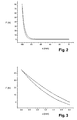
- the curve in figure 2 shows the course of the force on zero field cooling with the force increasing exponentially on approaching of the exciting systems, e. i. permanent magnet, to the superconductor.
- the upper curve reflects the course of the force on approaching and the lower curve on moving away. The difference is caused by the hysteresis of the magnets.
- Figures 4 and 5 show a cross section through an embodiment of an magnetic bearing according to the present invention in its operation position (figure 4) and in its cooling position (figure 5).
- FIG. 4 and 5 show a cross section through an embodiment of an magnetic bearing according to the present invention in its operation position (figure 4) and in its cooling position (figure 5).
- the magnetic bearing shown in figure 4 has in principle a hollow cylindrical overall shape and comprises a stator element 1 which coaxially surrounds a rotor element 2.
- the rotor element 2 comprises a rotating element 3 - here a shaft of a machine of non magnetic material - which is positioned within a also hollow cylindrical exciting system.
- the stator element 1 is composed of a cylindrically shaped superconductor 5.
- a thermally conductive member 6 is mounted, which is supported toward the wall of the cooling device by spacers 7 with free spaces 8 between the spacers 7.
- the thermally conductive member 6 serves to lead away heat from the superconductor 5 and, thus, is preferably made of a thermally highly conductive material such as copper.
- the stator element 1 is housed within the jacket of a cooling device such as a dewar, the wall thereof being indicated by the black line surrounding the stator element 1 along its outer and inner circumference.
- a layer 9 of thermally insulating material can be provided for shielding the warm interior of the cooling device from the cooled jacket with the stator element 1.
- Suitable insulating materials are generally known in the art.
- Cooling of the stator element 1 can be conducted by a suitable refrigerating machine.
- the refrigerating machine can be connected with the thermally conductive member 6 for indirect cooling of the superconductors.
- the refrigeration machine is not shown but is as such known.
- cryogenic coolers can be used.
- the outer surface of the member 6 can be covered with a further layer of insulating material (not shown).
- the superconductor 5 can be composed of any high temperature superconductor material known to be suitable for bearing applications.
- An example of one class of suited superconductor material are the ceramic oxide high temperature superconductors.
- Typical examples comprise ceramic oxide superconductors based on Y-Ae-Cu-O, (Y, Re)-Ae-Cu-O, Bi-Ae-Cu-O, (Bi, Pb)-Ae-Cu-O and (TI, Pb)-(Ae, Y)-Cu-O.
- Ae means at least one alkaline earth element, particularly, Ba, Ca and Sr.
- Re means at least one rare earth element, in particular, La, Lu, Sc, Sm, Nd or Yb.
- Especially suitable superconductors are those known by the reference YBCO-123 and YBCO-211, wherein the numerical combinations 123 and 211 stand for the stoichiometric ratios of the elements Y, Ba and Cu.
- the numerical combinations 2212 and 2223 stand for the stoichiometric ratios of the elements Bi, Sr, Ca and Cu, in particular those, wherein part of Bi is substituted by Pb.
- superconductors produced using a molten casting method in particular, a centrifugal casting method as disclosed, for example, in DE-A-3 830 092 , EP-A-0 451 532 , EP-A-0 462 409 and EP-A-0 477 493 , to which reference is expressly made.
- the cylindrically shaped superconductor 5 can be made of a single piece or can be composed of a plurality of segments attached together to form the circular body.
- the segments preferably have a trapezoidal shape.
- each segment has the same dimensions.
- the spacers 7 serve to stabilize the stator arrangement within the jacket of cooling device in a fixed position.
- the number and shape of the spacers 7 is not particularly critical as long as a stable fixed position of the stator arrangement is achieved.
- the spacers 7 should be composed of poorly thermally conductive material such as CFRP (carbon fibre reinforced plastic) for avoiding heat introduction.
- CFRP carbon fibre reinforced plastic
- the free space 8 between the spacers 7 is preferably evacuated. Further it is also possible to fill the free space 8 at least partially with at least one insulation means Any insulation means known can be applied suitable for this purpose.
- suitable insulation materials are insulation foam, super insulation, insulating flakes or glass fibres.
- the design and materials for exciting systems 10 for cylindrical magnetic bearings and as suitable for the present invention are generally known.
- the exciting system 10 can comprise a plurality of permanent magnets which are separated from each other by elements made of ferromagnetic material such as iron.
- Suitable permanent magnetic materials are for example neodymium-iron-boron (NdFeB) or samarium-cobalt-alloy (SmCo).
- the permanent magnets as well as the intermediate elements can have the shape of annular discs and are arranged one behind the other on a cylindrical support body 11 surrounding the shaft 3.
- the cylindrical support body 11 is preferably made of a non magnetic material such as steel.
- the first and last member of the stack composed of permanent magnets and intermediate members is an intermediate member.
- the arrangement of exciting system 10 and support body 11 is divided into segments which can be moved in relation to each other in radial direction.
- the segments can have a mirror-image symmetry. That is, as shown in figure 5 each segment is opposed by a mirror-imaged counterpart.
- the exciting system can be divided into three magnets, which can have same or different size.
- the operation position of the shaft depends not only on the magnetic forces but also on the own weight of the shaft and the working load.
- the radial distances of the segments can be selected accordingly. That is, different radial distances can be selected for the segments in the cooling position.
- the number, size and shape of the segments are selected according to need in consideration of the overall construction of the respective magnetic bearing. For example, it should be taken into account that the distance between the superconductor and the exciting system should be as long as possible in the cooling position and that an optimal stiffness is obtained.
- the bearing gap 4 should be as small as possible.
- one or more of the segments can be stationary positioned with one or more others being movable.
- the specific design of the exciting system can vary depending on the demands of the concrete application and in view of the desired bearing force and stiffness of the system.
- the exciting system can be connected to a commen actuator
- the kind of actuator There is no particular restriction with respect to the kind of actuator.
- the exciting system can be, for example, constructed in accordance to the principles of a lathe chuck or a clamping chuck. Any other suitable construction can be also used.
- the outer limit of the moving path of the segments composing the exciting system is defined by a tube 14 of poorly thermally conductive material such as CFRP
- a tube 14 of poorly thermally conductive material such as CFRP
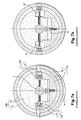
- FIG. 7a A specific example for a construction of a movable exciting system of the present invention is shown in figures 7a and b with figure 7a showing the system in the cooling position and figure 7b in the operation position.
- the upper large segment 12b is stationary and fixed to the rotating element 3
- the bottom large segment 12a and the right and left small segments 13a and 13b, respectively, are designed to be movable in radial direction toward the rotating element 3.
- Figure 7a shows the position of each segment in the cooling position.
- the upper large segment 12b with exciting system 10 and support body 11 is fastened to the rotating element 3.
- the upper large segment 12b is stationary, that means it does not take part in the movement of the segments of the exciting system 10 toward each other for activation.
- the bottom large segment 12a is movable in radial direction relative to the upper large segment 12b.
- the upper and bottom large segments 12a, b have a mating design allowing moving of the bottom large segment 12a toward the upper large segment 12b and leaving sufficiently dimensioned recesses for reception of the small segments 13a, b.
- movement of the movable segments 12a and 13a, b is done by suitable adjustment means 15 e.g. screws such as clamping bolts or adjustment screws wherein on adjusting the screw the respective segment is moved.
- suitable adjustment means 15 e.g. screws such as clamping bolts or adjustment screws wherein on adjusting the screw the respective segment is moved.
- Each movable segment 12a, 13a, b is connected to the stationary upper large segment 12b via such a screw, one segment comprising a recess for reception of the screw head and the respective counterpart a recess with a thread such as tapped hole for allowing screwing - in the threaded portion of the respective screw.
- the head of the screws for moving the small segments 13a, 13b is positioned within an appropriate recess in the small segments and the respective thread within the support body 11 of the stationary upper large segment 12b; and the head of the screw for moving the bottom large segment 12a is positioned within an appropriate recess in the upper large segment 12b and the corresponding thread within the bottom large segment 12a.
- a nut or other suitable means can be provided.
- the segments 12a, 13a, b are movable by turning the screws 15 either by hand or by an actuator.
- the movable segments 12a, 13a, b are transversed toward the operation position shown in figure 7b with the exciting system 10 forming a circle.
- segments 12a, b and 13a, b are pressed against reinforcing tube 14 and, further, by clamping the small segments 13a, b between the large segments 12a, b compressive stress can be generated for further stabilisation.
Landscapes
- Engineering & Computer Science (AREA)
- General Engineering & Computer Science (AREA)
- Mechanical Engineering (AREA)
- Magnetic Bearings And Hydrostatic Bearings (AREA)
- Connection Of Motors, Electrical Generators, Mechanical Devices, And The Like (AREA)
Abstract
Description
- The present invention is directed to a magnetic bearing comprising a rotating element, e.g. a shaft, within a stator element with a high temperature superconductor wherein the rotating element is held in a contactless state of suspension by magnetic forces.
- If a high temperature superconductor is located in the field of a permanent magnet at a temperature above its transition temperature Tc, a magnetic flux will pass therethrough. If, in this case, the superconductor is cooled to a temperature below Tc then a portion of the magnetic flux will remain frozen into the superconducting material. In the event of position change due to field changes shielding currents are induced in the superconductor by the permanent magnet which counteract the change of position. The resulting forces may be repulsive or attractive but are directed such that they counteract any deflection from the cooling position.
- Using this principle non-contact making and, thus, essentially frictionless, self stabilizing magnetic bearings can be constructed.
Such bearings contain arrangements of permanent magnets as exciting system and a high temperature superconductor. - A generic bearing is disclosed in
DE 44 36 831 C2 . In general, such bearings comprise the following parts: - A first bearing part tightly attached to a shaft and being surrounded by a second, fixed positioned bearing part, wherein the second bearing part is associated with a stator, and a bearing gap is formed between the first and second bearing parts. The first bearing part contains an arrangement of a plurality of alternately polarized permanent magnets between which there are ferromagnetic elements. The second bearing part contains a superconducting structure, and a cooling apparatus for cooling the superconducting structure below Tc of the superconductor material. Here, the first bearing part is formed of a large number of permanent magnets which are in the form of annular discs and are located one after the other in the axial direction on the rotor shaft. These elements are polarized such that the polarisation alternates when seen in the axial direction of the shaft. Comparatively thin ferromagnetic intermediate elements are arranged in each case between adjacent permanent magnets. These ferromagnetic intermediate elements serves to magnetically concentrate the magnetic lines or force of adjacent permanent magnets, so that a particularly high magnetic field strength is produced on the side of each intermediate element which faces the bearing gap. This first bearing part of the rotor body with its magnet arrangement composed of permanently magnetic elements, is surrounded by the second fixed-position bearing part of the stator. This second bearing part contains a superconducting structure.
- In the above arrangement since the stator element with the superconductor surrounds essentially concentrically the rotor element with the exciting system upon cooling below Tc the magnetic force generated keep the rotor element at its position in free suspension.
However, the actual position of the rotor element after cooling depends also on the own weight of the rotor element as well as the working load generally causing a deflection of the rotor element from the cooling position to the so called operation position. - To obtain stable and stiff bearing of the rotor element the strength of the magnetic forces acting between the superconductor and the exciting system should be desirably as high as possible.
- Generally, depending on the distance between the superconductor and its exciting system during cooling (cooling position) the resulting force - distance characteristics are different:
If the distance is relatively large (Zero Field Cooling = ZFC) so that virtually no magnetic field acts on the superconductor during cooling in the result repulsive forces are obtained which increase progressively on approach. - If the distance is close during cooling (Maximum Field Cooling = MFC) on being moved away from each other, at first, attracting forces are obtained which increase until a maximum and, then, decrease.
- Taking into account the above force-distance characteristics a stable and stiff bearing of the rotor element requires displacement from the cooling position.
- In
WO 02/06688 A1
In order to enable deflection from the cooling position into the operation position the cylindrical superconductor is divided into at least 2 circle segment-shaped partial shells which can be displaced with respect to each other in radial direction by a suitable driving mechanism (actuator). By movement of the partial shells the radial distance between the superconductor and the exciting system can be changed. Here, in the cooling position the partial shells are moved away from each other so that the radial distance at the cooling position is larger than in the operation position. - As set out above, cooling of the superconductor below its Tc is necessary which, for example, for the well known YBa2Cu3O superconductor is 70K. Thus, it is necessary that the stator with the superconductor is housed in a tightly sealed cooling device, e.g a dewar, with very good heat insulation properties. Usually, vacuum tight cryogenic chambers are used wherein the stator element with the superconductor is housed in the vacuum sealed cooling jacket and the rotor element is positioned within the interior warm bore of the cryogenic device.
- However, there are several problems associated with a movable stator arrangement within a tightly sealed cooling chamber.
First of all, the driving mechanism for moving the partial superconductor shells must be able to work with high reliability even at very low temperatures. Moreover, the mechanism must be able to withstand the high temperature differences between the warm and the cold state. For example, the material of which the driving mechanism is made must have high dimensional stability even when cooled to very low temperatures, that is, the thermal expansion coefficient must be suitably low.
Due to this requirements a driving mechanism for operation at low temperatures is costly and restricted to specific materials only.
Further, such movable mechanically stressed mechanisms is inherently prone to repair. However, there is the disadvantage that in case of defect not only the stator with the high temperature superconductor material must be brought to room temperature but, further, the sealed cooling chamber must be opened and after the defect is cured the chamber must be sealed again and brought to the low temperature of Tc which renders any repair costly and troublesome. - If otherwise the driving mechanism is located outside the cooling chamber a connection between the cold interior and the warm outside is required, which is also disadvantageous.
- According to the present invention the above problems are solved by a magnetic bearing with a fixed positioned stator element and a rotor element with at least one permanent magnet with annularly arrangement for exciting the superconductor of the stator wherein the annularly arranged permanent magnet is composed of at least two segments which are movable in relation to the superconductor of the stator.
- That is, according to the present invention a magnetic bearing is provided for contactless bearing of a rotor element within a stator element wherein the stator element comprises a superconductor and surrounds the rotor element, wherein the rotor element comprises a rotating element such as a shaft, wherein at least one permanent magnet is annularly arranged concentrically around the rotating element and wherein the at least one annularly arranged permanent magnet is composed of at least two segments which are movable in relation to the superconductor of the stator.
- Since according to the present invention the superconductor of the stator is fixedly positioned the stator element can be easily housed within an isolated cold chamber of a cryogenic device which is tightly sealed without the need of providing a driving mechanism which must withstand the temperature differences on cooling and without the need of mechanically stressed parts which are liable to repair, so that any untimely interruption of the operation of the magnetic bearing due to defects of the driving mechanism can be avoided.
- In the following the present invention is explained in further detail with reference to figures specific embodiments for a better illustration. It ls shown in
- figure 1
- the general design of a superconducting magnetic bearing;
- figure 2
- a diagram of the force-distance curve of a magnetic bearing according to the present invention ;
- figure 3
- a diagram of the force-distance curve of another embodiment of the present invention;
- figure 4
- a cross-section through a magnetic bearing according to the present invention at the cooling position;
- figure 5
- a cross section through the embodiment according to figure 3 in the operation position;
- figure 6
- a cross-section being an enlarged quarter segment of the embodiment of figures 4 and 5; and
- figures 7a, b
- a cross-section through a rotor element of a magnetic bearing of the present invention.
- Figure 1 shows the general design of a magnetic bearing wherein the housing of the
cooling device 16 is partially removed.
The magnetic bearing has an overall cylindrical shape. Thestator element 1 is composed of a cylindricallyshaped superconductor 5 and a thermallyconductive member 6 which is mounted on the outer surface of thesuperconductor 5.Supports 19 are provided for supporting the part with thesuperconductor 5 toward the interior of the wall of the cooling device. - Here, the
rotor element 2 has ahorizontal shaft 3 surrounded by anexciting system 10 with an arrangement of alternatingpermanent magnets 17 andflux collection poles 18. Thestator element 1 is housed within the jacket of thecooling device 16 and therotor element 2 within the interior warm bore of thecooling device 16 which is at room temperature. - For illustration of the dependence of the strength of the magnetic force on the cooling distance between a superconductor component and its exciting system in figures 2 and 3 the shape of the force-distance curve for two different systems is shown. In the diagrams the x-coordinate indicates the distance between the superconductor component and its exciting system with point zero being the position of the permanent magnet on cooling and the y-coordinate indicates the magnetic force generated on approaching.
- For measurement permanent magnets made of iron-neodymium-boron (FeNdB) were used provided with a load cell.
- The curve in figure 2 shows the course of the force on zero field cooling with the force increasing exponentially on approaching of the exciting systems, e. i. permanent magnet, to the superconductor.
- In figure 3 the course of the curve more closely reflects the actual situation in a real magneting bearing which, in this case, has a bearing gap of 3 mm. That is, at point zero the distance between the superconductor and the permanent magnet is actually 6 mm, and at
point 3 there remains a distance corresponding to the width of the bearing gap, that is 3 mm. - In figure 2 and 3 the upper curve reflects the course of the force on approaching and the lower curve on moving away. The difference is caused by the hysteresis of the magnets.
- The shape of these curves clearly shows that for obtaining a maximal strength of the magnetic force the cooling position should be sufficiently spaced away from the operation position and, further, that in the operation position the distance between the superconductor and the exciting system should be as small as possible.
- Figures 4 and 5 show a cross section through an embodiment of an magnetic bearing according to the present invention in its operation position (figure 4) and in its cooling position (figure 5).
In the following with reference to figure 4 and 5 the design principles of a magnetic bearing according to the present invention are illustrated in more detail. - The magnetic bearing shown in figure 4 has in principle a hollow cylindrical overall shape and comprises a
stator element 1 which coaxially surrounds arotor element 2. Therotor element 2 comprises a rotating element 3 - here a shaft of a machine of non magnetic material - which is positioned within a also hollow cylindrical exciting system.
In the specific embodiment shown in the figures, thestator element 1 is composed of a cylindrically shapedsuperconductor 5. On the outer surface of the superconductor 5 a thermallyconductive member 6 is mounted, which is supported toward the wall of the cooling device byspacers 7 withfree spaces 8 between thespacers 7. - The thermally
conductive member 6 serves to lead away heat from thesuperconductor 5 and, thus, is preferably made of a thermally highly conductive material such as copper. - An enlarged depiction of a quarter segment is shown in figure 6.
- The
stator element 1 is housed within the jacket of a cooling device such as a dewar, the wall thereof being indicated by the black line surrounding thestator element 1 along its outer and inner circumference. - Preferably on the inner surface of the superconductor 5 a
layer 9 of thermally insulating material can be provided for shielding the warm interior of the cooling device from the cooled jacket with thestator element 1. Suitable insulating materials are generally known in the art. - Cooling of the
stator element 1 can be conducted by a suitable refrigerating machine.
For example the refrigerating machine can be connected with the thermallyconductive member 6 for indirect cooling of the superconductors. The refrigeration machine is not shown but is as such known. For example, cryogenic coolers can be used. - For improving thermal insulation the outer surface of the
member 6 can be covered with a further layer of insulating material (not shown). - The
superconductor 5 can be composed of any high temperature superconductor material known to be suitable for bearing applications. An example of one class of suited superconductor material are the ceramic oxide high temperature superconductors.
Typical examples comprise ceramic oxide superconductors based on Y-Ae-Cu-O, (Y, Re)-Ae-Cu-O, Bi-Ae-Cu-O, (Bi, Pb)-Ae-Cu-O and (TI, Pb)-(Ae, Y)-Cu-O. in the above formula Ae means at least one alkaline earth element, particularly, Ba, Ca and Sr.
Re means at least one rare earth element, in particular, La, Lu, Sc, Sm, Nd or Yb. - Especially suitable superconductors are those known by the reference YBCO-123 and YBCO-211, wherein the numerical combinations 123 and 211 stand for the stoichiometric ratios of the elements Y, Ba and Cu. As well as those known by the reference BSCCO-2212, BSCCO-2223, wherein the numerical combinations 2212 and 2223 stand for the stoichiometric ratios of the elements Bi, Sr, Ca and Cu, in particular those, wherein part of Bi is substituted by Pb.
- Particularly preferred are superconductors produced using a molten casting method, in particular, a centrifugal casting method as disclosed, for example, in
DE-A-3 830 092 ,EP-A-0 451 532 ,EP-A-0 462 409 andEP-A-0 477 493 , to which reference is expressly made. - The cylindrically shaped
superconductor 5 can be made of a single piece or can be composed of a plurality of segments attached together to form the circular body.
In case of segments the segments preferably have a trapezoidal shape. Preferably each segment has the same dimensions. - The
spacers 7 serve to stabilize the stator arrangement within the jacket of cooling device in a fixed position.
The number and shape of thespacers 7 is not particularly critical as long as a stable fixed position of the stator arrangement is achieved. Thespacers 7 should be composed of poorly thermally conductive material such as CFRP (carbon fibre reinforced plastic) for avoiding heat introduction.
For providing effective thermal insulation thefree space 8 between thespacers 7 is preferably evacuated. Further it is also possible to fill thefree space 8 at least partially with at least one insulation means Any insulation means known can be applied suitable for this purpose. - Examples for suitable insulation materials are insulation foam, super insulation, insulating flakes or glass fibres.
- The design and materials for
exciting systems 10 for cylindrical magnetic bearings and as suitable for the present invention are generally known. Theexciting system 10 can comprise a plurality of permanent magnets which are separated from each other by elements made of ferromagnetic material such as iron.
Suitable permanent magnetic materials are for example neodymium-iron-boron (NdFeB) or samarium-cobalt-alloy (SmCo). - The permanent magnets as well as the intermediate elements can have the shape of annular discs and are arranged one behind the other on a
cylindrical support body 11 surrounding theshaft 3. - The
cylindrical support body 11 is preferably made of a non magnetic material such as steel.
Preferably in axial direction the first and last member of the stack composed of permanent magnets and intermediate members is an intermediate member. - As shown in figure 5 the arrangement of
exciting system 10 andsupport body 11 is divided into segments which can be moved in relation to each other in radial direction.
The segments can have a mirror-image symmetry. That is, as shown in figure 5 each segment is opposed by a mirror-imaged counterpart. - In the embodiment of figure 5 there are two large and two
small segments 12a, b; 13a, b which can be moved in relation to each other in radial direction. For bringing the arrangement into the cooling position the twosmall segments 13a, b are shifted toward theshaft 3 until a position inside a free space between theshaft 3 and thesupport body 11, that is the twosmall segments 13a, b are brought into a position which allows the twolarge segments 12a, b to be shifted towards each other. Thus, the distance between thesuperconductor 5 and theexciting system 10 can be changed allowing activation of the magnetic force. - According to an alternative the exciting system can be divided into three magnets, which can have same or different size.
- As already referred to above the operation position of the shaft depends not only on the magnetic forces but also on the own weight of the shaft and the working load.
For adjusting the desired operation position of theshaft 3 the radial distances of the segments can be selected accordingly. That is, different radial distances can be selected for the segments in the cooling position. - Generally, the number, size and shape of the segments are selected according to need in consideration of the overall construction of the respective magnetic bearing. For example, it should be taken into account that the distance between the superconductor and the exciting system should be as long as possible in the cooling position and that an optimal stiffness is obtained.
- Otherwise, since the distance between the
superconductor 5 and theexciting system 10 should be as small as possible in the operation position preferably thebearing gap 4 should be as small as possible. - Further, one or more of the segments can be stationary positioned with one or more others being movable.
Generally the specific design of the exciting system can vary depending on the demands of the concrete application and in view of the desired bearing force and stiffness of the system. - For moving the segments the exciting system can be connected to a commen actuator There is no particular restriction with respect to the kind of actuator.
- For radial movement of the segments the exciting system can be, for example, constructed in accordance to the principles of a lathe chuck or a clamping chuck. Any other suitable construction can be also used.
- Preferably, the outer limit of the moving path of the segments composing the exciting system, is defined by a
tube 14 of poorly thermally conductive material such as CFRP
By thetube 14, simultaneously, the overall assembly of the magnetic bearing of the present invention is mechanically stabilized, which is particularly advantageous in case of high revolution speeds. - A specific example for a construction of a movable exciting system of the present invention is shown in figures 7a and b with figure 7a showing the system in the cooling position and figure 7b in the operation position.
- According to this example the upper
large segment 12b is stationary and fixed to therotating element 3, the bottomlarge segment 12a and the right and leftsmall segments rotating element 3. - Figure 7a shows the position of each segment in the cooling position.
The upperlarge segment 12b withexciting system 10 andsupport body 11 is fastened to therotating element 3. The upperlarge segment 12b is stationary, that means it does not take part in the movement of the segments of theexciting system 10 toward each other for activation. - The bottom
large segment 12a is movable in radial direction relative to the upperlarge segment 12b. - As the bottom
large segment 12a the right and leftsmall segments rotating element 3 - The upper and bottom
large segments 12a, b have a mating design allowing moving of the bottomlarge segment 12a toward the upperlarge segment 12b and leaving sufficiently dimensioned recesses for reception of thesmall segments 13a, b. - In this specific example movement of the
movable segments movable segment large segment 12b via such a screw, one segment comprising a recess for reception of the screw head and the respective counterpart a recess with a thread such as tapped hole for allowing screwing - in the threaded portion of the respective screw.
In the embodiment of figure 7 the head of the screws for moving thesmall segments support body 11 of the stationary upperlarge segment 12b; and the head of the screw for moving the bottomlarge segment 12a is positioned within an appropriate recess in the upperlarge segment 12b and the corresponding thread within the bottomlarge segment 12a. - For fixation of the screw head a nut or other suitable means can be provided.
Thesegments screws 15 either by hand or by an actuator. - For activation the
movable segments exciting system 10 forming a circle. - For improving the stabilisation of the overall construction, preferably,
segments 12a, b and 13a, b are pressed against reinforcingtube 14 and, further, by clamping thesmall segments 13a, b between thelarge segments 12a, b compressive stress can be generated for further stabilisation. - The above example for movement of the segments of the
exciting system 11 is only for illustrative purposes. There is no restriction and any other suitable means for moving the segments can be used for the present invention. - Moreover, different segmentation of the exciting system 10 (inclusive support member 11) as well as different movable segments can be chosen.
- By the magnetic bearing of the present invention with the exciting system being within the non insulated warm bore of a cryogenic device rotating sealings are avoided. Further high insulating vacuum and long term sealing of the cryogenic device as well as easy change of bearing and rotor in case of defects are possible. Further, with the present invention a frictional connection of the exciting system on the shaft is possible, so that it is not necessary to provide a co-rotating damping.
-
- 1
- stator element
- 2
- rotor element
- 3
- rotating element
- 4
- bearing gap
- 5
- superconductor
- 6
- thermally conductive member
- 7
- spacer
- 8
- free space
- 9
- insulating layer
- 10
- exciting system
- 11
- support body
- 12a
- large segment (bottom)
- 12b
- large segment (upper)
- 13a
- small segment (right)
- 13b
- small segment (left)
- 14
- tube
- 15
- adjustment means
- 16
- cooling device
- 17
- permanent magnets
- 18
- flux collection poles
- 19
- support
Claims (8)
- A magnetic bearing for holding a rotating element (3) in a floating condition comprising a stator element (1) and a rotor element (2),
wherein the stator element (1) surrounds the rotor element (2) and comprises a fixed positioned superconductor (5),
wherein within the rotor element (2) around the rotating element (3) an exciting system (10) of permanent magnets is annularly arranged,
wherein the exciting system (10) is composed of a plurality of segments (12a, b; 13a, b) with one or more segments (12a, b; 13a, b) being movable in relation to each other. - Magnetic bearing according to claim 1,
wherein the segments (12a, b; 13a, b) are arranged in a mirror-imaged symmetry to each other. - Magnetic bearing according to claim 1 or 2,
wherein the segments (12a, b; 13a, b) are movable in radial direction. - Magnetic bearing according to any of the preceding claims,
wherein the exciting system (10) is attached to the shaft (3) in frictional connection. - Magnetic bearing according to any of the preceding claims,
wherein a tube 14 is provided which surrounds the exciting system (10) and defines the limit of the moving path of the one or more movable segments (12a, b; 13a, b). - Magnetic bearing according to any of the preceding claims,
wherein adjustment means 15 are provided for moving the movable segments (12a, b; 13a, b) of the exciting system 10. - Magnetic bearing according to claim 6,
wherein the adjustment means 15 are selected from a group consisting of clamping bolts and adjustment screws. - Magnetic bearing according to any of the preceding claims,
wherein at least one segment (12b) is stationary and the other segments (12a, 13a, b) are movable in radial direction towards the stationary segment (12b) by the adjustment means (15).
Priority Applications (6)
| Application Number | Priority Date | Filing Date | Title |
|---|---|---|---|
| AT06300237T ATE447116T1 (en) | 2006-03-16 | 2006-03-16 | HIGH TEMPERATURE SUPERCONDUCTIVE MAGNETIC BEARING |
| DE602006010022T DE602006010022D1 (en) | 2006-03-16 | 2006-03-16 | High temperature superconducting magnetic bearing |
| EP06300237A EP1835188B1 (en) | 2006-03-16 | 2006-03-16 | High temperature superconducting magnetic bearing |
| ES06300237T ES2335303T3 (en) | 2006-03-16 | 2006-03-16 | HIGH TEMPERATURE MAGNETIC SUPERCONDUCTOR BEARING. |
| US11/715,270 US20070222315A1 (en) | 2006-03-16 | 2007-03-07 | High temperature superconducting magnetic bearing |
| JP2007060589A JP2007247896A (en) | 2006-03-16 | 2007-03-09 | High temperature superconduction magnetic bearing |
Applications Claiming Priority (1)
| Application Number | Priority Date | Filing Date | Title |
|---|---|---|---|
| EP06300237A EP1835188B1 (en) | 2006-03-16 | 2006-03-16 | High temperature superconducting magnetic bearing |
Publications (2)
| Publication Number | Publication Date |
|---|---|
| EP1835188A1 true EP1835188A1 (en) | 2007-09-19 |
| EP1835188B1 EP1835188B1 (en) | 2009-10-28 |
Family
ID=36930349
Family Applications (1)
| Application Number | Title | Priority Date | Filing Date |
|---|---|---|---|
| EP06300237A Expired - Lifetime EP1835188B1 (en) | 2006-03-16 | 2006-03-16 | High temperature superconducting magnetic bearing |
Country Status (6)
| Country | Link |
|---|---|
| US (1) | US20070222315A1 (en) |
| EP (1) | EP1835188B1 (en) |
| JP (1) | JP2007247896A (en) |
| AT (1) | ATE447116T1 (en) |
| DE (1) | DE602006010022D1 (en) |
| ES (1) | ES2335303T3 (en) |
Cited By (3)
| Publication number | Priority date | Publication date | Assignee | Title |
|---|---|---|---|---|
| DE102008028588A1 (en) | 2008-06-18 | 2009-12-24 | Schaeffler Kg | Magnetic bearings with high-temperature superconducting elements |
| CN103527629A (en) * | 2013-10-18 | 2014-01-22 | 中国科学院电工研究所 | Superconducting magnetic levitation supporting device with permanent magnetic ring |
| WO2023201220A1 (en) | 2022-04-12 | 2023-10-19 | Chart Energy & Chemicals, Inc. | Cryogenic expansion turbine with magnetic bearings |
Families Citing this family (3)
| Publication number | Priority date | Publication date | Assignee | Title |
|---|---|---|---|---|
| US8078242B2 (en) * | 2009-04-15 | 2011-12-13 | Dynamo Capital, Inc. | Internal impedance converting superconducting acyclic power converter |
| CN103825427B (en) * | 2014-03-13 | 2016-01-13 | 华中科技大学 | A kind of moment conducting structure for superconducting motor |
| JP2016063671A (en) * | 2014-09-19 | 2016-04-25 | 株式会社明電舎 | Stator manufacturing method |
Citations (11)
| Publication number | Priority date | Publication date | Assignee | Title |
|---|---|---|---|---|
| DE3830092A1 (en) | 1988-09-03 | 1990-03-15 | Hoechst Ag | METHOD FOR THE PRODUCTION OF A HIGH-TEMPERATURE SUPERCONDUCTOR AND MOLDED BODY THEREOF |
| US4956571A (en) * | 1989-03-01 | 1990-09-11 | Mpb Corporation | Superconducting magnetic bearing |
| EP0451532A1 (en) | 1990-04-11 | 1991-10-16 | Hoechst Aktiengesellschaft | Process for producing a high temperature superconductor |
| EP0462409A1 (en) | 1990-06-18 | 1991-12-27 | Hoechst Aktiengesellschaft | Process for the production of tube shaped mouldings out of high temperature superconductor material and plant for carrying out this process |
| EP0477493A2 (en) | 1990-08-17 | 1992-04-01 | Hoechst Aktiengesellschaft | Process for producing bodies from preforms of oxide high temperature superconductors |
| US5117139A (en) * | 1991-04-17 | 1992-05-26 | The Unites States Of America As Represented By The United States National Aeronautics And Space Administration | Superconducting bearings with levitation control configurations |
| DE4436831A1 (en) * | 1993-12-13 | 1995-06-14 | Siemens Ag | Unit for magnetic orientation of rotor shaft |
| JPH08200368A (en) * | 1995-01-25 | 1996-08-06 | Nippon Seiko Kk | Superconducting magnetic bearing device |
| DE19850421A1 (en) * | 1998-11-02 | 2000-05-11 | Gutt Hans Joachim | Self-adjustment device for high-temperature superconductive magnet passive bearing e.g. for electrical machine rotor, has energising coil and ferromagnetic armature operating as electrical adjustment drive |
| WO2002006688A1 (en) | 2000-07-18 | 2002-01-24 | Atlas Copco Energas Gmbh | Magnetic bearing assembly |
| JP2003214429A (en) * | 2002-01-22 | 2003-07-30 | Mitsubishi Heavy Ind Ltd | Superconducting magnetic bearing |
Family Cites Families (13)
| Publication number | Priority date | Publication date | Assignee | Title |
|---|---|---|---|---|
| US4577116A (en) * | 1983-11-14 | 1986-03-18 | The Boeing Company | System for providing electrical energy to a missile and the like |
| FR2695968B1 (en) * | 1992-09-22 | 1994-12-23 | Aerospatiale | Magnetic bearing device with mechanical stop for positioning a rotating body with respect to a stator body. |
| CN1099153C (en) * | 1998-04-08 | 2003-01-15 | 塞莫·布莱克·克劳森公司 | Pulp processing equipment, disc homogenizer and screen and method for processing pulp suspension |
| US6441521B1 (en) * | 2000-05-12 | 2002-08-27 | Reliance Electric Technologies, Llc | Hybrid superconducting motor/generator |
| DE10026003A1 (en) * | 2000-05-25 | 2001-12-06 | Bosch Gmbh Robert | stator |
| US6608417B1 (en) * | 2000-09-05 | 2003-08-19 | Global Trading & Technology, Inc. | Super conductive bearing |
| US6879075B2 (en) * | 2003-01-31 | 2005-04-12 | Curtiss-Wright Electro-Mechanical Corporation | Trapezoidal shaped magnet flux intensifier motor pole arrangement for improved motor torque density |
| TWI223488B (en) * | 2003-03-25 | 2004-11-01 | Delta Electronics Inc | Motor rotor and manufacture method thereof |
| DE10335040B4 (en) * | 2003-08-01 | 2009-09-03 | Siemens Ag | Electric machine with ferromagnetic pole core of its rotor |
| ITMI20032241A1 (en) * | 2003-11-18 | 2005-05-19 | Sisme Immobiliare S P A | ROLLER WITH PERMANENT MAGNETS FOR FAST ASSEMBLY ELECTRIC MOTOR AND METHOD FOR ITS ACHIEVEMENT |
| US7285890B2 (en) * | 2005-03-30 | 2007-10-23 | Comprehensive Power, Inc. | Magnet retention on rotors |
| ES2337365T3 (en) * | 2005-04-22 | 2010-04-23 | Infranor Holding S.A. | PERMANENT MAGNET FIXING SYSTEM. |
| GB2438443A (en) * | 2006-05-27 | 2007-11-28 | Converteam Ltd | Rotor magnet retaining arrangement suitable for low-speed large-diameter electrical generators |
-
2006
- 2006-03-16 EP EP06300237A patent/EP1835188B1/en not_active Expired - Lifetime
- 2006-03-16 AT AT06300237T patent/ATE447116T1/en not_active IP Right Cessation
- 2006-03-16 DE DE602006010022T patent/DE602006010022D1/en not_active Expired - Lifetime
- 2006-03-16 ES ES06300237T patent/ES2335303T3/en not_active Expired - Lifetime
-
2007
- 2007-03-07 US US11/715,270 patent/US20070222315A1/en not_active Abandoned
- 2007-03-09 JP JP2007060589A patent/JP2007247896A/en not_active Withdrawn
Patent Citations (12)
| Publication number | Priority date | Publication date | Assignee | Title |
|---|---|---|---|---|
| DE3830092A1 (en) | 1988-09-03 | 1990-03-15 | Hoechst Ag | METHOD FOR THE PRODUCTION OF A HIGH-TEMPERATURE SUPERCONDUCTOR AND MOLDED BODY THEREOF |
| US4956571A (en) * | 1989-03-01 | 1990-09-11 | Mpb Corporation | Superconducting magnetic bearing |
| EP0451532A1 (en) | 1990-04-11 | 1991-10-16 | Hoechst Aktiengesellschaft | Process for producing a high temperature superconductor |
| EP0462409A1 (en) | 1990-06-18 | 1991-12-27 | Hoechst Aktiengesellschaft | Process for the production of tube shaped mouldings out of high temperature superconductor material and plant for carrying out this process |
| EP0477493A2 (en) | 1990-08-17 | 1992-04-01 | Hoechst Aktiengesellschaft | Process for producing bodies from preforms of oxide high temperature superconductors |
| US5117139A (en) * | 1991-04-17 | 1992-05-26 | The Unites States Of America As Represented By The United States National Aeronautics And Space Administration | Superconducting bearings with levitation control configurations |
| DE4436831A1 (en) * | 1993-12-13 | 1995-06-14 | Siemens Ag | Unit for magnetic orientation of rotor shaft |
| DE4436831C2 (en) | 1993-12-13 | 1997-09-11 | Siemens Ag | Magnetic bearing of a rotor shaft using high-T¶c¶ superconductor material |
| JPH08200368A (en) * | 1995-01-25 | 1996-08-06 | Nippon Seiko Kk | Superconducting magnetic bearing device |
| DE19850421A1 (en) * | 1998-11-02 | 2000-05-11 | Gutt Hans Joachim | Self-adjustment device for high-temperature superconductive magnet passive bearing e.g. for electrical machine rotor, has energising coil and ferromagnetic armature operating as electrical adjustment drive |
| WO2002006688A1 (en) | 2000-07-18 | 2002-01-24 | Atlas Copco Energas Gmbh | Magnetic bearing assembly |
| JP2003214429A (en) * | 2002-01-22 | 2003-07-30 | Mitsubishi Heavy Ind Ltd | Superconducting magnetic bearing |
Non-Patent Citations (2)
| Title |
|---|
| PATENT ABSTRACTS OF JAPAN vol. 1996, no. 12 26 December 1996 (1996-12-26) * |
| PATENT ABSTRACTS OF JAPAN vol. 2003, no. 11 5 November 2003 (2003-11-05) * |
Cited By (5)
| Publication number | Priority date | Publication date | Assignee | Title |
|---|---|---|---|---|
| DE102008028588A1 (en) | 2008-06-18 | 2009-12-24 | Schaeffler Kg | Magnetic bearings with high-temperature superconducting elements |
| US8618707B2 (en) | 2008-06-18 | 2013-12-31 | Schaeffler Technologies AG & Co. KG | Magnetic bearing with high-temperature superconductor elements |
| CN103527629A (en) * | 2013-10-18 | 2014-01-22 | 中国科学院电工研究所 | Superconducting magnetic levitation supporting device with permanent magnetic ring |
| CN103527629B (en) * | 2013-10-18 | 2016-05-18 | 中国科学院电工研究所 | With the super-conductive magnetic suspension supporting arrangement of permanent-magnetic clamp |
| WO2023201220A1 (en) | 2022-04-12 | 2023-10-19 | Chart Energy & Chemicals, Inc. | Cryogenic expansion turbine with magnetic bearings |
Also Published As
| Publication number | Publication date |
|---|---|
| ES2335303T3 (en) | 2010-03-24 |
| EP1835188B1 (en) | 2009-10-28 |
| JP2007247896A (en) | 2007-09-27 |
| US20070222315A1 (en) | 2007-09-27 |
| ATE447116T1 (en) | 2009-11-15 |
| DE602006010022D1 (en) | 2009-12-10 |
Similar Documents
| Publication | Publication Date | Title |
|---|---|---|
| US6806604B2 (en) | Centrifuge with a magnetically stabilized rotor for centrifugal goods | |
| US6762522B2 (en) | Magnetic bearing for suspending a rotating shaft using high Tc superconducting material | |
| US6777841B2 (en) | Device comprising a rotor and a magnetic suspension bearing for the contactless bearing of the rotor | |
| EP0558818A1 (en) | Superconducting bearings | |
| US20070222315A1 (en) | High temperature superconducting magnetic bearing | |
| EP0719471B1 (en) | Superconducting rotor | |
| US6737777B2 (en) | Magnetic bearing and use thereof | |
| US6831384B2 (en) | Magnetic bearing | |
| CN201461737U (en) | A High Temperature Superconducting Magnetic Suspension Radial Bearing | |
| KR101836550B1 (en) | Device and method for the damped, non-contact support of a coolant feed line for superconducting machines | |
| Walter et al. | First heavy load bearing for industrial application with shaft loads up to 10 kN | |
| KR20050051547A (en) | Magnetic bearing | |
| Murakami et al. | Design of an energy storage flywheel system using permanent magnet bearing (PMB) and superconducting magnetic bearing (SMB) | |
| US5117139A (en) | Superconducting bearings with levitation control configurations | |
| US7944105B2 (en) | Synchronous machine having magnetic bearings excited by the rotor | |
| JP7237537B2 (en) | rotating machine | |
| US6798095B2 (en) | Device including component, which is ferromagnetic in cryogenic temperature range and can be subjected to mechanical loads | |
| EP1767798A1 (en) | Superconducting magnetic bearing | |
| Nicolsky et al. | Superconducting axial bearing for induction machines with active radial magnetic bearings | |
| Werfel et al. | Encapsulated HTS bearings: technical and cost considerations | |
| Kummeth et al. | Development and characterization of magnetic HTS bearings for a 400 kW synchronous HTS motor | |
| Siems et al. | Advances in the design of superconducting magnetic bearings for static and dynamic applications | |
| JP4473470B2 (en) | Centrifuge with rotor provided to receive centrifuge product | |
| Werfel et al. | Operation and design selection of high temperature superconducting magnetic bearings | |
| KR100572460B1 (en) | Superconducting Journal Bearing |
Legal Events
| Date | Code | Title | Description |
|---|---|---|---|
| PUAI | Public reference made under article 153(3) epc to a published international application that has entered the european phase |
Free format text: ORIGINAL CODE: 0009012 |
|
| AK | Designated contracting states |
Kind code of ref document: A1 Designated state(s): AT BE BG CH CY CZ DE DK EE ES FI FR GB GR HU IE IS IT LI LT LU LV MC NL PL PT RO SE SI SK TR |
|
| AX | Request for extension of the european patent |
Extension state: AL BA HR MK YU |
|
| 17P | Request for examination filed |
Effective date: 20080319 |
|
| AKX | Designation fees paid |
Designated state(s): AT BE BG CH CY CZ DE DK EE ES FI FR GB GR HU IE IS IT LI LT LU LV MC NL PL PT RO SE SI SK TR |
|
| GRAP | Despatch of communication of intention to grant a patent |
Free format text: ORIGINAL CODE: EPIDOSNIGR1 |
|
| GRAS | Grant fee paid |
Free format text: ORIGINAL CODE: EPIDOSNIGR3 |
|
| GRAA | (expected) grant |
Free format text: ORIGINAL CODE: 0009210 |
|
| AK | Designated contracting states |
Kind code of ref document: B1 Designated state(s): AT BE BG CH CY CZ DE DK EE ES FI FR GB GR HU IE IS IT LI LT LU LV MC NL PL PT RO SE SI SK TR |
|
| REG | Reference to a national code |
Ref country code: GB Ref legal event code: FG4D |
|
| REG | Reference to a national code |
Ref country code: CH Ref legal event code: EP |
|
| REG | Reference to a national code |
Ref country code: IE Ref legal event code: FG4D |
|
| REF | Corresponds to: |
Ref document number: 602006010022 Country of ref document: DE Date of ref document: 20091210 Kind code of ref document: P |
|
| REG | Reference to a national code |
Ref country code: ES Ref legal event code: FG2A Ref document number: 2335303 Country of ref document: ES Kind code of ref document: T3 |
|
| LTIE | Lt: invalidation of european patent or patent extension |
Effective date: 20091028 |
|
| NLV1 | Nl: lapsed or annulled due to failure to fulfill the requirements of art. 29p and 29m of the patents act | ||
| PG25 | Lapsed in a contracting state [announced via postgrant information from national office to epo] |
Ref country code: FI Free format text: LAPSE BECAUSE OF FAILURE TO SUBMIT A TRANSLATION OF THE DESCRIPTION OR TO PAY THE FEE WITHIN THE PRESCRIBED TIME-LIMIT Effective date: 20091028 Ref country code: LT Free format text: LAPSE BECAUSE OF FAILURE TO SUBMIT A TRANSLATION OF THE DESCRIPTION OR TO PAY THE FEE WITHIN THE PRESCRIBED TIME-LIMIT Effective date: 20091028 Ref country code: IS Free format text: LAPSE BECAUSE OF FAILURE TO SUBMIT A TRANSLATION OF THE DESCRIPTION OR TO PAY THE FEE WITHIN THE PRESCRIBED TIME-LIMIT Effective date: 20100228 Ref country code: PT Free format text: LAPSE BECAUSE OF FAILURE TO SUBMIT A TRANSLATION OF THE DESCRIPTION OR TO PAY THE FEE WITHIN THE PRESCRIBED TIME-LIMIT Effective date: 20100301 Ref country code: SE Free format text: LAPSE BECAUSE OF FAILURE TO SUBMIT A TRANSLATION OF THE DESCRIPTION OR TO PAY THE FEE WITHIN THE PRESCRIBED TIME-LIMIT Effective date: 20091028 |
|
| PGFP | Annual fee paid to national office [announced via postgrant information from national office to epo] |
Ref country code: CH Payment date: 20100325 Year of fee payment: 5 Ref country code: ES Payment date: 20100326 Year of fee payment: 5 |
|
| PG25 | Lapsed in a contracting state [announced via postgrant information from national office to epo] |
Ref country code: CY Free format text: LAPSE BECAUSE OF FAILURE TO SUBMIT A TRANSLATION OF THE DESCRIPTION OR TO PAY THE FEE WITHIN THE PRESCRIBED TIME-LIMIT Effective date: 20091028 Ref country code: SI Free format text: LAPSE BECAUSE OF FAILURE TO SUBMIT A TRANSLATION OF THE DESCRIPTION OR TO PAY THE FEE WITHIN THE PRESCRIBED TIME-LIMIT Effective date: 20091028 Ref country code: LV Free format text: LAPSE BECAUSE OF FAILURE TO SUBMIT A TRANSLATION OF THE DESCRIPTION OR TO PAY THE FEE WITHIN THE PRESCRIBED TIME-LIMIT Effective date: 20091028 Ref country code: PL Free format text: LAPSE BECAUSE OF FAILURE TO SUBMIT A TRANSLATION OF THE DESCRIPTION OR TO PAY THE FEE WITHIN THE PRESCRIBED TIME-LIMIT Effective date: 20091028 |
|
| PGFP | Annual fee paid to national office [announced via postgrant information from national office to epo] |
Ref country code: FR Payment date: 20100402 Year of fee payment: 5 |
|
| PG25 | Lapsed in a contracting state [announced via postgrant information from national office to epo] |
Ref country code: AT Free format text: LAPSE BECAUSE OF FAILURE TO SUBMIT A TRANSLATION OF THE DESCRIPTION OR TO PAY THE FEE WITHIN THE PRESCRIBED TIME-LIMIT Effective date: 20091028 Ref country code: BE Free format text: LAPSE BECAUSE OF FAILURE TO SUBMIT A TRANSLATION OF THE DESCRIPTION OR TO PAY THE FEE WITHIN THE PRESCRIBED TIME-LIMIT Effective date: 20091028 |
|
| PGFP | Annual fee paid to national office [announced via postgrant information from national office to epo] |
Ref country code: GB Payment date: 20100322 Year of fee payment: 5 |
|
| PG25 | Lapsed in a contracting state [announced via postgrant information from national office to epo] |
Ref country code: RO Free format text: LAPSE BECAUSE OF FAILURE TO SUBMIT A TRANSLATION OF THE DESCRIPTION OR TO PAY THE FEE WITHIN THE PRESCRIBED TIME-LIMIT Effective date: 20091028 Ref country code: EE Free format text: LAPSE BECAUSE OF FAILURE TO SUBMIT A TRANSLATION OF THE DESCRIPTION OR TO PAY THE FEE WITHIN THE PRESCRIBED TIME-LIMIT Effective date: 20091028 Ref country code: DK Free format text: LAPSE BECAUSE OF FAILURE TO SUBMIT A TRANSLATION OF THE DESCRIPTION OR TO PAY THE FEE WITHIN THE PRESCRIBED TIME-LIMIT Effective date: 20091028 Ref country code: BG Free format text: LAPSE BECAUSE OF FAILURE TO SUBMIT A TRANSLATION OF THE DESCRIPTION OR TO PAY THE FEE WITHIN THE PRESCRIBED TIME-LIMIT Effective date: 20100128 |
|
| PG25 | Lapsed in a contracting state [announced via postgrant information from national office to epo] |
Ref country code: CZ Free format text: LAPSE BECAUSE OF FAILURE TO SUBMIT A TRANSLATION OF THE DESCRIPTION OR TO PAY THE FEE WITHIN THE PRESCRIBED TIME-LIMIT Effective date: 20091028 Ref country code: SK Free format text: LAPSE BECAUSE OF FAILURE TO SUBMIT A TRANSLATION OF THE DESCRIPTION OR TO PAY THE FEE WITHIN THE PRESCRIBED TIME-LIMIT Effective date: 20091028 |
|
| PGFP | Annual fee paid to national office [announced via postgrant information from national office to epo] |
Ref country code: DE Payment date: 20100419 Year of fee payment: 5 Ref country code: IT Payment date: 20100325 Year of fee payment: 5 |
|
| PLBE | No opposition filed within time limit |
Free format text: ORIGINAL CODE: 0009261 |
|
| STAA | Information on the status of an ep patent application or granted ep patent |
Free format text: STATUS: NO OPPOSITION FILED WITHIN TIME LIMIT |
|
| 26N | No opposition filed |
Effective date: 20100729 |
|
| PG25 | Lapsed in a contracting state [announced via postgrant information from national office to epo] |
Ref country code: GR Free format text: LAPSE BECAUSE OF FAILURE TO SUBMIT A TRANSLATION OF THE DESCRIPTION OR TO PAY THE FEE WITHIN THE PRESCRIBED TIME-LIMIT Effective date: 20100129 Ref country code: MC Free format text: LAPSE BECAUSE OF NON-PAYMENT OF DUE FEES Effective date: 20100331 |
|
| PG25 | Lapsed in a contracting state [announced via postgrant information from national office to epo] |
Ref country code: IE Free format text: LAPSE BECAUSE OF NON-PAYMENT OF DUE FEES Effective date: 20100316 |
|
| REG | Reference to a national code |
Ref country code: CH Ref legal event code: PL |
|
| GBPC | Gb: european patent ceased through non-payment of renewal fee |
Effective date: 20110316 |
|
| REG | Reference to a national code |
Ref country code: FR Ref legal event code: ST Effective date: 20111130 |
|
| PG25 | Lapsed in a contracting state [announced via postgrant information from national office to epo] |
Ref country code: LI Free format text: LAPSE BECAUSE OF NON-PAYMENT OF DUE FEES Effective date: 20110331 Ref country code: FR Free format text: LAPSE BECAUSE OF NON-PAYMENT OF DUE FEES Effective date: 20110331 Ref country code: DE Free format text: LAPSE BECAUSE OF NON-PAYMENT OF DUE FEES Effective date: 20111001 Ref country code: CH Free format text: LAPSE BECAUSE OF NON-PAYMENT OF DUE FEES Effective date: 20110331 |
|
| REG | Reference to a national code |
Ref country code: DE Ref legal event code: R119 Ref document number: 602006010022 Country of ref document: DE Effective date: 20111001 |
|
| PG25 | Lapsed in a contracting state [announced via postgrant information from national office to epo] |
Ref country code: GB Free format text: LAPSE BECAUSE OF NON-PAYMENT OF DUE FEES Effective date: 20110316 Ref country code: IT Free format text: LAPSE BECAUSE OF NON-PAYMENT OF DUE FEES Effective date: 20110316 |
|
| REG | Reference to a national code |
Ref country code: ES Ref legal event code: FD2A Effective date: 20120424 |
|
| PG25 | Lapsed in a contracting state [announced via postgrant information from national office to epo] |
Ref country code: ES Free format text: LAPSE BECAUSE OF NON-PAYMENT OF DUE FEES Effective date: 20110317 |
|
| PG25 | Lapsed in a contracting state [announced via postgrant information from national office to epo] |
Ref country code: LU Free format text: LAPSE BECAUSE OF NON-PAYMENT OF DUE FEES Effective date: 20100316 Ref country code: NL Free format text: LAPSE BECAUSE OF FAILURE TO SUBMIT A TRANSLATION OF THE DESCRIPTION OR TO PAY THE FEE WITHIN THE PRESCRIBED TIME-LIMIT Effective date: 20091028 Ref country code: HU Free format text: LAPSE BECAUSE OF FAILURE TO SUBMIT A TRANSLATION OF THE DESCRIPTION OR TO PAY THE FEE WITHIN THE PRESCRIBED TIME-LIMIT Effective date: 20100429 |
|
| PG25 | Lapsed in a contracting state [announced via postgrant information from national office to epo] |
Ref country code: TR Free format text: LAPSE BECAUSE OF FAILURE TO SUBMIT A TRANSLATION OF THE DESCRIPTION OR TO PAY THE FEE WITHIN THE PRESCRIBED TIME-LIMIT Effective date: 20091028 |