EP1835176A2 - Two-set point pilot piston control valve - Google Patents
Two-set point pilot piston control valve Download PDFInfo
- Publication number
- EP1835176A2 EP1835176A2 EP07075140A EP07075140A EP1835176A2 EP 1835176 A2 EP1835176 A2 EP 1835176A2 EP 07075140 A EP07075140 A EP 07075140A EP 07075140 A EP07075140 A EP 07075140A EP 1835176 A2 EP1835176 A2 EP 1835176A2
- Authority
- EP
- European Patent Office
- Prior art keywords
- suction
- chamber
- cavity
- discharge
- fluid communication
- Prior art date
- Legal status (The legal status is an assumption and is not a legal conclusion. Google has not performed a legal analysis and makes no representation as to the accuracy of the status listed.)
- Withdrawn
Links
- 239000012530 fluid Substances 0.000 claims abstract description 105
- 230000007935 neutral effect Effects 0.000 claims description 14
- 230000007246 mechanism Effects 0.000 claims description 8
- 230000004044 response Effects 0.000 claims description 6
- 230000009849 deactivation Effects 0.000 claims description 4
- 238000004378 air conditioning Methods 0.000 abstract description 6
- 238000006073 displacement reaction Methods 0.000 abstract description 6
- 238000007789 sealing Methods 0.000 description 6
- 239000003507 refrigerant Substances 0.000 description 2
- 230000001419 dependent effect Effects 0.000 description 1
- 230000000694 effects Effects 0.000 description 1
- 239000000446 fuel Substances 0.000 description 1
- 230000004048 modification Effects 0.000 description 1
- 238000012986 modification Methods 0.000 description 1
Images


Classifications
-
- F—MECHANICAL ENGINEERING; LIGHTING; HEATING; WEAPONS; BLASTING
- F04—POSITIVE - DISPLACEMENT MACHINES FOR LIQUIDS; PUMPS FOR LIQUIDS OR ELASTIC FLUIDS
- F04B—POSITIVE-DISPLACEMENT MACHINES FOR LIQUIDS; PUMPS
- F04B27/00—Multi-cylinder pumps specially adapted for elastic fluids and characterised by number or arrangement of cylinders
- F04B27/08—Multi-cylinder pumps specially adapted for elastic fluids and characterised by number or arrangement of cylinders having cylinders coaxial with, or parallel or inclined to, main shaft axis
- F04B27/14—Control
- F04B27/16—Control of pumps with stationary cylinders
- F04B27/18—Control of pumps with stationary cylinders by varying the relative positions of a swash plate and a cylinder block
- F04B27/1804—Controlled by crankcase pressure
-
- F—MECHANICAL ENGINEERING; LIGHTING; HEATING; WEAPONS; BLASTING
- F04—POSITIVE - DISPLACEMENT MACHINES FOR LIQUIDS; PUMPS FOR LIQUIDS OR ELASTIC FLUIDS
- F04B—POSITIVE-DISPLACEMENT MACHINES FOR LIQUIDS; PUMPS
- F04B27/00—Multi-cylinder pumps specially adapted for elastic fluids and characterised by number or arrangement of cylinders
- F04B27/08—Multi-cylinder pumps specially adapted for elastic fluids and characterised by number or arrangement of cylinders having cylinders coaxial with, or parallel or inclined to, main shaft axis
- F04B27/14—Control
- F04B27/16—Control of pumps with stationary cylinders
- F04B27/18—Control of pumps with stationary cylinders by varying the relative positions of a swash plate and a cylinder block
- F04B27/1804—Controlled by crankcase pressure
- F04B2027/1809—Controlled pressure
- F04B2027/1813—Crankcase pressure
-
- F—MECHANICAL ENGINEERING; LIGHTING; HEATING; WEAPONS; BLASTING
- F04—POSITIVE - DISPLACEMENT MACHINES FOR LIQUIDS; PUMPS FOR LIQUIDS OR ELASTIC FLUIDS
- F04B—POSITIVE-DISPLACEMENT MACHINES FOR LIQUIDS; PUMPS
- F04B27/00—Multi-cylinder pumps specially adapted for elastic fluids and characterised by number or arrangement of cylinders
- F04B27/08—Multi-cylinder pumps specially adapted for elastic fluids and characterised by number or arrangement of cylinders having cylinders coaxial with, or parallel or inclined to, main shaft axis
- F04B27/14—Control
- F04B27/16—Control of pumps with stationary cylinders
- F04B27/18—Control of pumps with stationary cylinders by varying the relative positions of a swash plate and a cylinder block
- F04B27/1804—Controlled by crankcase pressure
- F04B2027/1822—Valve-controlled fluid connection
- F04B2027/1827—Valve-controlled fluid connection between crankcase and discharge chamber
-
- F—MECHANICAL ENGINEERING; LIGHTING; HEATING; WEAPONS; BLASTING
- F04—POSITIVE - DISPLACEMENT MACHINES FOR LIQUIDS; PUMPS FOR LIQUIDS OR ELASTIC FLUIDS
- F04B—POSITIVE-DISPLACEMENT MACHINES FOR LIQUIDS; PUMPS
- F04B27/00—Multi-cylinder pumps specially adapted for elastic fluids and characterised by number or arrangement of cylinders
- F04B27/08—Multi-cylinder pumps specially adapted for elastic fluids and characterised by number or arrangement of cylinders having cylinders coaxial with, or parallel or inclined to, main shaft axis
- F04B27/14—Control
- F04B27/16—Control of pumps with stationary cylinders
- F04B27/18—Control of pumps with stationary cylinders by varying the relative positions of a swash plate and a cylinder block
- F04B27/1804—Controlled by crankcase pressure
- F04B2027/1822—Valve-controlled fluid connection
- F04B2027/1831—Valve-controlled fluid connection between crankcase and suction chamber
-
- F—MECHANICAL ENGINEERING; LIGHTING; HEATING; WEAPONS; BLASTING
- F04—POSITIVE - DISPLACEMENT MACHINES FOR LIQUIDS; PUMPS FOR LIQUIDS OR ELASTIC FLUIDS
- F04B—POSITIVE-DISPLACEMENT MACHINES FOR LIQUIDS; PUMPS
- F04B27/00—Multi-cylinder pumps specially adapted for elastic fluids and characterised by number or arrangement of cylinders
- F04B27/08—Multi-cylinder pumps specially adapted for elastic fluids and characterised by number or arrangement of cylinders having cylinders coaxial with, or parallel or inclined to, main shaft axis
- F04B27/14—Control
- F04B27/16—Control of pumps with stationary cylinders
- F04B27/18—Control of pumps with stationary cylinders by varying the relative positions of a swash plate and a cylinder block
- F04B27/1804—Controlled by crankcase pressure
- F04B2027/184—Valve controlling parameter
- F04B2027/1854—External parameters
Definitions
- the subject invention relates to a compressor assembly for a climate control system of a vehicle, and more specifically to a variable displacement compressor assembly.
- U.S. Patent 4,606,705 discloses a variable angle wobble plate compressor assembly used in vehicle air conditioning systems.
- the compressor assembly of the '705 patent includes a compressor housing defining a suction cavity for receiving a fluid (refrigerant) at a suction pressure, a discharge cavity for receiving the fluid from the suction cavity at a discharge pressure higher than the suction pressure, and a crankcase in fluid communication with the discharge cavity.
- the crankcase encloses a variable angle wobble plate and at least one compressor piston having a variable piston stroke therein.
- a control valve for controlling a fluid pressure within the crankcase is disposed in the compressor housing.
- the control valve includes a valve casing defining a chamber therein.
- the valve casing includes a suction port in fluid communication with the suction cavity for providing the fluid at the suction pressure from the suction cavity to the chamber.
- a bellows is moveable in the chamber between an activated position and a neutral position.
- the member is responsive to the fluid at the suction pressure and is urged into the activated position when the suction pressure is below a pre-determined set-point.
- the activated position opens fluid communication between the discharge cavity and the crankcase while closing fluid communication between the suction cavity and the crankcase.
- the activated position is for pressurizing the crankcase with the fluid at the discharge pressure to decrease the angle of the wobble plate and thereby the piston stroke.
- the neutral position closes fluid communication between the discharge cavity and the crankcase while opening fluid communication between the suction cavity and the crankcase.
- the neutral position is for pressurizing the crankcase with the fluid at the suction pressure to increase the angle of the wobble plate, and thereby the piston stroke, so that the compressor assembly operates at maximum capacity.
- a solenoid is connected to the member and responsive to an electric signal for actuating the member into the activated position when the suction pressure is above the pre-determined set-point.
- the solenoid must be capable of providing a sufficient force to mechanically move the member into the activated position to allow the fluid at the discharge pressure to flow into the crankcase to de-stroke the compressor.
- the subject invention provides a compressor assembly for a climate control system of a vehicle.
- the assembly includes a compressor housing defining a suction cavity for receiving a fluid at a suction pressure, a discharge cavity for receiving the fluid from the suction cavity at a discharge pressure higher than the suction pressure, and a crankcase in fluid communication with the discharge cavity.
- the crankcase encloses a variable angle wobble plate and at least one piston having a variable piston stroke.
- a valve casing is disposed in the compressor housing and defines a chamber therein.
- a member is moveable in the chamber between an activated position and a neutral position.
- the activated position opens fluid communication between the discharge cavity and the crankcase while closing fluid communication between the suction cavity and the crankcase for pressurizing the crankcase with the fluid at the discharge pressure to decrease the piston stroke.
- the neutral position closes fluid communication between the discharge cavity and the crankcase while opening fluid communication between the suction cavity and the crankcase for pressurizing the crankcase with the fluid at the suction pressure to increase the piston stroke.
- the valve casing includes an actuator port in fluid communication with the discharge cavity for providing the fluid flow at the discharge pressure to the chamber for urging the member into the activated position in response to the fluid flow at the discharge pressure.
- variable displacement compressor assembly which uses the fluid flow at the discharge pressure from the discharge cavity, in lieu of a solenoid, to urge the member into the activated position for opening fluid communication between the discharge cavity and the crankcase to de-stroke the compressor assembly.
- FIG. 1 a compressor assembly is shown in Figure 1 generally at 20.
- the compressor assembly 20 is of the variable angle wobble plate type for use in an air conditioning system of a motor vehicle.
- the compressor assembly 20 includes a compressor housing 22 defining a suction cavity 24 for receiving a fluid (refrigerant) at a suction pressure, a discharge cavity 26 for receiving the fluid from the suction cavity 24 at a discharge pressure higher than the suction pressure, and a crankcase 28 in fluid communication with the discharge cavity 26.
- the air conditioning system includes a normal condenser 30, an orifice tube 32, an evaporator 34, and an accumulator 36, arranged in that order between the discharge cavity 26 and the suction cavity 24 respectively.
- the crankcase 28 encloses a variable angle wobble plate 38 and at least one compressor piston 40 having a variable piston stroke.
- variable stroke of the compressor pistons 40 (only two being shown), and thereby the displacement of the compressor assembly 20, is determined by the operating angle of the compressor's variable angle wobble plate 38.
- the wobble plate 38 is made to angulate by pressurizing the sealed crankcase 28 with the fluid from the discharge cavity 26 at the discharge pressure, and controlling the fluid pressure in the crankcase 28 relative to the suction pressure.
- a control valve 42 is disposed in the compressor housing 22 and is responsive to the suction pressure to increase the variable piston stroke, and thereby the displacement of the compressor assembly 20 with an increase in the suction pressure of the fluid from the suction cavity 24.
- the control valve is generally shown at 42, and includes a valve casing 44, which defines a chamber 46 therein.
- a member 48 is moveable in the chamber 46 between an activated position and a neutral position.
- the member 48 may be a bellows, a diaphragm aneroid, or any other internal suction pressure sensing element known to those skilled in the art.
- the activated position opens fluid communication between the discharge cavity 26 and the crankcase 28, while closing fluid communication between the suction cavity 24 and the crankcase 28.
- the activated position is for pressurizing the crankcase 28 with the fluid at the discharge pressure to decrease the piston stroke.
- the neutral position closes fluid communication between the discharge cavity 26 and the crankcase 28, while opening fluid communication between the suction cavity 24 and the crankcase 28 for pressurizing the crankcase 28 with the fluid at the suction pressure to increase the piston stroke.
- the fluid leaving the accumulator 36 at the suction pressure enters the suction cavity 24 of the compressor assembly 20 and is discharged to the discharge cavity 26 of the compressor assembly 20 at the discharge pressure, and thence to the condenser at a certain rate, which is dependent upon the angle of the wobble plate 38.
- the fluid from the suction cavity 24 at the suction pressure is transmitted to the control valve 42 to act on the member 48, which tends to expand in response to a decrease in the suction pressure once the suction pressure falls below a pre-determined set-point.
- the member 48 provides a force to an output rod 50, which opens a crankcase charge port 52 by lifting a ball valve 54.
- the crankcase charge port 52 when open, communicates the fluid at the discharge pressure in the discharge cavity 26 with the crankcase 28 via a crankcase port 56.
- the fluid from the discharge cavity 26 at the discharge pressure acts on the ball valve 54 in opposition to the member 48 to urge the ball valve 54 and the member 48 into the neutral position when the suction pressure of the fluid from the suction cavity 24 is above the pre-determined set-point.
- the pressure biases between the suction pressure and the discharge pressure are in addition to a spring bias from the member 48, which act to normally condition the member 48 in the neutral position to thereby normally effect maximum compressor displacement by establishing a zero crankcase 28 suction pressure differential.
- the valve casing 44 includes a cylindrical central portion 58 having a closed end 60.
- the central portion 58 of the valve casing 44 defines the chamber 46 therein.
- the member 48 is disposed within the chamber 46 defined by the central portion 58 of the valve casing 44.
- the closed end 60 of the central portion 58 of the valve casing 44 defines an actuator port 62 in fluid communication with the discharge cavity 26.
- the actuator port 62 includes a diameter (d ap ) sufficient in size to provide the fluid flow at the discharge pressure to the chamber 46. The fluid flow at the discharge pressure urges the member 48 into the activated position.
- the control valve 42 includes a control mechanism generally indicated at 64, for opening the actuator port 62 to allow fluid communication between the discharge cavity 26 and the chamber 46 and closing the actuator port 62 to prevent fluid communication between the discharge cavity 26 and the chamber 46.
- the valve casing 44 includes a suction port 68 in fluid communication with the suction cavity 24 for providing the fluid flow at the suction pressure form the suction cavity 24 to the chamber 46.
- the control mechanism 64 includes a solenoid generally indicated at 66, for opening and closing the actuator port 62 to controll the fluid flow into the chamber 46.
- a piston 70 is disposed in the chamber 46 between the actuator port 62 and the suction port 68, bisecting the chamber 46 into a discharge pressure side 72 and a suction pressure side 74.
- the discharge pressure side 72 of the chamber 46 receives the fluid flow from the discharge cavity 26 at the discharge pressure through the actuator port 62.
- the suction pressure side 74 of the chamber 46 receives the fluid flow from the suction cavity 24 at the suction pressure through the suction port 68.
- the control valve 42 includes a spring 76 for biasing the piston 70 into the neutral position within the chamber 46 when the control mechanism 64 closes the actuator port 62.
- the spring 76 is disposed within the suction pressure side 74 of the chamber 46, biasing the piston 70 towards the closed end 60 of the central portion 58 of the valve casing 44.
- the member 48 is disposed in the suction pressure side 74 of the chamber 46 and is responsive to the fluid flow at the suction pressure from the suction cavity 24 for moving the member 48 into the activated position when the suction pressure is below the pre-determined set-point.
- the piston 70 includes a bleeder port 78 interconnecting the discharge pressure side 72 of the chamber 46 and the suction pressure side 74 of the chamber 46.
- the bleeder port 78 equalizes the pressure differential between the fluid at the discharge pressure in the discharge pressure side 72 of the chamber 46 and the fluid at the suction pressure in the suction pressure side 74 of the chamber 46.
- the bleeder port 78 includes a diameter (d bp ) less then the diameter of the actuator port 62, so that when the control mechanism 64 opens fluid communication between the discharge cavity 26 and the chamber 46, fluid will flow through the actuator port 62 faster than the fluid will flow through the bleeder port 78.
- the solenoid 66 is activated by an electrical current to close the actuator port 62. In the absence of an electrical current, the actuator port 62 is open, and the fluid from the discharge cavity 26 at the discharge pressure flows into the chamber 46 to de-stroke the compressor assembly 20.
- the solenoid 66 includes a pole piece 80 adjacent the closed end 60 of the central portion 58 of the valve casing 44.
- An armature 82 is disposed next to the pole piece 80 and moveable toward the pole piece 80 in the presence of the electric current.
- a coil 84 is wrapped around a bobbin 86, which surrounds the armature 82 and pole piece 80.
- a shaft 88 extends from the armature 82, though the pole piece 80 and includes a sealing end 90 for abutting against the actuator port 62.
- the electric current passes through the coil 84 and produces a magnetic field, which draws the armature 82 and the shaft 88 toward the pole piece 80, thereby bringing the sealing end 90 of the shaft 88 into sealing engagement with the actuator port 62 to close fluid communication between the discharge cavity 26 and the chamber 46.
- the compressor assembly 20 does not require the use of a drive clutch (not shown) to disengage the compressor assembly 20 during certain operating conditions.
- a drive clutch not shown
- the electric current flows to the solenoid 66, which closes the actuator port 62 so that the compressor assembly 20 operates at capacity.
- the air conditioning system is disengaged, the electric current to the solenoid 66 is disrupted, and the actuator port 62 is opened to allow fluid communication between the discharge cavity 26 at the discharge pressure into the chamber 46 to urge the member 48 into the activated position to de-stroke the compressor assembly 20. Therefore, no clutch is necessary, which reduces the weight and cost of the compressor assembly 20.
- the solenoid 266 is activated by an electrical current to open the actuator port 262. In the absence of the electrical current, the actuator port 262 is closed, preventing the fluid from the discharge cavity 26 from entering the chamber 246.
- the solenoid 266 includes an armature 282 adjacent the closed end 260 of the central portion 258 of the valve casing 244.
- a pole piece 280 is disposed next to the armature 282.
- a coil 284 is wrapped around a bobbin 286, which surrounds the armature 282 and the pole piece 280.
- the armature 282 includes a sealing portion 292 for abutting the actuator port 262, and is moveable away from the actuator port 262 in the presence of the electrical current.
- the electric current passes through the coil 284, producing a magnetic field, which draws the armature 282 toward the pole piece 280 and away from the actuator port 262 so that the sealing portion 292 of the armature 282 is not in sealing engagement with the actuator port 262.
- fluid communication is opened between the discharge cavity 26 and the chamber 246.
- the control valve 242 described in the second embodiment includes a second set-point that de-strokes the compressor assembly 20, instead of disengaging a drive clutch (not shown).
- the first and second set-points can be any two modes chosen from a group including: a rapid cool down mode, which permits intermittent operation below an evaporator temperature of 0°C; a normal pneumatic mode, which permits operation at an evaporator temperature just above 0°C; a fuel economy mode, which permits operation at an evaporator temperature of approximately 10°C; and a full de-stroke mode.
- control valve 342 includes an expandable device 394 in fluid communication with the actuator port 362.
- the valve casing 344 includes a control chamber 398 in fluid communication with the actuator port 362 and the suction port 368.
- a bleeder port 378 interconnects the control chamber 398 to the expandable device 394.
- the expandable device 394 is disposed between the control chamber 398 and the member 348 for expanding in response to the fluid flow at the discharge pressure from the discharge cavity 26 and urging the expandable device 394 and the member 348 into the activated position.
- the solenoid 366 of the third embodiment of the control valve 342 is activated by an electrical current to close the actuator port.
- the actuator port 362 is open, and the fluid from the discharge cavity 26 at the discharge pressure flows into the control chamber 398.
- the solenoid 366 closes fluid communication between the control chamber 398 and the suction pressure port 368. Accordingly, in the absence of an electrical current, the fluid flow from the discharge cavity 26 at the discharge pressure flows into the expandable device through a deactivation port 396 to expand the expandable device and urge the member 348 into the activated position.
- control valve 342 of the third embodiment is shown with a piston 370, it is contemplated that a piston could be disposed between the expandable device 394 and the member 348. Accordingly, the scope of the third embodiment of the control valve 342 should not be so limited.
Landscapes
- Engineering & Computer Science (AREA)
- Mechanical Engineering (AREA)
- General Engineering & Computer Science (AREA)
- Compressors, Vaccum Pumps And Other Relevant Systems (AREA)
- Control Of Positive-Displacement Pumps (AREA)
Abstract
Description
- The subject invention relates to a compressor assembly for a climate control system of a vehicle, and more specifically to a variable displacement compressor assembly.
-
U.S. Patent 4,606,705 , issued to Parekh, discloses a variable angle wobble plate compressor assembly used in vehicle air conditioning systems. The compressor assembly of the '705 patent includes a compressor housing defining a suction cavity for receiving a fluid (refrigerant) at a suction pressure, a discharge cavity for receiving the fluid from the suction cavity at a discharge pressure higher than the suction pressure, and a crankcase in fluid communication with the discharge cavity. The crankcase encloses a variable angle wobble plate and at least one compressor piston having a variable piston stroke therein. A control valve for controlling a fluid pressure within the crankcase is disposed in the compressor housing. The control valve includes a valve casing defining a chamber therein. The valve casing includes a suction port in fluid communication with the suction cavity for providing the fluid at the suction pressure from the suction cavity to the chamber. A bellows is moveable in the chamber between an activated position and a neutral position. The member is responsive to the fluid at the suction pressure and is urged into the activated position when the suction pressure is below a pre-determined set-point. The activated position opens fluid communication between the discharge cavity and the crankcase while closing fluid communication between the suction cavity and the crankcase. The activated position is for pressurizing the crankcase with the fluid at the discharge pressure to decrease the angle of the wobble plate and thereby the piston stroke. The neutral position closes fluid communication between the discharge cavity and the crankcase while opening fluid communication between the suction cavity and the crankcase. The neutral position is for pressurizing the crankcase with the fluid at the suction pressure to increase the angle of the wobble plate, and thereby the piston stroke, so that the compressor assembly operates at maximum capacity. A solenoid is connected to the member and responsive to an electric signal for actuating the member into the activated position when the suction pressure is above the pre-determined set-point. - Accordingly, the solenoid must be capable of providing a sufficient force to mechanically move the member into the activated position to allow the fluid at the discharge pressure to flow into the crankcase to de-stroke the compressor.
- The subject invention provides a compressor assembly for a climate control system of a vehicle. The assembly includes a compressor housing defining a suction cavity for receiving a fluid at a suction pressure, a discharge cavity for receiving the fluid from the suction cavity at a discharge pressure higher than the suction pressure, and a crankcase in fluid communication with the discharge cavity. The crankcase encloses a variable angle wobble plate and at least one piston having a variable piston stroke. A valve casing is disposed in the compressor housing and defines a chamber therein. A member is moveable in the chamber between an activated position and a neutral position. The activated position opens fluid communication between the discharge cavity and the crankcase while closing fluid communication between the suction cavity and the crankcase for pressurizing the crankcase with the fluid at the discharge pressure to decrease the piston stroke. The neutral position closes fluid communication between the discharge cavity and the crankcase while opening fluid communication between the suction cavity and the crankcase for pressurizing the crankcase with the fluid at the suction pressure to increase the piston stroke. The valve casing includes an actuator port in fluid communication with the discharge cavity for providing the fluid flow at the discharge pressure to the chamber for urging the member into the activated position in response to the fluid flow at the discharge pressure.
- Accordingly, the subject invention provides a variable displacement compressor assembly, which uses the fluid flow at the discharge pressure from the discharge cavity, in lieu of a solenoid, to urge the member into the activated position for opening fluid communication between the discharge cavity and the crankcase to de-stroke the compressor assembly.
- Other advantages of the present invention will be readily appreciated, as the same becomes better understood by reference to the following detailed description when considered in connection with the accompanying drawings wherein:
- Figure 1 is a cross sectional view of a compressor assembly;
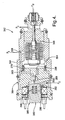
- Figure 2 is a cross sectional view of a first embodiment of the electronic control valve of the compressor assembly;
- Figure 3 is a cross sectional view of a second embodiment of the electronic control valve; and
- Figure 4 is a cross sectional view of a third embodiment of the electronic control valve.
- Referring to the Figures, wherein like numerals indicate corresponding parts throughout the several views, a compressor assembly is shown in Figure 1 generally at 20.
- The
compressor assembly 20 is of the variable angle wobble plate type for use in an air conditioning system of a motor vehicle. Thecompressor assembly 20 includes a compressor housing 22 defining asuction cavity 24 for receiving a fluid (refrigerant) at a suction pressure, adischarge cavity 26 for receiving the fluid from thesuction cavity 24 at a discharge pressure higher than the suction pressure, and acrankcase 28 in fluid communication with thedischarge cavity 26. The air conditioning system includes anormal condenser 30, anorifice tube 32, anevaporator 34, and anaccumulator 36, arranged in that order between thedischarge cavity 26 and thesuction cavity 24 respectively. Thecrankcase 28 encloses a variableangle wobble plate 38 and at least onecompressor piston 40 having a variable piston stroke. - The variable stroke of the compressor pistons 40 (only two being shown), and thereby the displacement of the
compressor assembly 20, is determined by the operating angle of the compressor's variableangle wobble plate 38. Thewobble plate 38 is made to angulate by pressurizing the sealedcrankcase 28 with the fluid from thedischarge cavity 26 at the discharge pressure, and controlling the fluid pressure in thecrankcase 28 relative to the suction pressure. Acontrol valve 42 is disposed in the compressor housing 22 and is responsive to the suction pressure to increase the variable piston stroke, and thereby the displacement of thecompressor assembly 20 with an increase in the suction pressure of the fluid from thesuction cavity 24. - Referring to Figures 2 and 3, the control valve is generally shown at 42, and includes a
valve casing 44, which defines achamber 46 therein. Amember 48 is moveable in thechamber 46 between an activated position and a neutral position. Themember 48 may be a bellows, a diaphragm aneroid, or any other internal suction pressure sensing element known to those skilled in the art. The activated position opens fluid communication between thedischarge cavity 26 and thecrankcase 28, while closing fluid communication between thesuction cavity 24 and thecrankcase 28. The activated position is for pressurizing thecrankcase 28 with the fluid at the discharge pressure to decrease the piston stroke. The neutral position closes fluid communication between thedischarge cavity 26 and thecrankcase 28, while opening fluid communication between thesuction cavity 24 and thecrankcase 28 for pressurizing thecrankcase 28 with the fluid at the suction pressure to increase the piston stroke. - During normal operation, the fluid leaving the
accumulator 36 at the suction pressure enters thesuction cavity 24 of thecompressor assembly 20 and is discharged to thedischarge cavity 26 of thecompressor assembly 20 at the discharge pressure, and thence to the condenser at a certain rate, which is dependent upon the angle of thewobble plate 38. At the same time, the fluid from thesuction cavity 24 at the suction pressure is transmitted to thecontrol valve 42 to act on themember 48, which tends to expand in response to a decrease in the suction pressure once the suction pressure falls below a pre-determined set-point. Themember 48 provides a force to anoutput rod 50, which opens acrankcase charge port 52 by lifting aball valve 54. Thecrankcase charge port 52, when open, communicates the fluid at the discharge pressure in thedischarge cavity 26 with thecrankcase 28 via acrankcase port 56. - The fluid from the
discharge cavity 26 at the discharge pressure acts on theball valve 54 in opposition to themember 48 to urge theball valve 54 and themember 48 into the neutral position when the suction pressure of the fluid from thesuction cavity 24 is above the pre-determined set-point. The pressure biases between the suction pressure and the discharge pressure are in addition to a spring bias from themember 48, which act to normally condition themember 48 in the neutral position to thereby normally effect maximum compressor displacement by establishing a zerocrankcase 28 suction pressure differential. - The
valve casing 44 includes a cylindricalcentral portion 58 having a closedend 60. Thecentral portion 58 of thevalve casing 44 defines thechamber 46 therein. Themember 48 is disposed within thechamber 46 defined by thecentral portion 58 of thevalve casing 44. The closedend 60 of thecentral portion 58 of thevalve casing 44 defines anactuator port 62 in fluid communication with thedischarge cavity 26. Theactuator port 62 includes a diameter (dap) sufficient in size to provide the fluid flow at the discharge pressure to thechamber 46. The fluid flow at the discharge pressure urges themember 48 into the activated position. - The
control valve 42 includes a control mechanism generally indicated at 64, for opening theactuator port 62 to allow fluid communication between thedischarge cavity 26 and thechamber 46 and closing theactuator port 62 to prevent fluid communication between thedischarge cavity 26 and thechamber 46. Thevalve casing 44 includes asuction port 68 in fluid communication with thesuction cavity 24 for providing the fluid flow at the suction pressure form thesuction cavity 24 to thechamber 46. As described in each of the embodiments, thecontrol mechanism 64 includes a solenoid generally indicated at 66, for opening and closing theactuator port 62 to controll the fluid flow into thechamber 46. - In a first and a second embodiment of the subject invention as shown in Figures 2 and 3 respectively, a
piston 70 is disposed in thechamber 46 between theactuator port 62 and thesuction port 68, bisecting thechamber 46 into adischarge pressure side 72 and asuction pressure side 74. Thedischarge pressure side 72 of thechamber 46 receives the fluid flow from thedischarge cavity 26 at the discharge pressure through theactuator port 62. Thesuction pressure side 74 of thechamber 46 receives the fluid flow from thesuction cavity 24 at the suction pressure through thesuction port 68. Thecontrol valve 42 includes aspring 76 for biasing thepiston 70 into the neutral position within thechamber 46 when thecontrol mechanism 64 closes theactuator port 62. Thespring 76 is disposed within thesuction pressure side 74 of thechamber 46, biasing thepiston 70 towards theclosed end 60 of thecentral portion 58 of thevalve casing 44. Themember 48 is disposed in thesuction pressure side 74 of thechamber 46 and is responsive to the fluid flow at the suction pressure from thesuction cavity 24 for moving themember 48 into the activated position when the suction pressure is below the pre-determined set-point. - The
piston 70 includes ableeder port 78 interconnecting thedischarge pressure side 72 of thechamber 46 and thesuction pressure side 74 of thechamber 46. Thebleeder port 78 equalizes the pressure differential between the fluid at the discharge pressure in thedischarge pressure side 72 of thechamber 46 and the fluid at the suction pressure in thesuction pressure side 74 of thechamber 46. Thebleeder port 78 includes a diameter (dbp) less then the diameter of theactuator port 62, so that when thecontrol mechanism 64 opens fluid communication between thedischarge cavity 26 and thechamber 46, fluid will flow through theactuator port 62 faster than the fluid will flow through thebleeder port 78. - In the First embodiment of the
control valve 42, as shown in Figure 2, thesolenoid 66 is activated by an electrical current to close theactuator port 62. In the absence of an electrical current, theactuator port 62 is open, and the fluid from thedischarge cavity 26 at the discharge pressure flows into thechamber 46 to de-stroke thecompressor assembly 20. Thesolenoid 66 includes apole piece 80 adjacent theclosed end 60 of thecentral portion 58 of thevalve casing 44. Anarmature 82 is disposed next to thepole piece 80 and moveable toward thepole piece 80 in the presence of the electric current. Acoil 84 is wrapped around abobbin 86, which surrounds thearmature 82 andpole piece 80. Ashaft 88 extends from thearmature 82, though thepole piece 80 and includes a sealing end 90 for abutting against theactuator port 62. The electric current passes through thecoil 84 and produces a magnetic field, which draws thearmature 82 and theshaft 88 toward thepole piece 80, thereby bringing the sealing end 90 of theshaft 88 into sealing engagement with theactuator port 62 to close fluid communication between thedischarge cavity 26 and thechamber 46. - Accordingly, when the
solenoid 66 is configured as described in the First embodiment, thecompressor assembly 20 does not require the use of a drive clutch (not shown) to disengage thecompressor assembly 20 during certain operating conditions. When an occupant of the vehicle signals to activate the air conditioning system, the electric current flows to thesolenoid 66, which closes theactuator port 62 so that thecompressor assembly 20 operates at capacity. When the air conditioning system is disengaged, the electric current to thesolenoid 66 is disrupted, and theactuator port 62 is opened to allow fluid communication between thedischarge cavity 26 at the discharge pressure into thechamber 46 to urge themember 48 into the activated position to de-stroke thecompressor assembly 20. Therefore, no clutch is necessary, which reduces the weight and cost of thecompressor assembly 20. - Elements of a second embodiment, which are similar to the elements of the first embodiment, are indicated by the same numeral used in the first embodiment preceded by the number two. As shown in Figure 3, the
solenoid 266 is activated by an electrical current to open theactuator port 262. In the absence of the electrical current, theactuator port 262 is closed, preventing the fluid from thedischarge cavity 26 from entering thechamber 246. Thesolenoid 266 includes anarmature 282 adjacent theclosed end 260 of thecentral portion 258 of thevalve casing 244. Apole piece 280 is disposed next to thearmature 282. Acoil 284 is wrapped around abobbin 286, which surrounds thearmature 282 and thepole piece 280. Thearmature 282 includes a sealingportion 292 for abutting theactuator port 262, and is moveable away from theactuator port 262 in the presence of the electrical current. The electric current passes through thecoil 284, producing a magnetic field, which draws thearmature 282 toward thepole piece 280 and away from theactuator port 262 so that the sealingportion 292 of thearmature 282 is not in sealing engagement with theactuator port 262. Thus, fluid communication is opened between thedischarge cavity 26 and thechamber 246. - Accordingly, the
control valve 242 described in the second embodiment includes a second set-point that de-strokes thecompressor assembly 20, instead of disengaging a drive clutch (not shown). The first and second set-points can be any two modes chosen from a group including: a rapid cool down mode, which permits intermittent operation below an evaporator temperature of 0°C; a normal pneumatic mode, which permits operation at an evaporator temperature just above 0°C; a fuel economy mode, which permits operation at an evaporator temperature of approximately 10°C; and a full de-stroke mode. - Elements of a third embodiment, which are similar to the elements of the first embodiment, are indicated by the same numeral used in the first embodiment preceded by the number three. As shown in Figure 4, the
control valve 342 includes anexpandable device 394 in fluid communication with theactuator port 362. Thevalve casing 344 includes acontrol chamber 398 in fluid communication with theactuator port 362 and thesuction port 368. A bleeder port 378 interconnects thecontrol chamber 398 to theexpandable device 394. Theexpandable device 394 is disposed between thecontrol chamber 398 and themember 348 for expanding in response to the fluid flow at the discharge pressure from thedischarge cavity 26 and urging theexpandable device 394 and themember 348 into the activated position. - The
solenoid 366 of the third embodiment of thecontrol valve 342 is activated by an electrical current to close the actuator port. In the absence of an electrical current, theactuator port 362 is open, and the fluid from thedischarge cavity 26 at the discharge pressure flows into thecontrol chamber 398. Simultaneously, in the absence of an electrical current, thesolenoid 366 closes fluid communication between thecontrol chamber 398 and thesuction pressure port 368. Accordingly, in the absence of an electrical current, the fluid flow from thedischarge cavity 26 at the discharge pressure flows into the expandable device through adeactivation port 396 to expand the expandable device and urge themember 348 into the activated position. When an electrical current is present, thesolenoid 366 closes the actuator port and opens fluid communication between thecontrol chamber 398 and thesuction pressure port 368. Accordingly, when an electrical current is present, the fluid flow from thesuction cavity 24 at the suction pressure draws theexpandable device 394 back to the neutral position. While thecontrol valve 342 of the third embodiment is shown with a piston 370, it is contemplated that a piston could be disposed between theexpandable device 394 and themember 348. Accordingly, the scope of the third embodiment of thecontrol valve 342 should not be so limited. - The foregoing invention has been described in accordance with the relevant legal standards; thus, the description is exemplary rather than limiting in nature. Variations and modifications to the disclosed embodiment may become apparent to those skilled in the art and do come within the scope of the invention. Accordingly, the scope of legal protection afforded this invention can only be determined by studying the following claims.
Claims (12)
- A compressor assembly (20) for a climate control system of a vehicle, said assembly (20) comprising;a compressor housing (22) defining a suction cavity (24) for receiving a fluid at a suction pressure and a discharge cavity (26) for receiving the fluid from said suction cavity (24) at a discharge pressure higher than the suction pressure and a crankcase (28) in fluid communication with said discharge cavity (26) and enclosing a variable angle wobble plate (38) and at least one compressor piston (40) having a variable piston stroke,a valve casing (44) disposed in said compressor housing (22) and defining a chamber (46) therein,a member (48) moveable in said chamber (46) between an activated position opening fluid communication between said discharge cavity (26) and said crankcase (28) while closing fluid communication between said suction cavity (24) and said crankcase (28) for pressurizing said crankcase (28) with the fluid at the discharge pressure to decrease said piston stroke and a neutral position closing fluid communication between said discharge cavity (26) and said crankcase (28) while opening fluid communication between said suction cavity (24) and said crankcase (28) for pressurizing said crankcase (28) with the fluid at the suction pressure to increase said piston stroke,said valve casing (44) including an actuator port (62) in fluid communication with said discharge cavity (26) for providing the fluid flow at the discharge pressure to said chamber (46) for urging said member (48) into said activated position in response to the fluid flow at the discharge pressure.
- An assembly (20) as set forth in claim 1 including a control mechanism (64) for opening said actuator port (62) to allow fluid communication between said discharge cavity (26) and said chamber (46) and closing said actuator port (62) to prevent fluid communication between said discharge cavity (26) and said chamber (46).
- An assembly (20) as set forth in claim 2 including a suction port (68) in fluid communication with said suction cavity (24) for providing the fluid flow at the suction pressure form said suction cavity (24) to said chamber (46), and a piston (70) disposed in said chamber (46) between said actuator port (62) and said suction port (68) for bisecting said chamber (46) into a discharge pressure side (72) and a suction pressure side (74) with said discharge pressure side (72) of said chamber (46) receiving the fluid flow from said discharge cavity (26) at the discharge pressure through said actuator port (62) and said suction pressure side (74) of said chamber (46) receiving the fluid flow from said suction cavity (24) at the suction pressure through said suction port (68).
- An assembly (20) as set forth in claim 3 including a spring (76) for biasing said piston (70) into said neutral position within said chamber (46) in response to said control mechanism (64) closing said actuator port (62).
- An assembly (20) as set forth in claim 4 wherein said member (48) is disposed in said suction pressure side (74) of said chamber (46) and is responsive to the fluid flow at the suction pressure from said suction cavity (24) for moving said member (48) into said activated position when the suction pressure is below a pre-determined set-point.
- An assembly (20) as set forth in claim 5 wherein said piston (70) includes a bleeder port (78) interconnecting said discharge pressure side (72) of said chamber (46) and said suction pressure side (74) of said chamber (46) for equalizing the pressure differential between the fluid at the discharge pressure in the discharge pressure side (72) and the fluid at the suction pressure in the suction pressure side (74) of said chamber (46).
- An assembly (20) as set forth in claim 6 wherein said actuator port (62) includes a diameter (dap) and said bleeder port (78) includes a diameter (dbp) less then said diameter of said actuator port (62).
- An assembly (20) as set forth in claim 7 wherein said control mechanism (64) includes a solenoid (66) for opening and closing said actuator port (62) for controlling the fluid flow into said discharge chamber (46).
- An assembly (20) as set forth in claim 8 wherein said solenoid (66) is activated by an electrical current to open said actuator port (62).
- An assembly (20) as set forth in claim 8 wherein said solenoid (66) is activated by an electrical current to close said actuator port (62).
- An assembly (20) as set forth in claim 2 including an expandable device (394) in fluid communication with said actuator port (62) and disposed between said actuator port (62) and said piston (70) within said discharge pressure side (72) of said chamber (46) for expanding in response to the fluid flow at the discharge pressure from said discharge cavity (26) and urging said piston (70) and said member (48) into said activated position.
- An assembly (20) as set forth in claim 11 wherein said expandable device (394) includes a deactivation port (396) in fluid communication with said suction cavity (24) and controlled by said control mechanism (64) and said activated position includes opening said actuator port (62) and closing said deactivation port (396) for allowing fluid communication between said discharge cavity (26) and said expandable device (394) and said neutral position includes closing said actuator port (62) and opening said deactivation port (396) for allowing fluid communication between said suction cavity (24) and said expandable device (394).
Applications Claiming Priority (1)
| Application Number | Priority Date | Filing Date | Title |
|---|---|---|---|
| US11/375,999 US7611335B2 (en) | 2006-03-15 | 2006-03-15 | Two set-point pilot piston control valve |
Publications (2)
| Publication Number | Publication Date |
|---|---|
| EP1835176A2 true EP1835176A2 (en) | 2007-09-19 |
| EP1835176A3 EP1835176A3 (en) | 2008-09-10 |
Family
ID=38093502
Family Applications (1)
| Application Number | Title | Priority Date | Filing Date |
|---|---|---|---|
| EP07075140A Withdrawn EP1835176A3 (en) | 2006-03-15 | 2007-02-19 | Two-set point pilot piston control valve |
Country Status (2)
| Country | Link |
|---|---|
| US (1) | US7611335B2 (en) |
| EP (1) | EP1835176A3 (en) |
Families Citing this family (4)
| Publication number | Priority date | Publication date | Assignee | Title |
|---|---|---|---|---|
| JP6091503B2 (en) * | 2012-05-24 | 2017-03-08 | イーグル工業株式会社 | Capacity control valve |
| US12152576B2 (en) | 2017-02-17 | 2024-11-26 | Hanon Systems | Swash plate compressor |
| KR102436353B1 (en) | 2017-02-17 | 2022-08-25 | 한온시스템 주식회사 | Swash plate type compressure |
| KR102692484B1 (en) * | 2019-05-20 | 2024-08-07 | 현대자동차주식회사 | Hvac system for vehicle, electronic control valve for the hvac system and controlling method for the hvac system |
Citations (2)
| Publication number | Priority date | Publication date | Assignee | Title |
|---|---|---|---|---|
| US4606705A (en) | 1985-08-02 | 1986-08-19 | General Motors Corporation | Variable displacement compressor control valve arrangement |
| US20050287014A1 (en) | 2004-06-28 | 2005-12-29 | Kabushiki Kaisha Toyota Jidoshokki | Displacement control valve for variable displacement compressor |
Family Cites Families (56)
| Publication number | Priority date | Publication date | Assignee | Title |
|---|---|---|---|---|
| US4526516A (en) | 1983-02-17 | 1985-07-02 | Diesel Kiki Co., Ltd. | Variable capacity wobble plate compressor capable of controlling angularity of wobble plate with high responsiveness |
| US5451146A (en) | 1992-04-01 | 1995-09-19 | Nippondenso Co., Ltd. | Scroll-type variable-capacity compressor with bypass valve |
| JP3178631B2 (en) | 1993-01-11 | 2001-06-25 | 株式会社豊田自動織機製作所 | Control valve for variable displacement compressor |
| JP3355002B2 (en) | 1993-10-15 | 2002-12-09 | 株式会社豊田自動織機 | Control valve for variable displacement compressor |
| JP3417067B2 (en) | 1994-07-29 | 2003-06-16 | 株式会社豊田自動織機 | Variable displacement compressor |
| JP3175536B2 (en) | 1995-06-13 | 2001-06-11 | 株式会社豊田自動織機製作所 | Capacity control structure for clutchless variable displacement compressor |
| KR100203975B1 (en) | 1995-10-26 | 1999-06-15 | 이소가이 치세이 | Cam Plate Variable Capacity Compressor |
| US5702235A (en) * | 1995-10-31 | 1997-12-30 | Tgk Company, Ltd. | Capacity control device for valiable-capacity compressor |
| JP3858297B2 (en) | 1996-01-25 | 2006-12-13 | 株式会社デンソー | Pressure control valve and vapor compression refrigeration cycle |
| JPH102284A (en) | 1996-06-17 | 1998-01-06 | Toyota Autom Loom Works Ltd | Variable displacement compressor and control method thereof |
| JPH10196540A (en) | 1997-01-10 | 1998-07-31 | Toyota Autom Loom Works Ltd | Compressor |
| JP3585150B2 (en) * | 1997-01-21 | 2004-11-04 | 株式会社豊田自動織機 | Control valve for variable displacement compressor |
| JP3789023B2 (en) | 1997-05-14 | 2006-06-21 | 株式会社豊田自動織機 | Solenoid control valve |
| JPH10325393A (en) | 1997-05-26 | 1998-12-08 | Zexel Corp | Variable displacement swash plate type clutchless compressor |
| JP3890713B2 (en) | 1997-11-27 | 2007-03-07 | 株式会社デンソー | Refrigeration cycle equipment |
| JP4160669B2 (en) * | 1997-11-28 | 2008-10-01 | 株式会社不二工機 | Control valve for variable displacement compressor |
| JP4000694B2 (en) | 1997-12-26 | 2007-10-31 | 株式会社豊田自動織機 | Capacity control valve in variable capacity compressor |
| JP4149558B2 (en) | 1998-03-27 | 2008-09-10 | サンデン株式会社 | Volume control valve for variable capacity compressor |
| JP3783434B2 (en) | 1998-04-13 | 2006-06-07 | 株式会社豊田自動織機 | Variable capacity swash plate compressor and air conditioning cooling circuit |
| JP3900669B2 (en) | 1998-04-16 | 2007-04-04 | 株式会社豊田自動織機 | Control valve and variable displacement compressor |
| JPH11336660A (en) | 1998-05-27 | 1999-12-07 | Toyota Autom Loom Works Ltd | Variable displacement compressor and method of assembling the same |
| JP2000064957A (en) | 1998-08-17 | 2000-03-03 | Toyota Autom Loom Works Ltd | Variable displacement swash plate compressor and extraction side control valve |
| JP3984724B2 (en) | 1998-09-10 | 2007-10-03 | 株式会社豊田自動織機 | Control valve for variable capacity swash plate compressor and swash plate compressor |
| JP2000320464A (en) | 1999-05-10 | 2000-11-21 | Saginomiya Seisakusho Inc | Control valve for variable displacement compressor |
| US6182457B1 (en) | 1999-06-02 | 2001-02-06 | Ranco Incorporated Of Delaware | Electronic variable orifice tube and system for use therewith |
| JP2001021230A (en) | 1999-07-12 | 2001-01-26 | Tgk Co Ltd | Expansion valve of refrigeration cycle using variable displacement compressor |
| JP3911937B2 (en) | 1999-08-04 | 2007-05-09 | 株式会社豊田自動織機 | Control method for air conditioner and variable capacity compressor |
| JP2001073939A (en) | 1999-08-31 | 2001-03-21 | Toyota Autom Loom Works Ltd | Control valve of variable displacement compressor and variable displacement compressor |
| JP3991556B2 (en) | 1999-10-04 | 2007-10-17 | 株式会社豊田自動織機 | Control valve for variable capacity compressor |
| JP2001133053A (en) | 1999-11-01 | 2001-05-18 | Toyota Autom Loom Works Ltd | Air conditioner |
| JP3941303B2 (en) | 1999-11-17 | 2007-07-04 | 株式会社豊田自動織機 | Air conditioner |
| JP3780784B2 (en) | 1999-11-25 | 2006-05-31 | 株式会社豊田自動織機 | Control valve for air conditioner and variable capacity compressor |
| JP2001221158A (en) | 1999-11-30 | 2001-08-17 | Toyota Autom Loom Works Ltd | Control valve for variable displacement compressor |
| JP2001165055A (en) | 1999-12-09 | 2001-06-19 | Toyota Autom Loom Works Ltd | Control valve and variable displacement compressor |
| US6364627B1 (en) | 1999-12-23 | 2002-04-02 | Visteon Global Technologies, Inc. | Control valve means in an external conduit of a variable displacement swash plate type compressor |
| JP3799921B2 (en) | 1999-12-24 | 2006-07-19 | 株式会社豊田自動織機 | Control device for variable capacity compressor |
| JP2001193662A (en) | 2000-01-07 | 2001-07-17 | Toyota Autom Loom Works Ltd | Control device for variable displacement compressor |
| JP2001221157A (en) | 2000-02-04 | 2001-08-17 | Toyota Autom Loom Works Ltd | Variable capacity compressor |
| JP3797055B2 (en) | 2000-02-07 | 2006-07-12 | 株式会社豊田自動織機 | Control unit for variable capacity compressor |
| JP4221893B2 (en) | 2000-02-28 | 2009-02-12 | 株式会社豊田自動織機 | Capacity control device and compressor module for variable capacity compressor |
| JP3731434B2 (en) | 2000-03-30 | 2006-01-05 | 株式会社豊田自動織機 | Control valve for variable capacity compressor |
| JP3917347B2 (en) | 2000-05-18 | 2007-05-23 | 株式会社豊田自動織機 | Air conditioner for vehicles |
| DE10125009A1 (en) | 2000-05-24 | 2001-12-06 | Sanden Corp | Adjustable swash plate compressor with capacity control mechanisms |
| JP2001349624A (en) | 2000-06-08 | 2001-12-21 | Toyota Industries Corp | Capacity control valve for air conditioner and variable capacity compressor |
| JP2002013474A (en) | 2000-06-28 | 2002-01-18 | Toyota Industries Corp | Variable capacity compressor |
| JP2002054561A (en) | 2000-08-08 | 2002-02-20 | Toyota Industries Corp | Control valve of variable displacement compressor and variable displacement compressor |
| JP2002147351A (en) * | 2000-11-10 | 2002-05-22 | Toyota Industries Corp | Control device for variable displacement compressor |
| JP4333042B2 (en) | 2001-02-20 | 2009-09-16 | 株式会社豊田自動織機 | Control valve for variable capacity compressor |
| JP3925091B2 (en) | 2001-02-28 | 2007-06-06 | 株式会社豊田自動織機 | Control valve for variable capacity compressor and method for adjusting the control valve |
| US6746214B2 (en) | 2001-03-01 | 2004-06-08 | Pacific Industrial Co., Ltd. | Control valve for compressors and manufacturing method thereof |
| US6663358B2 (en) | 2001-06-11 | 2003-12-16 | Bristol Compressors, Inc. | Compressors for providing automatic capacity modulation and heat exchanging system including the same |
| JP3943871B2 (en) | 2001-07-25 | 2007-07-11 | 株式会社テージーケー | Variable capacity compressor and capacity control valve for variable capacity compressor |
| JP3726759B2 (en) | 2002-02-18 | 2005-12-14 | 株式会社豊田自動織機 | Control device for variable capacity compressor |
| GB0214467D0 (en) | 2002-06-24 | 2002-08-07 | Delphi Tech Inc | Control valve for air conditioning compressor |
| KR100466620B1 (en) | 2002-07-09 | 2005-01-15 | 삼성전자주식회사 | Variable capacity rotary compressor |
| US6799952B2 (en) | 2002-09-05 | 2004-10-05 | Delphi Technologies, Inc. | Pneumatically operated compressor capacity control valve with discharge pressure sensor |
-
2006
- 2006-03-15 US US11/375,999 patent/US7611335B2/en not_active Expired - Fee Related
-
2007
- 2007-02-19 EP EP07075140A patent/EP1835176A3/en not_active Withdrawn
Patent Citations (2)
| Publication number | Priority date | Publication date | Assignee | Title |
|---|---|---|---|---|
| US4606705A (en) | 1985-08-02 | 1986-08-19 | General Motors Corporation | Variable displacement compressor control valve arrangement |
| US20050287014A1 (en) | 2004-06-28 | 2005-12-29 | Kabushiki Kaisha Toyota Jidoshokki | Displacement control valve for variable displacement compressor |
Also Published As
| Publication number | Publication date |
|---|---|
| US20070217923A1 (en) | 2007-09-20 |
| US7611335B2 (en) | 2009-11-03 |
| EP1835176A3 (en) | 2008-09-10 |
Similar Documents
| Publication | Publication Date | Title |
|---|---|---|
| JP6149239B2 (en) | Control valve for variable capacity compressor | |
| EP1052463B1 (en) | Expansion valve | |
| US6453685B2 (en) | Control apparatus and control method for variable displacement compressor | |
| US6526771B2 (en) | Freezing cycle apparatus | |
| KR102057344B1 (en) | Control valve for variable displacement compressor | |
| KR20180111741A (en) | Control valve for variable displacement compressor | |
| EP2573438A1 (en) | Pilot operated solenoid valve | |
| JP2018040385A (en) | solenoid valve | |
| EP1039129A2 (en) | Device and method for controlling displacement of variable displacement compressor | |
| US7036744B2 (en) | Solenoid valve-equipped expansion valve | |
| JP3555592B2 (en) | Refrigeration cycle device and valve device used therefor | |
| JP6085789B2 (en) | Control valve for variable capacity compressor | |
| EP3239520B1 (en) | Control valve for variable displacement compressor | |
| US7014427B1 (en) | Capacity controller of capacity variable compressor | |
| WO2007111040A1 (en) | Control valve for variable displacement compressor | |
| US7611335B2 (en) | Two set-point pilot piston control valve | |
| EP1155888A2 (en) | Air conditioner | |
| US4129995A (en) | Evaporation pressure control device | |
| JPH0914797A (en) | Expansion valve integrated with solenoid valve | |
| JP4173018B2 (en) | Capacity control valve for variable capacity compressor | |
| JP6064182B2 (en) | Control valve for variable capacity compressor | |
| JP5519199B2 (en) | Variable capacity swash plate compressor and air conditioning system using the same | |
| KR20140141432A (en) | Control valve for variable displacement compressor | |
| JP2020101242A (en) | Control valve | |
| JP2017137797A (en) | Control valve for variable capacity compressor |
Legal Events
| Date | Code | Title | Description |
|---|---|---|---|
| PUAI | Public reference made under article 153(3) epc to a published international application that has entered the european phase |
Free format text: ORIGINAL CODE: 0009012 |
|
| AK | Designated contracting states |
Kind code of ref document: A2 Designated state(s): AT BE BG CH CY CZ DE DK EE ES FI FR GB GR HU IE IS IT LI LT LU LV MC NL PL PT RO SE SI SK TR |
|
| AX | Request for extension of the european patent |
Extension state: AL BA HR MK YU |
|
| PUAL | Search report despatched |
Free format text: ORIGINAL CODE: 0009013 |
|
| AK | Designated contracting states |
Kind code of ref document: A3 Designated state(s): AT BE BG CH CY CZ DE DK EE ES FI FR GB GR HU IE IS IT LI LT LU LV MC NL PL PT RO SE SI SK TR |
|
| AX | Request for extension of the european patent |
Extension state: AL BA HR MK RS |
|
| 17P | Request for examination filed |
Effective date: 20090310 |
|
| 17Q | First examination report despatched |
Effective date: 20090408 |
|
| AKX | Designation fees paid |
Designated state(s): AT BE BG CH CY CZ DE DK EE ES FI FR GB GR HU IE IS IT LI LT LU LV MC NL PL PT RO SE SI SK TR |
|
| STAA | Information on the status of an ep patent application or granted ep patent |
Free format text: STATUS: THE APPLICATION IS DEEMED TO BE WITHDRAWN |
|
| 18D | Application deemed to be withdrawn |
Effective date: 20100901 |