EP1834697A2 - Multi-cyclone contaminants collector for vacuum cleaner - Google Patents
Multi-cyclone contaminants collector for vacuum cleaner Download PDFInfo
- Publication number
- EP1834697A2 EP1834697A2 EP06291180A EP06291180A EP1834697A2 EP 1834697 A2 EP1834697 A2 EP 1834697A2 EP 06291180 A EP06291180 A EP 06291180A EP 06291180 A EP06291180 A EP 06291180A EP 1834697 A2 EP1834697 A2 EP 1834697A2
- Authority
- EP
- European Patent Office
- Prior art keywords
- contaminants
- cyclone
- cyclones
- collector
- chambers
- Prior art date
- Legal status (The legal status is an assumption and is not a legal conclusion. Google has not performed a legal analysis and makes no representation as to the accuracy of the status listed.)
- Withdrawn
Links
Images


Classifications
-
- B—PERFORMING OPERATIONS; TRANSPORTING
- B01—PHYSICAL OR CHEMICAL PROCESSES OR APPARATUS IN GENERAL
- B01D—SEPARATION
- B01D21/00—Separation of suspended solid particles from liquids by sedimentation
- B01D21/24—Feed or discharge mechanisms for settling tanks
- B01D21/245—Discharge mechanisms for the sediments
- B01D21/2472—Means for fluidising the sediments, e.g. by jets or mechanical agitators
-
- B—PERFORMING OPERATIONS; TRANSPORTING
- B04—CENTRIFUGAL APPARATUS OR MACHINES FOR CARRYING-OUT PHYSICAL OR CHEMICAL PROCESSES
- B04C—APPARATUS USING FREE VORTEX FLOW, e.g. CYCLONES
- B04C5/00—Apparatus in which the axial direction of the vortex is reversed
- B04C5/14—Construction of the underflow ducting; Apex constructions; Discharge arrangements ; discharge through sidewall provided with a few slits or perforations
- B04C5/185—Dust collectors
-
- A—HUMAN NECESSITIES
- A47—FURNITURE; DOMESTIC ARTICLES OR APPLIANCES; COFFEE MILLS; SPICE MILLS; SUCTION CLEANERS IN GENERAL
- A47L—DOMESTIC WASHING OR CLEANING; SUCTION CLEANERS IN GENERAL
- A47L9/00—Details or accessories of suction cleaners, e.g. mechanical means for controlling the suction or for effecting pulsating action; Storing devices specially adapted to suction cleaners or parts thereof; Carrying-vehicles specially adapted for suction cleaners
- A47L9/10—Filters; Dust separators; Dust removal; Automatic exchange of filters
- A47L9/16—Arrangement or disposition of cyclones or other devices with centrifugal action
- A47L9/1608—Cyclonic chamber constructions
-
- A—HUMAN NECESSITIES
- A47—FURNITURE; DOMESTIC ARTICLES OR APPLIANCES; COFFEE MILLS; SPICE MILLS; SUCTION CLEANERS IN GENERAL
- A47L—DOMESTIC WASHING OR CLEANING; SUCTION CLEANERS IN GENERAL
- A47L9/00—Details or accessories of suction cleaners, e.g. mechanical means for controlling the suction or for effecting pulsating action; Storing devices specially adapted to suction cleaners or parts thereof; Carrying-vehicles specially adapted for suction cleaners
- A47L9/10—Filters; Dust separators; Dust removal; Automatic exchange of filters
- A47L9/16—Arrangement or disposition of cyclones or other devices with centrifugal action
- A47L9/1616—Multiple arrangement thereof
-
- A—HUMAN NECESSITIES
- A47—FURNITURE; DOMESTIC ARTICLES OR APPLIANCES; COFFEE MILLS; SPICE MILLS; SUCTION CLEANERS IN GENERAL
- A47L—DOMESTIC WASHING OR CLEANING; SUCTION CLEANERS IN GENERAL
- A47L9/00—Details or accessories of suction cleaners, e.g. mechanical means for controlling the suction or for effecting pulsating action; Storing devices specially adapted to suction cleaners or parts thereof; Carrying-vehicles specially adapted for suction cleaners
- A47L9/10—Filters; Dust separators; Dust removal; Automatic exchange of filters
- A47L9/16—Arrangement or disposition of cyclones or other devices with centrifugal action
- A47L9/1683—Dust collecting chambers; Dust collecting receptacles
-
- B—PERFORMING OPERATIONS; TRANSPORTING
- B04—CENTRIFUGAL APPARATUS OR MACHINES FOR CARRYING-OUT PHYSICAL OR CHEMICAL PROCESSES
- B04C—APPARATUS USING FREE VORTEX FLOW, e.g. CYCLONES
- B04C5/00—Apparatus in which the axial direction of the vortex is reversed
- B04C5/24—Multiple arrangement thereof
- B04C5/26—Multiple arrangement thereof for series flow
-
- B—PERFORMING OPERATIONS; TRANSPORTING
- B04—CENTRIFUGAL APPARATUS OR MACHINES FOR CARRYING-OUT PHYSICAL OR CHEMICAL PROCESSES
- B04C—APPARATUS USING FREE VORTEX FLOW, e.g. CYCLONES
- B04C5/00—Apparatus in which the axial direction of the vortex is reversed
- B04C5/24—Multiple arrangement thereof
- B04C5/28—Multiple arrangement thereof for parallel flow
-
- C—CHEMISTRY; METALLURGY
- C02—TREATMENT OF WATER, WASTE WATER, SEWAGE, OR SLUDGE
- C02F—TREATMENT OF WATER, WASTE WATER, SEWAGE, OR SLUDGE
- C02F1/00—Treatment of water, waste water, or sewage
- C02F1/52—Treatment of water, waste water, or sewage by flocculation or precipitation of suspended impurities
-
- E—FIXED CONSTRUCTIONS
- E03—WATER SUPPLY; SEWERAGE
- E03F—SEWERS; CESSPOOLS
- E03F11/00—Cesspools
-
- C—CHEMISTRY; METALLURGY
- C02—TREATMENT OF WATER, WASTE WATER, SEWAGE, OR SLUDGE
- C02F—TREATMENT OF WATER, WASTE WATER, SEWAGE, OR SLUDGE
- C02F2303/00—Specific treatment goals
- C02F2303/22—Eliminating or preventing deposits, scale removal, scale prevention
Definitions
- the present invention relates to a vacuum cleaner. More particularly, the present invention relates to a multi-cyclone contaminants collector for a vacuum cleaner.
- a cyclone contaminants collector for a vacuum cleaner draws-in outside-air, forces the drawn-in outside-air to whirl, and separates and collects contaminants from the whirled outside-air by centrifugal force.
- the conventional cyclone contaminants collector includes a cyclone for whirling outside-air to centrifugally separate contaminants, and a contaminants chamber for collecting contaminants separated in the cyclone.
- a vacuum cleaner has currently been employed a multi-cyclone contaminants collector for increasing contaminant collecting efficiency.
- the multi-cyclone contaminants collector has a plurality of cyclones connected in series so as to remove contaminants from drawn-in outside-air in more than two steps.
- a conventional multi-cyclone contaminants collector for a vacuum cleaner includes a first cyclone for separating relatively large contaminants, and a second cyclone for separating fine contaminants.
- the second cyclone includes a plurality of cyclones.
- the conventional multi-cyclone contaminants collector furthermore includes a first contaminants chamber for collecting contaminants discharged from the first cyclone, and a second contaminants chamber for collecting fine contaminants discharged from the second cyclone. Therefore, the conventional multi-cyclone contaminants collector can effetely remove fine contaminants.
- the conventional multi-cyclone contaminants collector has only one second contaminants chamber to collect contaminants discharged from all the plurality of second cyclones, a whirling air current in any one of the plurality of second cyclones scatters contaminants collected in the second contaminants chamber thereby affecting whirling air currents in the other second cyclones.
- An aspect of the present invention is to provide a multi-cyclone contaminants collector for a vacuum cleaner preventing contaminants collected in a second contaminants chamber from flowing back into a second cyclone.
- the other aspect of the present invention is to provide a multi-cyclone contaminants collector for a vacuum cleaner preventing a whirling air current in any one of a plurality of second cyclones from scattering contaminants separated and collected by the other second cyclones.
- a multi-cyclone contaminants collector for a vacuum cleaner which includes at least one first cyclone drawing outside air so as to separate contaminants; at least one second cyclone separating fine contaminants from air discharged from the at least one first cyclone, the at least one second cyclone having a contaminants discharging opening for discharging the separated fine contaminants; and a dust cap disposed at the contaminants discharging opening, the dust cap preventing discharged fine contaminants from entering the second cyclone.
- the second cyclone has a diameter smaller than the first cyclone.
- the contaminants discharging opening is disposed at a top end of the second cyclone.
- the dust cap is disposed on a level with the contaminants discharging opening or to be projected from the contaminants discharging opening.
- the dust cap further comprises a dust guiding part.
- a multi-cyclone contaminants collector for a vacuum cleaner includes at least one first cyclone drawing outside air so as to separate contaminants; a plurality of second cyclones separating fine contaminants from air discharged from the at least one first cyclone, each of the plurality of second cyclones having a contaminants discharging opening for discharging the separated fine contaminants; a plurality of second contaminants chambers respectively wrapping around at least 2 second cyclones among the plurality of second cyclones, each of the plurality of second contaminants chambers collecting fine contaminants discharged from the wrapped second cyclones; and a partition wall partitioning each of the plurality of second contaminants chambers into spaces corresponding the at least 2 second cyclones to collect fine contaminants discharged from each of the at least 2 second cyclones.
- the plurality of second contaminants chambers is in contact with an outer circumferential surface of the first cyclone.
- each of the plurality of second contaminants chambers is spaced apart from next second contaminants chamber so that contaminants separated in the first cyclone are discharged through spaces between the plurality of second contaminants chambers.
- Each of the plurality of second cyclones further includes a dust cap disposed at the contaminants discharging opening to prevent fine contaminants collected in the second contaminants chamber from flowing back into the second cyclone.
- a lower portion of the at least 2 second cyclones wrapped around by the second contaminants chamber is projected out the second contaminants chamber.
- the multi-cyclone contaminants collector further includes a first contaminants chamber collecting contaminants discharged from the first cyclone, the first contaminants chamber wrapping around the first cyclone and the plurality of second contaminants chambers.
- a multi-cyclone contaminants collector for a vacuum cleaner includes: a first cyclone separating contaminants from outside air and discharging separated contaminants in a direction opposite to the gravity direction; a plurality of second cyclone separating fine contaminants from air discharged from the first cyclone, each of the second cyclones having a contaminants discharging opening for discharging separated fine contaminants in a direction opposite to the gravity direction; a plurality of second contaminants chambers respectively wrapping around at least 2 second cyclones among the plurality of second cyclones, each of the second contaminants chambers collecting fine contaminants discharged from the wrapped second cyclones; and a partition wall partitioning each of the plurality of second contaminants chambers into spaces corresponding to the at least 2 second cyclones to collect fine contaminants discharged from each of the at least 2 second cyclones.
- Each of the plurality of second contaminants chambers is spaced apart from next second contaminants chamber so that contaminants separated in the first cyclone are discharged through spaces between the plurality of second contaminants chambers
- the plurality of second contaminants chambers is in contact with an outer circumferential surface of the first cyclone.
- Each of the plurality of second cyclones further includes a dust cap disposed at the contaminants discharging opening to prevent fine contaminants collected in the second contaminants chamber from flowing back into the second cyclone. Also, the dust cap further includes a dust guiding part.
- Fig. 1 is an exploded perspective view illustrating a multi-cyclone contaminants collector for a vacuum cleaner according to an embodiment of the present invention
- Fig. 2 is a perspective view illustrating the multi-cyclone contaminants collector of Fig. 1 without an upper cover;
- Fig. 3 is a sectional view illustrating the multi-cyclone contaminants collector of Fig. 1;
- Fig. 4A is a top view illustrating another example of a dust cap of the multi-cyclone contaminants collector of Fig. 1;
- Fig. 4B is a sectional view of the dust cap of Fig. 4A;
- Fig. 5 is a plain view illustrating the multi-cyclone contaminants collector of Fig. 1 having another example of second contaminants chambers;
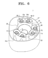
- Fig. 6 is a perspective view illustrating the multi-cyclone contaminants collector of Fig. 1 having another example of an outside receptacle
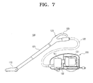
- Fig. 7 is a sectional view illustrating a vacuum cleaner having a multi-cyclone contaminants collector according to an embodiment of the present invention.
- a multi-cyclone contaminants collector 1 for a vacuum cleaner includes a first cyclone 10, a first contaminants chamber 30, a plurality of second cyclones 60, and a plurality of second contaminants chambers 70.
- the first cyclone 10 draws in outside-air containing contaminants such as dust, dirt and so on (hereinafter, referred to as contaminants-laden air), and then, forces contaminants-laden air to whirl so that contaminants are separated from the contaminants-laden air by centrifugal force operating upon the whirling contaminants-laden air.
- contaminants-laden air contaminants such as dust, dirt and so on
- the first cyclone 10 includes a first cyclone body 20, an air-communicating member 40, and an air suction pipe 11.
- the first cyclone body 20 is formed in a substantially hollow cylindrical shape with an opened top end and a closed bottom end. Contaminants-laden air is entered a lower portion of the first cyclone body 20 through the air suction pipe 11, and is whirled inside the first cyclone body 20 so as to form an upwardly whirling air current.
- contaminants are separated from the contaminants-laden air by centrifugal force operating upon the upwardly whirling air current, and discharged in a direction opposite to the gravity direction (an opposite direction of arrow K of Fig. 3).
- separated contaminants are discharged into the first contaminants chamber 30 over the top end of the first cyclone body 20 in the direction of arrow E of Fig. 3.
- the air-communicating member 40 discharges air (hereinafter, referred to as semi-clean air), which has contaminants removed from the contaminants-laden air in the first cyclone body 20 by centrifugal force, to each of the plurality of second cyclones 60. At this time, the semi-clean air contains fine contaminants having not been removed in the first cyclone 10.
- the air-communicating member 40 includes an air-communicating pipe 41 and a plurality of air guiding parts 42.
- the air-communicating pipe 41 is formed in a substantially hollow cylindrical shape, and projects from the center of a bottom surface 22 of the first cyclone body 20 into an inner space 23 of the first cyclone body 20.
- the air-communicating pipe 41 has opposite opened ends, and a top end of the air-communicating pipe 41 is spaced apart from an upper cover 80.
- the plurality of air guiding parts 42 is radially disposed based on the air-communicating pipe 41 under the bottom surface 22 of the first cyclone body 20.
- the bottom surface 22 of the first cyclone body 20, the plurality of air guiding parts 42, and a bottom surface 32 of an outside receptacle 31 form a plurality of air pathways 44.
- a bottom end of the air-communicating pipe 41 is in fluid communication with the plurality of air pathways 44.
- an air dispersing part 43 that disperses semi-clean air discharged from the air-communicating pipe 41 into each of the plurality of air pathways 44 is disposed in the center of the plurality of air guiding parts 42. Therefore, semi-clean air discharged through the air-communicating pipe 41 in the gravity direction (a direction of arrow K of Fig. 3) crashes against the air dispersing part 43, is scattered by the air dispersing part 43, and then, enters each of the plurality of second cyclones 60 through the plurality of air pathways 44.
- the plurality of air guiding parts 42 is integrally formed with the bottom surface 22 of the first cyclone body 20 as shown in Fig. 3.
- the plurality of air guiding parts 42 may be integrally formed with the bottom surface 32 of the outside receptacle 31.
- the plurality of air guiding parts 42 is formed to be separated from the bottom surface 32 of the outside receptacle 31 so that it is easy to clean the plurality of air pathways 44 when the plurality of air pathways 44 get clogged.
- the air suction pipe 11 is in fluid communication with a suction brush 110 (see Fig. 7), and is formed at the lower portion of the first cyclone body 20 to force the contaminants-laden air drawn in the first cyclone body 20 to form an upwardly whirling air current.
- the air suction pipe 11 is inclined upwardly through the bottom surface 22 of the first cyclone body 20.
- the second cyclone 60 takes the semi-clean air discharged from the first cyclone 10 and causes the semi-clean air to form another upwardly whirling air current so that fine contaminants are separated from the semi-clean air by centrifugal force operating upon the whirling semi-clean air.
- the second cyclone 60 includes at least one cyclone, and has a smaller diameter than the first cyclone 10 for separating fine contaminants from semi-clean air.
- the multi-cyclone contaminants collector 1 according to this embodiment includes a plurality of second cyclones 60.
- the plurality of second cyclones 60 is arranged to wrap around the first cyclone 10.
- Each of the plurality of second cyclones 60 draws the semi-clean air discharged from the first cyclone 10 in the gravity direction through a lower portion of the second cyclone 60, and then, causes the drawn-in semi-clean air to form an upwardly whirling air current. Fine contaminants remaining in the semi-clean air are centrifugally separated by centrifugal force operating upon the upwardly whirling air current, and are discharged in a direction opposite to the gravity direction (an opposite direction of arrow K of Fig. 3). Clean air is discharged from the second cyclone 60 in the gravity direction (a direction of arrow K of Fig. 3).
- six (6) second cyclones 60 are arranged along an outer circumferential surface of the first cyclone body 20.
- Each of the plurality of second cyclones 60 includes a second cyclone body 61 and an air-discharging pipe 66.
- the second cyclone body 61 has a bottom part 61b formed in a substantially hollow cylindrical shape and an upper part 61a formed in a substantially hollow conical shape.
- the second cyclone body 61 has opened opposite ends. A diameter of the conical upper part 61a of the second cyclone body 61 decreases from a bottom end to a top end. Also, the top end of the second cyclone body 61 forms a dust-discharging opening 62 to discharge the separated fine contaminants.
- a dust cap 50 is disposed at the dust-discharging opening 62.
- the dust cap 50 is fixed at the top end 64 of the second cyclone body 61 by a pair of connecting parts 53.
- the dust cap 50 projects from the top end 64 of the second cyclone body 61.
- the dust cap 50 has a top surface 51 that is at a higher level than the contaminants discharging opening 62, that is, the top end 64 of the second cyclone body 61.
- the dust cap 50' may be disposed so that the top surface 51 is level with the contaminants discharging opening 62, that is, the top end 64 of the second cyclone body 61 as shown in Figs. 4A and 4B.
- the dust cap 50 further includes a dust guiding part 52 formed on a bottom surface of the dust cap 50 with a substantially conical shape.
- the dust guiding part 52 guides the fine contaminants separated in the second cyclone body 61 to be discharged through the gap 63 between the dust cap 50 and the dust-discharging opening 62.
- the dust cap 50 prevents fine contaminants collected in the second contaminants chamber 70 from flowing back into the second cyclone body 61.
- the dust cap 50 prevents fine contaminants clinging to an inner surface of an inner wall 71 forming the second contaminants chamber 70 from entering the second cyclone body 61.
- each of the plurality of second cyclone bodies 61 is in fluid communication with the first cyclone 10 via the plurality of air pathways 44. Therefore, the semi-clean air discharged from the air-communicating pipe 41 enters inside the second cyclone body 61 through the air pathways 44, and then, forms the upwardly whirling air current. Fine contaminants are separated from the semi-clean air, and then, moved in a direction opposite to the gravity direction by centrifugal force so as to be discharged through the dust-discharging opening 62 of the second cyclone body 61.
- the air-discharging pipe 66 has a substantially hollow cylindrical shape, and projects from the center of a bottom surface of the second cyclone body 61 to the inside of the second cyclone body 61.
- the air-discharging pipe 66 is in fluid communication with a vacuum generator 131 via a connecting member 132 (see Fig. 7).
- the air-discharging pipe 66 is formed to have the substantially same height as the bottom part 61 b of the second cyclone body 61 with opened opposite ends. Therefore, clean air, which has fine contaminants removed by centrifugal force inside the second cyclone body 61, is discharged through the air-discharging pipe 66 in the gravity direction (the direction of arrow K of Fig. 3).
- the second contaminants chamber 70 comprises of a plurality of contaminants chambers corresponding to the plurality of second cyclones 60 to collect fine contaminants discharged from each of the plurality of second cyclones 60.
- one second contaminants chamber 70 wraps around two (2) second cyclones 60 so that the multi-cyclone contaminants collector 1 has three (3) second contaminants chambers 70.
- Each of the second contaminants chambers 70 is formed as a space between the inner wall 71 wrapping around the two (2) second cyclones 60-1 and 60-2 and an outer circumferential surface of each of the two (2) second cyclones 60-1 and 60-2.
- the second contaminants chamber 70 is partitioned by a partition wall 72 into two (2) dust chambers 70a and 70b collecting fine contaminants discharged from each of the two (2) second cyclones 60-1 and 60-2.
- the second contaminants chamber 70 in an upper side with respect to the first cyclone body 20 in Fig. 2 is partitioned by the partition wall 72 into a first dust chamber 70a collecting fine contaminants discharged from a left second cyclone 60-1 and a second dust chamber 70b collecting fine contaminants discharged from a right second cyclone 60-2. Therefore, fines contaminants discharged from each of the left and right second cyclones 60-1 and 60-2 are collected in each of the first and second dust chambers 70a and 70b.
- fine contaminants collected in the first dust chamber 70a are not scattered by a whirling air current of the right second cyclone 60-2 disposed in the second dust chamber 70b next to the first dust chamber 70a.
- Fine contaminants collected in the second dust chamber 70b are not scattered by a whirling air current of the left second cyclone 60-1 disposed in the first dust chamber 70a next to the second dust chamber 70b.
- the inner wall 71 of the second contaminants chamber 70 is higher than the second cyclone body 61 so as to collect fine contaminants discharged from the second cyclone body 61. Also, some part of the inner wall 71 is preferably shared with the first cyclone body 20. In other words, as shown in Fig. 3, some part 20a of the first cyclone body 20 forms some part of the inner wall 71 so that the volume of the multi-cyclone contaminants collector 1 is minimized. Also, the inner wall 71 is formed to be in contact with one side of the top end 64 of the second cyclone body 61. As a result, a side portion 61c of the second cyclone body 61 is projected into the first contaminants chamber 30.
- the side portion 61c of the second cyclone body 61 is projected out the second contaminants chamber 70.
- the volume of the first contaminants chamber 30 is increased while the volume of the second contaminants chamber 70 is decreased.
- the above-described inner wall 71 is only one example, it goes without saying that the inner wall 71 can be formed in other suitable shapes.
- each of the plurality of second contaminants chambers 70 is spaced apart from each other. Therefore, contaminants discharged from the top end of the first cyclone 10 are collected in the first contaminants chamber 30 through spaces 25 between the plurality of second contaminants chambers 70.
- one second contaminants chamber 70 is formed to wrap around two (2) second cyclones 60.
- Fig. 5 shows a multi-cyclone contaminants collector 1' that one second contaminants chamber 70' wraps around three (3) second cyclones 60.
- the first contaminants chamber 30 is formed to collect contaminants discharged from the first cyclone 10.
- the first contaminants chamber 30 is formed to wrap around outer circumferential surfaces of the plurality of second contaminants chambers 70 and some outer circumferential surface of the first cyclone 10.
- the first contaminants chamber 30 is formed as a space between parts of the first cyclone body 20 not wrapped around by the plurality of second contaminants chambers 70, outer circumferential surfaces of the plurality of second contaminants chambers 70, and an inner surface of the outside receptacle 31.
- the first contaminants chamber 70 is in fluid communication with the first cyclone body 20 through the plurality of spaces 25 between the plurality of second contaminants chambers 70 thereby collecting contaminants discharged from the top end of the first cyclone body 20.
- the outside receptacle 31 is formed in a substantially cylindrical shape to wrap around the first cyclone 10 and the plurality of second contaminants chambers 70 with an opened top end and a bottom end closed by the bottom surface 32 thereof.
- the outside receptacle 31 is not limited as a substantially cylindrical shape, and the outside receptacle 31 can be formed in other suitable shapes as desired.
- Fig. 6 shows an example of the outside receptacle 31' formed in another shape.
- the bottom surface 32 of the outside receptacle 31 forms a bottom surface of the first contaminants chamber 30.
- the bottom surface 32 of the outside receptacle 31 covers the bottom end of the air-communicating member 40 so that it forms the plurality of air pathways 44 with the plurality of air guiding parts 42.
- the bottom surface 32 of the outside receptacle 31 forms a bottom surface of each of the plurality of second cyclones 60 and a bottom surface of each of the plurality of second contaminants chambers 70.
- at least some part of the outside receptacle 31 is made of transparent material for users to know the amount of the contaminants collected in the first contaminants chamber 30.
- the upper cover 80 closes the top end of the first contaminants chamber 30.
- the upper cover 80 is disposed at an upper side of the first cyclone body 20, the plurality of second contaminants chambers 70, and the outside receptacle 31 thereby forming a top surface of each of the first cyclone 10, the first contaminants chamber 30, and the plurality of second contaminants chambers 70.
- a gap 24 between the top end of the first cyclone body 20 and the bottom surface of the upper cover 80 forms a pathway through which contaminants separated from contaminants-laden air by centrifugal force are discharged into the first contaminants chamber 30.
- the upper cover 80 is detachably disposed at the outside receptacle 31 so that users open the upper cover 80 to empty contaminants collected in each of the first contaminants chamber 30 and the second contaminants chambers 70.
- a sealing member 80 is disposed at the bottom surface of the upper cover 80.
- the sealing member 80 isolates the plurality of second contaminants chambers 70 from the first cyclone 10 and the first contaminants chamber 30.
- the sealing member 80 is formed in a shape corresponding to the plurality of second contaminants chambers 70. Therefore, when the upper cover 80 is mounted at the top end of the outside receptacle 31, each of the plurality of second contaminants chambers 70 forms an independent space isolated from the first cyclone 10 and the first contaminants chamber 30.
- a substantially domed projecting part 83 on the center of the bottom surface of the upper cover 80.
- the projecting part 83 assists contaminants separated from contaminants-laden air to be discharged through the top end of the first cyclone body 20, and semi-clean air having contaminants separated to be entered the air-communicating pipe 41.
- a grip 84 is disposed inside the projecting part 83 at the top surface of the upper cover 80 so that users can easily open and close the upper cover 80.
- the multi-cyclone contaminants collector 1 is preferably comprised of three (3) substantial parts.
- the multi-cyclone contaminants collector 1 according to an embodiment of the present invention includes a cyclone assembly 3, an outside receptacle 31, and an upper cover 80.
- the cyclone assembly 3 includes the first cyclone 10, three (3) second contaminants chambers 70 wrapping around the first cyclone 10, and six (6) second cyclone bodies 61 formed inside the three (3) second contaminants chambers 70 are formed as one body. There are two (2) second cyclone bodies 61 per second contaminants chamber 70.
- the cyclone assembly 3 may be formed by an injection molding process.
- a plurality of fixing parts 5 is formed at a bottom end of the cyclone assembly 3.
- the outside receptacle 31 is formed in a substantially cylindrical shape with a bottom surface 32, and has an opened top end.
- a plurality of air-discharging pipes 66 corresponding to the plurality of second cyclone bodies 61 and an air dispersing part 43 are integrally formed with the bottom surface 32 of the outside receptacle 31.
- An air hole 12 is formed at the bottom surface 32 of the outside receptacle 31 corresponding to the air suction pipe 11.
- a plurality of fixing holes 33 is formed at the bottom surface 32 of the outside receptacle 31 corresponding the fixing parts 5 of the cyclone assembly 3 for fixing the cyclone assembly 3.
- the fixing parts 5 are screwed down by joining members (not shown) such as screws through the fixing hole 33, with the result that the cyclone assembly 3 is fixed to the bottom surface 32 of the outside receptacle 31.
- joining members not shown
- the cyclone assembly 3 is disposed to be mounted on or separated from the outside receptacle 31 as described above, it is very easy to separate the cyclone assembly 3 for cleaning.
- the upper cover 80 is integrally formed with the projecting part 83 and the sealing member 81 by an injection molding process.
- the multi-cyclone contaminants collector 1 is formed by the three (3) injection molding parts 3, 31, and 80 as described above, the number of the parts and time for assembling are reduced. Therefore, manufacturing cost of the multi-cyclone contaminants collector 1 can be decreased.
- a vacuum generator 131 Upon turning on the vacuum cleaner, a vacuum generator 131 (see Fig. 7) operates to generate suction force. Contaminants-laden air is drawn into the suction brush 110 (see Fig. 7) from a cleaning surface by the suction force. The contaminants-laden air drawn into the suction brush 110 is moved to the multi-cyclone contaminants collector 1 in fluid communication with the suction brush 110 via an extension pipe 121 and a flexible hose 122 (see Fig. 7).
- the contaminants-laden air moved to the multi-cyclone contaminants collector 1 enters into a lower portion of the first cyclone body 20 through the air suction pipe 11 (arrow A).
- the contaminants-laden air entered into the first cyclone body 20 forms a first upwardly whirling air current B that rises up whirling inside the first cyclone body 20.
- contaminants are separated from the contaminants-laden air by centrifugal force operating upon the first upwardly whirling air current B. Separated contaminants are moved in a direction opposite to the gravity direction (an opposite direction of arrow K), and then, are discharged to the first contaminants chamber 30 through the top end of the first cyclone body 20.
- the separated contaminants are discharged between the top end of the first cyclone body 20 and the upper cover 80 as arrow E, and collected in the first contaminants chamber 30.
- the first contaminants chamber 30 is in fluid communication with the first cyclone 10 via the plurality of spaces 25 between the plurality of second cyclones 70 so that contaminants separated in the first cyclone 10 are smoothly discharged into the first contaminants chamber 30.
- the first contaminants chamber 30 is isolated from the space 23 in where the upwardly whirling air current is formed by the first cyclone body 20 so that contaminants collected in the first contaminants chamber 30 are not scattered by the upwardly whirling air current B of the first cyclone body 20.
- air forming the upwardly whirling air current B in the first cyclone body 20 is directly discharged in the gravity direction (a direction of arrow K) through the air-communicating pipe 41 so that air collision does not occur inside the first cyclone body 20.
- Semi-clean air having contaminants removed in the first cyclone body 20 is discharged in the gravity direction through the air-communicating pipe (arrow C). Therefore, the semi-clean air C passing through the air-communicating pipe 41 crashes against the air dispersing part 43, and then, is dispersed into each of the plurality of air pathways 44 to wrap around the air dispersing part 43 and to be radially formed. Then, the semi-clean air C enters into the lower portion of each of the second cyclone bodies 61 through the plurality of air pathways 44 (arrow D).
- the semi-clean air D entering the lower portion of the second cyclone body 61 forms an upwardly whirling air current F inside the second cyclone body 61. Then, fine contaminants are separated from the semi-clean air and discharged in a direction opposite to the gravity direction (an opposite direction of arrow K) by centrifugal force operating upon the upwardly whirling air current F. The separated fine contaminants are discharged through the gap 63 between the contaminants discharging opening 62 of the second cyclone body 61 and the dust cap 50, and then, collected in the second contaminants chamber 70 (arrow H).
- the second contaminants chamber 70 is partitioned into the first dust chamber 70a and the second dust chamber 70b by the partition wall 72 so that fine contaminants collected in each of the first and second dust chambers 70a and 70b are not scattered by an upwardly whirling air current formed in the second cyclone 60-2 and 60-1 disposed in each of the second and first dust chamber 70b and 70a.
- the dust cap 50 is disposed at the contaminants discharging opening 62 of the top end 64 of the second cyclone 60 so that fine contaminants clinging to the inner surface of the inner wall 71 are prevented from entering the second cyclone body 61 through the contaminants discharging opening 62. Also, the dust cap 50 prevents fine contaminants collected in each dust chambers 70a and 70b of the second contaminants chambers 70 from flowing back into the second cyclone body 61 when the multi-cyclone contaminants collector 1 is inclined or overturned.
- Clean air having fine contaminants removed when whirling up inside the second cyclone body 61 is discharged in the gravity direction through the air-discharging pipe 66 (arrow G).
- fine contaminants are removed from the semi-clean air by the above-described operation, and then, clean air is discharged through each of the plurality of air-discharging pipes 66.
- the clean air discharged from the air-discharging pipe 66 passes through the vacuum generator 131, and then, is discharged outside the main body 130 of the vacuum cleaner.
- the multi-cyclone contaminants collector 1 opening the upper cover 80 for emptying the contaminants collected in the first and second contaminants chambers 30 and 70 is more convenient to empty contaminants than the multi-cyclone contaminants collector that an bottom end is able to be opened for emptying contaminants because users can throw away watching contaminants.
- a vacuum cleaner 100 includes a suction brush 110, an extension pipe 121, a flexible hose 122, and a main body 130.
- the suction brush 110 is provided with a contaminants suction port facing a cleaning surface to draw in contaminants-laden air.
- the extension pipe 121 and the flexible hose 122 allow the suction brush 110 in fluid communication with the main body 130.
- a handle 120 is disposed on an upper portion of the extension pipe 121.
- the handle 120 has generally a power switch 123 turning on and off the vacuum cleaner 100.
- the vacuum generator 131 and the multi-cyclone contaminants collector 101 are disposed in the main body 130.
- the vacuum generator 131 generates suction force to draw contaminants-laden air through the suction brush 110, and is in fluid communication with the multi-cyclone contaminants collector 101 via a piping member 132.
- the multi-cyclone contaminants collector 101 separates contaminants from contaminants-laden air drawn from the suction brush 110 and collects the separated contaminants therein.
- the multi-cyclone contaminants collector 101 includes a first cyclone forming contaminants-laden air an upwardly whirling air current to separate relatively large contaminants, a first contaminants chamber collecting contaminants separated in the first cyclone, and at least one second cyclone forming air discharged from the first cyclone into an upwardly whirling air current to separate fine contaminants, and at least one second contaminants chamber collecting fine contaminants discharged from the at least one second cyclone.
- the structure and operation of the multi-cyclone contaminants collector 101 is the substantially same as that of the multi-cyclone contaminants collector 1 described above, a detailed description thereof is not repeated for conciseness.
- Contaminants-laden air drawn into the suction brush 110 is entered the multi-cyclone contaminants collector 101 via the extension pipe 121 and the flexible hose 122. Contaminants entering the multi-cyclone dust collector 101 are separated by the first and second cyclones 10 and 60 (see Fig. 2). Clean air having contaminants removed is discharged outside the main body 130.
- a canister type vacuum cleaner is used as an example of vacuum cleaners employing the multi-cyclone contaminants collector according to an embodiment of the present invention; however, this should not be considered as limiting.
- Various types of vacuum cleaners such as an upright type vacuum cleaner may employ the multi-cyclone dust collector according to an embodiment of the present invention.
- a dust cap is disposed at the contaminants discharging opening of each of the plurality of second cyclones, thereby preventing fine contaminants collected in the second contaminants chamber from flowing back.
- the second contaminants chamber is partitioned by the partition wall into dust chambers corresponding to the number of the second cyclones so that contaminants collected in a dust chamber are not scattered by upwardly whirling air currents of the other second cyclones around the dust room.
- contaminants separated in the first cyclone are discharged through the plurality of spaces between the plurality of second contaminants chambers so that contaminants are smoothly and evenly discharged to the first contaminants chamber.
- the first cyclone, the plurality of second cyclone bodies, and the plurality of second contaminants chambers can be integrally formed in a body by the injection molding process so that the number of the parts and time for assembling can be reduced. Therefore, manufacturing cost for the multi-cyclone contaminants collector is decreased.
- the first contaminants chamber is disposed to wrap around the plurality of second contaminants chambers so that the first contaminants chamber can have the larger volume as much as possible than the volume of the second contaminants chamber.
Landscapes
- Engineering & Computer Science (AREA)
- Mechanical Engineering (AREA)
- Chemical & Material Sciences (AREA)
- Hydrology & Water Resources (AREA)
- Water Supply & Treatment (AREA)
- Life Sciences & Earth Sciences (AREA)
- Environmental & Geological Engineering (AREA)
- Organic Chemistry (AREA)
- Chemical Kinetics & Catalysis (AREA)
- Health & Medical Sciences (AREA)
- Public Health (AREA)
- Filters For Electric Vacuum Cleaners (AREA)
- Cyclones (AREA)
Abstract
The present invention relates to a multi-cyclone contaminants collector having a plurality of contaminants chambers corresponding to a plurality of cyclones. The multi-cyclone contaminants collector includes at least one first cyclone drawing outside air so as to separate contaminants; at least one second cyclone separating fine contaminants from air discharged from the at least one first cyclone, the at least one second cyclone having a contaminants discharging opening for discharging the separated fine contaminants; and a dust cap disposed at the contaminants discharging opening, the dust cap preventing discharged fine contaminants from entering the second cyclone.
Description
- This application claims the benefit under 35 U.S.C. § 119(a) from
Korean Patent Application No. 2006-23914 filed on March 15, 2006 - The present invention relates to a vacuum cleaner. More particularly, the present invention relates to a multi-cyclone contaminants collector for a vacuum cleaner.
- Generally, a cyclone contaminants collector for a vacuum cleaner draws-in outside-air, forces the drawn-in outside-air to whirl, and separates and collects contaminants from the whirled outside-air by centrifugal force.
- Therefore, the conventional cyclone contaminants collector includes a cyclone for whirling outside-air to centrifugally separate contaminants, and a contaminants chamber for collecting contaminants separated in the cyclone.
- Furthermore, a vacuum cleaner has currently been employed a multi-cyclone contaminants collector for increasing contaminant collecting efficiency. The multi-cyclone contaminants collector has a plurality of cyclones connected in series so as to remove contaminants from drawn-in outside-air in more than two steps. A conventional multi-cyclone contaminants collector for a vacuum cleaner includes a first cyclone for separating relatively large contaminants, and a second cyclone for separating fine contaminants. At this time, the second cyclone includes a plurality of cyclones. The conventional multi-cyclone contaminants collector furthermore includes a first contaminants chamber for collecting contaminants discharged from the first cyclone, and a second contaminants chamber for collecting fine contaminants discharged from the second cyclone. Therefore, the conventional multi-cyclone contaminants collector can effetely remove fine contaminants.
- However, because the conventional multi-cyclone contaminants collector has only one second contaminants chamber to collect contaminants discharged from all the plurality of second cyclones, a whirling air current in any one of the plurality of second cyclones scatters contaminants collected in the second contaminants chamber thereby affecting whirling air currents in the other second cyclones.
- Also, when the conventional multi-cyclone contaminants collector is inclined or when contaminants collected in the second contaminants chamber are re-scatter, there is a drawback that contaminants flow back into the second cyclones.
- The present invention has been developed in order to overcome the above drawbacks and other problems associated with the conventional arrangement. An aspect of the present invention is to provide a multi-cyclone contaminants collector for a vacuum cleaner preventing contaminants collected in a second contaminants chamber from flowing back into a second cyclone.
- The other aspect of the present invention is to provide a multi-cyclone contaminants collector for a vacuum cleaner preventing a whirling air current in any one of a plurality of second cyclones from scattering contaminants separated and collected by the other second cyclones.
- The above aspect and/or other feature of the present invention can substantially be achieved by providing a multi-cyclone contaminants collector for a vacuum cleaner, which includes at least one first cyclone drawing outside air so as to separate contaminants; at least one second cyclone separating fine contaminants from air discharged from the at least one first cyclone, the at least one second cyclone having a contaminants discharging opening for discharging the separated fine contaminants; and a dust cap disposed at the contaminants discharging opening, the dust cap preventing discharged fine contaminants from entering the second cyclone.
- Here, the second cyclone has a diameter smaller than the first cyclone. The contaminants discharging opening is disposed at a top end of the second cyclone.
- Also, the dust cap is disposed on a level with the contaminants discharging opening or to be projected from the contaminants discharging opening. The dust cap further comprises a dust guiding part.
- According to another aspect of the present invention, a multi-cyclone contaminants collector for a vacuum cleaner includes at least one first cyclone drawing outside air so as to separate contaminants; a plurality of second cyclones separating fine contaminants from air discharged from the at least one first cyclone, each of the plurality of second cyclones having a contaminants discharging opening for discharging the separated fine contaminants; a plurality of second contaminants chambers respectively wrapping around at least 2 second cyclones among the plurality of second cyclones, each of the plurality of second contaminants chambers collecting fine contaminants discharged from the wrapped second cyclones; and a partition wall partitioning each of the plurality of second contaminants chambers into spaces corresponding the at least 2 second cyclones to collect fine contaminants discharged from each of the at least 2 second cyclones.
- Here, the plurality of second contaminants chambers is in contact with an outer circumferential surface of the first cyclone.
- Also, each of the plurality of second contaminants chambers is spaced apart from next second contaminants chamber so that contaminants separated in the first cyclone are discharged through spaces between the plurality of second contaminants chambers.
- Each of the plurality of second cyclones further includes a dust cap disposed at the contaminants discharging opening to prevent fine contaminants collected in the second contaminants chamber from flowing back into the second cyclone.
- A lower portion of the at least 2 second cyclones wrapped around by the second contaminants chamber is projected out the second contaminants chamber.
- The multi-cyclone contaminants collector further includes a first contaminants chamber collecting contaminants discharged from the first cyclone, the first contaminants chamber wrapping around the first cyclone and the plurality of second contaminants chambers.
- According to still another aspect of the present invention, a multi-cyclone contaminants collector for a vacuum cleaner includes: a first cyclone separating contaminants from outside air and discharging separated contaminants in a direction opposite to the gravity direction; a plurality of second cyclone separating fine contaminants from air discharged from the first cyclone, each of the second cyclones having a contaminants discharging opening for discharging separated fine contaminants in a direction opposite to the gravity direction; a plurality of second contaminants chambers respectively wrapping around at least 2 second cyclones among the plurality of second cyclones, each of the second contaminants chambers collecting fine contaminants discharged from the wrapped second cyclones; and a partition wall partitioning each of the plurality of second contaminants chambers into spaces corresponding to the at least 2 second cyclones to collect fine contaminants discharged from each of the at least 2 second cyclones. Each of the plurality of second contaminants chambers is spaced apart from next second contaminants chamber so that contaminants separated in the first cyclone are discharged through spaces between the plurality of second contaminants chambers.
- Here, the plurality of second contaminants chambers is in contact with an outer circumferential surface of the first cyclone.
- Each of the plurality of second cyclones further includes a dust cap disposed at the contaminants discharging opening to prevent fine contaminants collected in the second contaminants chamber from flowing back into the second cyclone. Also, the dust cap further includes a dust guiding part.
- Other objects, advantages and salient features of the invention will become apparent from the following detailed description, which, taken in conjunction with the annexed drawings, discloses preferred embodiments of the invention.
- These and/or other aspects and advantages of the invention will become apparent and more readily appreciated from the following description of the embodiments, taken in conjunction with the accompanying drawings of which:
- Fig. 1 is an exploded perspective view illustrating a multi-cyclone contaminants collector for a vacuum cleaner according to an embodiment of the present invention;
- Fig. 2 is a perspective view illustrating the multi-cyclone contaminants collector of Fig. 1 without an upper cover;
- Fig. 3 is a sectional view illustrating the multi-cyclone contaminants collector of Fig. 1;
- Fig. 4A is a top view illustrating another example of a dust cap of the multi-cyclone contaminants collector of Fig. 1;
- Fig. 4B is a sectional view of the dust cap of Fig. 4A;
- Fig. 5 is a plain view illustrating the multi-cyclone contaminants collector of Fig. 1 having another example of second contaminants chambers;
- Fig. 6 is a perspective view illustrating the multi-cyclone contaminants collector of Fig. 1 having another example of an outside receptacle; and
- Fig. 7 is a sectional view illustrating a vacuum cleaner having a multi-cyclone contaminants collector according to an embodiment of the present invention.
- Throughout the drawings, like reference numerals will be understood to refer to like parts, components and structures.
- Hereinafter, certain exemplary embodiments of the present invention will be described in detail with reference to the accompanying drawings.
- The matters defined in the description, such as a detailed construction and elements thereof, are provided to assist in a comprehensive understanding of the invention. Thus, it is apparent that the present invention may be carried out without those defined matters. Also, well-known functions or constructions are omitted to provide a clear and concise description of exemplary embodiments of the present invention.
- Referring to Figs. 1 to 3, a
multi-cyclone contaminants collector 1 for a vacuum cleaner according to an embodiment of the present invention includes afirst cyclone 10, afirst contaminants chamber 30, a plurality ofsecond cyclones 60, and a plurality ofsecond contaminants chambers 70. - The
first cyclone 10 draws in outside-air containing contaminants such as dust, dirt and so on (hereinafter, referred to as contaminants-laden air), and then, forces contaminants-laden air to whirl so that contaminants are separated from the contaminants-laden air by centrifugal force operating upon the whirling contaminants-laden air. - The
first cyclone 10 includes afirst cyclone body 20, an air-communicatingmember 40, and anair suction pipe 11. - The
first cyclone body 20 is formed in a substantially hollow cylindrical shape with an opened top end and a closed bottom end. Contaminants-laden air is entered a lower portion of thefirst cyclone body 20 through theair suction pipe 11, and is whirled inside thefirst cyclone body 20 so as to form an upwardly whirling air current. As a result, contaminants are separated from the contaminants-laden air by centrifugal force operating upon the upwardly whirling air current, and discharged in a direction opposite to the gravity direction (an opposite direction of arrow K of Fig. 3). In other words, separated contaminants are discharged into thefirst contaminants chamber 30 over the top end of thefirst cyclone body 20 in the direction of arrow E of Fig. 3. - The air-communicating
member 40 discharges air (hereinafter, referred to as semi-clean air), which has contaminants removed from the contaminants-laden air in thefirst cyclone body 20 by centrifugal force, to each of the plurality ofsecond cyclones 60. At this time, the semi-clean air contains fine contaminants having not been removed in thefirst cyclone 10. - The air-communicating
member 40 includes an air-communicatingpipe 41 and a plurality ofair guiding parts 42. The air-communicatingpipe 41 is formed in a substantially hollow cylindrical shape, and projects from the center of abottom surface 22 of thefirst cyclone body 20 into aninner space 23 of thefirst cyclone body 20. The air-communicatingpipe 41 has opposite opened ends, and a top end of the air-communicatingpipe 41 is spaced apart from anupper cover 80. The plurality ofair guiding parts 42 is radially disposed based on the air-communicatingpipe 41 under thebottom surface 22 of thefirst cyclone body 20. Therefore, thebottom surface 22 of thefirst cyclone body 20, the plurality ofair guiding parts 42, and abottom surface 32 of anoutside receptacle 31 form a plurality ofair pathways 44. A bottom end of the air-communicatingpipe 41 is in fluid communication with the plurality ofair pathways 44. Also, anair dispersing part 43 that disperses semi-clean air discharged from the air-communicatingpipe 41 into each of the plurality ofair pathways 44 is disposed in the center of the plurality ofair guiding parts 42. Therefore, semi-clean air discharged through the air-communicatingpipe 41 in the gravity direction (a direction of arrow K of Fig. 3) crashes against theair dispersing part 43, is scattered by theair dispersing part 43, and then, enters each of the plurality ofsecond cyclones 60 through the plurality ofair pathways 44. - In this embodiment, the plurality of
air guiding parts 42 is integrally formed with thebottom surface 22 of thefirst cyclone body 20 as shown in Fig. 3. Alternatively, the plurality ofair guiding parts 42, although not shown, may be integrally formed with thebottom surface 32 of theoutside receptacle 31. Preferably, the plurality ofair guiding parts 42 is formed to be separated from thebottom surface 32 of theoutside receptacle 31 so that it is easy to clean the plurality ofair pathways 44 when the plurality ofair pathways 44 get clogged. - The
air suction pipe 11 is in fluid communication with a suction brush 110 (see Fig. 7), and is formed at the lower portion of thefirst cyclone body 20 to force the contaminants-laden air drawn in thefirst cyclone body 20 to form an upwardly whirling air current. In this embodiment, theair suction pipe 11 is inclined upwardly through thebottom surface 22 of thefirst cyclone body 20. As a result, contaminants-laden air entering from thesuction brush 110 forms an upwardly whirling air current inside thefirst cyclone body 20. - The
second cyclone 60 takes the semi-clean air discharged from thefirst cyclone 10 and causes the semi-clean air to form another upwardly whirling air current so that fine contaminants are separated from the semi-clean air by centrifugal force operating upon the whirling semi-clean air. Thesecond cyclone 60 includes at least one cyclone, and has a smaller diameter than thefirst cyclone 10 for separating fine contaminants from semi-clean air. Themulti-cyclone contaminants collector 1 according to this embodiment includes a plurality ofsecond cyclones 60. - The plurality of
second cyclones 60 is arranged to wrap around thefirst cyclone 10. Each of the plurality ofsecond cyclones 60 draws the semi-clean air discharged from thefirst cyclone 10 in the gravity direction through a lower portion of thesecond cyclone 60, and then, causes the drawn-in semi-clean air to form an upwardly whirling air current. Fine contaminants remaining in the semi-clean air are centrifugally separated by centrifugal force operating upon the upwardly whirling air current, and are discharged in a direction opposite to the gravity direction (an opposite direction of arrow K of Fig. 3). Clean air is discharged from thesecond cyclone 60 in the gravity direction (a direction of arrow K of Fig. 3). In this embodiment, six (6)second cyclones 60 are arranged along an outer circumferential surface of thefirst cyclone body 20. - Each of the plurality of
second cyclones 60 includes asecond cyclone body 61 and an air-dischargingpipe 66. Thesecond cyclone body 61 has abottom part 61b formed in a substantially hollow cylindrical shape and anupper part 61a formed in a substantially hollow conical shape. Thesecond cyclone body 61 has opened opposite ends. A diameter of the conicalupper part 61a of thesecond cyclone body 61 decreases from a bottom end to a top end. Also, the top end of thesecond cyclone body 61 forms a dust-dischargingopening 62 to discharge the separated fine contaminants. Adust cap 50 is disposed at the dust-dischargingopening 62. There is agap 63 between thedust cap 50 and the dust-dischargingopening 62 as shown in Fig. 2. Therefore, fine contaminants separated in thesecond cyclone body 61 are discharged to thesecond contaminants chamber 70 through thegap 63 between thedust cap 50 and the dust-dischargingopening 62. Thedust cap 50 is fixed at thetop end 64 of thesecond cyclone body 61 by a pair of connectingparts 53. Thedust cap 50 projects from thetop end 64 of thesecond cyclone body 61. In other words, thedust cap 50 has atop surface 51 that is at a higher level than thecontaminants discharging opening 62, that is, thetop end 64 of thesecond cyclone body 61. Alternatively, the dust cap 50' may be disposed so that thetop surface 51 is level with thecontaminants discharging opening 62, that is, thetop end 64 of thesecond cyclone body 61 as shown in Figs. 4A and 4B. Preferably, thedust cap 50 further includes adust guiding part 52 formed on a bottom surface of thedust cap 50 with a substantially conical shape. Thedust guiding part 52 guides the fine contaminants separated in thesecond cyclone body 61 to be discharged through thegap 63 between thedust cap 50 and the dust-dischargingopening 62. When thedust cap 50 is disposed at the dust-dischargingopening 62, thedust cap 50 prevents fine contaminants collected in thesecond contaminants chamber 70 from flowing back into thesecond cyclone body 61. Therefore, when themulti-cyclone contaminants collector 1 is inclined or overturned, fine contaminants collected in thesecond contaminants chamber 70 can not flow back into thesecond cyclone body 61. Also, thedust cap 50 prevents fine contaminants clinging to an inner surface of aninner wall 71 forming thesecond contaminants chamber 70 from entering thesecond cyclone body 61. - The
bottom part 61b of each of the plurality ofsecond cyclone bodies 61 is in fluid communication with thefirst cyclone 10 via the plurality ofair pathways 44. Therefore, the semi-clean air discharged from the air-communicatingpipe 41 enters inside thesecond cyclone body 61 through theair pathways 44, and then, forms the upwardly whirling air current. Fine contaminants are separated from the semi-clean air, and then, moved in a direction opposite to the gravity direction by centrifugal force so as to be discharged through the dust-dischargingopening 62 of thesecond cyclone body 61. - The air-discharging
pipe 66 has a substantially hollow cylindrical shape, and projects from the center of a bottom surface of thesecond cyclone body 61 to the inside of thesecond cyclone body 61. The air-dischargingpipe 66 is in fluid communication with avacuum generator 131 via a connecting member 132 (see Fig. 7). The air-dischargingpipe 66 is formed to have the substantially same height as thebottom part 61 b of thesecond cyclone body 61 with opened opposite ends. Therefore, clean air, which has fine contaminants removed by centrifugal force inside thesecond cyclone body 61, is discharged through the air-dischargingpipe 66 in the gravity direction (the direction of arrow K of Fig. 3). - The
second contaminants chamber 70 comprises of a plurality of contaminants chambers corresponding to the plurality ofsecond cyclones 60 to collect fine contaminants discharged from each of the plurality ofsecond cyclones 60. In themulti-cyclone contaminants collector 1 according to this embodiment, onesecond contaminants chamber 70 wraps around two (2)second cyclones 60 so that themulti-cyclone contaminants collector 1 has three (3)second contaminants chambers 70. Each of thesecond contaminants chambers 70 is formed as a space between theinner wall 71 wrapping around the two (2) second cyclones 60-1 and 60-2 and an outer circumferential surface of each of the two (2) second cyclones 60-1 and 60-2. Also, thesecond contaminants chamber 70 is partitioned by apartition wall 72 into two (2)dust chambers second contaminants chamber 70 in an upper side with respect to thefirst cyclone body 20 in Fig. 2 is partitioned by thepartition wall 72 into afirst dust chamber 70a collecting fine contaminants discharged from a left second cyclone 60-1 and asecond dust chamber 70b collecting fine contaminants discharged from a right second cyclone 60-2. Therefore, fines contaminants discharged from each of the left and right second cyclones 60-1 and 60-2 are collected in each of the first andsecond dust chambers first dust chamber 70a are not scattered by a whirling air current of the right second cyclone 60-2 disposed in thesecond dust chamber 70b next to thefirst dust chamber 70a. Fine contaminants collected in thesecond dust chamber 70b are not scattered by a whirling air current of the left second cyclone 60-1 disposed in thefirst dust chamber 70a next to thesecond dust chamber 70b. - The
inner wall 71 of thesecond contaminants chamber 70 is higher than thesecond cyclone body 61 so as to collect fine contaminants discharged from thesecond cyclone body 61. Also, some part of theinner wall 71 is preferably shared with thefirst cyclone body 20. In other words, as shown in Fig. 3, somepart 20a of thefirst cyclone body 20 forms some part of theinner wall 71 so that the volume of themulti-cyclone contaminants collector 1 is minimized. Also, theinner wall 71 is formed to be in contact with one side of thetop end 64 of thesecond cyclone body 61. As a result, aside portion 61c of thesecond cyclone body 61 is projected into thefirst contaminants chamber 30. In other words, theside portion 61c of thesecond cyclone body 61 is projected out thesecond contaminants chamber 70. By the above-described structure, the volume of thefirst contaminants chamber 30 is increased while the volume of thesecond contaminants chamber 70 is decreased. However, the above-describedinner wall 71 is only one example, it goes without saying that theinner wall 71 can be formed in other suitable shapes. - Furthermore, each of the plurality of
second contaminants chambers 70 is spaced apart from each other. Therefore, contaminants discharged from the top end of thefirst cyclone 10 are collected in thefirst contaminants chamber 30 throughspaces 25 between the plurality ofsecond contaminants chambers 70. - In the above description, one
second contaminants chamber 70 is formed to wrap around two (2)second cyclones 60. However, this is only one example so that onesecond contaminants chamber 70 may be formed to wrap around three (3)second cyclones 60 or more. Fig. 5 shows a multi-cyclone contaminants collector 1' that one second contaminants chamber 70' wraps around three (3)second cyclones 60. - The
first contaminants chamber 30 is formed to collect contaminants discharged from thefirst cyclone 10. Referring to Figs. 2 and 3, thefirst contaminants chamber 30 is formed to wrap around outer circumferential surfaces of the plurality ofsecond contaminants chambers 70 and some outer circumferential surface of thefirst cyclone 10. In other words, thefirst contaminants chamber 30 is formed as a space between parts of thefirst cyclone body 20 not wrapped around by the plurality ofsecond contaminants chambers 70, outer circumferential surfaces of the plurality ofsecond contaminants chambers 70, and an inner surface of theoutside receptacle 31. Here, thefirst contaminants chamber 70 is in fluid communication with thefirst cyclone body 20 through the plurality ofspaces 25 between the plurality ofsecond contaminants chambers 70 thereby collecting contaminants discharged from the top end of thefirst cyclone body 20. Theoutside receptacle 31 is formed in a substantially cylindrical shape to wrap around thefirst cyclone 10 and the plurality ofsecond contaminants chambers 70 with an opened top end and a bottom end closed by thebottom surface 32 thereof. Here, theoutside receptacle 31 is not limited as a substantially cylindrical shape, and theoutside receptacle 31 can be formed in other suitable shapes as desired. Fig. 6 shows an example of the outside receptacle 31' formed in another shape. Thebottom surface 32 of theoutside receptacle 31 forms a bottom surface of thefirst contaminants chamber 30. Thebottom surface 32 of theoutside receptacle 31 covers the bottom end of the air-communicatingmember 40 so that it forms the plurality ofair pathways 44 with the plurality ofair guiding parts 42. Furthermore, thebottom surface 32 of theoutside receptacle 31 forms a bottom surface of each of the plurality ofsecond cyclones 60 and a bottom surface of each of the plurality ofsecond contaminants chambers 70. Preferably, at least some part of theoutside receptacle 31 is made of transparent material for users to know the amount of the contaminants collected in thefirst contaminants chamber 30. - The
upper cover 80 closes the top end of thefirst contaminants chamber 30. Theupper cover 80 is disposed at an upper side of thefirst cyclone body 20, the plurality ofsecond contaminants chambers 70, and theoutside receptacle 31 thereby forming a top surface of each of thefirst cyclone 10, thefirst contaminants chamber 30, and the plurality ofsecond contaminants chambers 70. Agap 24 between the top end of thefirst cyclone body 20 and the bottom surface of theupper cover 80 forms a pathway through which contaminants separated from contaminants-laden air by centrifugal force are discharged into thefirst contaminants chamber 30. Theupper cover 80 is detachably disposed at theoutside receptacle 31 so that users open theupper cover 80 to empty contaminants collected in each of thefirst contaminants chamber 30 and thesecond contaminants chambers 70. - A sealing
member 80 is disposed at the bottom surface of theupper cover 80. The sealingmember 80 isolates the plurality ofsecond contaminants chambers 70 from thefirst cyclone 10 and thefirst contaminants chamber 30. The sealingmember 80 is formed in a shape corresponding to the plurality ofsecond contaminants chambers 70. Therefore, when theupper cover 80 is mounted at the top end of theoutside receptacle 31, each of the plurality ofsecond contaminants chambers 70 forms an independent space isolated from thefirst cyclone 10 and thefirst contaminants chamber 30. - Furthermore, there is a substantially domed projecting
part 83 on the center of the bottom surface of theupper cover 80. The projectingpart 83 assists contaminants separated from contaminants-laden air to be discharged through the top end of thefirst cyclone body 20, and semi-clean air having contaminants separated to be entered the air-communicatingpipe 41. Also, agrip 84 is disposed inside the projectingpart 83 at the top surface of theupper cover 80 so that users can easily open and close theupper cover 80. - For an easy manufacture, the
multi-cyclone contaminants collector 1 according to an embodiment of the present invention is preferably comprised of three (3) substantial parts. In other words, themulti-cyclone contaminants collector 1 according to an embodiment of the present invention includes acyclone assembly 3, anoutside receptacle 31, and anupper cover 80. - The
cyclone assembly 3 includes thefirst cyclone 10, three (3)second contaminants chambers 70 wrapping around thefirst cyclone 10, and six (6)second cyclone bodies 61 formed inside the three (3)second contaminants chambers 70 are formed as one body. There are two (2)second cyclone bodies 61 persecond contaminants chamber 70. Thecyclone assembly 3 may be formed by an injection molding process. A plurality of fixingparts 5 is formed at a bottom end of thecyclone assembly 3. - The
outside receptacle 31 is formed in a substantially cylindrical shape with abottom surface 32, and has an opened top end. A plurality of air-dischargingpipes 66 corresponding to the plurality ofsecond cyclone bodies 61 and anair dispersing part 43 are integrally formed with thebottom surface 32 of theoutside receptacle 31. Anair hole 12 is formed at thebottom surface 32 of theoutside receptacle 31 corresponding to theair suction pipe 11. Also, a plurality of fixingholes 33 is formed at thebottom surface 32 of theoutside receptacle 31 corresponding the fixingparts 5 of thecyclone assembly 3 for fixing thecyclone assembly 3. Therefore, after inserting thecyclone assembly 3 into theoutside receptacle 31, the fixingparts 5 are screwed down by joining members (not shown) such as screws through the fixinghole 33, with the result that thecyclone assembly 3 is fixed to thebottom surface 32 of theoutside receptacle 31. When thecyclone assembly 3 is disposed to be mounted on or separated from theoutside receptacle 31 as described above, it is very easy to separate thecyclone assembly 3 for cleaning. - The
upper cover 80 is integrally formed with the projectingpart 83 and the sealingmember 81 by an injection molding process. - When the
multi-cyclone contaminants collector 1 is formed by the three (3)injection molding parts multi-cyclone contaminants collector 1 can be decreased. - Hereinafter, operation of the
multi-cyclone contaminants collector 1 for the vacuum cleaner according to an embodiment of the present invention will be described in detail with reference to Figs. 2 and 3. - Upon turning on the vacuum cleaner, a vacuum generator 131 (see Fig. 7) operates to generate suction force. Contaminants-laden air is drawn into the suction brush 110 (see Fig. 7) from a cleaning surface by the suction force. The contaminants-laden air drawn into the
suction brush 110 is moved to themulti-cyclone contaminants collector 1 in fluid communication with thesuction brush 110 via anextension pipe 121 and a flexible hose 122 (see Fig. 7). - The contaminants-laden air moved to the
multi-cyclone contaminants collector 1 enters into a lower portion of thefirst cyclone body 20 through the air suction pipe 11 (arrow A). The contaminants-laden air entered into thefirst cyclone body 20 forms a first upwardly whirling air current B that rises up whirling inside thefirst cyclone body 20. Then, contaminants are separated from the contaminants-laden air by centrifugal force operating upon the first upwardly whirling air current B. Separated contaminants are moved in a direction opposite to the gravity direction (an opposite direction of arrow K), and then, are discharged to thefirst contaminants chamber 30 through the top end of thefirst cyclone body 20. In other words, the separated contaminants are discharged between the top end of thefirst cyclone body 20 and theupper cover 80 as arrow E, and collected in thefirst contaminants chamber 30. Here, thefirst contaminants chamber 30 is in fluid communication with thefirst cyclone 10 via the plurality ofspaces 25 between the plurality ofsecond cyclones 70 so that contaminants separated in thefirst cyclone 10 are smoothly discharged into thefirst contaminants chamber 30. At this time, thefirst contaminants chamber 30 is isolated from thespace 23 in where the upwardly whirling air current is formed by thefirst cyclone body 20 so that contaminants collected in thefirst contaminants chamber 30 are not scattered by the upwardly whirling air current B of thefirst cyclone body 20. Also, air forming the upwardly whirling air current B in thefirst cyclone body 20 is directly discharged in the gravity direction (a direction of arrow K) through the air-communicatingpipe 41 so that air collision does not occur inside thefirst cyclone body 20. - Semi-clean air having contaminants removed in the
first cyclone body 20 is discharged in the gravity direction through the air-communicating pipe (arrow C). Therefore, the semi-clean air C passing through the air-communicatingpipe 41 crashes against theair dispersing part 43, and then, is dispersed into each of the plurality ofair pathways 44 to wrap around theair dispersing part 43 and to be radially formed. Then, the semi-clean air C enters into the lower portion of each of thesecond cyclone bodies 61 through the plurality of air pathways 44 (arrow D). - The semi-clean air D entering the lower portion of the
second cyclone body 61 forms an upwardly whirling air current F inside thesecond cyclone body 61. Then, fine contaminants are separated from the semi-clean air and discharged in a direction opposite to the gravity direction (an opposite direction of arrow K) by centrifugal force operating upon the upwardly whirling air current F. The separated fine contaminants are discharged through thegap 63 between thecontaminants discharging opening 62 of thesecond cyclone body 61 and thedust cap 50, and then, collected in the second contaminants chamber 70 (arrow H). At this time, thesecond contaminants chamber 70 is partitioned into thefirst dust chamber 70a and thesecond dust chamber 70b by thepartition wall 72 so that fine contaminants collected in each of the first andsecond dust chambers first dust chamber dust cap 50 is disposed at thecontaminants discharging opening 62 of thetop end 64 of thesecond cyclone 60 so that fine contaminants clinging to the inner surface of theinner wall 71 are prevented from entering thesecond cyclone body 61 through thecontaminants discharging opening 62. Also, thedust cap 50 prevents fine contaminants collected in eachdust chambers second contaminants chambers 70 from flowing back into thesecond cyclone body 61 when themulti-cyclone contaminants collector 1 is inclined or overturned. - Clean air having fine contaminants removed when whirling up inside the
second cyclone body 61 is discharged in the gravity direction through the air-discharging pipe 66 (arrow G). In each of the plurality ofsecond cyclones 60, fine contaminants are removed from the semi-clean air by the above-described operation, and then, clean air is discharged through each of the plurality of air-dischargingpipes 66. The clean air discharged from the air-dischargingpipe 66 passes through thevacuum generator 131, and then, is discharged outside themain body 130 of the vacuum cleaner. - When emptying contaminants collected in the
first contaminants chamber 30 and the plurality ofsecond contaminants chambers 70, users open theupper cover 80 covering theoutside receptacle 31. At this time, thegrip 84 of theupper cover 80 makes it easy to open theupper cover 80. Next, when users overturn themulti-cyclone contaminants collector 1, contaminants collected in thefirst contaminants chamber 30 and the plurality ofsecond contaminants chambers 70 are discharged. Themulti-cyclone contaminants collector 1 opening theupper cover 80 for emptying the contaminants collected in the first andsecond contaminants chambers - Hereinafter, as another aspect of the present invention, an example of a
vacuum cleaner 100 having amulti-cyclone contaminants collector 101 according to an embodiment of the present invention as described above will be explained. - Referring to Fig. 7, a
vacuum cleaner 100 according to an embodiment of the present invention includes asuction brush 110, anextension pipe 121, aflexible hose 122, and amain body 130. - The
suction brush 110 is provided with a contaminants suction port facing a cleaning surface to draw in contaminants-laden air. - The
extension pipe 121 and theflexible hose 122 allow thesuction brush 110 in fluid communication with themain body 130. Ahandle 120 is disposed on an upper portion of theextension pipe 121. Thehandle 120 has generally apower switch 123 turning on and off thevacuum cleaner 100. - The
vacuum generator 131 and themulti-cyclone contaminants collector 101 are disposed in themain body 130. Thevacuum generator 131 generates suction force to draw contaminants-laden air through thesuction brush 110, and is in fluid communication with themulti-cyclone contaminants collector 101 via a pipingmember 132. Themulti-cyclone contaminants collector 101 separates contaminants from contaminants-laden air drawn from thesuction brush 110 and collects the separated contaminants therein. Themulti-cyclone contaminants collector 101 includes a first cyclone forming contaminants-laden air an upwardly whirling air current to separate relatively large contaminants, a first contaminants chamber collecting contaminants separated in the first cyclone, and at least one second cyclone forming air discharged from the first cyclone into an upwardly whirling air current to separate fine contaminants, and at least one second contaminants chamber collecting fine contaminants discharged from the at least one second cyclone. The structure and operation of themulti-cyclone contaminants collector 101 is the substantially same as that of themulti-cyclone contaminants collector 1 described above, a detailed description thereof is not repeated for conciseness. - Therefore, upon turning on the
power switch 123 of thevacuum cleaner 100 and then moving thesuction brush 110 on a cleaning surface, contaminants on the cleaning surface are drawn into the contaminants suction port of thesuction brush 110 with outside air by suction force of thevacuum generator 131. Contaminants-laden air drawn into thesuction brush 110 is entered themulti-cyclone contaminants collector 101 via theextension pipe 121 and theflexible hose 122. Contaminants entering themulti-cyclone dust collector 101 are separated by the first andsecond cyclones 10 and 60 (see Fig. 2). Clean air having contaminants removed is discharged outside themain body 130. - In the above description, a canister type vacuum cleaner is used as an example of vacuum cleaners employing the multi-cyclone contaminants collector according to an embodiment of the present invention; however, this should not be considered as limiting. Various types of vacuum cleaners such as an upright type vacuum cleaner may employ the multi-cyclone dust collector according to an embodiment of the present invention.
- With the multi-cyclone contaminants collector for the vacuum cleaner according to an embodiment of the present invention, a dust cap is disposed at the contaminants discharging opening of each of the plurality of second cyclones, thereby preventing fine contaminants collected in the second contaminants chamber from flowing back.
- With the multi-cyclone contaminants collector for the vacuum cleaner according to an embodiment of the present invention, the second contaminants chamber is partitioned by the partition wall into dust chambers corresponding to the number of the second cyclones so that contaminants collected in a dust chamber are not scattered by upwardly whirling air currents of the other second cyclones around the dust room.
- Furthermore, with the multi-cyclone contaminants collector for the vacuum cleaner according to an embodiment of the present invention, contaminants separated in the first cyclone are discharged through the plurality of spaces between the plurality of second contaminants chambers so that contaminants are smoothly and evenly discharged to the first contaminants chamber.
- Also, with the multi-cyclone contaminants collector for the vacuum cleaner according to an embodiment of the present invention, the first cyclone, the plurality of second cyclone bodies, and the plurality of second contaminants chambers can be integrally formed in a body by the injection molding process so that the number of the parts and time for assembling can be reduced. Therefore, manufacturing cost for the multi-cyclone contaminants collector is decreased.
- With the multi-cyclone contaminants collector for the vacuum cleaner according to an embodiment of the present invention, the first contaminants chamber is disposed to wrap around the plurality of second contaminants chambers so that the first contaminants chamber can have the larger volume as much as possible than the volume of the second contaminants chamber.
- While the embodiments of the present invention have been described, additional variations and modifications of the embodiments may occur to those skilled in the art once they learn of the basic inventive concepts. Therefore, it is intended that the appended claims shall be construed to include both the above embodiments and all such variations and modifications that fall within the spirit and scope of the invention.
Claims (15)
- A multi-cyclone contaminants collector for a vacuum cleaner comprising:at least one first cyclone drawing outside air so as to separate contaminants;at least one second cyclone separating fine contaminants from air discharged from the at least one first cyclone, the at least one second cyclone having a contaminants discharging opening for discharging the separated fine contaminants; anda dust cap disposed at the contaminants discharging opening, the dust cap preventing discharged fine contaminants from re-entering the at least one second cyclone.
- The multi-cyclone contaminants collector of claim 1, wherein the at least one second cyclone has a diameter smaller than the at least one first cyclone.
- The multi-cyclone contaminants collector of any of claims 1 and 2, wherein the contaminants discharging opening is disposed at a top end of the at least one second cyclone.
- The multi-cyclone contaminants collector of any of claims 1 to 3, wherein the dust cap is disposed on a level with or higher than the contaminants discharging opening.
- The multi-cyclone contaminants collector of any of claims 1 to 4, wherein the dust cap further comprises a dust guiding part.
- A multi-cyclone contaminants collector for a vacuum cleaner, comprising:at least one first cyclone drawing outside air so as to separate contaminants;a plurality of second cyclones separating fine contaminants from air discharged from the at least one first cyclone, each of the plurality of second cyclones having a contaminants discharging opening for discharging the separated fine contaminants;a plurality of second contaminants chambers respectively wrapping around at least two second cyclones of the plurality of second cyclones, each of the plurality of second contaminants chambers collecting fine contaminants discharged from the at least two second cyclones; anda partition wall partitioning each of the plurality of second contaminants chambers into spaces corresponding the at least two second cyclones to collect fine contaminants discharged from each of the at least two second cyclones.
- The multi-cyclone contaminants collector of claim 6, wherein the plurality of second contaminants chambers is in contact with an outer circumferential surface of the at least one first cyclone.
- The multi-cyclone contaminants collector of any of claims 6 and 7, wherein each of the plurality of second contaminants chambers is spaced apart from next second contaminants chamber so that contaminants separated in the at least one first cyclone are discharged through spaces between the plurality of second contaminants chambers.
- The multi-cyclone contaminants collector of any of claims 6 to 8, wherein each of the plurality of second cyclones further comprises a dust cap disposed at the contaminants discharging opening to prevent fine contaminants collected in the second contaminants chamber from flowing back into the plurality of second cyclone.
- The multi-cyclone contaminants collector of any of claims 6 to 9, wherein the at least two second cyclones comprise a lower portion that projects out the second contaminants chamber.
- The multi-cyclone contaminants collector of any of claims 6 to 10, further comprising a first contaminants chamber collecting contaminants discharged from the at least one first cyclone, the first contaminants chamber wrapping around the at least one first cyclone and the plurality of second contaminants chambers.
- A multi-cyclone contaminants collector for a vacuum cleaner, comprising:a first cyclone separating contaminants from outside air and discharging separated contaminants in a direction opposite to the gravity direction;a plurality of second cyclones separating fine contaminants from air discharged from the first cyclone, each of the plurality of second cyclones having a contaminants discharging opening for discharging separated fine contaminants in a direction opposite to the gravity direction;a plurality of second contaminants chambers respectively wrapping around at least two second cyclones of the plurality of second cyclones, each of the second contaminants chambers collecting fine contaminants discharged from the at least two second cyclones; anda partition wall partitioning each of the plurality of second contaminants chambers into spaces corresponding to the at least two second cyclones to collect fine contaminants discharged from each of the at least two second cyclones;wherein each of the plurality of second contaminants chambers is spaced apart from next second contaminants chamber so that contaminants separated in the first cyclone are discharged through spaces between the plurality of second contaminants chambers.
- The multi-cyclone contaminants collector of claim 12, wherein the plurality of second contaminants chambers is in contact with an outer circumferential surface of the first cyclone.
- The multi-cyclone contaminants collector of any of claims 12 and 13, wherein each of the plurality of second cyclones further comprises a dust cap disposed at the contaminants discharging opening to prevent fine contaminants collected in the second contaminants chamber from flowing back into the plurality of second cyclones.
- The multi-cyclone contaminants collector of claim 14, wherein the dust cap further comprises a dust guiding part.
Applications Claiming Priority (1)
| Application Number | Priority Date | Filing Date | Title |
|---|---|---|---|
| KR1020060023914A KR100694624B1 (en) | 2006-03-15 | 2006-03-15 | Multi Cyclone Dust Collector for Vacuum Cleaner |
Publications (1)
| Publication Number | Publication Date |
|---|---|
| EP1834697A2 true EP1834697A2 (en) | 2007-09-19 |
Family
ID=38103509
Family Applications (1)
| Application Number | Title | Priority Date | Filing Date |
|---|---|---|---|
| EP06291180A Withdrawn EP1834697A2 (en) | 2006-03-15 | 2006-07-20 | Multi-cyclone contaminants collector for vacuum cleaner |
Country Status (6)
| Country | Link |
|---|---|
| US (1) | US20070214754A1 (en) |
| EP (1) | EP1834697A2 (en) |
| KR (1) | KR100694624B1 (en) |
| CN (1) | CN101036569A (en) |
| AU (1) | AU2006203079A1 (en) |
| RU (1) | RU2332154C2 (en) |
Families Citing this family (36)
| Publication number | Priority date | Publication date | Assignee | Title |
|---|---|---|---|---|
| KR100714493B1 (en) * | 2005-10-14 | 2007-05-07 | 삼성광주전자 주식회사 | Dust collector of vacuum cleaner |
| KR20080000188A (en) * | 2006-06-27 | 2008-01-02 | 엘지전자 주식회사 | Dust collection unit of the vacuum cleaner |
| US7867308B2 (en) * | 2006-12-15 | 2011-01-11 | G.B.D. Corp. | Cyclonic array such as for a vacuum cleaner |
| KR100776403B1 (en) * | 2007-02-14 | 2007-11-16 | 삼성광주전자 주식회사 | Cyclone Dust Collector for Vacuum Cleaner |
| DE202007004476U1 (en) * | 2007-03-23 | 2008-07-31 | Mann+Hummel Gmbh | Filter for cleaning a fluid |
| GB2453949B (en) * | 2007-10-23 | 2012-03-28 | Hoover Ltd | Cyclonic separation apparatus |
| KR101472776B1 (en) * | 2007-11-05 | 2014-12-17 | 삼성전자주식회사 | Multi-cyclone dust collector of vacuum cleaner |
| KR101472835B1 (en) * | 2008-02-15 | 2014-12-17 | 삼성전자주식회사 | Cyclone dust collectors for vacuum cleaners |
| US8308832B2 (en) * | 2009-02-16 | 2012-11-13 | Samsung Electronics Co., Ltd. | Dust separating and collecting apparatus of vacuum cleaner |
| US8997309B2 (en) | 2012-03-02 | 2015-04-07 | G.B.D. Corp. | Surface cleaning apparatus |
| GB201106454D0 (en) | 2011-04-15 | 2011-06-01 | Dyson Technology Ltd | Cyclonic separator |
| JP6278891B2 (en) | 2011-04-15 | 2018-02-14 | ダイソン テクノロジー リミテッド | Cyclone separator |
| GB201106455D0 (en) * | 2011-04-15 | 2011-06-01 | Dyson Technology Ltd | Cyclonic separator |
| US8728186B2 (en) | 2011-09-02 | 2014-05-20 | Samsung Electronics Co., Ltd. | Vacuum cleaner and dust separating apparatus thereof |
| CN102551609B (en) * | 2012-02-06 | 2014-10-01 | 胡海荣 | cyclone separating type dust cup of dust collector |
| GB2507074B (en) | 2012-10-17 | 2014-11-19 | Dyson Technology Ltd | Canister vacuum cleaner |
| GB2519559B (en) | 2013-10-24 | 2015-11-11 | Dyson Technology Ltd | A cyclonic separator having stacked cyclones |
| GB2522658B (en) * | 2014-01-31 | 2016-04-06 | Dyson Technology Ltd | Separating apparatus in a vacuum cleaner |
| GB2522660B (en) * | 2014-01-31 | 2016-04-06 | Dyson Technology Ltd | Separating apparatus in a vacuum cleaner |
| US10631697B2 (en) | 2014-02-14 | 2020-04-28 | Techtronic Industries Co. Ltd. | Separator configuration |
| CN203970284U (en) * | 2014-05-26 | 2014-12-03 | 江苏美的春花电器股份有限公司 | Surface cleaning apparatus |
| WO2016065148A2 (en) | 2014-10-22 | 2016-04-28 | Techtronic Industries Co. Ltd. | Vacuum cleaner having cyclonic separator |
| EP3209175B1 (en) | 2014-10-22 | 2023-01-04 | Techtronic Industries Co. Ltd. | Handheld vacuum cleaner |
| WO2016065146A1 (en) | 2014-10-22 | 2016-04-28 | Techtronic Industries Co. Ltd. | Vacuum cleaner having cyclonic separator |
| KR102319174B1 (en) * | 2015-01-19 | 2021-10-29 | 엘지전자 주식회사 | Dust collector for vacuum cleaner |
| US9885196B2 (en) | 2015-01-26 | 2018-02-06 | Hayward Industries, Inc. | Pool cleaner power coupling |
| AU2016211669C1 (en) | 2015-01-26 | 2020-05-07 | Hayward Industries, Inc. | Swimming pool cleaner with hydrocyclonic particle separator and/or six-roller drive system |
| US10251521B2 (en) * | 2016-04-25 | 2019-04-09 | Omachron Intellectual Property Inc. | Cyclone assembly for surface cleaning apparatus and a surface cleaning apparatus having same |
| US10149587B2 (en) | 2016-04-25 | 2018-12-11 | Omachron Intellectual Property Inc. | Cyclone assembly for surface cleaning apparatus and a surface cleaning apparatus having same |
| US10722832B1 (en) * | 2017-01-27 | 2020-07-28 | James Hardie Technology Limited | Dust removal system |
| US9885194B1 (en) | 2017-05-11 | 2018-02-06 | Hayward Industries, Inc. | Pool cleaner impeller subassembly |
| US10156083B2 (en) | 2017-05-11 | 2018-12-18 | Hayward Industries, Inc. | Pool cleaner power coupling |
| US9896858B1 (en) | 2017-05-11 | 2018-02-20 | Hayward Industries, Inc. | Hydrocyclonic pool cleaner |
| US12514418B2 (en) | 2018-07-19 | 2026-01-06 | Omachron Intellectual Property Inc. | Hand vacuum cleaner |
| US10882059B2 (en) | 2018-09-21 | 2021-01-05 | Omachron Intellectual Property Inc. | Multi cyclone array for surface cleaning apparatus and a surface cleaning apparatus having same |
| CN111265147A (en) * | 2020-03-27 | 2020-06-12 | 爱源(厦门)电子有限公司 | Multi-cone cyclone separator and dust collecting device comprising same |
Family Cites Families (8)
| Publication number | Priority date | Publication date | Assignee | Title |
|---|---|---|---|---|
| IT1245899B (en) | 1991-04-29 | 1994-10-25 | Gd Spa | CYCLONE EXHAUST FOR WASTE MATERIALS WITH LOW WEIGHT / SURFACE RATIO |
| RU2048207C1 (en) * | 1991-07-08 | 1995-11-20 | Антон Степанович Карпенко | Cyclone |
| JP2000511824A (en) | 1997-04-01 | 2000-09-12 | コーニンクレッカ フィリップス エレクトロニクス エヌ ヴィ | Separation device provided with cyclone chamber having centrifugal unit and vacuum cleaner provided with this separation device |
| US20060035192A1 (en) * | 2001-08-29 | 2006-02-16 | Eco Technology International (2000) Limited | Milling and drying apparatus incorporating a cyclone |
| CN1397372A (en) * | 2001-07-23 | 2003-02-19 | 汤健中 | Multi-tube cyclone type oil filter |
| GB2406067B (en) * | 2003-09-08 | 2006-11-08 | Samsung Kwangju Electronics Co | Cyclonic dust-separating apparatus |
| KR100595918B1 (en) | 2004-02-11 | 2006-07-05 | 삼성광주전자 주식회사 | Cyclone dust collector |
| GB0419002D0 (en) | 2004-02-11 | 2004-09-29 | Samsung Gwanju Electronics Co | Cyclone dust-collecting apparatus |
-
2006
- 2006-03-15 KR KR1020060023914A patent/KR100694624B1/en not_active Expired - Fee Related
- 2006-06-23 US US11/473,498 patent/US20070214754A1/en not_active Abandoned
- 2006-07-19 AU AU2006203079A patent/AU2006203079A1/en not_active Abandoned
- 2006-07-20 EP EP06291180A patent/EP1834697A2/en not_active Withdrawn
- 2006-07-21 CN CNA2006101077307A patent/CN101036569A/en active Pending
- 2006-07-25 RU RU2006126825/12A patent/RU2332154C2/en not_active IP Right Cessation
Also Published As
| Publication number | Publication date |
|---|---|
| US20070214754A1 (en) | 2007-09-20 |
| KR100694624B1 (en) | 2007-03-14 |
| CN101036569A (en) | 2007-09-19 |
| RU2006126825A (en) | 2008-01-27 |
| AU2006203079A1 (en) | 2007-10-04 |
| RU2332154C2 (en) | 2008-08-27 |
Similar Documents
| Publication | Publication Date | Title |
|---|---|---|
| US20070214754A1 (en) | Multi-cyclone contaminants collector for vacuum cleaner | |
| EP1776910B1 (en) | Multi-cyclone dust collector for vacuum cleaner | |
| US7547351B2 (en) | Multi cyclone dust collector for a vacuum cleaner | |
| EP1969986B1 (en) | Dust separating apparatus of vacuum cleaner | |
| US7966692B2 (en) | Multi-cyclone dust collector for vacuum cleaner and vacuum cleaner employing the same | |
| US7645311B2 (en) | Cyclone unit and contaminants-collecting apparatus having the same | |
| EP1774891A2 (en) | Multi-cyclone dust collector for vacuum cleaner and dust collecting method | |
| US7628833B2 (en) | Multi-cyclone dust separating apparatus | |
| EP1774889B1 (en) | Multi-cyclone dust collector for vacuum cleaner | |
| US20060107629A1 (en) | Multi cyclone dust-collecting apparatus | |
| CN101277636B (en) | Dust collection device for vacuum cleaners | |
| EP1774890B1 (en) | A multi cyclone dust collector for a vacuum cleaner | |
| EP1743560A2 (en) | Cyclone unit and contaminants-collecting apparatus having the same |
Legal Events
| Date | Code | Title | Description |
|---|---|---|---|
| PUAI | Public reference made under article 153(3) epc to a published international application that has entered the european phase |
Free format text: ORIGINAL CODE: 0009012 |
|
| AK | Designated contracting states |
Kind code of ref document: A2 Designated state(s): AT BE BG CH CY CZ DE DK EE ES FI FR GB GR HU IE IS IT LI LT LU LV MC NL PL PT RO SE SI SK TR |
|
| AX | Request for extension of the european patent |
Extension state: AL BA HR MK YU |
|
| STAA | Information on the status of an ep patent application or granted ep patent |
Free format text: STATUS: THE APPLICATION HAS BEEN WITHDRAWN |
|
| 18W | Application withdrawn |
Effective date: 20080112 |