EP1834109B1 - Electrically actuated aircraft brakes - Google Patents
Electrically actuated aircraft brakes Download PDFInfo
- Publication number
- EP1834109B1 EP1834109B1 EP06703327A EP06703327A EP1834109B1 EP 1834109 B1 EP1834109 B1 EP 1834109B1 EP 06703327 A EP06703327 A EP 06703327A EP 06703327 A EP06703327 A EP 06703327A EP 1834109 B1 EP1834109 B1 EP 1834109B1
- Authority
- EP
- European Patent Office
- Prior art keywords
- brake
- heat stack
- heat
- thickness
- wear
- Prior art date
- Legal status (The legal status is an assumption and is not a legal conclusion. Google has not performed a legal analysis and makes no representation as to the accuracy of the status listed.)
- Expired - Lifetime
Links
Images
Classifications
-
- F—MECHANICAL ENGINEERING; LIGHTING; HEATING; WEAPONS; BLASTING
- F16—ENGINEERING ELEMENTS AND UNITS; GENERAL MEASURES FOR PRODUCING AND MAINTAINING EFFECTIVE FUNCTIONING OF MACHINES OR INSTALLATIONS; THERMAL INSULATION IN GENERAL
- F16D—COUPLINGS FOR TRANSMITTING ROTATION; CLUTCHES; BRAKES
- F16D66/00—Arrangements for monitoring working conditions, e.g. wear, temperature
- F16D66/02—Apparatus for indicating wear
- F16D66/021—Apparatus for indicating wear using electrical detection or indication means
-
- F—MECHANICAL ENGINEERING; LIGHTING; HEATING; WEAPONS; BLASTING
- F16—ENGINEERING ELEMENTS AND UNITS; GENERAL MEASURES FOR PRODUCING AND MAINTAINING EFFECTIVE FUNCTIONING OF MACHINES OR INSTALLATIONS; THERMAL INSULATION IN GENERAL
- F16D—COUPLINGS FOR TRANSMITTING ROTATION; CLUTCHES; BRAKES
- F16D66/00—Arrangements for monitoring working conditions, e.g. wear, temperature
- F16D2066/001—Temperature
-
- F—MECHANICAL ENGINEERING; LIGHTING; HEATING; WEAPONS; BLASTING
- F16—ENGINEERING ELEMENTS AND UNITS; GENERAL MEASURES FOR PRODUCING AND MAINTAINING EFFECTIVE FUNCTIONING OF MACHINES OR INSTALLATIONS; THERMAL INSULATION IN GENERAL
- F16D—COUPLINGS FOR TRANSMITTING ROTATION; CLUTCHES; BRAKES
- F16D2121/00—Type of actuator operation force
- F16D2121/18—Electric or magnetic
- F16D2121/24—Electric or magnetic using motors
Definitions
- the invention relates to electrically actuated aircraft brakes and is more particularly but not exclusively concerned with the wear measurement and adjustment of such brakes.
- Aircraft brakes are typically of a multi disc type with carbon-carbon composite (C-C) friction discs and feature hydraulically actuated rams (pistons) to generate the clamping force across the brake heat pack to generate friction at the disc interfaces.
- a brake heat stack comprising C-C stator discs keyed to a non-rotating torque tube and C-C rotor discs keyed to the rotating wheel and interleaved between the stators generates the friction forces for braking and absorbs the kinetic energy of the aircraft as heat.
- Brake actuation is under the control of an electronic control unit (ECU) controlling braking force in response to a brake demand signal and monitoring braking through signals representing parameters such as brake pressure, brake torque, deceleration, wheel speed and skid activity.
- ECU electronice control unit
- the brake heat stacks have sufficient capacity to absorb the kinetic energy of the aircraft during an emergency braking event such as a Rejected-Take-Off. This requirement dictates a minimum heat stack mass that must be available and it is critical that the amount of material remaining in the brake heat stack, normally identified by the thickness of the heat stack, can be monitored to ensure that heat stacks are replaced at the appropriate time.
- Brake heat stack thickness is monitored manually by examining the length of a wear pin attached to the brake stator disc at the end of the brake heat stack where the brake pressure is applied. Such wear pins indicate the thickness of material remaining in the brake heat stack before maintenance action is required.
- actuator rams for aircraft brakes.
- the movement to apply and release the brake clamping force in the actuator ram is driven by an electric motor through a mechanism such as gears or ball screws.
- the use of electric actuation allows the actuator to become more intelligent with the capability to provide information such as actuator position to the brake control system.
- US 2004/0 084 252 describes a system in which wear is measured with an actuator composition sensor. Additionally, contribution to wear of each individual brake application is estimated, based on the measured brake stack temperature.
- US 6,003,640 in the name of Goodrich describes a system using position sensors coupled to the actuator ram to determine actuator ram position. By detecting the position of the actuator when it is in contact with the closed brake heat stack during a calibration routine and comparing this position with a previously determined reference position the brake heat stack wear is determined.
- Expansion of the C-C brake heat stack is typically in the order of 12x10 -6 °C -1 . This is equivalent to 1.2mm per 1000°C per 100mm of heat stack thickness. For a typical medium size civil aircraft carbon-carbon brake heat stack with total thickness of 200mm this gives an expansion of 2.4mm between ambient and 1000°C. For a typical civil aircraft carbon-carbon brake heat stack with total thickness of 300mm this gives an expansion of 3.6mm between ambient and 1000°C.
- Thermal expansion of a brake friction material with a positive expansion coefficient will be a positive value when the brake heat stack is increasing in temperature and a negative value when the brake heat stack is cooling.
- the heat stack will expand.
- the heat stack will contract
- the brake heat stack thickness is measured when the brake heat stack is at an elevated temperature then, when the heat stack then cools below the temperature at which the heat stack thickness was measured, the brake heat stack will contract due to the cooling, thereby decreasing the heat stack thickness. If the system is monitoring brake wear or amount of wear remaining in the brake heat stack a distorted assessment of wear or remaining material will be obtained, resulting in an incorrect evaluation of remaining cycles to overhaul if the system uses algorithms to assess remaining brake life.
- Brake control systems such as that featured in WO 02/12043 can now use information on heat stack thickness, derived from amount of material worn away from new or the amount of material remaining above heat pack fully worn thickness to determine the remaining life of the brake heat stack before removal is required.
- the determination of heat stack thickness can only be carried out when the brake is at ambient temperature, or at a temperature at which expansion is considered to be negligible.
- wear pins are removed from brake assemblies the pilot requires an indication of the health of the brake so that the pilot can fulfil his responsibilities.
- a user initiated wear measurement would give the necessary information, however the system detailed in US 6,003,640 can only operate when the brake is at ambient temperature.
- some airlines run aircraft on an almost back to back schedule of flights with several different pilots flying any individual plane in a given tour of duty. Each one of these pilots must obtain an accurate wear measurement and will not be able to rely on a previous measurement taken that day as it could have been taken 20 flight cycles earlier.
- the limiting factor is often brake temperature, as the brake must be capable of a full Rejected Take Off (RTO) before the aircraft can be released.
- RTO Rejected Take Off
- the limiting temperature is set at around 300°C, though it can be as high as 400°C. This could relate to an axial expansion of over 1 mm on a 300mm heat stack, resulting in an unacceptable error in wear measurement. For instance, if 0.1mm of wearable material was remaining at the start of a tour of duty, heavy wear or contamination of the heat stack with de-icer could occur and cause the brake to go below safe limits for heat stack size. Any wear measurement taken without temperature compensation at a temperature of 50° above ambient could result in a brake giving an indication that it is in a healthy condition when it is in fact below the allowable limit.
- a method and apparatus for determining brake wear by calculating the measured actuator ram position or heat stack thickness to compensate for any temperature variation from ambient.
- a method and apparatus for predicting the remaining service life of a brake heat stack by determining brake wear by calculating the measured actuator ram position or heat stack thickness to compensate for any temperature variation from ambient and using the compensated brake wear figure to predict the remaining brake life.
- One exemplary embodiment of the invention comprises an aircraft braking systems utilising electrical actuation to apply the brake clamping load.
- brakes are known and typically comprise a multi disc brake heat stack and a servo-mechanism for application of brake pressure.
- the multi disc heat stack comprises:
- the servo mechanism consists of:
- the calibration routine can be carried out in a number of ways, however a preferred method would involve driving the actuator ram forward until the heat stack is closed. This condition is detected by an increase in the motor current above a predetermined value or by the use of a load cell to detect when the load in the actuator ram reaches a predetermined threshold.
- the actuator ram position and hence the position for the actuator contact face of the heat stack is then known from the information provided by the position sensor and processed by the electronic control unit (ECU).
- ECU electronice control unit
- the heat stack thickness can be calculated by comparing actuator ram contact position against one or more of the following known reference positions:
- the measured brake heat pack position, and hence heat stack thickness, can be adjusted to compensate for brake temperature. If brake temperature is above ambient the equivalent heat pack position at ambient temperature can be calculated by algorithms in the software of the brake control ECU by reference to the thermal expansion and difference between actual heat stack temperature and ambient and recorded by the system.
- the brake temperature can be measured using a single thermocouple or a plurality of thermocouples placed in a position or position to give a temperature representative of the heat stack.
- the temperature can be calculated using measured parameters representative of the energy input to the brake during a braking event and heat stack mass, calculated from the remaining heat pack thickness.
- the temperature compensated brake heat stack position or brake heat stack thickness can then be compared against a reference value for the new heat stack to determine heat stack wear.
- the brake control system can also be used to determine remaining service cycles in a brake heat stack and hence extend the measurement of wear to create a predictive tool for maintenance planning.
- Such maintenance planning can be carried out using algorithms such as, for example:
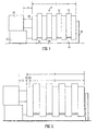
- Figure 1 represents a section of a brake assembly comprising a brake heat stack 1 comprising a plurality of carbon-carbon composite stator discs 10 keyed to a torque tube 11 and axially mounted about a wheel axle (not shown). Interleaved between the stator discs are a corresponding number of rotor discs 12 keyed to the inside of a wheel (not shown) for rotation with the wheel.
- the stator and rotor discs in the brake heat stack are brought into frictional engagement by the application of the braking load by a plurality of actuator rams 13 which are arrayed around the wheel axis but only one of which is visible in the figure.
- Each ram 13 is driven by a motor (not shown) through a gear and ball screw mechanism (not shown) housed within a respective electrically powered actuator module body 14.
- the plurality of actuator modules 14 are mounted around a brake plate 15 to which the torque tube is attached.
- the brake plate is non-rotatably mounted to the aircraft landing gear (not shown).
- a reaction member 16 is provided at the opposite end of the torque tube from the actuator modules to oppose the braking force applied by the actuators.
- an Electronic Control Unit (not shown) first determines the actuator position when the heat stack 1 is closed, i.e. when the rams 13 have moved forward until the discs 10 and 12 have closed together and there is no clearance between them.
- the fact that the heat stack has reached its position can be determined by the electric actuator motor current increasing above a predetermined level.
- the ram or actuator can be fitted with a load transducer.
- the position of the actuator ram when the brake heat stack is fully closed is determined by the ECU processing a signal from a resolver mounted on the motor shaft to monitor rotation of the motor.
- a resolver mounted on the motor shaft to monitor rotation of the motor.
- other position sensing means can be used such as a position sensor mounted directly to the actuator ram.
- the heat stack thickness 2 can be calculated by comparing the actuator ram contact position against one or more of the following known reference positions:
- the measured distance 3 is the length of the ram 13 between the actuator 14 and the adjacent disc.
- Figure 2 represents a section through the brake assembly of Figure 1 when the rotor discs and stator discs of the heat stack are at an elevated temperature following a braking event.
- the expansion of the carbon-carbon composite material in the axial direction causes an increase 5 in the length of the heat stack due to thermal expansion to give a new overall heat pack thickness 4.
- the actuator position for the fully closed heat stack is determined to calculate heat stack thickness at elevated temperature as outlined in Figure 1 for the heat stack at ambient temperature.
- the heat stack thickness at elevated temperature is greater than the heat stack thickness at ambient. If the wear condition of the brake is to be determined to ensure there is sufficient brake friction material heat mass in the heat stack prior to aircraft despatch then the heat stack length at ambient temperature must be determined prior to despatch. If the heat stack length is measured at elevated temperature it will then need to be corrected to an at ambient temperature value in order to establish the absolute heat stack thickness.
- Correction of the heat stack thickness to account for temperature difference above ambient can be carried out in the ECU by using algorithms to take into account heat stack temperature, heat stack thickness and thermal expansion of the heat stack in the axial direction.
- the heat stack temperature can be determined by the use of a thermocouple or thermocouples positioned in the heat stack to provide a representative temperature or, alternatively, by an algorithm in the ECU from brake heat stack mass, specific heat of the heat stack material and a calculated energy input during braking.
- the brake control system can also be used to determine remaining service cycles in a brake heat stack and hence extend the measurement of wear to create a predictive tool for maintenance planning.
- Such maintenance planning can be carried out using the following algorithms: 1. Current average service cycle Inputs: Brake energy estimation, Weight-On-Wheels (WOW), Aircraft usage monitor, brake usage monitor Outputs: Number of hot taxi snubs per service cycle, Number of cold taxi snubs per service cycle, average landing brake energy, number of service cycles completed, (standard deviations for all parameters to confirm the averages are meaningful) Description: The most effective way of determining a service cycle is probably to use WOW or wheel speed spin up to determine whether a take off or landing has occurred.
- a moving average service cycle By determining this event and counting the number of brake applications using a brake usage monitor a moving average service cycle can be determined.
- Average wear rate Inputs Absolute (ambient temperature) heat stack size, current average service cycle, number of service cycles completed
- Brake energy estimation Inputs Wheel speed, brake demand, aircraft mass, slip
- Outputs Brake energy input Description: Using the parameters described above an approximation of the energy input to the brake can be made. This can be used with wheelspeed data to classify brake applications as high/ low energy and taxi or landing stops. 4.
- Remaining service cycles to overhaul Current average service cycle, absolute (ambient temperature) heat stack size, reject size, average wear per service cycle
- Outputs Remaining service cycles Description: This function will determine the remaining amount of wearable material then divide it by the average wear rate per service cycle to give the remaining service cycles to overhaul.
Landscapes
- Engineering & Computer Science (AREA)
- General Engineering & Computer Science (AREA)
- Mechanical Engineering (AREA)
- Braking Arrangements (AREA)
Abstract
Description
- The invention relates to electrically actuated aircraft brakes and is more particularly but not exclusively concerned with the wear measurement and adjustment of such brakes.
- Aircraft brakes are typically of a multi disc type with carbon-carbon composite (C-C) friction discs and feature hydraulically actuated rams (pistons) to generate the clamping force across the brake heat pack to generate friction at the disc interfaces. A brake heat stack comprising C-C stator discs keyed to a non-rotating torque tube and C-C rotor discs keyed to the rotating wheel and interleaved between the stators generates the friction forces for braking and absorbs the kinetic energy of the aircraft as heat. Brake actuation is under the control of an electronic control unit (ECU) controlling braking force in response to a brake demand signal and monitoring braking through signals representing parameters such as brake pressure, brake torque, deceleration, wheel speed and skid activity.
- It is important for aircraft safety that the brake heat stacks have sufficient capacity to absorb the kinetic energy of the aircraft during an emergency braking event such as a Rejected-Take-Off. This requirement dictates a minimum heat stack mass that must be available and it is critical that the amount of material remaining in the brake heat stack, normally identified by the thickness of the heat stack, can be monitored to ensure that heat stacks are replaced at the appropriate time.
- Brake heat stack thickness is monitored manually by examining the length of a wear pin attached to the brake stator disc at the end of the brake heat stack where the brake pressure is applied. Such wear pins indicate the thickness of material remaining in the brake heat stack before maintenance action is required.
- As technology is introduced for the more electric aircraft there is an emerging trend towards using electrically powered actuator rams for aircraft brakes. In such actuators the movement to apply and release the brake clamping force in the actuator ram is driven by an electric motor through a mechanism such as gears or ball screws. The use of electric actuation allows the actuator to become more intelligent with the capability to provide information such as actuator position to the brake control system.
-
US 2004/0 084 252 describes a system in which wear is measured with an actuator composition sensor. Additionally, contribution to wear of each individual brake application is estimated, based on the measured brake stack temperature. -
US 6,003,640 in the name of Goodrich describes a system using position sensors coupled to the actuator ram to determine actuator ram position. By detecting the position of the actuator when it is in contact with the closed brake heat stack during a calibration routine and comparing this position with a previously determined reference position the brake heat stack wear is determined. - The use of wear pins in hydraulically actuated brakes and, for electric actuators, a system of the type proposed in
US 6,003,640 , takes no account of brake temperature when determining heat stack position and wear of the brake heat stack. - Expansion of the C-C brake heat stack is typically in the order of 12x10-6 °C-1. This is equivalent to 1.2mm per 1000°C per 100mm of heat stack thickness. For a typical medium size civil aircraft carbon-carbon brake heat stack with total thickness of 200mm this gives an expansion of 2.4mm between ambient and 1000°C. For a typical civil aircraft carbon-carbon brake heat stack with total thickness of 300mm this gives an expansion of 3.6mm between ambient and 1000°C.
- Thermal expansion of a brake friction material with a positive expansion coefficient will be a positive value when the brake heat stack is increasing in temperature and a negative value when the brake heat stack is cooling. When the brake heats during a braking cycle the heat stack will expand. When the brake cools down between braking cycles the heat stack will contract
- If the brake heat stack thickness is measured when the brake heat stack is at an elevated temperature then, when the heat stack then cools below the temperature at which the heat stack thickness was measured, the brake heat stack will contract due to the cooling, thereby decreasing the heat stack thickness. If the system is monitoring brake wear or amount of wear remaining in the brake heat stack a distorted assessment of wear or remaining material will be obtained, resulting in an incorrect evaluation of remaining cycles to overhaul if the system uses algorithms to assess remaining brake life.
- Brake control systems such as that featured in
WO 02/12043 - To obtain a measurement of brake heat stack thickness that can be used to derive accurate information on brake wear the determination of heat stack thickness can only be carried out when the brake is at ambient temperature, or at a temperature at which expansion is considered to be negligible.
- If automatic wear measurement is to replace visual inspection of the brakes, several problems must be overcome. Currently, it is the responsibility of the pilot to carry out a visual inspection of components such as the tyres, engines and brakes to ensure the aircraft meets operational requirements.
- If wear pins are removed from brake assemblies the pilot requires an indication of the health of the brake so that the pilot can fulfil his responsibilities. A user initiated wear measurement would give the necessary information, however the system detailed in
US 6,003,640 can only operate when the brake is at ambient temperature. As styles of operation change, some airlines run aircraft on an almost back to back schedule of flights with several different pilots flying any individual plane in a given tour of duty. Each one of these pilots must obtain an accurate wear measurement and will not be able to rely on a previous measurement taken that day as it could have been taken 20 flight cycles earlier. - Airlines are under increasing pressure to fully utilise their asset, so pressure to reduce turn round times - particularly for shorter flights, is high. The limiting factor is often brake temperature, as the brake must be capable of a full Rejected Take Off (RTO) before the aircraft can be released. Typically the limiting temperature is set at around 300°C, though it can be as high as 400°C. This could relate to an axial expansion of over 1 mm on a 300mm heat stack, resulting in an unacceptable error in wear measurement. For instance, if 0.1mm of wearable material was remaining at the start of a tour of duty, heavy wear or contamination of the heat stack with de-icer could occur and cause the brake to go below safe limits for heat stack size. Any wear measurement taken without temperature compensation at a temperature of 50° above ambient could result in a brake giving an indication that it is in a healthy condition when it is in fact below the allowable limit.
- For electrically actuated brakes the opportunity to carry out a calibrated heat stack wear measurement of the type proposed by
Goodrich in US 6,003,640 is limited to maintenance periods where the aircraft is out of service. In addition, information on heat stack wear is required to track wear of the heat pack in order to inform that maintenance is required so there is a need for representative wear information to be recorded on an ongoing basis during operating cycles. This cannot be provided if the actuator ram position for contact with the closed heat stack heat stack thickness is being determined as the position will change with brake temperature. - According to one aspect of the invention, there is proivided a method and apparatus for measuring and monitoring brake heat stack thickness to compensate for temperature variations above ambient temperature in the heat stack that would cause expansion of the brake heat stack.
- According to a second aspect of the invention, there is provided a method and apparatus for measuring and monitoring brake heat stack thickness to compensate for temperature variations above ambient temperature in the heat stack that would cause expansion of the brake heat stack and determining the equivalent heat stack thickness at ambient temperature.
- According to a third aspect of the invention, there is provided a method and apparatus for determining the point at which the actuator ram contacts the closed brake heat stack, calculating heat stack thickness from this position and compensating the brake heat stack thickness for any temperature difference above ambient to determine the equivalent heat stack thickness at ambient temperature.
- According to a fourth aspect of the invention, there is provided a method and apparatus for determining brake wear by calculating the measured actuator ram position or heat stack thickness to compensate for any temperature variation from ambient.
- According to a fourth aspect of the invention, there is provided a method and apparatus for predicting the remaining service life of a brake heat stack by determining brake wear by calculating the measured actuator ram position or heat stack thickness to compensate for any temperature variation from ambient and using the compensated brake wear figure to predict the remaining brake life.
- One exemplary embodiment of the invention comprises an aircraft braking systems utilising electrical actuation to apply the brake clamping load. Such brakes are known and typically comprise a multi disc brake heat stack and a servo-mechanism for application of brake pressure. The multi disc heat stack comprises:
- Carbon-Carbon composite (C-C) stator discs keyed to the torque tube fixedly mounted to a brake plate and mounted axially about an axle; and
- C-C rotor discs interleaved between the stator discs and keyed to the inside of a wheel that is rotatably mounted by bearing means to the axle.
- The servo mechanism consists of:
- A plurality of electric actuator modules fixedly mounted around a brake plate, each actuator comprising a motor driving, through a gear box mechanism, a ballscrew to produce linear motion in an actuator ram applying and withdrawing load to the brake heat stack.
- Position sensor to provide a signal representative of actuator position. The position sensor could be of a type connected to the actuator rams, however the sensor is preferably a resolver mounted so as to sense movement of the motor shaft. The use of a resolver is preferred as it is present in the system to measure motor speed and reduces the parts count in the actuator module if additional position sensors are not required. Position of the actuator ram is processed by the ECU through algorithms taking into account the motor shaft rotation signal from the resolver and gear ratios through the gearbox and ball screw mechanism to deduce the actuator movement and position from a reference point.
- Current sensor to detect motor current, this being representative of the load applied to the brake or, alternatively, a pressure load cell positioned within the brake to give a signal directly representative of brake load.
- Electronic Control Unit (ECU) capable of providing current to the motor for moving the actuator into and out of forceful engagement and controlling the position of the actuator relative to the feedback signal from the position sensor.
- Additional sensors are fitted as required for monitoring parameters such as temperature, wheel speed and brake torque.
- At ambient temperature the size of the heat stack is known following a calibration routine. The calibration routine can be carried out in a number of ways, however a preferred method would involve driving the actuator ram forward until the heat stack is closed. This condition is detected by an increase in the motor current above a predetermined value or by the use of a load cell to detect when the load in the actuator ram reaches a predetermined threshold. The actuator ram position and hence the position for the actuator contact face of the heat stack is then known from the information provided by the position sensor and processed by the electronic control unit (ECU).
- From the position at which the actuator ram contacts the heat stack the heat stack thickness can be calculated by comparing actuator ram contact position against one or more of the following known reference positions:
- the position of the opposite end face (reaction end) of the heat stack to give heat stack length;
- the position of the actuator contact face for a predetermined minimum heat stack thickness to give actual heat stack thickness, remaining brake material thickness and remaining brake life;
- the position of the actuator contact face when the heat stack was new to give the amount of brake wear.
- The measured brake heat pack position, and hence heat stack thickness, can be adjusted to compensate for brake temperature. If brake temperature is above ambient the equivalent heat pack position at ambient temperature can be calculated by algorithms in the software of the brake control ECU by reference to the thermal expansion and difference between actual heat stack temperature and ambient and recorded by the system.
- The brake temperature can be measured using a single thermocouple or a plurality of thermocouples placed in a position or position to give a temperature representative of the heat stack. Alternatively, the temperature can be calculated using measured parameters representative of the energy input to the brake during a braking event and heat stack mass, calculated from the remaining heat pack thickness.
- The temperature compensated brake heat stack position or brake heat stack thickness can then be compared against a reference value for the new heat stack to determine heat stack wear. Alternatively, it is preferable for the temperature compensated brake heat stack position or brake heat stack thickness to then be compared against a reference value for the fully worn heat stack to determine the amount of wearable material remaining and absolute heat stack size. This does away with the need for a separate brake wear determining step conducted at ambient temperature and allows brake heat stack wear to be measured and recorded throughout normal brake operation.
- With the ability to determine the absolute heat stack size during operation cycles of the aircraft the brake control system can also be used to determine remaining service cycles in a brake heat stack and hence extend the measurement of wear to create a predictive tool for maintenance planning. Such maintenance planning can be carried out using algorithms such as, for example:
- current average service cycle;
- average wear rate;
- brake energy estimation; and
- remaining service cycles to overhaul.
- In order that the invention may be well understood, embodiments thereof will now be described, by way of example only, with reference to the accompanying diagrammatic drawings in which:
-
Figure 1 shows the heat stack thickness for a fully closed heat stack at ambient temperature and -
Figure 2 shows the same heat stack at elevated temperature following a braking event actuation with the heat stack thickness increased by thermal expansion. -
Figure 1 represents a section of a brake assembly comprising abrake heat stack 1 comprising a plurality of carbon-carboncomposite stator discs 10 keyed to atorque tube 11 and axially mounted about a wheel axle (not shown). Interleaved between the stator discs are a corresponding number ofrotor discs 12 keyed to the inside of a wheel (not shown) for rotation with the wheel. The stator and rotor discs in the brake heat stack are brought into frictional engagement by the application of the braking load by a plurality of actuator rams 13 which are arrayed around the wheel axis but only one of which is visible in the figure. Eachram 13 is driven by a motor (not shown) through a gear and ball screw mechanism (not shown) housed within a respective electrically poweredactuator module body 14. The plurality ofactuator modules 14 are mounted around abrake plate 15 to which the torque tube is attached. The brake plate is non-rotatably mounted to the aircraft landing gear (not shown). Areaction member 16 is provided at the opposite end of the torque tube from the actuator modules to oppose the braking force applied by the actuators. - To measure the
heat pack thickness 2 at ambient temperature an Electronic Control Unit (ECU) (not shown) first determines the actuator position when theheat stack 1 is closed, i.e. when therams 13 have moved forward until thediscs - The position of the actuator ram when the brake heat stack is fully closed is determined by the ECU processing a signal from a resolver mounted on the motor shaft to monitor rotation of the motor. Alternatively, other position sensing means can be used such as a position sensor mounted directly to the actuator ram.
- From the position at which the actuator ram contacts the fully closed heat pack the
heat stack thickness 2 can be calculated by comparing the actuator ram contact position against one or more of the following known reference positions: - the position of the opposite end face (reaction end) of the heat pack to give heat stack length;
- the position of the actuator contact face for a predetermined minimum heat stack thickness to give actual heat stack thickness, remaining brake material thickness and remaining brake life;
- the position of the actuator contact face when the heat stack was new to give the amount of brake wear and hence the remaining heat pack thickness.
- The measured
distance 3 is the length of theram 13 between the actuator 14 and the adjacent disc. -
Figure 2 represents a section through the brake assembly ofFigure 1 when the rotor discs and stator discs of the heat stack are at an elevated temperature following a braking event. The expansion of the carbon-carbon composite material in the axial direction causes an increase 5 in the length of the heat stack due to thermal expansion to give a new overall heat pack thickness 4. The actuator position for the fully closed heat stack is determined to calculate heat stack thickness at elevated temperature as outlined inFigure 1 for the heat stack at ambient temperature. - The heat stack thickness at elevated temperature is greater than the heat stack thickness at ambient. If the wear condition of the brake is to be determined to ensure there is sufficient brake friction material heat mass in the heat stack prior to aircraft despatch then the heat stack length at ambient temperature must be determined prior to despatch. If the heat stack length is measured at elevated temperature it will then need to be corrected to an at ambient temperature value in order to establish the absolute heat stack thickness.
- Correction of the heat stack thickness to account for temperature difference above ambient can be carried out in the ECU by using algorithms to take into account heat stack temperature, heat stack thickness and thermal expansion of the heat stack in the axial direction.
- The heat stack temperature can be determined by the use of a thermocouple or thermocouples positioned in the heat stack to provide a representative temperature or, alternatively, by an algorithm in the ECU from brake heat stack mass, specific heat of the heat stack material and a calculated energy input during braking.
- With the ability to determine the absolute heat pack size during operating cycles of the aircraft the brake control system can also be used to determine remaining service cycles in a brake heat stack and hence extend the measurement of wear to create a predictive tool for maintenance planning. Such maintenance planning can be carried out using the following algorithms:
1. Current average service cycleInputs: Brake energy estimation, Weight-On-Wheels (WOW), Aircraft usage monitor, brake usage monitor Outputs: Number of hot taxi snubs per service cycle, Number of cold taxi snubs per service cycle, average landing brake energy, number of service cycles completed, (standard deviations for all parameters to confirm the averages are meaningful) Description: The most effective way of determining a service cycle is probably to use WOW or wheel speed spin up to determine whether a take off or landing has occurred. By determining this event and counting the number of brake applications using a brake usage monitor a moving average service cycle can be determined.
2. Average wear rateInputs: Absolute (ambient temperature) heat stack size, current average service cycle, number of service cycles completed Outputs: Wear rate per service cycle Description: By averaging wear over the current service cycles total, a good approximation of the wear per service cycle can be determined relative to the operating conditions of the particular aircraft.
3. Brake energy estimationInputs: Wheel speed, brake demand, aircraft mass, slip Outputs: Brake energy input Description: Using the parameters described above an approximation of the energy input to the brake can be made. This can be used with wheelspeed data to classify brake applications as high/ low energy and taxi or landing stops.
4. Remaining service cycles to overhaulInputs: Current average service cycle, absolute (ambient temperature) heat stack size, reject size, average wear per service cycle Outputs: Remaining service cycles Description: This function will determine the remaining amount of wearable material then divide it by the average wear rate per service cycle to give the remaining service cycles to overhaul. - These algorithms utilise historic data on aircraft usage to determine the average wear rate and amount of wear remaining to predict the number of service cycles remaining before the heat stack will reach a fully worn or reject thickness.
Claims (10)
- A method for monitoring an aircraft braking system having a brake heat stack (1) comprising brake discs (10, 12); the method including measuring the brake heat stack thickness (2) to determine wear of the brake discs and being characterised by adjusting the measurement to compensate for temperature variations above ambient temperature in the heat stack (1) that would cause expansion of the brake heat stack.
- A method according to Claim 1, including determining the equivalent heat stack thickness at ambient temperature.
- A method according to Claim 1, including determining the point at which an actuator ram (13) contacts the closed heat stack calculating heat pack thickness from this position, and compensating the brake heat stack thickness for any temperature difference above ambient to determine the equivalent heat stack thickness at ambient temperature.
- A method according to Claim 3, for determining brake wear by calculating the measured actuator ram position or heat stack thickness (2) to compensate for any temperature variation from ambient.
- A method according to Claim 4, including predicting the remaining service life fo a brake heat stack (1) by determining brake wear by calculating the measured actuator ram position or heat stack thickness to compensate for any temperature variation from ambient and using the compensated brake wear figure to predict the remaining brake life.
- Apparatus for monitoring an aircraft braking system having a brake heat stack (1) comprising brake discs (10, 12), the apparatus including means for measuring the brake heat stack thickness (2) to determine wear of the brake discs, and being characterised by means for adjusting the measurement to compensate for temperature variations above ambient temperature in the heat stack (1) that would cause expansion of the brake heat stack.
- Apparatus according to Claim 6, including means for determining the equivalent heat stack thickness at ambient temperature.
- Apparatus according to Claim 6, including means for determining the point at which an actuator ram (13) contacts the closed heat stack and calculating heat stack thickness from this position, and means for compensating the brake heat stack thickness for any temperature difference above ambient to determine the equivalent heat stack thickness at ambient temperature.
- Apparatus according to Claim 8, including means for determining brake wear by calculating the measured actuator ram position or heat stack thickness (2) to compensate for any temperature variation from ambient.
- Apparatus according to Claim 9, including means for predicting the remaining service life of a heat stack (1) by determining brake wear by calculating the measured actuator ram position or heat stack thickness to compensate for any temperature variation from ambient and using the compensated brake wear figure to predict the remaining brake life.
Applications Claiming Priority (2)
| Application Number | Priority Date | Filing Date | Title |
|---|---|---|---|
| GBGB0500304.1A GB0500304D0 (en) | 2005-01-08 | 2005-01-08 | Electrically actuated aircraft brakes |
| PCT/GB2006/000062 WO2006072802A1 (en) | 2005-01-08 | 2006-01-09 | Electrically actuated aircraft brakes |
Publications (2)
| Publication Number | Publication Date |
|---|---|
| EP1834109A1 EP1834109A1 (en) | 2007-09-19 |
| EP1834109B1 true EP1834109B1 (en) | 2010-03-03 |
Family
ID=34203762
Family Applications (1)
| Application Number | Title | Priority Date | Filing Date |
|---|---|---|---|
| EP06703327A Expired - Lifetime EP1834109B1 (en) | 2005-01-08 | 2006-01-09 | Electrically actuated aircraft brakes |
Country Status (8)
| Country | Link |
|---|---|
| US (1) | US7673721B2 (en) |
| EP (1) | EP1834109B1 (en) |
| BR (1) | BRPI0606291B1 (en) |
| CA (1) | CA2588524C (en) |
| DE (1) | DE602006012617D1 (en) |
| ES (1) | ES2340794T3 (en) |
| GB (1) | GB0500304D0 (en) |
| WO (1) | WO2006072802A1 (en) |
Families Citing this family (26)
| Publication number | Priority date | Publication date | Assignee | Title |
|---|---|---|---|---|
| GB0500305D0 (en) * | 2005-01-08 | 2005-02-16 | Dunlop Aerospace Ltd | Electrically actuated aircraft brakes |
| DE102007004604A1 (en) * | 2007-01-30 | 2008-07-31 | Siemens Ag | Electromechanical disc brake e.g. wedge brake, operational parameter e.g. lifting clearance, determining method for motor vehicle involves bringing brake lining into contact points with brake disk for detecting position of points |
| GB2457376B (en) * | 2008-02-14 | 2011-12-07 | Goodrich Corp | Brake wear measurement system |
| US9441692B2 (en) * | 2008-03-11 | 2016-09-13 | Honeywell International Inc. | Proximity sensor for brake wear detection |
| JP2011121669A (en) * | 2009-12-09 | 2011-06-23 | Nippon Otis Elevator Co | Abnormality detecting device of electromagnetic brake in elevator |
| US9096204B2 (en) * | 2012-12-12 | 2015-08-04 | Goodrich Corporation | System and method for determining an adaptive turnaround threshold |
| US9545903B2 (en) * | 2015-02-02 | 2017-01-17 | Goodrich Corporation | Electromechanical brake actuator with variable speed epicyclic gearbox |
| US9482301B2 (en) | 2015-03-25 | 2016-11-01 | Honeywell International Inc. | Brake disc stack wear measurement |
| US10570974B2 (en) | 2015-04-17 | 2020-02-25 | Goodrich Corporation | Brake position and wear detection systems and methods |
| US10093298B2 (en) * | 2016-01-08 | 2018-10-09 | Goodrich Corporation | Abnormal brake behavior detection |
| GB2549736A (en) * | 2016-04-26 | 2017-11-01 | Airbus Operations Ltd | Predicting brake cooling periods |
| US10807576B2 (en) * | 2016-11-09 | 2020-10-20 | Allison Transmission, Inc. | Brake actuator-based prognostic system and method thereof |
| US10493962B2 (en) | 2017-07-24 | 2019-12-03 | Goodrich Corporation | Brake position system |
| US10800386B2 (en) | 2017-07-24 | 2020-10-13 | Goodrich Corporation | Brake position system |
| AT520073B1 (en) * | 2017-10-05 | 2019-01-15 | Ve Vienna Engineering Forschungs Und Entw Gmbh | Method and brake control for actuating a friction brake |
| EP3480485B1 (en) | 2017-11-06 | 2026-01-21 | Ratier-Figeac SAS | Brake assembly indicator |
| GB2571359A (en) | 2018-02-27 | 2019-08-28 | Airbus Operations Ltd | Brake monitoring |
| US10471947B1 (en) | 2018-04-27 | 2019-11-12 | Honeywell International Inc. | Determining estimated remaining use of brake assembly by transceiver |
| US10941826B2 (en) | 2018-09-12 | 2021-03-09 | Honeywell International Inc. | Determining estimated remaining use of brake assembly |
| US10823244B2 (en) * | 2018-11-30 | 2020-11-03 | Goodrich Corporation | Spring based brake wear sensor |
| GB2583486A (en) * | 2019-04-29 | 2020-11-04 | Airbus Operations Ltd | Brake characteristics |
| FI129996B (en) * | 2020-06-03 | 2022-12-15 | Ponsse Oyj | Braking device for working machine |
| CN113236694B (en) * | 2021-04-01 | 2022-04-19 | 中国长江电力股份有限公司 | Self-resetting air brake braking device of large hydroelectric generator and abrasion detection method |
| US12486050B2 (en) * | 2022-02-10 | 2025-12-02 | Goodrich Corporation | Hybrid brake systems and methods |
| AU2023201226B2 (en) * | 2022-03-07 | 2024-09-26 | Tink, Rodney Peter | Wear monitoring system for lubricant-immersed disc brakes |
| US20260084676A1 (en) * | 2024-09-20 | 2026-03-26 | Ford Global Technologies, Llc | Methods and apparatus to monitor a condition of a braking system |
Family Cites Families (8)
| Publication number | Priority date | Publication date | Assignee | Title |
|---|---|---|---|---|
| US6003640A (en) | 1997-05-09 | 1999-12-21 | The B.F. Goodrich Company | Electronic braking system with brake wear measurement and running clearance adjustment |
| US5939978A (en) * | 1997-07-17 | 1999-08-17 | Meritor Heavy Vehicle Systems, Llc | Temperature sensing brake lining wear indicator |
| WO2002012043A1 (en) | 2000-08-04 | 2002-02-14 | Dunlop Aerospace Limited | Brake condition monitoring |
| US6659233B2 (en) * | 2001-12-04 | 2003-12-09 | Hydro-Aire, Inc. | System and method for aircraft braking system usage monitoring |
| DE10259529B4 (en) * | 2002-12-19 | 2005-02-17 | Daimlerchrysler Ag | Method for determining a brake condition |
| US6959794B2 (en) * | 2003-05-30 | 2005-11-01 | Goodrich Corporation | Low power parking brake force adjustment apparatus and method for electrically actuated brake systems |
| JP4463812B2 (en) * | 2004-06-21 | 2010-05-19 | 日立オートモティブシステムズ株式会社 | Electric brake |
| GB0500305D0 (en) * | 2005-01-08 | 2005-02-16 | Dunlop Aerospace Ltd | Electrically actuated aircraft brakes |
-
2005
- 2005-01-08 GB GBGB0500304.1A patent/GB0500304D0/en not_active Ceased
-
2006
- 2006-01-09 US US11/577,757 patent/US7673721B2/en active Active
- 2006-01-09 EP EP06703327A patent/EP1834109B1/en not_active Expired - Lifetime
- 2006-01-09 BR BRPI0606291A patent/BRPI0606291B1/en active IP Right Grant
- 2006-01-09 WO PCT/GB2006/000062 patent/WO2006072802A1/en not_active Ceased
- 2006-01-09 CA CA2588524A patent/CA2588524C/en not_active Expired - Lifetime
- 2006-01-09 DE DE602006012617T patent/DE602006012617D1/en not_active Expired - Lifetime
- 2006-01-09 ES ES06703327T patent/ES2340794T3/en not_active Expired - Lifetime
Also Published As
| Publication number | Publication date |
|---|---|
| DE602006012617D1 (en) | 2010-04-15 |
| BRPI0606291A2 (en) | 2009-06-09 |
| ES2340794T3 (en) | 2010-06-09 |
| EP1834109A1 (en) | 2007-09-19 |
| US7673721B2 (en) | 2010-03-09 |
| CA2588524A1 (en) | 2006-07-13 |
| GB0500304D0 (en) | 2005-02-16 |
| BRPI0606291B1 (en) | 2018-12-11 |
| US20090084637A1 (en) | 2009-04-02 |
| WO2006072802A1 (en) | 2006-07-13 |
| CA2588524C (en) | 2013-04-30 |
Similar Documents
| Publication | Publication Date | Title |
|---|---|---|
| CA2588524C (en) | Electrically actuated aircraft brakes | |
| US8230983B2 (en) | Electrically actuated aircraft brakes | |
| EP3354523B1 (en) | Fault detection based on brake torque and temperature | |
| KR100697447B1 (en) | Electronic aircraft brake system with brake wear measurement mechanism, operating clearance adjustment mechanism and multiple electric motor-actuator ram assemblies | |
| EP3239007B1 (en) | Predicting brake cooling periods | |
| US8634971B2 (en) | Brake wear control system | |
| US11077838B2 (en) | Technique for determining a wear valve, which indicates wear of a friction lining of a vehicle brake | |
| CN107921950B (en) | Method and system for analyzing wear characteristics of brake linings | |
| EP3909818B1 (en) | Detection of brake failure using wheel speed during landing gear retraction | |
| US20200172077A1 (en) | Temperature monitoring to detect brake failure | |
| US6224017B1 (en) | Brake for a lift flap adjustment mechanism | |
| US7469593B2 (en) | Piezo-electric force sensor and method | |
| EP4067687B1 (en) | Brake wear pin architecture | |
| US20040245053A1 (en) | Method of controlling an electromechanical aircraft brake | |
| EP4382373B1 (en) | Aircraft brake assembly sensing device | |
| US20050216160A1 (en) | Method for detecting electric-mechanical-brake pad drag and/or calculating actuator efficiency |
Legal Events
| Date | Code | Title | Description |
|---|---|---|---|
| PUAI | Public reference made under article 153(3) epc to a published international application that has entered the european phase |
Free format text: ORIGINAL CODE: 0009012 |
|
| 17P | Request for examination filed |
Effective date: 20070416 |
|
| AK | Designated contracting states |
Kind code of ref document: A1 Designated state(s): DE ES FR GB IT |
|
| RBV | Designated contracting states (corrected) |
Designated state(s): DE ES FR GB IT |
|
| DAX | Request for extension of the european patent (deleted) | ||
| RAP1 | Party data changed (applicant data changed or rights of an application transferred) |
Owner name: MEGGITT AEROSPACE LIMITED |
|
| GRAP | Despatch of communication of intention to grant a patent |
Free format text: ORIGINAL CODE: EPIDOSNIGR1 |
|
| GRAS | Grant fee paid |
Free format text: ORIGINAL CODE: EPIDOSNIGR3 |
|
| GRAA | (expected) grant |
Free format text: ORIGINAL CODE: 0009210 |
|
| AK | Designated contracting states |
Kind code of ref document: B1 Designated state(s): DE ES FR GB IT |
|
| REG | Reference to a national code |
Ref country code: GB Ref legal event code: FG4D |
|
| REF | Corresponds to: |
Ref document number: 602006012617 Country of ref document: DE Date of ref document: 20100415 Kind code of ref document: P |
|
| REG | Reference to a national code |
Ref country code: ES Ref legal event code: FG2A Ref document number: 2340794 Country of ref document: ES Kind code of ref document: T3 |
|
| PLBE | No opposition filed within time limit |
Free format text: ORIGINAL CODE: 0009261 |
|
| STAA | Information on the status of an ep patent application or granted ep patent |
Free format text: STATUS: NO OPPOSITION FILED WITHIN TIME LIMIT |
|
| 26N | No opposition filed |
Effective date: 20101206 |
|
| REG | Reference to a national code |
Ref country code: FR Ref legal event code: PLFP Year of fee payment: 11 |
|
| REG | Reference to a national code |
Ref country code: FR Ref legal event code: PLFP Year of fee payment: 12 |
|
| REG | Reference to a national code |
Ref country code: FR Ref legal event code: PLFP Year of fee payment: 13 |
|
| REG | Reference to a national code |
Ref country code: DE Ref legal event code: R082 Ref document number: 602006012617 Country of ref document: DE Representative=s name: MEISSNER BOLTE PATENTANWAELTE RECHTSANWAELTE P, DE |
|
| PGFP | Annual fee paid to national office [announced via postgrant information from national office to epo] |
Ref country code: DE Payment date: 20250129 Year of fee payment: 20 |
|
| PGFP | Annual fee paid to national office [announced via postgrant information from national office to epo] |
Ref country code: ES Payment date: 20250203 Year of fee payment: 20 |
|
| PGFP | Annual fee paid to national office [announced via postgrant information from national office to epo] |
Ref country code: FR Payment date: 20250127 Year of fee payment: 20 |
|
| PGFP | Annual fee paid to national office [announced via postgrant information from national office to epo] |
Ref country code: IT Payment date: 20250121 Year of fee payment: 20 Ref country code: GB Payment date: 20250127 Year of fee payment: 20 |
|
| REG | Reference to a national code |
Ref country code: DE Ref legal event code: R071 Ref document number: 602006012617 Country of ref document: DE |
|
| REG | Reference to a national code |
Ref country code: ES Ref legal event code: FD2A Effective date: 20260127 |
|
| REG | Reference to a national code |
Ref country code: GB Ref legal event code: PE20 Expiry date: 20260108 |
|
| PG25 | Lapsed in a contracting state [announced via postgrant information from national office to epo] |
Ref country code: ES Free format text: LAPSE BECAUSE OF EXPIRATION OF PROTECTION Effective date: 20260110 |