EP1834020B1 - Improved electroblowing web formation process - Google Patents
Improved electroblowing web formation process Download PDFInfo
- Publication number
- EP1834020B1 EP1834020B1 EP05855886A EP05855886A EP1834020B1 EP 1834020 B1 EP1834020 B1 EP 1834020B1 EP 05855886 A EP05855886 A EP 05855886A EP 05855886 A EP05855886 A EP 05855886A EP 1834020 B1 EP1834020 B1 EP 1834020B1
- Authority
- EP
- European Patent Office
- Prior art keywords
- polymer
- stream
- spinneret
- spinning nozzle
- electrode
- Prior art date
- Legal status (The legal status is an assumption and is not a legal conclusion. Google has not performed a legal analysis and makes no representation as to the accuracy of the status listed.)
- Ceased
Links
- 238000000034 method Methods 0.000 title claims abstract description 43
- 230000015572 biosynthetic process Effects 0.000 title description 3
- 229920000642 polymer Polymers 0.000 claims abstract description 63
- 238000009987 spinning Methods 0.000 claims abstract description 41
- 230000005684 electric field Effects 0.000 claims abstract description 16
- 239000002121 nanofiber Substances 0.000 claims abstract description 12
- 239000002904 solvent Substances 0.000 claims description 6
- 238000003860 storage Methods 0.000 claims description 3
- 239000000835 fiber Substances 0.000 description 14
- -1 polyaramide Polymers 0.000 description 7
- 229920003171 Poly (ethylene oxide) Polymers 0.000 description 6
- 238000001523 electrospinning Methods 0.000 description 3
- 239000003795 chemical substances by application Substances 0.000 description 2
- 230000003247 decreasing effect Effects 0.000 description 2
- 239000000155 melt Substances 0.000 description 2
- BDAGIHXWWSANSR-UHFFFAOYSA-N methanoic acid Natural products OC=O BDAGIHXWWSANSR-UHFFFAOYSA-N 0.000 description 2
- 229920003207 poly(ethylene-2,6-naphthalate) Polymers 0.000 description 2
- 229920001707 polybutylene terephthalate Polymers 0.000 description 2
- 239000011112 polyethylene naphthalate Substances 0.000 description 2
- 229920000139 polyethylene terephthalate Polymers 0.000 description 2
- 239000005020 polyethylene terephthalate Substances 0.000 description 2
- 239000004800 polyvinyl chloride Substances 0.000 description 2
- 229920000915 polyvinyl chloride Polymers 0.000 description 2
- 229920003048 styrene butadiene rubber Polymers 0.000 description 2
- OSWFIVFLDKOXQC-UHFFFAOYSA-N 4-(3-methoxyphenyl)aniline Chemical compound COC1=CC=CC(C=2C=CC(N)=CC=2)=C1 OSWFIVFLDKOXQC-UHFFFAOYSA-N 0.000 description 1
- 239000004677 Nylon Substances 0.000 description 1
- 229920002292 Nylon 6 Polymers 0.000 description 1
- 239000002033 PVDF binder Substances 0.000 description 1
- 239000004693 Polybenzimidazole Substances 0.000 description 1
- 239000004697 Polyetherimide Substances 0.000 description 1
- 239000004642 Polyimide Substances 0.000 description 1
- 239000004743 Polypropylene Substances 0.000 description 1
- 239000004793 Polystyrene Substances 0.000 description 1
- 239000004372 Polyvinyl alcohol Substances 0.000 description 1
- 239000002174 Styrene-butadiene Substances 0.000 description 1
- 239000000654 additive Substances 0.000 description 1
- 238000007664 blowing Methods 0.000 description 1
- 238000006243 chemical reaction Methods 0.000 description 1
- 230000000052 comparative effect Effects 0.000 description 1
- 239000002131 composite material Substances 0.000 description 1
- 150000001875 compounds Chemical class 0.000 description 1
- 239000012141 concentrate Substances 0.000 description 1
- 229920001577 copolymer Polymers 0.000 description 1
- 230000008878 coupling Effects 0.000 description 1
- 238000010168 coupling process Methods 0.000 description 1
- 238000005859 coupling reaction Methods 0.000 description 1
- 239000008367 deionised water Substances 0.000 description 1
- 229910021641 deionized water Inorganic materials 0.000 description 1
- 238000009792 diffusion process Methods 0.000 description 1
- 239000002019 doping agent Substances 0.000 description 1
- 238000005516 engineering process Methods 0.000 description 1
- 235000019253 formic acid Nutrition 0.000 description 1
- 239000003317 industrial substance Substances 0.000 description 1
- 239000003999 initiator Substances 0.000 description 1
- 238000004519 manufacturing process Methods 0.000 description 1
- 239000002184 metal Substances 0.000 description 1
- 229920001778 nylon Polymers 0.000 description 1
- 239000004014 plasticizer Substances 0.000 description 1
- 229920002239 polyacrylonitrile Polymers 0.000 description 1
- 229920000767 polyaniline Polymers 0.000 description 1
- 229920002480 polybenzimidazole Polymers 0.000 description 1
- 229920001601 polyetherimide Polymers 0.000 description 1
- 229920001721 polyimide Polymers 0.000 description 1
- 229920001155 polypropylene Polymers 0.000 description 1
- 229920002223 polystyrene Polymers 0.000 description 1
- 229920002451 polyvinyl alcohol Polymers 0.000 description 1
- 239000011148 porous material Substances 0.000 description 1
- 229920005989 resin Polymers 0.000 description 1
- 239000011347 resin Substances 0.000 description 1
- 238000003892 spreading Methods 0.000 description 1
- 239000003381 stabilizer Substances 0.000 description 1
- 125000000383 tetramethylene group Chemical group [H]C([H])([*:1])C([H])([H])C([H])([H])C([H])([H])[*:2] 0.000 description 1
- 229920002554 vinyl polymer Polymers 0.000 description 1
- XLYOFNOQVPJJNP-UHFFFAOYSA-N water Chemical compound O XLYOFNOQVPJJNP-UHFFFAOYSA-N 0.000 description 1
Images

Classifications
-
- D—TEXTILES; PAPER
- D01—NATURAL OR MAN-MADE THREADS OR FIBRES; SPINNING
- D01D—MECHANICAL METHODS OR APPARATUS IN THE MANUFACTURE OF ARTIFICIAL FILAMENTS, THREADS, FIBRES, BRISTLES OR RIBBONS
- D01D5/00—Formation of filaments, threads, or the like
- D01D5/0007—Electro-spinning
- D01D5/0061—Electro-spinning characterised by the electro-spinning apparatus
- D01D5/0092—Electro-spinning characterised by the electro-spinning apparatus characterised by the electrical field, e.g. combined with a magnetic fields, using biased or alternating fields
-
- D—TEXTILES; PAPER
- D04—BRAIDING; LACE-MAKING; KNITTING; TRIMMINGS; NON-WOVEN FABRICS
- D04H—MAKING TEXTILE FABRICS, e.g. FROM FIBRES OR FILAMENTARY MATERIAL; FABRICS MADE BY SUCH PROCESSES OR APPARATUS, e.g. FELTS, NON-WOVEN FABRICS; COTTON-WOOL; WADDING ; NON-WOVEN FABRICS FROM STAPLE FIBRES, FILAMENTS OR YARNS, BONDED WITH AT LEAST ONE WEB-LIKE MATERIAL DURING THEIR CONSOLIDATION
- D04H1/00—Non-woven fabrics formed wholly or mainly of staple fibres or like relatively short fibres
- D04H1/70—Non-woven fabrics formed wholly or mainly of staple fibres or like relatively short fibres characterised by the method of forming fleeces or layers, e.g. reorientation of fibres
- D04H1/72—Non-woven fabrics formed wholly or mainly of staple fibres or like relatively short fibres characterised by the method of forming fleeces or layers, e.g. reorientation of fibres the fibres being randomly arranged
- D04H1/728—Non-woven fabrics formed wholly or mainly of staple fibres or like relatively short fibres characterised by the method of forming fleeces or layers, e.g. reorientation of fibres the fibres being randomly arranged by electro-spinning
-
- D—TEXTILES; PAPER
- D01—NATURAL OR MAN-MADE THREADS OR FIBRES; SPINNING
- D01D—MECHANICAL METHODS OR APPARATUS IN THE MANUFACTURE OF ARTIFICIAL FILAMENTS, THREADS, FIBRES, BRISTLES OR RIBBONS
- D01D5/00—Formation of filaments, threads, or the like
-
- D—TEXTILES; PAPER
- D01—NATURAL OR MAN-MADE THREADS OR FIBRES; SPINNING
- D01D—MECHANICAL METHODS OR APPARATUS IN THE MANUFACTURE OF ARTIFICIAL FILAMENTS, THREADS, FIBRES, BRISTLES OR RIBBONS
- D01D5/00—Formation of filaments, threads, or the like
- D01D5/0007—Electro-spinning
- D01D5/0061—Electro-spinning characterised by the electro-spinning apparatus
- D01D5/0069—Electro-spinning characterised by the electro-spinning apparatus characterised by the spinning section, e.g. capillary tube, protrusion or pin
-
- D—TEXTILES; PAPER
- D01—NATURAL OR MAN-MADE THREADS OR FIBRES; SPINNING
- D01F—CHEMICAL FEATURES IN THE MANUFACTURE OF ARTIFICIAL FILAMENTS, THREADS, FIBRES, BRISTLES OR RIBBONS; APPARATUS SPECIALLY ADAPTED FOR THE MANUFACTURE OF CARBON FILAMENTS
- D01F6/00—Monocomponent artificial filaments or the like of synthetic polymers; Manufacture thereof
- D01F6/58—Monocomponent artificial filaments or the like of synthetic polymers; Manufacture thereof from homopolycondensation products
- D01F6/66—Monocomponent artificial filaments or the like of synthetic polymers; Manufacture thereof from homopolycondensation products from polyethers
-
- D—TEXTILES; PAPER
- D04—BRAIDING; LACE-MAKING; KNITTING; TRIMMINGS; NON-WOVEN FABRICS
- D04H—MAKING TEXTILE FABRICS, e.g. FROM FIBRES OR FILAMENTARY MATERIAL; FABRICS MADE BY SUCH PROCESSES OR APPARATUS, e.g. FELTS, NON-WOVEN FABRICS; COTTON-WOOL; WADDING ; NON-WOVEN FABRICS FROM STAPLE FIBRES, FILAMENTS OR YARNS, BONDED WITH AT LEAST ONE WEB-LIKE MATERIAL DURING THEIR CONSOLIDATION
- D04H1/00—Non-woven fabrics formed wholly or mainly of staple fibres or like relatively short fibres
- D04H1/40—Non-woven fabrics formed wholly or mainly of staple fibres or like relatively short fibres from fleeces or layers composed of fibres without existing or potential cohesive properties
- D04H1/54—Non-woven fabrics formed wholly or mainly of staple fibres or like relatively short fibres from fleeces or layers composed of fibres without existing or potential cohesive properties by welding together the fibres, e.g. by partially melting or dissolving
- D04H1/56—Non-woven fabrics formed wholly or mainly of staple fibres or like relatively short fibres from fleeces or layers composed of fibres without existing or potential cohesive properties by welding together the fibres, e.g. by partially melting or dissolving in association with fibre formation, e.g. immediately following extrusion of staple fibres
-
- D—TEXTILES; PAPER
- D04—BRAIDING; LACE-MAKING; KNITTING; TRIMMINGS; NON-WOVEN FABRICS
- D04H—MAKING TEXTILE FABRICS, e.g. FROM FIBRES OR FILAMENTARY MATERIAL; FABRICS MADE BY SUCH PROCESSES OR APPARATUS, e.g. FELTS, NON-WOVEN FABRICS; COTTON-WOOL; WADDING ; NON-WOVEN FABRICS FROM STAPLE FIBRES, FILAMENTS OR YARNS, BONDED WITH AT LEAST ONE WEB-LIKE MATERIAL DURING THEIR CONSOLIDATION
- D04H3/00—Non-woven fabrics formed wholly or mainly of yarns or like filamentary material of substantial length
- D04H3/02—Non-woven fabrics formed wholly or mainly of yarns or like filamentary material of substantial length characterised by the method of forming fleeces or layers, e.g. reorientation of yarns or filaments
- D04H3/03—Non-woven fabrics formed wholly or mainly of yarns or like filamentary material of substantial length characterised by the method of forming fleeces or layers, e.g. reorientation of yarns or filaments at random
-
- D—TEXTILES; PAPER
- D04—BRAIDING; LACE-MAKING; KNITTING; TRIMMINGS; NON-WOVEN FABRICS
- D04H—MAKING TEXTILE FABRICS, e.g. FROM FIBRES OR FILAMENTARY MATERIAL; FABRICS MADE BY SUCH PROCESSES OR APPARATUS, e.g. FELTS, NON-WOVEN FABRICS; COTTON-WOOL; WADDING ; NON-WOVEN FABRICS FROM STAPLE FIBRES, FILAMENTS OR YARNS, BONDED WITH AT LEAST ONE WEB-LIKE MATERIAL DURING THEIR CONSOLIDATION
- D04H3/00—Non-woven fabrics formed wholly or mainly of yarns or like filamentary material of substantial length
- D04H3/08—Non-woven fabrics formed wholly or mainly of yarns or like filamentary material of substantial length characterised by the method of strengthening or consolidating
- D04H3/16—Non-woven fabrics formed wholly or mainly of yarns or like filamentary material of substantial length characterised by the method of strengthening or consolidating with bonds between thermoplastic filaments produced in association with filament formation, e.g. immediately following extrusion
-
- B—PERFORMING OPERATIONS; TRANSPORTING
- B82—NANOTECHNOLOGY
- B82Y—SPECIFIC USES OR APPLICATIONS OF NANOSTRUCTURES; MEASUREMENT OR ANALYSIS OF NANOSTRUCTURES; MANUFACTURE OR TREATMENT OF NANOSTRUCTURES
- B82Y40/00—Manufacture or treatment of nanostructures
Definitions
- the present invention relates to a process for forming a fibrous web wherein a polymer stream is spun through a spinning nozzle into an electric field of sufficient strength to impart electrical charge on the polymer and wherein a forwarding gas stream aids in transporting the polymer away from the spinning nozzle.
- PCT publication no. WO 03/080905A discloses an apparatus and method for producing a nanofiber web.
- the method comprises feeding a polymer solution to a spinning nozzle to which a high voltage is applied while compressed gas is used to envelop the polymer solution in a forwarding gas stream as it exits the nozzle, and collecting the resulting nanofiber web on a grounded suction collector.
- One disadvantage of the prior art is the necessity of using a quite high voltage. In order to impart electrical charge on the polymer, an electrical field of sufficient strength is needed. Due to the distances involved between the spinning nozzle and the collector, high voltage is used to maintain the electric field. An object of this invention is to lower the voltage used.
- Still another disadvantage of the prior art is the coupling of the spinning nozzle to collector distance to the voltage used. During operation of the prior art process, it may be desirable to change the distance of the spinning nozzle to the collector. However, by changing that distance the electric field generated between the spinning nozzle and the collector changes. This requires changing the voltage in order to maintain the same electric field. Another objective of this invention is to decouple the spinning nozzle to collector distance from the electric field.
- a first embodiment of the present invention is directed to an electroblowing process for forming a fibrous web comprising feeding a polymer stream comprising a polymer and a solvent, or a polymer melt, from a storage tank or an extruder respectively, to a spinning nozzle located in a spinneret, issuing an electrically charged polymer stream from the spinning nozzle into a gas stream discharged from gas nozzles disposed adjacent to said spinning nozzle and collecting nanofibers formed from the charged polymer stream on a collector as a fibrous web, characterized by passing the electrically charged polymer stream by a grounded electrode, wherein a voltage is applied to the spinneret such that an electric field is generated between the spinneret and the electrode of sufficient strength to impart said electrical charge to the polymer stream as it issues from the spinning nozzle, wherein said electrode is positioned at a distance of between 0.01 cm to 100 cm from the exit of the spinning nozzle.
- electro-blown spinning refer interchangeably to a process for forming a fibrous web by which a forwarding gas stream is directed generally towards a collector, into which gas stream a polymer stream is injected from a spinning nozzle, thereby forming a fibrous web which is collected on the collector, wherein a voltage differential is maintained between the spinning nozzle and an electrode and the voltage differential is of sufficient strength to impart charge on the polymer as it issues from the spinning nozzle.
- nanofibers refers to fibers having diameters of less than 1,000 nanometers.
- a polymer stream comprising a polymer and a solvent, or a polymer melt
- a storage tank or in the case of a polymer melt from an extruder 100 to a spinning nozzle 104 (also referred to as a "die") located in a spinneret 102 through which the polymer stream is discharged.
- the polymer stream passes through an electric field generated between spinneret 102 and electrodes 140 and 142 as it is discharged from the spinneret 102.
- Compressed gas which may optionally be heated or cooled in a gas temperature controller 108, is issued from gas nozzles 106 disposed adjacent to or peripherally to the spinning nozzle 104.
- the gas is directed generally in the direction of the polymer stream flow, in a forwarding gas stream which forward the newly issued polymer stream and aids in the formation of the fibrous web.
- the forwarding gas stream provides the majority of the forwarding forces in the initial stages of drawing of the fibers from the issued polymer stream and in the case of polymer solution, simultaneously strips away the mass boundary layer along the individual fiber surface thereby greatly increasing the diffusion rate of solvent from the polymer solution in the form of gas during the formation of the fibrous web.
- the local electric field around polymer stream is of sufficient strength that the electrical force becomes the dominant drawing force which ultimately draws individual fibers from the polymer stream to diameters measured in the hundreds of nanometers or less.
- the angular geometry of the tip of the spinning nozzle 104 also referred to as the "die tip," creates an intense electric field in the three-dimensional space surrounding the tip which causes charge to be imparted to the polymer stream.
- the die tip may be in the form of a capillary of any desired cross-sectional shape, or in the form of a linear array of such capillaries.
- the forwarding gas stream is issued from gas nozzles 106 on each side of the spinneret 102.
- the gas nozzles are in the form of slots formed between elongated knife edges, one on each side of the spinneret 102, along the length of the linear capillary array, and the spinneret 102.
- the gas nozzle 106 may be in the form of a circumferential slot surrounding the spinneret 102.
- the gas nozzles 106 are directed toward the spinning nozzle, generally in the direction of the polymer stream flow.
- the angular die tip, and therefore the spinning nozzle(s) is positioned such that it extends beyond the end of the spinneret and gas nozzles a distance "e" ( Fig. 2 ). It is believed that the electric field combined with the charge on the polymer stream provides spreading forces which act on the fibers and fibrils formed therein, causing the web to be better dispersed and providing for very uniform web laydown on the collection surface of the collector.
- the polymer solution is electrically conductive.
- polymers for use in the invention may include polyimide, nylon, polyaramide, polybenzimidazole, polyetherimide, polyacrylonitrile, PET (polyethylene terephthalate), polypropylene, polyaniline, polyethylene oxide, PEN (polyethylene naphthalate), PBT (polybutylene terephthalate), SBR (styrene butadiene rubber), polystyrene, PVC (polyvinyl chloride), polyvinyl alcohol, PVDF (polyvinylidene fluoride), polyvinyl butylene and copolymer or derivative compounds thereof.
- the polymer solution is prepared by selecting a solvent suitable to dissolve the polymer.
- the polymer solution can be mixed with additives including any resin compatible with an associated polymer, plasticizer, ultraviolet ray stabilizer, crosslink agent, curing agent, reaction initiator, electrical dopant, etc. Any polymer solution known to be suitable for use in a conventional electrospinning process may be used in the process of the invention.
- the polymer stream fed to the spin pack and discharged through the nozzle in the spinneret is a polymer melt.
- Any polymer known to be suitable for use in a melt electrospinning process may be used in the process in the form of a polymer melt.
- the polymer discharge pressure is in the range of about 0.01 kg/cm 2 to about 200 kg/cm 2 , more advantageously in the range of about 0.1 kg/cm 2 to about 20 kg/cm 2 , and the polymer stream throughput per hole is in the range of about 0.1 cc/min to about 15 cc/min.
- the velocity of the compressed gas issued from gas nozzles 106 is advantageously between about 10 and about 20,000 m/min, and more advantageously between about 100 and about 3,000 m/min.
- Electrodes 140 and 142 can be combined into one unit as a ring-shaped electrode or kept separate as bars. Whereas a ring-shaped electrode can be used for one or more spinning nozzle, bar electrodes extending substantially the entire length of the spinning beam and/or the capillary array, can be used for a beam containing a linear array of spinning nozzle.
- the distance between the spinning nozzle and the electrode (also referred to as the "die to electrode distance" or "DED”) is in the range of about 0.01 to about 100 cm, and more advantageously in the range of about 0.1 to about 25 cm.
- the electrode can also be placed between the spinning nozzle and the spinneret within a distance "e" ( Fig. 2 ), wherein the distance from the spinning nozzle to the collector is less than the distance from the electrode to the collector.
- this embodiment provides a less effective electric field than the embodiment of having the electrode located after spinning nozzle.
- the electrode is grounded.
- This voltage differential can have a positive or negative polarity with respect to the ground potential.
- the spinneret and the electrode can have the same voltage but with different polarities.
- the voltage differential between the electrode and the spinneret is in the range of about 1 to about 100 kV, and even in the range of about 2 to about 50 kV, and even as low as about 2 to about 30 kV.
- the process of the invention allows for the use of lower voltage due to a shorter distance between the spinneret and the electrode versus a longer distance between the spinneret and the collector as described above.
- the collector Located a distance below the spinneret 102 is a collector for collecting the fibrous web produced.
- the collector comprises a moving belt 110 onto which the fibrous web is collected, and can include a porous fibrous scrim which is moving on said moving belt, onto which the fibrous web formed by the present process is deposited.
- the belt 110 is advantageously made from a porous material such as a metal screen so that a vacuum can be drawn from beneath the belt through vacuum chamber 114 from the inlet of blower 112.
- the collection belt is grounded. The collected fibrous web of nanofibers is sent to a wind-up roll, not shown.
- the distance between the spinneret and the collection surface (also referred to as the "die to collector distance” or “DCD”; illustrated in Fig. 2 ) is in the range of about 1 to about 200 cm, and more advantageously in the range of about 10 to about 50 cm.
- PEO Poly(ethylene oxide)
- Mv viscosity average molecular weight
- the solution electrical conductivity is measured to be 47 Micro-Siemens/cm using a VWR digital conductivity meter available from VWR Scientific Products (VWR International, Inc., West Chester, PA.).
- the solution is spun in a single orifice electroblowing apparatus comprising a 26 gauge blunt syringe needle, in a concentric forwarding air jet. The needle tip protrudes 2.5 mm below the conductive face of the spin pack body. A high voltage is applied to the spin pack body and the spin orifice.
- the PEO solution is directed through a ring-shaped electrode, which is electrically grounded through an ammeter. Suitable process conditions are in the Table, below.
- PEO fibers are formed via this process and are collected on a conductive surface and examined under a scanning electron microscope. Nanofibers are collected having fiber diameters ranging from about 100 to about 700 nanometers.
- Example 1 The procedure of Example 1 is followed except with a smaller inside diameter electrode, with the electrode located closer to the die tip and with a lower voltage applied to the spinneret. Suitable process conditions are listed in the Table, below. Nanofibers are collected having fiber diameters ranging from about 100 to about 700 nanometers.
- Example 2 shows that by decreasing the electrode inside diameter and decreasing the DED, the applied voltage to the spinneret can be reduced and still generate similar sized fibers as Example 1.
- Example 2 The procedure of Example 2 is repeated except with a slightly higher voltage on the spinneret. Suitable process conditions are listed in the Table, below. Nanofibers are collected having fiber diameters ranging from about 100 to about 700 nanometers. TABLE Spinning Conditions Ex. 1 Ex. 2 Ex. 3 Throughput (mL/min) 0.5 0.5 0.5 Volumetric Airflow (L/min) 24.5 24.5 24.5 Air Flow Velocity (m/s) 12 12 12 12 12 Electrode Inside Diameter (mm) 28.2 22.9 22.9 Die to Electrode Distance (mm) 25.4 12.7 12.7 Polarity negative negative negative negative Voltage (kV) 30 14 16 Die to Collector Distance (cm) 30 30 30 30 30 30 30 30 30 30 30 30 30 30 30 30 30 30 30 30 30 30 30 30
- a 22 % by weight solution of nylon 6 (type BS400N obtained from BASF Corporation, Mount Olive, NJ) in formic acid (obtained from Kemira Industrial Chemicals, Helsinki, Finland) was electroblown through a spinneret of 100 mm wide, having 11 nozzles at a throughput rate of 1.5 cc/hole.
- a forwarding air stream was introduced through air nozzles at a flow rate of 4 scfm (2 liters per second). The air was heated to about 70°C.
- the distance from the spinneret to the upper surface of the collector was approximately 300 mm. The process ran for about 1 minute.
- Examples 1-3 demonstrate that the use of an electrode positioned and charged in accordance with the present invention requires less voltage than the method of the prior art to produce nanofibers with similar fiber diameters.
Landscapes
- Engineering & Computer Science (AREA)
- Textile Engineering (AREA)
- Mechanical Engineering (AREA)
- Chemical & Material Sciences (AREA)
- Chemical Kinetics & Catalysis (AREA)
- General Chemical & Material Sciences (AREA)
- Spinning Methods And Devices For Manufacturing Artificial Fibers (AREA)
- Nonwoven Fabrics (AREA)
Abstract
Description
- The present invention relates to a process for forming a fibrous web wherein a polymer stream is spun through a spinning nozzle into an electric field of sufficient strength to impart electrical charge on the polymer and wherein a forwarding gas stream aids in transporting the polymer away from the spinning nozzle.
-
PCT publication no. WO 03/080905A - There are several disadvantages to the process disclosed in
PCT publication no. WO 03/080905A - One disadvantage of the prior art is the necessity of using a quite high voltage. In order to impart electrical charge on the polymer, an electrical field of sufficient strength is needed. Due to the distances involved between the spinning nozzle and the collector, high voltage is used to maintain the electric field. An object of this invention is to lower the voltage used.
- Still another disadvantage of the prior art is the coupling of the spinning nozzle to collector distance to the voltage used. During operation of the prior art process, it may be desirable to change the distance of the spinning nozzle to the collector. However, by changing that distance the electric field generated between the spinning nozzle and the collector changes. This requires changing the voltage in order to maintain the same electric field. Another objective of this invention is to decouple the spinning nozzle to collector distance from the electric field.
- Additional prior art documents are
US 2002/089094 (disclosing an electrospinning, rather than an electro-blowing, process) andUS 2004/094873 (in which an air stream is used to help direct fibres onto a wound dressing). - A first embodiment of the present invention is directed to an electroblowing process for forming a fibrous web comprising feeding a polymer stream comprising a polymer and a solvent, or a polymer melt, from a storage tank or an extruder respectively, to a spinning nozzle located in a spinneret,
issuing an electrically charged polymer stream from the spinning nozzle into a gas stream discharged from gas nozzles disposed adjacent to said spinning nozzle
and collecting nanofibers formed from the charged polymer stream on a collector as a fibrous web, characterized by
passing the electrically charged polymer stream by a grounded electrode, wherein a voltage is applied to the spinneret such that an electric field is generated between the spinneret and the electrode of sufficient strength to impart said electrical charge to the polymer stream as it issues from the spinning nozzle, wherein said electrode is positioned at a distance of between 0.01 cm to 100 cm from the exit of the spinning nozzle. - The terms "electroblowing" and "electro-blown spinning" herein refer interchangeably to a process for forming a fibrous web by which a forwarding gas stream is directed generally towards a collector, into which gas stream a polymer stream is injected from a spinning nozzle, thereby forming a fibrous web which is collected on the collector, wherein a voltage differential is maintained between the spinning nozzle and an electrode and the voltage differential is of sufficient strength to impart charge on the polymer as it issues from the spinning nozzle. [0008] The term "nanofibers" refers to fibers having diameters of less than 1,000 nanometers.
-
-
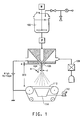
FIG. 1 is an illustration of the prior art electroblowing apparatus. -
FIG. 2 is a schematic of a process and apparatus according to the present invention. - Reference will now be made in detail to the presently preferred embodiments of the invention, examples of which are illustrated in the accompanying drawings. Throughout the drawings, like reference characters are used to designate like elements.
- An electroblowing process for forming fibrous web is disclosed in
PCT publication number WO 03/080905A Fig. 1 ), corresponding toU.S. Serial No. 10/477,882, filed November 19, 2003 - In the process of the present invention, referring to
Figure 2 , according to one embodiment of the invention, a polymer stream comprising a polymer and a solvent, or a polymer melt, is fed from a storage tank, or in the case of a polymer melt from anextruder 100 to a spinning nozzle 104 (also referred to as a "die") located in aspinneret 102 through which the polymer stream is discharged. The polymer stream passes through an electric field generated between spinneret 102 andelectrodes spinneret 102. Compressed gas, which may optionally be heated or cooled in agas temperature controller 108, is issued fromgas nozzles 106 disposed adjacent to or peripherally to the spinningnozzle 104. The gas is directed generally in the direction of the polymer stream flow, in a forwarding gas stream which forward the newly issued polymer stream and aids in the formation of the fibrous web. - While not wishing to be bound by theory, it is believed that the forwarding gas stream provides the majority of the forwarding forces in the initial stages of drawing of the fibers from the issued polymer stream and in the case of polymer solution, simultaneously strips away the mass boundary layer along the individual fiber surface thereby greatly increasing the diffusion rate of solvent from the polymer solution in the form of gas during the formation of the fibrous web.
- At some point, the local electric field around polymer stream is of sufficient strength that the electrical force becomes the dominant drawing force which ultimately draws individual fibers from the polymer stream to diameters measured in the hundreds of nanometers or less.
- It is believed that the angular geometry of the tip of the
spinning nozzle 104, also referred to as the "die tip," creates an intense electric field in the three-dimensional space surrounding the tip which causes charge to be imparted to the polymer stream. The die tip may be in the form of a capillary of any desired cross-sectional shape, or in the form of a linear array of such capillaries. In the embodiment in which the die tip is an angular beam containing a linear capillary array of spinning nozzles, the forwarding gas stream is issued fromgas nozzles 106 on each side of thespinneret 102. The gas nozzles are in the form of slots formed between elongated knife edges, one on each side of thespinneret 102, along the length of the linear capillary array, and thespinneret 102. Alternately, in the embodiment in which the die tip is in the form of a single capillary, thegas nozzle 106 may be in the form of a circumferential slot surrounding thespinneret 102. Thegas nozzles 106 are directed toward the spinning nozzle, generally in the direction of the polymer stream flow. The angular die tip, and therefore the spinning nozzle(s), is positioned such that it extends beyond the end of the spinneret and gas nozzles a distance "e" (Fig. 2 ). It is believed that the electric field combined with the charge on the polymer stream provides spreading forces which act on the fibers and fibrils formed therein, causing the web to be better dispersed and providing for very uniform web laydown on the collection surface of the collector. - Advantageously, the polymer solution is electrically conductive. Examples of polymers for use in the invention may include polyimide, nylon, polyaramide, polybenzimidazole, polyetherimide, polyacrylonitrile, PET (polyethylene terephthalate), polypropylene, polyaniline, polyethylene oxide, PEN (polyethylene naphthalate), PBT (polybutylene terephthalate), SBR (styrene butadiene rubber), polystyrene, PVC (polyvinyl chloride), polyvinyl alcohol, PVDF (polyvinylidene fluoride), polyvinyl butylene and copolymer or derivative compounds thereof. The polymer solution is prepared by selecting a solvent suitable to dissolve the polymer. The polymer solution can be mixed with additives including any resin compatible with an associated polymer, plasticizer, ultraviolet ray stabilizer, crosslink agent, curing agent, reaction initiator, electrical dopant, etc. Any polymer solution known to be suitable for use in a conventional electrospinning process may be used in the process of the invention.
- In another embodiment of the invention, the polymer stream fed to the spin pack and discharged through the nozzle in the spinneret is a polymer melt. Any polymer known to be suitable for use in a melt electrospinning process may be used in the process in the form of a polymer melt.
- Polymer melts and polymer-solvent combinations suitable for use in the process are disclosed in Z. M. Huang et al., Composites Science and Technology, volume 63 (2003), pages 2226-2230.
- Advantageously, the polymer discharge pressure is in the range of about 0.01 kg/cm2 to about 200 kg/cm2, more advantageously in the range of about 0.1 kg/cm2 to about 20 kg/cm2, and the polymer stream throughput per hole is in the range of about 0.1 cc/min to about 15 cc/min.
- The velocity of the compressed gas issued from
gas nozzles 106 is advantageously between about 10 and about 20,000 m/min, and more advantageously between about 100 and about 3,000 m/min. - After the polymer stream exits the spinning
nozzle 104 it passes byelectrodes Fig. 2 . These electrodes can be combined into one unit as a ring-shaped electrode or kept separate as bars. Whereas a ring-shaped electrode can be used for one or more spinning nozzle, bar electrodes extending substantially the entire length of the spinning beam and/or the capillary array, can be used for a beam containing a linear array of spinning nozzle. The distance between the spinning nozzle and the electrode (also referred to as the "die to electrode distance" or "DED") is in the range of about 0.01 to about 100 cm, and more advantageously in the range of about 0.1 to about 25 cm. The electrode can also be placed between the spinning nozzle and the spinneret within a distance "e" (Fig. 2 ), wherein the distance from the spinning nozzle to the collector is less than the distance from the electrode to the collector. However, this embodiment provides a less effective electric field than the embodiment of having the electrode located after spinning nozzle. By applying the voltage to the spinneret, the electrode is grounded. This voltage differential can have a positive or negative polarity with respect to the ground potential. In one embodiment, the spinneret and the electrode can have the same voltage but with different polarities. The voltage differential between the electrode and the spinneret is in the range of about 1 to about 100 kV, and even in the range of about 2 to about 50 kV, and even as low as about 2 to about 30 kV. The process of the invention allows for the use of lower voltage due to a shorter distance between the spinneret and the electrode versus a longer distance between the spinneret and the collector as described above. - Located a distance below the
spinneret 102 is a collector for collecting the fibrous web produced. InFig. 2 , the collector comprises a movingbelt 110 onto which the fibrous web is collected, and can include a porous fibrous scrim which is moving on said moving belt, onto which the fibrous web formed by the present process is deposited. Thebelt 110 is advantageously made from a porous material such as a metal screen so that a vacuum can be drawn from beneath the belt throughvacuum chamber 114 from the inlet ofblower 112. In this embodiment of the invention, the collection belt is grounded. The collected fibrous web of nanofibers is sent to a wind-up roll, not shown. - It has been found that the distance between the spinneret and the collection surface (also referred to as the "die to collector distance" or "DCD"; illustrated in
Fig. 2 ) is in the range of about 1 to about 200 cm, and more advantageously in the range of about 10 to about 50 cm. - It has further been found that when the tip of the spinning nozzle or die tip protrudes from the spinneret by a distance e (
Fig. 2 ), such that the distance between the nozzle and the collection surface is less than the distance between the spinneret and the collection surface, a more uniform electric field results. Not wishing to be bound by theory, it is believed that this is because the protruding nozzle establishes a sharp edge or point in space which concentrates the electric field. - Poly(ethylene oxide) (PEO), viscosity average molecular weight (Mv) -300,000, available from Sigma-Aldrich, St Louis, MO is dissolved in deionized water to make a 10 % by weight PEO solution. The solution electrical conductivity is measured to be 47 Micro-Siemens/cm using a VWR digital conductivity meter available from VWR Scientific Products (VWR International, Inc., West Chester, PA.). The solution is spun in a single orifice electroblowing apparatus comprising a 26 gauge blunt syringe needle, in a concentric forwarding air jet. The needle tip protrudes 2.5 mm below the conductive face of the spin pack body. A high voltage is applied to the spin pack body and the spin orifice. The PEO solution is directed through a ring-shaped electrode, which is electrically grounded through an ammeter. Suitable process conditions are in the Table, below.
- PEO fibers are formed via this process and are collected on a conductive surface and examined under a scanning electron microscope. Nanofibers are collected having fiber diameters ranging from about 100 to about 700 nanometers.
- The procedure of Example 1 is followed except with a smaller inside diameter electrode, with the electrode located closer to the die tip and with a lower voltage applied to the spinneret. Suitable process conditions are listed in the Table, below. Nanofibers are collected having fiber diameters ranging from about 100 to about 700 nanometers.
- The procedure of Example 2 shows that by decreasing the electrode inside diameter and decreasing the DED, the applied voltage to the spinneret can be reduced and still generate similar sized fibers as Example 1.
- The procedure of Example 2 is repeated except with a slightly higher voltage on the spinneret. Suitable process conditions are listed in the Table, below. Nanofibers are collected having fiber diameters ranging from about 100 to about 700 nanometers.
TABLE Spinning Conditions Ex. 1 Ex. 2 Ex. 3 Throughput (mL/min) 0.5 0.5 0.5 Volumetric Airflow (L/min) 24.5 24.5 24.5 Air Flow Velocity (m/s) 12 12 12 Electrode Inside Diameter (mm) 28.2 22.9 22.9 Die to Electrode Distance (mm) 25.4 12.7 12.7 Polarity negative negative negative Voltage (kV) 30 14 16 Die to Collector Distance (cm) 30 30 30 - A procedure was followed in accordance with
PCT publication number WO 03/080905A - A 22 % by weight solution of nylon 6 (type BS400N obtained from BASF Corporation, Mount Olive, NJ) in formic acid (obtained from Kemira Industrial Chemicals, Helsinki, Finland) was electroblown through a spinneret of 100 mm wide, having 11 nozzles at a throughput rate of 1.5 cc/hole. A forwarding air stream was introduced through air nozzles at a flow rate of 4 scfm (2 liters per second). The air was heated to about 70°C. The distance from the spinneret to the upper surface of the collector was approximately 300 mm. The process ran for about 1 minute.
- Nineteen fibers from the product collected were measured for fiber diameter. The average fiber size was 390 nm with a standard deviation of 85.
- Examples 1-3 demonstrate that the use of an electrode positioned and charged in accordance with the present invention requires less voltage than the method of the prior art to produce nanofibers with similar fiber diameters.
Claims (10)
- An electroblowing process for forming a fibrous web comprising:feeding a polymer stream comprising a polymer and a solvent, or a polymer melt, from a storage tank or an extruder (100) respectively, to a spinning nozzle (104) located in a spinneret (102),issuing an electrically charged polymer stream from the spinning nozzle into a gas stream discharged from gas nozzles (106) disposed adjacent to said spinning nozzleand collecting nanofibers formed from the charged polymer stream on a collector as a fibrous web, characterized bypassing the electrically charged polymer stream by a grounded electrode (140, 142), wherein a voltage is applied to the spinneret such that an electric field is generated between the spinneret and the electrode of sufficient strength to impart said electrical charge to the polymer stream as it issues from the spinning nozzle, wherein said electrode is positioned at a distance of between 0.01 cm to 100 cm from the exit of the spinning nozzle.
- The process of claim 1 wherein the polymer stream is a stream of polymer solution.
- The process of claim 1 wherein the polymer stream is a stream of molten polymer.
- The process of claim 1 wherein the polymer stream is electrically conductive.
- The process of claim 1 wherein the collector is substantially grounded.
- The process of claim 1 wherein a voltage differential between the spinneret and the electrode is in the range of 1 to 100 kV.
- The process of claim 6 wherein the voltage differential between the spinneret and the electrode is in the range of 2 to 50 kV.
- The process of claim 1, wherein the polymer stream is negatively charged.
- The process of claim 1, wherein the polymer stream is positively charged.
- The process of claim 1, wherein the polymer stream exits the spinning nozzle at a throughput per hole in the range of 0.1 cm3/min to 15 cm3/min.
Applications Claiming Priority (2)
| Application Number | Priority Date | Filing Date | Title |
|---|---|---|---|
| US11/023,068 US7585451B2 (en) | 2004-12-27 | 2004-12-27 | Electroblowing web formation process |
| PCT/US2005/047395 WO2006071976A2 (en) | 2004-12-27 | 2005-12-27 | Improved electroblowing web formation process |
Publications (2)
| Publication Number | Publication Date |
|---|---|
| EP1834020A2 EP1834020A2 (en) | 2007-09-19 |
| EP1834020B1 true EP1834020B1 (en) | 2010-12-01 |
Family
ID=36190717
Family Applications (1)
| Application Number | Title | Priority Date | Filing Date |
|---|---|---|---|
| EP05855886A Ceased EP1834020B1 (en) | 2004-12-27 | 2005-12-27 | Improved electroblowing web formation process |
Country Status (8)
| Country | Link |
|---|---|
| US (1) | US7585451B2 (en) |
| EP (1) | EP1834020B1 (en) |
| JP (1) | JP5204493B2 (en) |
| KR (1) | KR101260529B1 (en) |
| CN (1) | CN101137781B (en) |
| BR (1) | BRPI0517589A (en) |
| DE (1) | DE602005025161D1 (en) |
| WO (1) | WO2006071976A2 (en) |
Families Citing this family (34)
| Publication number | Priority date | Publication date | Assignee | Title |
|---|---|---|---|---|
| WO2005096744A2 (en) * | 2004-03-31 | 2005-10-20 | The Regents Of The University Of California | Oriented polymer fibers and methods for fabricating thereof |
| US8808608B2 (en) * | 2004-12-27 | 2014-08-19 | E I Du Pont De Nemours And Company | Electroblowing web formation process |
| US7465159B2 (en) * | 2005-08-17 | 2008-12-16 | E.I. Du Pont De Nemours And Company | Fiber charging apparatus |
| JP3918179B1 (en) * | 2006-07-21 | 2007-05-23 | 廣瀬製紙株式会社 | Method for producing fine fiber assembly |
| US20080105626A1 (en) * | 2006-11-02 | 2008-05-08 | David Charles Jones | Fuel filter |
| US8361365B2 (en) * | 2006-12-20 | 2013-01-29 | E I Du Pont De Nemours And Company | Process for electroblowing a multiple layered sheet |
| KR100890192B1 (en) * | 2007-07-10 | 2009-03-25 | 한국기계연구원 | Nano Fiber Manufacturing Equipment |
| JP5226558B2 (en) * | 2009-02-16 | 2013-07-03 | パナソニック株式会社 | Nanofiber manufacturing apparatus and nanofiber manufacturing method |
| CN105477650A (en) | 2009-03-19 | 2016-04-13 | Emd密理博公司 | Removal of microorganisms from fluid samples using nanofiber filtration media |
| WO2011100743A2 (en) * | 2010-02-15 | 2011-08-18 | Cornell University | Electrospinning apparatus and nanofibers produced therefrom |
| JP5417244B2 (en) * | 2010-04-02 | 2014-02-12 | パナソニック株式会社 | Nanofiber manufacturing apparatus and nanofiber manufacturing method |
| MX360481B (en) | 2010-07-02 | 2018-11-05 | Procter & Gamble | Dissolvable fibrous web structure article comprising active agents. |
| US9623352B2 (en) | 2010-08-10 | 2017-04-18 | Emd Millipore Corporation | Method for retrovirus removal |
| SG10201605328WA (en) | 2011-04-01 | 2016-08-30 | Emd Millipore Corp | Nanofiber containing composite structures |
| JP2015516518A (en) | 2012-03-19 | 2015-06-11 | コーネル・ユニバーシティーCornell University | Charged nanofiber and method for producing the same |
| EP2850067B1 (en) | 2012-05-18 | 2017-08-16 | Sumitomo Dainippon Pharma Co., Ltd. | Carboxylic acid compounds |
| US9090996B2 (en) | 2012-08-15 | 2015-07-28 | E I Du Pont De Nemours And Company | Multizone electroblowing process |
| CZ2012834A3 (en) * | 2012-11-23 | 2013-11-06 | Nafigate Corporation, A.S. | Method of producing nanofibers by electrostatic spinning of polymer solution or polymer melt and apparatus for making the same |
| CN102965743B (en) * | 2012-12-17 | 2016-01-27 | 厦门大学 | A kind of nanofiber low tension spinning equipment with auxiliary electrode |
| US10106915B2 (en) * | 2013-12-18 | 2018-10-23 | Anf Inc. | Electro-spinning type pattern forming apparatus |
| WO2015164227A2 (en) | 2014-04-22 | 2015-10-29 | The Procter & Gamble Company | Compositions in the form of dissolvable solid structures |
| SG11201608399QA (en) | 2014-06-26 | 2016-11-29 | Emd Millipore Corp | Filter structure with enhanced dirt holding capacity |
| KR20170113638A (en) | 2015-04-17 | 2017-10-12 | 이엠디 밀리포어 코포레이션 | A method for purifying a biological material of interest in a sample using nanofiber ultrafiltration membranes operating in tangential flow filtration mode |
| US11827001B2 (en) | 2016-02-25 | 2023-11-28 | Avintiv Specialty Materials Inc. | Nonwoven fabrics with additive enhancing barrier properties |
| US10138574B2 (en) * | 2016-10-17 | 2018-11-27 | Fanavaran Nano-Meghyas Company (Ltd) | Blowing-assisted electrospinning |
| KR101972843B1 (en) * | 2017-03-31 | 2019-04-29 | 한양대학교 산학협력단 | Method for Preparing poly(2-cyano-p-phenylene terephthalamide) Nano-fibers and Carbon Nano-fibers Derived Therefrom |
| WO2019016605A1 (en) | 2017-07-21 | 2019-01-24 | Merck Millipore Ltd | Non-woven fiber membranes |
| CZ2017521A3 (en) * | 2017-09-07 | 2019-04-10 | Technická univerzita v Liberci | A method of producing polymer nanofibres by electric or electrostatic spinning of a polymer solution or melt, a spinning electrode for this method, and a device for the production of polymer nanofibres fitted with at least one such spinning electrode |
| US10391449B2 (en) | 2017-11-08 | 2019-08-27 | Cummins Emission Solutions Inc. | Nanofiber augmented diesel particulate filters |
| CN108456935A (en) * | 2018-05-31 | 2018-08-28 | 苏州大学 | Low pressure device for spinning and low pressure spinning process |
| US12209330B1 (en) * | 2019-07-10 | 2025-01-28 | American Nano Llc | Electrospinning apparatus and methods |
| US12194205B2 (en) | 2020-04-30 | 2025-01-14 | Research Triangle Institute | Multi-layer air filtration media with integrated disinfection capability |
| CN114657649B (en) * | 2020-12-24 | 2025-07-22 | 长胜纺织科技发展(上海)有限公司 | Electrostatic spinning device |
| US20220333274A1 (en) * | 2021-04-20 | 2022-10-20 | Jack L. Skinner | Precisely controlled fiber deposition by electrostatic fields |
Family Cites Families (14)
| Publication number | Priority date | Publication date | Assignee | Title |
|---|---|---|---|---|
| US3387326A (en) * | 1964-06-04 | 1968-06-11 | Du Pont | Apparatus for charging and spreading a web |
| US3319309A (en) * | 1964-06-04 | 1967-05-16 | Du Pont | Charged web collecting apparatus |
| JPH01168953A (en) * | 1987-12-23 | 1989-07-04 | Toray Ind Inc | Nonwoven fiber form and production thereof |
| WO1989009298A1 (en) | 1988-03-21 | 1989-10-05 | Automatik Apparate-Maschinenbau Gmbh | Process and device for producing spunbonded fabrics |
| US5227172A (en) * | 1991-05-14 | 1993-07-13 | Exxon Chemical Patents Inc. | Charged collector apparatus for the production of meltblown electrets |
| US5296172A (en) * | 1992-07-31 | 1994-03-22 | E. I. Du Pont De Nemours And Company | Electrostatic field enhancing process and apparatus for improved web pinning |
| US5498463A (en) * | 1994-03-21 | 1996-03-12 | Kimberly-Clark Corporation | Polyethylene meltblown fabric with barrier properties |
| FR2792656B1 (en) * | 1999-04-23 | 2001-06-01 | Icbt Perfojet Sa | DEVICE FOR PROVIDING THE OPENING AND DISTRIBUTION OF A FILM HARNESS DURING THE PRODUCTION OF A NONWOVEN TEXTILE TABLECLOTH |
| US6641773B2 (en) * | 2001-01-10 | 2003-11-04 | The United States Of America As Represented By The Secretary Of The Army | Electro spinning of submicron diameter polymer filaments |
| EP1377421A4 (en) | 2001-03-20 | 2004-05-26 | Nicast Ltd | POLYMERIC FIBER TUBULAR STRUCTURE WITH INCREASED DEFORMATION RESISTANCE |
| KR100549140B1 (en) * | 2002-03-26 | 2006-02-03 | 이 아이 듀폰 디 네모아 앤드 캄파니 | Ultra-fine nanofiber web manufacturing method by electro-blowing |
| WO2003090805A1 (en) | 2002-04-26 | 2003-11-06 | Menicon Co., Ltd. | Process for production of hydrogel material enhanced in the intake of drugs and permitting sustained release of drugs |
| KR100484320B1 (en) * | 2002-11-08 | 2005-04-20 | 경창산업주식회사 | Parking Brake Lever |
| US7465159B2 (en) | 2005-08-17 | 2008-12-16 | E.I. Du Pont De Nemours And Company | Fiber charging apparatus |
-
2004
- 2004-12-27 US US11/023,068 patent/US7585451B2/en active Active
-
2005
- 2005-12-27 JP JP2007549628A patent/JP5204493B2/en not_active Expired - Fee Related
- 2005-12-27 BR BRPI0517589-5A patent/BRPI0517589A/en not_active IP Right Cessation
- 2005-12-27 KR KR1020077017269A patent/KR101260529B1/en not_active Expired - Fee Related
- 2005-12-27 EP EP05855886A patent/EP1834020B1/en not_active Ceased
- 2005-12-27 DE DE602005025161T patent/DE602005025161D1/de not_active Expired - Lifetime
- 2005-12-27 CN CN2005800486589A patent/CN101137781B/en not_active Expired - Fee Related
- 2005-12-27 WO PCT/US2005/047395 patent/WO2006071976A2/en not_active Ceased
Also Published As
| Publication number | Publication date |
|---|---|
| JP5204493B2 (en) | 2013-06-05 |
| CN101137781A (en) | 2008-03-05 |
| KR20070091220A (en) | 2007-09-07 |
| KR101260529B1 (en) | 2013-05-06 |
| US7585451B2 (en) | 2009-09-08 |
| JP2008525669A (en) | 2008-07-17 |
| US20060138711A1 (en) | 2006-06-29 |
| WO2006071976A2 (en) | 2006-07-06 |
| BRPI0517589A (en) | 2008-10-14 |
| WO2006071976A3 (en) | 2006-11-09 |
| DE602005025161D1 (en) | 2011-01-13 |
| CN101137781B (en) | 2011-05-18 |
| EP1834020A2 (en) | 2007-09-19 |
Similar Documents
| Publication | Publication Date | Title |
|---|---|---|
| US7585451B2 (en) | Electroblowing web formation process | |
| EP1841903B1 (en) | Electroblowing web formation process | |
| US7582247B2 (en) | Electroblowing fiber spinning process | |
| US20060012084A1 (en) | Electroblowing web formation process | |
| EP2390388B1 (en) | Improved fiber charging apparatus | |
| JP4047286B2 (en) | Nanofiber web manufacturing method and manufacturing apparatus | |
| KR20250075072A (en) | Melt blown electro spinning device for manufacturing of ultra fine and nano fiber nonwoven fabrics |
Legal Events
| Date | Code | Title | Description |
|---|---|---|---|
| PUAI | Public reference made under article 153(3) epc to a published international application that has entered the european phase |
Free format text: ORIGINAL CODE: 0009012 |
|
| 17P | Request for examination filed |
Effective date: 20070705 |
|
| AK | Designated contracting states |
Kind code of ref document: A2 Designated state(s): DE FR GB |
|
| RBV | Designated contracting states (corrected) |
Designated state(s): DE FR GB |
|
| DAX | Request for extension of the european patent (deleted) | ||
| 17Q | First examination report despatched |
Effective date: 20081007 |
|
| GRAP | Despatch of communication of intention to grant a patent |
Free format text: ORIGINAL CODE: EPIDOSNIGR1 |
|
| GRAS | Grant fee paid |
Free format text: ORIGINAL CODE: EPIDOSNIGR3 |
|
| GRAA | (expected) grant |
Free format text: ORIGINAL CODE: 0009210 |
|
| AK | Designated contracting states |
Kind code of ref document: B1 Designated state(s): DE FR GB |
|
| REG | Reference to a national code |
Ref country code: GB Ref legal event code: FG4D |
|
| REF | Corresponds to: |
Ref document number: 602005025161 Country of ref document: DE Date of ref document: 20110113 Kind code of ref document: P |
|
| PLBE | No opposition filed within time limit |
Free format text: ORIGINAL CODE: 0009261 |
|
| STAA | Information on the status of an ep patent application or granted ep patent |
Free format text: STATUS: NO OPPOSITION FILED WITHIN TIME LIMIT |
|
| 26N | No opposition filed |
Effective date: 20110902 |
|
| REG | Reference to a national code |
Ref country code: DE Ref legal event code: R097 Ref document number: 602005025161 Country of ref document: DE Effective date: 20110902 |
|
| REG | Reference to a national code |
Ref country code: FR Ref legal event code: PLFP Year of fee payment: 11 |
|
| REG | Reference to a national code |
Ref country code: FR Ref legal event code: PLFP Year of fee payment: 12 |
|
| REG | Reference to a national code |
Ref country code: FR Ref legal event code: PLFP Year of fee payment: 13 |
|
| REG | Reference to a national code |
Ref country code: DE Ref legal event code: R081 Ref document number: 602005025161 Country of ref document: DE Owner name: DUPONT SAFETY & CONSTRUCTION, INC., WILMINGTON, US Free format text: FORMER OWNER: E.I. DUPONT DE NEMOURS AND CO., WILMINGTON, DEL., US |
|
| REG | Reference to a national code |
Ref country code: GB Ref legal event code: 732E Free format text: REGISTERED BETWEEN 20221027 AND 20221102 |
|
| PGFP | Annual fee paid to national office [announced via postgrant information from national office to epo] |
Ref country code: GB Payment date: 20221103 Year of fee payment: 18 Ref country code: FR Payment date: 20221110 Year of fee payment: 18 Ref country code: DE Payment date: 20220622 Year of fee payment: 18 |
|
| P01 | Opt-out of the competence of the unified patent court (upc) registered |
Effective date: 20230528 |
|
| REG | Reference to a national code |
Ref country code: DE Ref legal event code: R119 Ref document number: 602005025161 Country of ref document: DE |
|
| GBPC | Gb: european patent ceased through non-payment of renewal fee |
Effective date: 20231227 |
|
| PG25 | Lapsed in a contracting state [announced via postgrant information from national office to epo] |
Ref country code: DE Free format text: LAPSE BECAUSE OF NON-PAYMENT OF DUE FEES Effective date: 20240702 |
|
| PG25 | Lapsed in a contracting state [announced via postgrant information from national office to epo] |
Ref country code: GB Free format text: LAPSE BECAUSE OF NON-PAYMENT OF DUE FEES Effective date: 20231227 |
|
| PG25 | Lapsed in a contracting state [announced via postgrant information from national office to epo] |
Ref country code: FR Free format text: LAPSE BECAUSE OF NON-PAYMENT OF DUE FEES Effective date: 20231231 |
|
| PG25 | Lapsed in a contracting state [announced via postgrant information from national office to epo] |
Ref country code: GB Free format text: LAPSE BECAUSE OF NON-PAYMENT OF DUE FEES Effective date: 20231227 Ref country code: FR Free format text: LAPSE BECAUSE OF NON-PAYMENT OF DUE FEES Effective date: 20231231 Ref country code: DE Free format text: LAPSE BECAUSE OF NON-PAYMENT OF DUE FEES Effective date: 20240702 |