EP1833280A2 - Voice coil bobbin and speaker system - Google Patents
Voice coil bobbin and speaker system Download PDFInfo
- Publication number
- EP1833280A2 EP1833280A2 EP07004796A EP07004796A EP1833280A2 EP 1833280 A2 EP1833280 A2 EP 1833280A2 EP 07004796 A EP07004796 A EP 07004796A EP 07004796 A EP07004796 A EP 07004796A EP 1833280 A2 EP1833280 A2 EP 1833280A2
- Authority
- EP
- European Patent Office
- Prior art keywords
- voice coil
- coil bobbin
- main body
- layer
- bobbin
- Prior art date
- Legal status (The legal status is an assumption and is not a legal conclusion. Google has not performed a legal analysis and makes no representation as to the accuracy of the status listed.)
- Withdrawn
Links
Images



Classifications
-
- H—ELECTRICITY
- H04—ELECTRIC COMMUNICATION TECHNIQUE
- H04R—LOUDSPEAKERS, MICROPHONES, GRAMOPHONE PICK-UPS OR LIKE ACOUSTIC ELECTROMECHANICAL TRANSDUCERS; ELECTRIC HEARING AIDS; PUBLIC ADDRESS SYSTEMS
- H04R9/00—Transducers of moving-coil, moving-strip, or moving-wire type
- H04R9/02—Details
- H04R9/04—Construction, mounting, or centering of coil
- H04R9/046—Construction
-
- H—ELECTRICITY
- H04—ELECTRIC COMMUNICATION TECHNIQUE
- H04R—LOUDSPEAKERS, MICROPHONES, GRAMOPHONE PICK-UPS OR LIKE ACOUSTIC ELECTROMECHANICAL TRANSDUCERS; ELECTRIC HEARING AIDS; PUBLIC ADDRESS SYSTEMS
- H04R31/00—Apparatus or processes specially adapted for the manufacture of transducers or diaphragms therefor
-
- H—ELECTRICITY
- H04—ELECTRIC COMMUNICATION TECHNIQUE
- H04R—LOUDSPEAKERS, MICROPHONES, GRAMOPHONE PICK-UPS OR LIKE ACOUSTIC ELECTROMECHANICAL TRANSDUCERS; ELECTRIC HEARING AIDS; PUBLIC ADDRESS SYSTEMS
- H04R2209/00—Details of transducers of the moving-coil, moving-strip, or moving-wire type covered by H04R9/00 but not provided for in any of its subgroups
- H04R2209/027—Electrical or mechanical reduction of yoke vibration
Definitions
- the present invention relates to a voice coil bobbin and a speaker system.
- Electric/acoustic conversion devices such as microphones and speakers are well known.
- One example of such devices which convert electrical signals into acoustic signals is a commonly known speaker system with a cone-shaped diaphragm (see, for example, Japanese Patent Application Laid-Open Publication No. 2005-277561 ).
- This speaker system includes an annular magnetic circuit made up of a plate, a magnet, and a yoke, and arranged at the lower end of an annular speaker frame. High-density magnetic flux is formed in the magnetic gap between the yoke and the plate of the magnetic circuit.
- a voice coil is wound around a tubular voice coil bobbin such that it can vibrate along the axial direction. The front side edge of this voice coil bobbin is secured to the center hole of the cone-shaped diaphragm, and the outer periphery of the diaphragm is secured to the speaker frame via a surround.
- the voice coil bobbin is required to be able to transmit a motive force which is generated in the voice coil by the input of an audio signal precisely to the cone-shaped diaphragm. Accordingly, it is required to be lightweight for high efficiency transmission, and to have a high specific modulus of elasticity so that it can prevent deformation which may be caused by the vibration, and high internal loss so that it can attenuate unwanted vibration. Paper has been commonly used as the material which satisfies these requirements because paper is low in density and has appropriate rigidity, and also it is inexpensive. Other materials have also been used, such as foils of metals (e.g. aluminum or duralumin), or resin films (e.g. polyimide).
- the voice coil bobbin In high power speakers, a relatively large drive current is inputted to the voice coil to generate a large motive force, and therefore the voice coil bobbin is required to have high rigidity, and also high internal loss to attenuate unwanted vibration in the high frequency range.
- these physical properties are sometimes contradictory and cannot be achieved at the same time depending on the material of the bobbin, and if the voice coil bobbin is made of a single material, it is technically difficult to satisfy both of these requirements.
- one aspect of the present invention is a voice coil bobbin which transmits a motive force from a voice coil wound around the bobbin to a speaker diaphragm, including a main body, a reinforcement layer formed on a surface side of the main body, and a middle layer formed between the main body and the reinforcement layer and made of a material which has a lower density than the main body and the reinforcement layer.
- Another aspect of the present invention is a speaker system in which a voice coil is wound around a voice coil bobbin and positioned in a magnetic gap of a magnetic circuit, and a motive force from the voice coil is transmitted to a speaker diaphragm, the voice coil bobbin including a main body, a reinforcement layer formed on a surface side of the main body, and a middle layer formed between the main body and the reinforcement layer and made of a material which has a lower density than the main body and the reinforcement layer.
- a speaker system includes a voice coil bobbin for transmitting a motive force from the voice coil wound around the bobbin to a speaker diaphragm.
- the voice coil is arranged in a magnetic gap of a magnetic circuit.
- the outer peripheral edge of the diaphragm is supported by, for example, a speaker frame.
- the voice coil bobbin includes a main body, a reinforcement layer on the surface side of the main body, and a middle layer formed between them and made of a material which has a lower density than the reinforcement layer and the main body.
- the middle layer includes a non-woven cloth made of an organic material.
- the middle layer should preferably have a smaller specific modulus of elasticity than the main body and the reinforcement layer.
- the middle layer should preferably have a higher internal loss than the main body and the reinforcement layer.
- the middle layer includes a non-woven cloth made of an aramid organic material.
- the voice coil bobbin of this speaker system has a triple-layer structure with the main body, middle layer, and reinforcement layer with the middle layer being made of a material which has a lower density than the reinforcement layer and the main body, for example an organic non-woven cloth, the voice coil bobbin has high rigidity and high internal loss due to its enhanced structural strength. Thereby, the speaker system incorporating this voice coil bobbin is capable of reproducing high-quality sound.
- Fig. 1 is a cross sectional view of a speaker system according to one embodiment of the invention.
- Fig. 2 is a front view of the speaker system of Fig. 1.
- Fig. 3 is a perspective view of the voice coil in the speaker system of Fig. 1.
- This speaker system 1 of the embodiment includes a magnetic circuit 14 made up of a yoke 11, a magnet 12, and a plate 13.
- the yoke 11 is positioned in the center, the ring-like magnet 12 is arranged around the yoke 11, and the ring-like plate 13 is arranged upon the magnet 12.
- a magnetic gap 15 is formed between the outer circumference of the yoke 11 and the inner circumference of the ring-like magnet 12.
- the magnet 12 can either be a permanent magnet or an electromagnet.
- a voice coil 17 is wound around a voice coil bobbin 16 and positioned in the magnetic gap 15 such that it can vibrate in the axial direction. Near the upper end of the voice coil bobbin 16 is attached to the center hole of a substantially conical speaker diaphragm (diaphragm) 18. A cap 19 is provided on an upper end of the voice coil bobbin 16 or near the center of the diaphragm 18.
- the voice coil bobbin 16 includes one or more apertures 16A which are provided for controlling the pressure inside the cap 19 and the voice coil bobbin 16 and for ensuring smooth movement of the bobbin 16.
- the side and the back of the magnetic circuit 14 are supported by a frame 20.
- the frame 20 includes a plurality of arms 21 radially extending from near the side of the magnetic circuit 14 toward the front.
- a speaker terminal 22 is attached halfway on one of the arms 21.
- the voice coil 17 is electrically connected to the speaker terminal 22 through a lead wire 23 as shown in Fig. 3.
- an annular damper holder (support holder) 25 is provided halfway on the arms 21 .
- a damper 24 is provided between this damper holder 25 and the voice coil bobbin 16 so as to support the bobbin 16 precisely in position in the magnetic gap 15.
- the damper 24 is elastic so that it can smoothly follow the vibration of the voice coil bobbin 16 along the axial direction.
- the outer peripheral edge of the cone-shaped diaphragm 18 is supported on the distal ends 21 a of the arms 21 of the frame 20 via a surround 18a such that the diaphragm can vibrate.
- the damper holder 25 is secured to the plate 13 with fixing members such as bolts 252.
- the damper holder 25 makes contact with the frame 20 at projections 251 which can be formed preferably at three or more equally spaced locations on either one or both of the damper holder 25 and the frame 20.
- This connection structure using the projections 251 induces relative movements between the damper 24 and the frame 20 in reverse phases and thereby attenuates unwanted resonances in the midrange.
- Fig. 4 is a partially cut view of the voice coil bobbin of Fig. 3 given in explanation of its multi-layer structure.
- Fig. 5A is a cross sectional view of the voice coil bobbin of Fig. 3
- Fig. 5B is a cross sectional view of the bobbin illustrating its multi-layer structure.
- the voice coil bobbin 16 is formed cylindrical to have a generally circular or oval cross section.
- the voice coil bobbin 16 according to this embodiment includes a main body (main part) 161, a middle layer (middle part) 162, and a reinforcement layer (reinforcement part) 163 as shown in Fig. 3 to Fig. 5B.
- the main part 161 has the reinforcement part 163 on a surface side thereof, and the middle part 162 which contains non-woven cloth is interposed between the main part 161 and the reinforcement part 163.
- the examples of materials for the main part 161 include organic fibers, inorganic fibers, and metal. More specifically, the main part 161 of the bobbin may be made of any of glass fibers impregnated with a resin such as a phenolic or polyimide resin, foil of metal such as aluminum or duralumin, and film of resin such as polyimide.
- a resin such as a phenolic or polyimide resin
- foil of metal such as aluminum or duralumin
- film of resin such as polyimide.
- the examples of materials for the reinforcement part 163 include organic fibers, inorganic fibers, and metal. More specifically, the reinforcement part 163 of the bobbin may be made of any of glass fibers impregnated with a resin such as a phenolic or polyimide resin, foil of metal such as aluminum or duralumin, and film of resin such as polyimide.
- a resin such as a phenolic or polyimide resin
- foil of metal such as aluminum or duralumin
- film of resin such as polyimide
- the middle part 162 is made of a material which has a lower density than the reinforcement part 163 and the main part 161.
- the material should preferably have a smaller specific modulus of elasticity than one or both of the main part 161 and the reinforcement part 163.
- the material should preferably have a higher internal loss than one or both of the main part 161 and the reinforcement part 163.
- This embodiment uses a non-woven cloth made of an organic material such as aramid fibers for the middle part 162.
- Aramid fibers are strong and highly elastic aromatic polyamide fibers.
- the middle part 162 may be made of an inorganic non-woven cloth.
- the voice coil bobbin 16 of this embodiment has a triple-layer structure consisting of the main part 161, middle part 162, and reinforcement part 163, with a core part 16a and the voice coil 17 wound around the core part at the lower end as shown in Fig. 5B.
- the bobbin 16 has a single-layer structure made of the main part 161 only in the core part 16a at the lower end, where the voice coil 17 is wound around.
- Fig. 6 is an enlarged cross sectional view of the voice coil bobbin and its vicinity in the speaker system 1 of Fig. 1.
- the inner peripheral edge of the diaphragm 18 is secured using an adhesive 26 to the reinforcement part 163 which is formed on the middle part 162 of the bobbin.
- the inner peripheral edge of the damper 24 is also secured to the reinforcement part 163 using an adhesive 26.
- the voice coil bobbin 16 includes the main body (main part) 161, the middle layer (middle part) 162, and the reinforcement layer (reinforcement part) 163 provided on the surface side of the main part 161, with the middle part 162 being formed between the main part 161 and the reinforcement part 163 and made of a material which has a lower density than the other two parts, such as an organic non-woven cloth, the voice coil bobbin 16 has high rigidity and internal loss due to its enhanced structural strength.
- This voice coil bobbin 16 is produced, for example, by heat and pressure molding with the middle part 162 of aramid non-woven cloth and the reinforcement part 163 of polyimide resin-impregnated glass fibers laminated upon the tubular main part 161 which is pre-formed from phenolic resin-impregnated glass fibers.
- An input of a signal current from the speaker terminal 22 through the lead wire 23 to the voice coil 17 generates a magnetic force in the coil 17, which, together with the action of the magnetic circuit 14, drives the voice coil bobbin 16 to vibrate in the axial direction.
- This motive force is transmitted from the main part 161, at which the bobbin 16 is secured, through the middle part 162 and the reinforcement part 163 to the diaphragm 18 and vibrates the diaphragm 18. As the motive force is thus transmitted through the middle part 162, unwanted vibration is reduced.
- the inventor of the present invention has measured the acoustic properties such as internal loss and specific modulus of elasticity of the voice coil bobbin 16 according to one embodiment of the present invention which has the triple-layer structure of the main part 161, middle part 162, and reinforcement part 163, and of various other voice coil bobbins for comparison, to compare the respective performances of the bobbins 16.
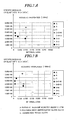
- Fig. 7A and Fig. 7B are graphs illustrating the results shown in Table 1. In these graphs, the horizontal axis represents the internal loss and the vertical axis represents the specific modulus of elasticity (E/p [m 2 /s 2 ]).
- Comparative Example 1 is a single-layer voice coil bobbin shown in Fig. 8A made of phenolic resin-impregnated glass fibers (A).
- Comparative Example 2 is a single-layer voice coil bobbin shown in Fig. 8A made of polyimide resin-impregnated glass fibers (B).
- Comparative Example 3 is a single-layer voice coil bobbin shown in Fig. 8A made of aramid non-woven cloth (C).
- the voice coil bobbin 16 of the present invention is a triple-layer bobbin shown in Fig. 8C, including the main part 161 made of phenolic resin-impregnated glass fibers (A), the middle part 162 made of aramid non-woven cloth (C), and the reinforcement part 163 made of polyimide resin-impregnated glass fibers (B).
- Comparative Example 4 is a triple-layer bobbin shown in Fig. 8C, including the main part 161 made of phenolic resin-impregnated glass fibers (A), the middle part 162 made of polyimide resin-impregnated glass fibers (B), and the reinforcement part 163 made of aramid non-woven cloth (C).
- Comparative Example 5 is a double-layer bobbin shown in Fig. 8B, including the main part 161 made of phenolic resin-impregnated glass fibers (A), and the reinforcement part 163 made of polyimide resin-impregnated glass fibers (B).
- Comparative Example 6 is a double-layer bobbin shown in Fig. 8B, including the main part 161 made of phenolic resin-impregnated glass fibers (A) and aramid non-woven cloth (C) provided around the main part.
- Comparative Example 7 is a double-layer bobbin shown in Fig. 8B, including the main part 161 made of polyimide resin-impregnated glass fibers (B), and the reinforcement part 163 made of aramid non-woven cloth (C).
- the middle part 162 is made of aramid non-woven cloth (C), which has an internal loss of about ten times larger than that of the phenolic or polyimide resin-impregnated glass fibers (A) or (B) of the main part 161 and the reinforcement part 163, and which has a specific modulus of elasticity of about four to five times smaller than that of the glass fibers (A) and (B). Therefore, the voice coil bobbin 16 exhibited higher internal loss and specific modulus of elasticity as compared to the voice coil bobbins of Comparative Examples 1 and 2, which are made of a single material of either (A) or (B).
- the voice coil bobbin 16 of the present invention has higher specific modulus of elasticity and substantially equal internal loss as compared to the double-layer voice coil bobbins of Comparative Examples 5 to 7.
- the voice coil bobbin 16 of the present invention has higher internal loss and specific modulus of elasticity as compared to the triple-layer voice coil bobbin of Comparative Example 4.
- the upper right region of the graphs shown in Fig. 7A and Fig. 7B represents high specific modulus of elasticity and high internal loss of the bobbin material.
- the voice coil bobbin 16 of the present invention which has the triple-layer structure of the main part 161 made of phenolic resin-impregnated glass fibers (A), middle part 162 made of aramid non-woven cloth (C), and reinforcement part 163 made of polyimide resin-impregnated glass fibers (B), exhibited better properties than the other examples which are made of a single material or a combination of two materials.
- the present invention is obviously not limited to the above example of the embodiment. Other combinations of materials as noted in the description of the embodiment of the invention are possible. Also, the dome-shaped diaphragm of the invention can be applied to other electronic/acoustic conversion devices such as microphones.
- diaphragm 18 Various other shapes can be adopted for the diaphragm 18, such as a curved cone, a flat cone, a parabolic cone, an oval cone, a circular cone, and the like.
- the diaphragm 18 used in the embodiment described above has a corrugation on a surface thereof, but this is not an absolute requirement.
- the voice coil bobbin 16 of the invention is a bobbin which transmits a motive force from the voice coil wound around the bobbin to the speaker diaphragm, including a main part (main body) 161, a reinforcement part (reinforcement layer) 163 provided on the surface side of the main part, and a middle part (middle layer) 162 sandwiched between them and made of a material which has a lower density than the other two parts.
- a simple-design, high-rigidity voice coil bobbin with high internal loss is obtained.
- middle part (middle layer) 162 being formed of an organic non-woven cloth, a simple-design, high-rigidity voice coil bobbin with high internal loss can be produced.
Landscapes
- Engineering & Computer Science (AREA)
- Physics & Mathematics (AREA)
- Acoustics & Sound (AREA)
- Signal Processing (AREA)
- Manufacturing & Machinery (AREA)
- Audible-Bandwidth Dynamoelectric Transducers Other Than Pickups (AREA)
Abstract
Description
- The present invention relates to a voice coil bobbin and a speaker system.
- Electric/acoustic conversion devices such as microphones and speakers are well known. One example of such devices which convert electrical signals into acoustic signals is a commonly known speaker system with a cone-shaped diaphragm (see, for example,
Japanese Patent Application Laid-Open Publication No. 2005-277561 - This speaker system includes an annular magnetic circuit made up of a plate, a magnet, and a yoke, and arranged at the lower end of an annular speaker frame. High-density magnetic flux is formed in the magnetic gap between the yoke and the plate of the magnetic circuit. A voice coil is wound around a tubular voice coil bobbin such that it can vibrate along the axial direction. The front side edge of this voice coil bobbin is secured to the center hole of the cone-shaped diaphragm, and the outer periphery of the diaphragm is secured to the speaker frame via a surround.
- The voice coil bobbin is required to be able to transmit a motive force which is generated in the voice coil by the input of an audio signal precisely to the cone-shaped diaphragm. Accordingly, it is required to be lightweight for high efficiency transmission, and to have a high specific modulus of elasticity so that it can prevent deformation which may be caused by the vibration, and high internal loss so that it can attenuate unwanted vibration. Paper has been commonly used as the material which satisfies these requirements because paper is low in density and has appropriate rigidity, and also it is inexpensive. Other materials have also been used, such as foils of metals (e.g. aluminum or duralumin), or resin films (e.g. polyimide).
- In high power speakers, a relatively large drive current is inputted to the voice coil to generate a large motive force, and therefore the voice coil bobbin is required to have high rigidity, and also high internal loss to attenuate unwanted vibration in the high frequency range. However, these physical properties are sometimes contradictory and cannot be achieved at the same time depending on the material of the bobbin, and if the voice coil bobbin is made of a single material, it is technically difficult to satisfy both of these requirements.
- It is an object of the present invention to solve these problems and to provide a simple-design, high-rigidity voice coil bobbin with high internal loss, and a speaker system which can reproduce high-quality sound.
- To achieve the above object, one aspect of the present invention is a voice coil bobbin which transmits a motive force from a voice coil wound around the bobbin to a speaker diaphragm, including a main body, a reinforcement layer formed on a surface side of the main body, and a middle layer formed between the main body and the reinforcement layer and made of a material which has a lower density than the main body and the reinforcement layer.
- Another aspect of the present invention is a speaker system in which a voice coil is wound around a voice coil bobbin and positioned in a magnetic gap of a magnetic circuit, and a motive force from the voice coil is transmitted to a speaker diaphragm, the voice coil bobbin including a main body, a reinforcement layer formed on a surface side of the main body, and a middle layer formed between the main body and the reinforcement layer and made of a material which has a lower density than the main body and the reinforcement layer.
- These and other objects and advantages of the present invention will become clear from the following description with reference to the accompanying drawings, wherein:
- Fig. 1
- is a cross sectional view of a speaker system according to one embodiment of the present invention;
- Fig. 2
- is a front view of the speaker system of Fig. 1;
- Fig. 3
- is a perspective view of the voice coil in the speaker system of Fig. 1;
- Fig. 4
- is a partially cut view of the voice coil bobbin of Fig. 3 given in explanation of its multi-layer structure;
- Fig. 5A
- is a cross sectional view of the voice coil bobbin of Fig. 3, and
- Fig. 5B
- is a cross sectional view of the bobbin illustrating its multilayer structure;
- Fig. 6
- is an enlarged cross sectional view of the voice coil bobbin and its vicinity in the speaker system of Fig. 1;
- Fig. 7A and Fig. 7B
- are graphs showing the physical properties of the voice coil bobbin according to one embodiment of the invention and of various other examples, in particular the relationship between the internal loss and the specific modulus of elasticity, when reproducing a 100 Hz and a 1000 Hz audio signal, respectively; and
- Fig. 8A to Fig. 8C
- are enlarged cross sectional views of voice coil bobbins with a single-, a double-, and a triple-layer structure, respectively.
- A speaker system according to one embodiment of the present invention includes a voice coil bobbin for transmitting a motive force from the voice coil wound around the bobbin to a speaker diaphragm. The voice coil is arranged in a magnetic gap of a magnetic circuit. The outer peripheral edge of the diaphragm is supported by, for example, a speaker frame. The voice coil bobbin includes a main body, a reinforcement layer on the surface side of the main body, and a middle layer formed between them and made of a material which has a lower density than the reinforcement layer and the main body.
- Preferably, the middle layer includes a non-woven cloth made of an organic material. Also, the middle layer should preferably have a smaller specific modulus of elasticity than the main body and the reinforcement layer. Furthermore, the middle layer should preferably have a higher internal loss than the main body and the reinforcement layer. Preferably, the middle layer includes a non-woven cloth made of an aramid organic material.
- As the voice coil bobbin of this speaker system has a triple-layer structure with the main body, middle layer, and reinforcement layer with the middle layer being made of a material which has a lower density than the reinforcement layer and the main body, for example an organic non-woven cloth, the voice coil bobbin has high rigidity and high internal loss due to its enhanced structural strength. Thereby, the speaker system incorporating this voice coil bobbin is capable of reproducing high-quality sound.
- One specific example of the voice coil bobbin and the speaker system including the bobbin of the present invention will be hereinafter described in detail with reference to the drawings.
- Fig. 1 is a cross sectional view of a speaker system according to one embodiment of the invention. Fig. 2 is a front view of the speaker system of Fig. 1. Fig. 3 is a perspective view of the voice coil in the speaker system of Fig. 1.
- This
speaker system 1 of the embodiment includes amagnetic circuit 14 made up of ayoke 11, amagnet 12, and aplate 13. In particular, as shown in Fig. 1, theyoke 11 is positioned in the center, the ring-like magnet 12 is arranged around theyoke 11, and the ring-like plate 13 is arranged upon themagnet 12. Amagnetic gap 15 is formed between the outer circumference of theyoke 11 and the inner circumference of the ring-like magnet 12. Themagnet 12 can either be a permanent magnet or an electromagnet. - A
voice coil 17 is wound around avoice coil bobbin 16 and positioned in themagnetic gap 15 such that it can vibrate in the axial direction. Near the upper end of thevoice coil bobbin 16 is attached to the center hole of a substantially conical speaker diaphragm (diaphragm) 18. Acap 19 is provided on an upper end of thevoice coil bobbin 16 or near the center of thediaphragm 18. Thevoice coil bobbin 16 includes one ormore apertures 16A which are provided for controlling the pressure inside thecap 19 and thevoice coil bobbin 16 and for ensuring smooth movement of thebobbin 16. - The side and the back of the
magnetic circuit 14 are supported by aframe 20. Theframe 20 includes a plurality ofarms 21 radially extending from near the side of themagnetic circuit 14 toward the front. Aspeaker terminal 22 is attached halfway on one of thearms 21. Thevoice coil 17 is electrically connected to thespeaker terminal 22 through alead wire 23 as shown in Fig. 3. - Also halfway on the
arms 21 is formed an annular damper holder (support holder) 25. Adamper 24 is provided between thisdamper holder 25 and thevoice coil bobbin 16 so as to support thebobbin 16 precisely in position in themagnetic gap 15. Thedamper 24 is elastic so that it can smoothly follow the vibration of thevoice coil bobbin 16 along the axial direction. The outer peripheral edge of the cone-shapeddiaphragm 18 is supported on the distal ends 21 a of thearms 21 of theframe 20 via asurround 18a such that the diaphragm can vibrate. - The
damper holder 25 is secured to theplate 13 with fixing members such asbolts 252. Thedamper holder 25 makes contact with theframe 20 atprojections 251 which can be formed preferably at three or more equally spaced locations on either one or both of thedamper holder 25 and theframe 20. This connection structure using theprojections 251 induces relative movements between thedamper 24 and theframe 20 in reverse phases and thereby attenuates unwanted resonances in the midrange. - An input of a signal current from the
speaker terminal 22 through thelead wire 23 to thevoice coil 17 generates a magnetic force, which, together with the action of themagnetic circuit 14, causes thevoice coil bobbin 16 to vibrate in the axial direction. Thus thediaphragm 18 vibrates back and forth and produces sound as a longitudinal wave which travels through gases or liquids. - Next, the
voice coil bobbin 16 and thevoice coil 17 will be described in more detail. Fig. 4 is a partially cut view of the voice coil bobbin of Fig. 3 given in explanation of its multi-layer structure. Fig. 5A is a cross sectional view of the voice coil bobbin of Fig. 3, and Fig. 5B is a cross sectional view of the bobbin illustrating its multi-layer structure. - The
voice coil bobbin 16 is formed cylindrical to have a generally circular or oval cross section. Thevoice coil bobbin 16 according to this embodiment includes a main body (main part) 161, a middle layer (middle part) 162, and a reinforcement layer (reinforcement part) 163 as shown in Fig. 3 to Fig. 5B. Themain part 161 has thereinforcement part 163 on a surface side thereof, and themiddle part 162 which contains non-woven cloth is interposed between themain part 161 and thereinforcement part 163. - The examples of materials for the
main part 161 include organic fibers, inorganic fibers, and metal. More specifically, themain part 161 of the bobbin may be made of any of glass fibers impregnated with a resin such as a phenolic or polyimide resin, foil of metal such as aluminum or duralumin, and film of resin such as polyimide. - The examples of materials for the
reinforcement part 163 include organic fibers, inorganic fibers, and metal. More specifically, thereinforcement part 163 of the bobbin may be made of any of glass fibers impregnated with a resin such as a phenolic or polyimide resin, foil of metal such as aluminum or duralumin, and film of resin such as polyimide. - The
middle part 162 is made of a material which has a lower density than thereinforcement part 163 and themain part 161. The material should preferably have a smaller specific modulus of elasticity than one or both of themain part 161 and thereinforcement part 163. Furthermore, the material should preferably have a higher internal loss than one or both of themain part 161 and thereinforcement part 163. This embodiment uses a non-woven cloth made of an organic material such as aramid fibers for themiddle part 162. Aramid fibers are strong and highly elastic aromatic polyamide fibers. Alternatively, themiddle part 162 may be made of an inorganic non-woven cloth. - The
voice coil bobbin 16 of this embodiment has a triple-layer structure consisting of themain part 161,middle part 162, andreinforcement part 163, with acore part 16a and thevoice coil 17 wound around the core part at the lower end as shown in Fig. 5B. Namely, as shown, thebobbin 16 has a single-layer structure made of themain part 161 only in thecore part 16a at the lower end, where thevoice coil 17 is wound around. - Fig. 6 is an enlarged cross sectional view of the voice coil bobbin and its vicinity in the
speaker system 1 of Fig. 1. In this embodiment, the inner peripheral edge of thediaphragm 18 is secured using an adhesive 26 to thereinforcement part 163 which is formed on themiddle part 162 of the bobbin. The inner peripheral edge of thedamper 24 is also secured to thereinforcement part 163 using an adhesive 26. - Since the
voice coil bobbin 16 includes the main body (main part) 161, the middle layer (middle part) 162, and the reinforcement layer (reinforcement part) 163 provided on the surface side of themain part 161, with themiddle part 162 being formed between themain part 161 and thereinforcement part 163 and made of a material which has a lower density than the other two parts, such as an organic non-woven cloth, thevoice coil bobbin 16 has high rigidity and internal loss due to its enhanced structural strength. - This
voice coil bobbin 16 is produced, for example, by heat and pressure molding with themiddle part 162 of aramid non-woven cloth and thereinforcement part 163 of polyimide resin-impregnated glass fibers laminated upon the tubularmain part 161 which is pre-formed from phenolic resin-impregnated glass fibers. - An input of a signal current from the
speaker terminal 22 through thelead wire 23 to thevoice coil 17 generates a magnetic force in thecoil 17, which, together with the action of themagnetic circuit 14, drives thevoice coil bobbin 16 to vibrate in the axial direction. This motive force is transmitted from themain part 161, at which thebobbin 16 is secured, through themiddle part 162 and thereinforcement part 163 to thediaphragm 18 and vibrates thediaphragm 18. As the motive force is thus transmitted through themiddle part 162, unwanted vibration is reduced. - The inventor of the present invention has measured the acoustic properties such as internal loss and specific modulus of elasticity of the
voice coil bobbin 16 according to one embodiment of the present invention which has the triple-layer structure of themain part 161,middle part 162, andreinforcement part 163, and of various other voice coil bobbins for comparison, to compare the respective performances of thebobbins 16.TABLE1 MATERIAL THICKNESS t DENSITY ρ YOUNG'S MODULUS E [N/m3] INTERNAL LOSS SPECIFIC MODULUS OF ELASTICITY E/ρ 2 [m2/s2] E/ρ2 [mm] [kg/m'] 100Hz 1000Hz 100Hz 1000Hz 100Hz 1000Hz 100Hz 1000Hz COMPARATIVE EXAMPLE 1 A 0.18 1450 6.92E+09 7.05E+09 0.0157 0.0145 4.77E+06 4.86E+06 3.29E+03 3.35E+03 COMPARATIVE EXAMPLE 2 B 0.19 1460 5.79E+09 6.07E+09 0.0167 0.0157 3.97E+06 4.16E+06 2.72E+03 2.85E+03 COMPARATIVE EXAMPLE 3 C 0.18 710 7.35E+08 9.31E+08 0.2009 0.1567 1.04E+06 1.31E+06 1.46E+03 1.85E+03 EXAMPLE OF THE PRESENT INVENTION A+C+B 0.53 1270 8.28E+09 9.11 E+09 0.1018 0.0740 6.52E+06 7.17E+06 5.13E+03 5.65E+03 COMPARATIVE EXAMPLE 4 A+B+C 0.53 1250 6.92E+09 5.57E+09 0.0761 0.0589 5.54E+06 4.46E+06 4.43E+03 3.56E+03 COMPARATIVE EXAMPLE 5 A+B 0.38 1420 5.16E+09 8.14E+09 0.0340 0.0263 3.63E+06 5.57E+06 2.56E+03 4.04E+03 COMPARATIVE EXAMPLE 6 A+C 0.36 1080 3.70E+09 4.22E+09 0.1045 0.0835 3.43E+06 3.91E+06 3.17E+03 3.62E+03 COMPARATIVE EXAMPLE 7 C+B 0.36 1120 3.40E+09 3.81E+09 0.0976 0.0820 3,04E+06 3.40E+06 2.71E+03 3.04E+03 - For the comparison, voice coil bobbins made of either one or a combination of A) phenolic resin-impregnated glass fibers, B) polyimide resin-impregnated glass fibers, and C) aramid non-woven cloth were produced, and their various properties were measured. The results are shown in Table 1. Fig. 7A and Fig. 7B are graphs illustrating the results shown in Table 1. In these graphs, the horizontal axis represents the internal loss and the vertical axis represents the specific modulus of elasticity (E/p [m2/s2]).
- Comparative Example 1 is a single-layer voice coil bobbin shown in Fig. 8A made of phenolic resin-impregnated glass fibers (A). Comparative Example 2 is a single-layer voice coil bobbin shown in Fig. 8A made of polyimide resin-impregnated glass fibers (B). Comparative Example 3 is a single-layer voice coil bobbin shown in Fig. 8A made of aramid non-woven cloth (C).
- The
voice coil bobbin 16 of the present invention is a triple-layer bobbin shown in Fig. 8C, including themain part 161 made of phenolic resin-impregnated glass fibers (A), themiddle part 162 made of aramid non-woven cloth (C), and thereinforcement part 163 made of polyimide resin-impregnated glass fibers (B). - Comparative Example 4 is a triple-layer bobbin shown in Fig. 8C, including the
main part 161 made of phenolic resin-impregnated glass fibers (A), themiddle part 162 made of polyimide resin-impregnated glass fibers (B), and thereinforcement part 163 made of aramid non-woven cloth (C). - Comparative Example 5 is a double-layer bobbin shown in Fig. 8B, including the
main part 161 made of phenolic resin-impregnated glass fibers (A), and thereinforcement part 163 made of polyimide resin-impregnated glass fibers (B). - Comparative Example 6 is a double-layer bobbin shown in Fig. 8B, including the
main part 161 made of phenolic resin-impregnated glass fibers (A) and aramid non-woven cloth (C) provided around the main part. - Comparative Example 7 is a double-layer bobbin shown in Fig. 8B, including the
main part 161 made of polyimide resin-impregnated glass fibers (B), and thereinforcement part 163 made of aramid non-woven cloth (C). - In the triple-layer structure of the
voice coil bobbin 16 of the present invention, themiddle part 162 is made of aramid non-woven cloth (C), which has an internal loss of about ten times larger than that of the phenolic or polyimide resin-impregnated glass fibers (A) or (B) of themain part 161 and thereinforcement part 163, and which has a specific modulus of elasticity of about four to five times smaller than that of the glass fibers (A) and (B). Therefore, thevoice coil bobbin 16 exhibited higher internal loss and specific modulus of elasticity as compared to the voice coil bobbins of Comparative Examples 1 and 2, which are made of a single material of either (A) or (B). - Also the results showed that the
voice coil bobbin 16 of the present invention has higher specific modulus of elasticity and substantially equal internal loss as compared to the double-layer voice coil bobbins of Comparative Examples 5 to 7. - Furthermore, the results showed that the
voice coil bobbin 16 of the present invention has higher internal loss and specific modulus of elasticity as compared to the triple-layer voice coil bobbin of Comparative Example 4. - The upper right region of the graphs shown in Fig. 7A and Fig. 7B represents high specific modulus of elasticity and high internal loss of the bobbin material. As can be seen, the
voice coil bobbin 16 of the present invention, which has the triple-layer structure of themain part 161 made of phenolic resin-impregnated glass fibers (A),middle part 162 made of aramid non-woven cloth (C), andreinforcement part 163 made of polyimide resin-impregnated glass fibers (B), exhibited better properties than the other examples which are made of a single material or a combination of two materials. - The present invention is obviously not limited to the above example of the embodiment. Other combinations of materials as noted in the description of the embodiment of the invention are possible. Also, the dome-shaped diaphragm of the invention can be applied to other electronic/acoustic conversion devices such as microphones.
- While the embodiment described above uses a magnetic circuit with an internal magnet structure, an external magnet structure can also be adopted.
- Various other shapes can be adopted for the
diaphragm 18, such as a curved cone, a flat cone, a parabolic cone, an oval cone, a circular cone, and the like. Thediaphragm 18 used in the embodiment described above has a corrugation on a surface thereof, but this is not an absolute requirement. - As described above, the
voice coil bobbin 16 of the invention is a bobbin which transmits a motive force from the voice coil wound around the bobbin to the speaker diaphragm, including a main part (main body) 161, a reinforcement part (reinforcement layer) 163 provided on the surface side of the main part, and a middle part (middle layer) 162 sandwiched between them and made of a material which has a lower density than the other two parts. Thus a simple-design, high-rigidity voice coil bobbin with high internal loss is obtained. - With the middle part (middle layer) 162 being formed of an organic non-woven cloth, a simple-design, high-rigidity voice coil bobbin with high internal loss can be produced.
- With this
voice coil bobbin 16 being adopted in a speaker system, in which thevoice coil 17 is wound around thebobbin 16 and positioned in themagnetic gap 15 of themagnetic circuit 14, and a motive force from thevoice coil 17 is transmitted to thediaphragm 18, high-quality sound reproduction is made possible.
Claims (11)
- A voice coil bobbin (16) which is adapted to transmit a motive force from a voice coil (17) wound around the bobbin to a speaker diaphragm (18), comprising:- a main body (161);- a reinforcement layer (163) formed on a surface side of the main body (161); and- a middle layer (162) formed between the main body (161) and the reinforcement layer (163) and made of a material which has a lower density than the main body (161) and the reinforcement layer (163).
- The voice coil bobbin according to claim 1,
wherein the middle layer (162) includes a non-woven cloth made of an organic material. - The voice coil bobbin according to claim 2,
wherein the non-woven cloth is made of an aramid organic material. - The voice coil bobbin according to any of claims 1 to 3,
wherein the main body (161) includes a material selected from a group consisting of organic fibers, inorganic fibers, and metal. - The voice coil bobbin according to any of claims 1 to 4,
wherein the reinforcement layer (163) includes a material selected from a group consisting of organic fibers, inorganic fibers, and metal. - The voice coil bobbin according to any of claims 1 to 5,
wherein the voice coil bobbin (16) is made of the main body (161) only in a core part (16a) around which the voice coil (17) is wound. - The voice coil bobbin according to any of claims 1 to 6,
wherein an inner peripheral part of the speaker diaphragm is secured to the reinforcement layer (163) formed on the middle layer (162) of the voice coil bobbin (16). - The voice coil bobbin according to any of claims 1 to 7,
wherein the middle layer (162) has a smaller specific modulus of elasticity than the main body (161) and the reinforcement layer (163). - The voice coil bobbin according to any of claims 1 to 8,
wherein the middle layer (162) has a higher internal loss than the main body (161) and the reinforcement layer (163). - The voice coil bobbin according to any of claims 1 to 9,
wherein the main body (161) includes glass fibers impregnated with a phenolic resin, the reinforcement layer (163) includes glass fibers impregnated with a polyimide resin, and the middle layer (162) includes a non-woven cloth made of an aramid fiber material. - A speaker system (1) in which a voice coil (17) is wound around a voice coil bobbin (16) and positioned in a magnetic gap (15) of a magnetic circuit (14), and a motive force from the voice coil (17) is transmitted to a speaker diaphragm (18),
comprising a voice coil bobbin (16) according to any of claims 1 to 10.
Applications Claiming Priority (1)
| Application Number | Priority Date | Filing Date | Title |
|---|---|---|---|
| JP2006064068A JP4790452B2 (en) | 2006-03-09 | 2006-03-09 | Voice coil bobbin and speaker device |
Publications (2)
| Publication Number | Publication Date |
|---|---|
| EP1833280A2 true EP1833280A2 (en) | 2007-09-12 |
| EP1833280A3 EP1833280A3 (en) | 2008-02-20 |
Family
ID=38134603
Family Applications (1)
| Application Number | Title | Priority Date | Filing Date |
|---|---|---|---|
| EP07004796A Withdrawn EP1833280A3 (en) | 2006-03-09 | 2007-03-08 | Voice coil bobbin and speaker system |
Country Status (3)
| Country | Link |
|---|---|
| US (1) | US8059857B2 (en) |
| EP (1) | EP1833280A3 (en) |
| JP (1) | JP4790452B2 (en) |
Families Citing this family (8)
| Publication number | Priority date | Publication date | Assignee | Title |
|---|---|---|---|---|
| JP4400439B2 (en) * | 2004-12-14 | 2010-01-20 | パナソニック株式会社 | Speaker |
| JP2009194467A (en) * | 2008-02-12 | 2009-08-27 | Victor Co Of Japan Ltd | Voice coil and speaker |
| KR101062984B1 (en) * | 2009-04-01 | 2011-09-07 | 주식회사 디알하이텍 | Front Bobbin |
| JP2012080481A (en) * | 2010-10-06 | 2012-04-19 | Sony Corp | Speaker unit and active speaker device |
| KR101233063B1 (en) | 2012-04-19 | 2013-02-19 | (주)휴넷플러스 | Method for fabricating nano patterned substrate for high efficiency nitride based light emitting diode |
| TWI767892B (en) * | 2016-11-04 | 2022-06-21 | 香港商比特聯創(控股)有限公司 | Diaphragm for speaker |
| JP2018207265A (en) | 2017-06-02 | 2018-12-27 | アルパイン株式会社 | Loudspeaker |
| US10667059B1 (en) * | 2019-05-07 | 2020-05-26 | Meiloon Industrial Co., Ltd. | Driver structure of thin speaker |
Family Cites Families (21)
| Publication number | Priority date | Publication date | Assignee | Title |
|---|---|---|---|---|
| JPS542651Y2 (en) * | 1973-06-18 | 1979-02-05 | ||
| JPS5516475Y2 (en) * | 1974-11-20 | 1980-04-17 | ||
| JPS607877B2 (en) * | 1978-01-30 | 1985-02-27 | ソニー株式会社 | voice coil bobbin |
| JPS6057797B2 (en) * | 1978-12-05 | 1985-12-17 | 松下電器産業株式会社 | Voice coil for speaker |
| JPS5714280A (en) * | 1980-06-30 | 1982-01-25 | Pioneer Electronic Corp | Voice coil bobbin |
| JPS5734693U (en) * | 1980-07-29 | 1982-02-23 | ||
| JPS623995Y2 (en) * | 1981-01-28 | 1987-01-29 | ||
| JPS623987Y2 (en) * | 1981-02-04 | 1987-01-29 | ||
| JPS57173298A (en) * | 1981-04-16 | 1982-10-25 | Matsushita Electric Ind Co Ltd | Speaker |
| JPS6087600A (en) * | 1983-10-19 | 1985-05-17 | Matsushita Electric Ind Co Ltd | Voice coil for speaker |
| JPS6170491U (en) * | 1984-10-16 | 1986-05-14 | ||
| JPS6368296U (en) * | 1986-10-21 | 1988-05-09 | ||
| JPS6460100A (en) * | 1987-08-31 | 1989-03-07 | Foster Electric Co Ltd | Voice coil bobbin for speaker |
| JP2779633B2 (en) * | 1988-12-27 | 1998-07-23 | フオスター電機株式会社 | Voice coil bobbin for speaker |
| JPH07288894A (en) * | 1995-03-09 | 1995-10-31 | Sony Corp | Voice coil bobbin |
| JP3631548B2 (en) * | 1996-01-04 | 2005-03-23 | 鈴木管紙株式会社 | Voice coil and bobbin |
| JP3823493B2 (en) * | 1997-11-19 | 2006-09-20 | 松下電器産業株式会社 | Voice coil and speaker using the same |
| JP3611096B2 (en) * | 1998-09-21 | 2005-01-19 | オンキヨー株式会社 | Speaker components |
| JP2004336276A (en) * | 2003-05-06 | 2004-11-25 | Pioneer Electronic Corp | Bobbin and reinforcement method of bobbin |
| JP2005244325A (en) * | 2004-02-24 | 2005-09-08 | Pioneer Electronic Corp | Voice coil bobbin and speaker |
| JP4408731B2 (en) | 2004-03-23 | 2010-02-03 | パイオニア株式会社 | Speaker |
-
2006
- 2006-03-09 JP JP2006064068A patent/JP4790452B2/en not_active Expired - Fee Related
-
2007
- 2007-03-08 EP EP07004796A patent/EP1833280A3/en not_active Withdrawn
- 2007-03-09 US US11/716,041 patent/US8059857B2/en not_active Expired - Fee Related
Also Published As
| Publication number | Publication date |
|---|---|
| US8059857B2 (en) | 2011-11-15 |
| JP4790452B2 (en) | 2011-10-12 |
| EP1833280A3 (en) | 2008-02-20 |
| US20070223775A1 (en) | 2007-09-27 |
| JP2007243659A (en) | 2007-09-20 |
Similar Documents
| Publication | Publication Date | Title |
|---|---|---|
| US8059857B2 (en) | Voice coil bobbin and speaker system | |
| CN104936112B (en) | A kind of loud speaker and driving method of double diaphragm structure | |
| WO2010097930A1 (en) | Voice coil for speaker device, and speaker device | |
| US20110274308A1 (en) | Multifunctional micro speaker | |
| CN101489169A (en) | Speaker unit | |
| US9497547B2 (en) | Speaker structure | |
| WO2010097950A1 (en) | Vibration direction converting section for speaker device and speaker device | |
| US8160291B2 (en) | Voice coil and speaker | |
| KR20130029850A (en) | Eco-friendly high power micro speaker with piezo-paper | |
| KR101184537B1 (en) | Speaker | |
| JP7103765B2 (en) | Manufacturing method of electroacoustic converter and electroacoustic converter | |
| CN106255013B (en) | Voice coil structure | |
| CN109246562B (en) | Miniature sound production device | |
| JP6578554B2 (en) | Vibration speaker | |
| US20060098839A1 (en) | Voice coil device and manufacturing method thereof | |
| KR102242204B1 (en) | Micro-speaker | |
| JP2003259485A (en) | Speaker and speaker manufacturing method | |
| JP5311053B2 (en) | Electrodynamic speaker | |
| US10506335B2 (en) | Electroacoustic transducer | |
| CN208821059U (en) | A kind of loudspeaker | |
| CN115278483B (en) | Electrical connection structure of a micro speaker | |
| CN203734832U (en) | Loudspeaker | |
| JP5037723B2 (en) | Speaker device | |
| CN211792021U (en) | Vibration system and miniature acoustic generator provided with same | |
| CN222602565U (en) | Plane elastic wave, loudspeaker, electronic equipment and vehicle |
Legal Events
| Date | Code | Title | Description |
|---|---|---|---|
| PUAI | Public reference made under article 153(3) epc to a published international application that has entered the european phase |
Free format text: ORIGINAL CODE: 0009012 |
|
| AK | Designated contracting states |
Kind code of ref document: A2 Designated state(s): AT BE BG CH CY CZ DE DK EE ES FI FR GB GR HU IE IS IT LI LT LU LV MC MT NL PL PT RO SE SI SK TR |
|
| AX | Request for extension of the european patent |
Extension state: AL BA HR MK YU |
|
| PUAL | Search report despatched |
Free format text: ORIGINAL CODE: 0009013 |
|
| AK | Designated contracting states |
Kind code of ref document: A3 Designated state(s): AT BE BG CH CY CZ DE DK EE ES FI FR GB GR HU IE IS IT LI LT LU LV MC MT NL PL PT RO SE SI SK TR |
|
| AX | Request for extension of the european patent |
Extension state: AL BA HR MK YU |
|
| STAA | Information on the status of an ep patent application or granted ep patent |
Free format text: STATUS: THE APPLICATION HAS BEEN WITHDRAWN |
|
| 18W | Application withdrawn |
Effective date: 20080319 |