EP1833275A2 - An earphone storage structure - Google Patents
An earphone storage structure Download PDFInfo
- Publication number
- EP1833275A2 EP1833275A2 EP06120957A EP06120957A EP1833275A2 EP 1833275 A2 EP1833275 A2 EP 1833275A2 EP 06120957 A EP06120957 A EP 06120957A EP 06120957 A EP06120957 A EP 06120957A EP 1833275 A2 EP1833275 A2 EP 1833275A2
- Authority
- EP
- European Patent Office
- Prior art keywords
- earphone
- stopper
- wire
- fastener
- earphones
- Prior art date
- Legal status (The legal status is an assumption and is not a legal conclusion. Google has not performed a legal analysis and makes no representation as to the accuracy of the status listed.)
- Granted
Links
Images






Classifications
-
- H—ELECTRICITY
- H04—ELECTRIC COMMUNICATION TECHNIQUE
- H04R—LOUDSPEAKERS, MICROPHONES, GRAMOPHONE PICK-UPS OR LIKE ACOUSTIC ELECTROMECHANICAL TRANSDUCERS; ELECTRIC HEARING AIDS; PUBLIC ADDRESS SYSTEMS
- H04R1/00—Details of transducers, loudspeakers or microphones
- H04R1/10—Earpieces; Attachments therefor ; Earphones; Monophonic headphones
- H04R1/1033—Cables or cables storage, e.g. cable reels
-
- H—ELECTRICITY
- H04—ELECTRIC COMMUNICATION TECHNIQUE
- H04R—LOUDSPEAKERS, MICROPHONES, GRAMOPHONE PICK-UPS OR LIKE ACOUSTIC ELECTROMECHANICAL TRANSDUCERS; ELECTRIC HEARING AIDS; PUBLIC ADDRESS SYSTEMS
- H04R1/00—Details of transducers, loudspeakers or microphones
- H04R1/10—Earpieces; Attachments therefor ; Earphones; Monophonic headphones
- H04R1/1016—Earpieces of the intra-aural type
-
- H—ELECTRICITY
- H04—ELECTRIC COMMUNICATION TECHNIQUE
- H04R—LOUDSPEAKERS, MICROPHONES, GRAMOPHONE PICK-UPS OR LIKE ACOUSTIC ELECTROMECHANICAL TRANSDUCERS; ELECTRIC HEARING AIDS; PUBLIC ADDRESS SYSTEMS
- H04R1/00—Details of transducers, loudspeakers or microphones
- H04R1/10—Earpieces; Attachments therefor ; Earphones; Monophonic headphones
- H04R1/1041—Mechanical or electronic switches, or control elements
Definitions
- the present invention is about a storage structure, and more particularly, is about a structure for storing earphone.
- a storage box with a winding reel is used to store earphones.
- the winding reel is used to wind the earphone's wire into the store box to prevent the earphone wire from getting tangled up.
- a user must take an additional storage box to store the earphones in. It is still not very convenient for users because the earphones must initially be removed from the box before they can be used. This is especially inconvenient, when the earphones are urgently needed.
- the main purpose of the present invention is to provide an earphone storage structure that may prevent the earphone's wire from getting tangled up.
- the present invention provides an earphone storage structure comprising a necklace, two fasteners formed in the two ends of the necklace respectively and a stopper formed in the necklace.
- the size of the fasteners is less than the size of the stopper and the size of the earphones. Therefore, fasteners may couple the earphone with the necklace. Moreover, the stopper and the fasteners may together determine the extendable distance of the earphones.
- the earphone storage structure further comprises a switch formed in the stopper. The switch is switched when the fastener fastens with the stopper.
- the earphone storage structure further comprises a switch formed in the fastener.
- the present invention provides an earphone storage structure comprising a fastener and a stopper formed in the earphone's wire.
- the size of the fastener is less than the size of the stopper and the size of the earphone.
- the stopper and the fastener may together determine the extendable distance of the earphone.
- the two earphones are extended from the fastener in the same direction and are located on the same side of the fastener.
- the two earphones are extended from the fastener in the opposite direction and are located on different sides of the fastener.
- the earphone storage structure further comprises a switch formed in the stopper. The switch is switched when the fastener fastens with the stopper.
- the earphone storage structure further comprises a switch formed in the fastener.
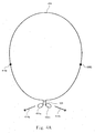
- FIG. 1A illustrates a schematic diagram of the earphone storage structure according to the first embodiment of the present invention.
- the earphone storage structure comprises a necklace 102 and earphones 106a and 106b connected together by a wire 104.
- Two rings 109a and 109b are formed in the two ends of the necklace 102 respectively.
- Two stoppers 108a and 108b are formed on the wire 104.
- the size of stoppers 108a and 108b are large than the size of the rings 109a and 109b.
- the wire 104 passes through the two rings 109a and 109b.
- the stopper 108a and the ring 109a together determine the extendable distance of the earphone 106a.
- the stopper 108b and the ring 109b together determine the extendable distance of the earphone 106b.
- a connector 110 of the wire 104 is formed in the location between the two stoppers 108a and 108b to connect with a hand-held device 112, such as a cell phone, a PDA or a walkman.
- the structure of the stopper 108a and 108b is similar to a bump.
- this hand-held device 112 When a hand-held device 112 is connected to the earphone storage structure, this hand-held device 112 may be hung on the neck of a user with the necklace 102. When the earphones 106a and 106b are not used, the hand-held device 112 can be hung on the neck as a pendant by the rings 109a and 109b catching the earphones 106a and 106b respectively. When using the earphones 106a and 106b, a user may pull out the earphones 106a and 106b following the direction indicated by the arrow 114a and 114b in Figure 1A. In an embodiment, switches are formed in the stoppers 108a and 108b respectively.
- switches are switched by the touching of the stoppers 108a and 108b and the rings 109a and 109b.
- a switch is only formed in one of the two stoppers 108a or 108b.
- switches are formed in the rings 109a and 109b respectively.
- a switch is only formed in one of the two rings 109a or 109b.
- a designed fastener 100 can be used to replace the ring.
- This fastener 100 includes a base 120 connected with the necklace 102.
- a ring 122 whose size is less than the size of earphone 106a is formed in the base 120.
- this earphone 106a may be stored in the base 120 to protect itself.
- a special location is set in the base 120 for storing the earphone 106a to make the face of the earphone 106a always toward the base 120 when the earphone 106a is stored in the special location.
- a switch 124 is formed in the base 120 to control the hand-held device 112.
- the switch 124 starts the hand-held device 112 once the earphone leaves the base 120.
- the earphone 106a or/and earphone 106b touches the switch 124 to stop the hand-held device 112.
- an additional microphone (not shown in this figure) can be installed on the wire 104. A user can use this microphone to answer a call.
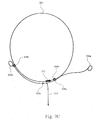
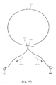
- FIG. 2A illustrates a schematic diagram of the earphone storage structure according to the second embodiment of the present invention.
- the earphone storage structure comprises an earphone's wire 204 and two earphones 206a and 206b connected together by this wire 204.
- Two rings 209a and 209b are formed in the two ends of the wire 204 respectively.
- the size of the rings 209a and 209b is less than the size of the earphones 206a and 206b.
- a stopper 208a whose size is larger than the size of the ring 209b is formed in the location between the earphone 206b and the ring 209a in the wire 204.
- the stopper 208a is used to limit the extendable distance of the earphones 206b.
- a stopper 208b whose size is larger than the size of the ring 209a is formed in the location between the earphone 206a and the ring 209b in the wire 204.
- the stopper 208b is used to limit the extendable distance of the earphones 206a.
- the structure of the stopper 208a and 208b is similar to a bump.
- the earphone 206a, the stopper 208b and the ring 209b are sequentially formed in one end of the wire 204.
- the earphone 206b, the stopper 208a and the ring 209a are sequentially formed in another end of the wire 204.
- the earphone 206b passes through the ring 209b.
- the earphone 206a passes through the ring 209a.
- the connector 210 is formed in the location between the stopper 208a and the ring 209a.
- the microphone 212 is formed in the location between the stopper 208b and the ring 209b. In another embodiment, the connector 210 and the microphone 212 may also be formed in other locations.
- a user may hang the wire 204 on his/her neck to use the earphones.
- the rings 209a and 209b may catch the earphones 206a and 206b respectively.
- a part of the wire 204 may overlap together in such a structure to reduce the length of the wire 204 and prevent the wire 204 from getting tangled.
- a user may pull out the earphones 206a and 206b in the direction indicated by the arrows 214a and 214b in the figure 2B.
- the stopper 208b and the ring 209a together determine the extendable distance of the earphone 206a.
- the stopper 208a and the ring 209b together determine the extendable distance of the earphone 206b.
- a user may only pull out one of the earphones 206a and 206b.
- switches are formed in the stoppers 208a and 208b respectively. These switches are switched by touching of the stoppers 208a and 208b and the rings 209a and 209b.
- a switch is only formed in one of the two stoppers 208a and 208b.
- switches are formed in the rings 209a and 209b respectively.
- switch is only formed in one of the two rings 209a and 209b.
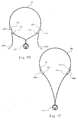
- FIG. 3A illustrates a schematic diagram of the earphone storage structure according to the third embodiment of the present invention.
- the earphone storage structure comprises an earphone's wire 304 and earphones 306a and 306b connected together by this wire 304.
- a ring 309 is formed in the wire 304.
- the size of ring 309 is less than the size of the earphones 306a and 306b.
- the earphones 306a and 306b are located in the two sides of the ring 309 respectively. Therefore, there is an overlap of the wire 304 in the ring 309.
- a stopper 308a whose size is larger than the size of the ring 309 is formed in the location away from the earphone 306a in the wire 304.
- the stopper 308a is used to limit the extendable distance of the earphones 306a.
- a stopper 308b whose size is larger than the size of the ring 309 is formed in the location away from the earphone 306b in the wire 304.
- the stopper 308b is used to limit the extendable distance of the earphones 306b.
- the structure of the stopper 308a and 308b is similar to a bump
- a user may hang the wire 304 on the neck to use the earphones.
- the ring 309 may catch the earphones 306a and 306b respectively to prevent the wire 304 from getting tangled.
- a user may pull out the earphones 306a and 306b in the direction indicated by the arrows 314a and 314bin the figure 3B.
- the stopper 308a and the ring 309 together determine the extendable distance of the earphone 306a.
- the stopper 308 and the ring 309 together determine the extendable distance of the earphone 306b.
- switches are formed in the stoppers 308a and 308b respectively. These switches are switched by the touching of the stoppers 308a and 308b and the ring 309. In another embodiment, the switch is only formed in one of the two stoppers 308a or 308b. Moreover, in another embodiment, the switch is formed in the ring 309.
- FIG. 4A illustrates a schematic diagram of the earphone storage structure according to the fourth embodiment of the present invention.
- the earphone storage structure comprises an earphone's wire 404 and earphones 406a and 406b connected together by this wire 404.
- a ring 409 is formed in the wire 404.
- the size of ring 409 is less than the size of the earphones 406a and 406b.
- the main difference between the third embodiment and the fourth embodiment is that the earphones 406a and 406b are located on the same side of the ring 409.
- a stopper 408a whose size is larger than the size of the ring 409 is formed in a location away from the earphone 406a in the wire 404.
- the stopper 408a is used to limit the extendable distance of the earphones 406a.
- a stopper 408b whose size is larger than the size of the ring 409 is formed in a location away from the earphone 406b in the wire 404.
- the stopper 408b is used to limit the extendable distance of the earphones 406b.
- the structure of the stopper 408a and 408b is similar to a bump
- a user may hang the wire 404 on his/her neck to use the earphones.
- the ring 409 may catch the earphones 406a and 406b respectively to avoid the wire 404 from getting tangled.
- a user may pull out the earphones 406a and 406b in the direction indicated by the arrows 414a and 414b in the figure 4B.
- the fastener structure 100 described in the first embodiment may also be used in the fourth embodiment.
- switches are formed in the stoppers 408a and 408b respectively. These switches are switched by the touching of the stoppers 408a and 408b and the ring 409.
- the switch is only formed in one of the two stoppers 408a and 408b.
- switch is formed in the ring 409.
- two rings and two stoppers used in the foregoing embodiments limit the extendable distances of the earphones.
- one ring and one stopper design may also be used in the store structure.
- the earphone storage structure comprises a stopper and a fastener.
- the earphone and the stopper are located on different sides of the fastener.
- the fastener and the stopper may together determine the extendable distance of the earphone to avoid the earphone's wire wound together.
Landscapes
- Physics & Mathematics (AREA)
- Engineering & Computer Science (AREA)
- Acoustics & Sound (AREA)
- Signal Processing (AREA)
- Headphones And Earphones (AREA)
Abstract
Description
- The present invention is about a storage structure, and more particularly, is about a structure for storing earphone.
- Listening to the music is a common leisure time activity. Earphones are used to listen to music to avoid disturbing others. However, when earphones are not being used, it is difficult to store them. Because of the long earphone wire, the wire is always wound together when the earphone is directly placed into a bag for storage.
- Typically, a storage box with a winding reel is used to store earphones. The winding reel is used to wind the earphone's wire into the store box to prevent the earphone wire from getting tangled up. However, if such a storage method is used, a user must take an additional storage box to store the earphones in. It is still not very convenient for users because the earphones must initially be removed from the box before they can be used. This is especially inconvenient, when the earphones are urgently needed.
- Therefore, an earphone storage structure that can avoid the foregoing problems is required.
- Therefore, the main purpose of the present invention is to provide an earphone storage structure that may prevent the earphone's wire from getting tangled up.
- Accordingly, the present invention provides an earphone storage structure comprising a necklace, two fasteners formed in the two ends of the necklace respectively and a stopper formed in the necklace. The size of the fasteners is less than the size of the stopper and the size of the earphones. Therefore, fasteners may couple the earphone with the necklace. Moreover, the stopper and the fasteners may together determine the extendable distance of the earphones.
- According to an embodiment, the earphone storage structure further comprises a switch formed in the stopper. The switch is switched when the fastener fastens with the stopper.
- According to an embodiment, the earphone storage structure further comprises a switch formed in the fastener.
- In another embodiment, the present invention provides an earphone storage structure comprising a fastener and a stopper formed in the earphone's wire. The size of the fastener is less than the size of the stopper and the size of the earphone. The stopper and the fastener may together determine the extendable distance of the earphone. In an embodiment, the two earphones are extended from the fastener in the same direction and are located on the same side of the fastener. In another embodiment, the two earphones are extended from the fastener in the opposite direction and are located on different sides of the fastener.
- According to an embodiment, the earphone storage structure further comprises a switch formed in the stopper. The switch is switched when the fastener fastens with the stopper.
- According to an embodiment, the earphone storage structure further comprises a switch formed in the fastener.
- The foregoing aspects and many of the attendant advantages of this invention will become more readily appreciated and better understood by referencing the following detailed description, when taken in conjunction with the accompanying drawings, wherein:
- Figure 1A to Figure 1E illustrate schematic diagrams of the earphone storage structure according to the first embodiment of the present invention;
- Figure 2A to Figure 2C illustrate schematic diagrams of the earphone storage structure according to the second embodiment of the present invention;
- Figure 3A to Figure 3B illustrate schematic diagrams of the earphone storage structure according to the third embodiment of the present invention; and
- Figure 4A to Figure 4B illustrate schematic diagrams of the earphone storage structure according to the fourth embodiment of the present invention.
- 1. Figure 1A illustrates a schematic diagram of the earphone storage structure according to the first embodiment of the present invention. The earphone storage structure comprises a
necklace 102 andearphones wire 104. Tworings necklace 102 respectively. Twostoppers wire 104. The size ofstoppers rings wire 104 passes through the tworings stopper 108a and thering 109a together determine the extendable distance of theearphone 106a. Thestopper 108b and thering 109b together determine the extendable distance of theearphone 106b. Aconnector 110 of thewire 104 is formed in the location between the twostoppers device 112, such as a cell phone, a PDA or a walkman. In an embodiment, the structure of thestopper - When a hand-held
device 112 is connected to the earphone storage structure, this hand-helddevice 112 may be hung on the neck of a user with thenecklace 102. When theearphones device 112 can be hung on the neck as a pendant by therings earphones earphones earphones arrow stoppers stoppers rings stoppers rings rings - It is noticed that, in these embodiments, the connection of the
necklace 102 and thewire 104 passes through the catchingrings earphones fastener 100 can be used to replace the ring. Thisfastener 100 includes abase 120 connected with thenecklace 102. Aring 122 whose size is less than the size ofearphone 106a is formed in thebase 120. When theearphone 106a is not used, thisearphone 106a may be stored in thebase 120 to protect itself. In an embodiment, a special location is set in thebase 120 for storing theearphone 106a to make the face of theearphone 106a always toward thebase 120 when theearphone 106a is stored in the special location. - In another embodiment, as shown in the figure 1 D, a
switch 124 is formed in thebase 120 to control the hand-helddevice 112. When theearphone 106a or/andearphone 106b are used, theswitch 124 starts the hand-helddevice 112 once the earphone leaves thebase 120. On the other hand, as shown in the figure 1 E, when the earphones are located in thebase 120, theearphone 106a or/andearphone 106b touches theswitch 124 to stop the hand-helddevice 112. In another embodiment, if the hand-helddevice 112 is a cell phone, an additional microphone (not shown in this figure) can be installed on thewire 104. A user can use this microphone to answer a call. - Figure 2A illustrates a schematic diagram of the earphone storage structure according to the second embodiment of the present invention. The earphone storage structure comprises an earphone's
wire 204 and twoearphones wire 204. Tworings wire 204 respectively. The size of therings earphones stopper 208a whose size is larger than the size of thering 209b is formed in the location between theearphone 206b and thering 209a in thewire 204. Thestopper 208a is used to limit the extendable distance of theearphones 206b. Astopper 208b whose size is larger than the size of thering 209a is formed in the location between theearphone 206a and thering 209b in thewire 204. Thestopper 208b is used to limit the extendable distance of theearphones 206a. In an embodiment, the structure of thestopper - In other words, according to this embodiment, the
earphone 206a, thestopper 208b and thering 209b are sequentially formed in one end of thewire 204. Theearphone 206b, thestopper 208a and thering 209a are sequentially formed in another end of thewire 204. Theearphone 206b passes through thering 209b. Theearphone 206a passes through thering 209a. According to this embodiment, theconnector 210 is formed in the location between thestopper 208a and thering 209a. Themicrophone 212 is formed in the location between thestopper 208b and thering 209b. In another embodiment, theconnector 210 and themicrophone 212 may also be formed in other locations. - A user may hang the
wire 204 on his/her neck to use the earphones. Moreover, as shown in the figure 2A, therings earphones wire 204 may overlap together in such a structure to reduce the length of thewire 204 and prevent thewire 204 from getting tangled. When using theearphones earphones arrows stopper 208b and thering 209a together determine the extendable distance of theearphone 206a. Thestopper 208a and thering 209b together determine the extendable distance of theearphone 206b. On the other hand, as shown in the figure 2C, a user may only pull out one of theearphones - It is noticed that the
fastener structure 100 described in the first embodiment may also be used in the second embodiment. In an embodiment, switches are formed in thestoppers stoppers rings stoppers rings rings - Figure 3A illustrates a schematic diagram of the earphone storage structure according to the third embodiment of the present invention. The earphone storage structure comprises an earphone's
wire 304 andearphones wire 304. Aring 309 is formed in thewire 304. The size ofring 309 is less than the size of theearphones earphones ring 309 respectively. Therefore, there is an overlap of thewire 304 in thering 309. Astopper 308a whose size is larger than the size of thering 309 is formed in the location away from theearphone 306a in thewire 304. Thestopper 308a is used to limit the extendable distance of theearphones 306a. On the other hand, astopper 308b whose size is larger than the size of thering 309 is formed in the location away from theearphone 306b in thewire 304. Thestopper 308b is used to limit the extendable distance of theearphones 306b. In an embodiment, the structure of thestopper - A user may hang the
wire 304 on the neck to use the earphones. Moreover, as shown in the figure 3A, thering 309 may catch theearphones wire 304 from getting tangled. When using theearphones earphones arrows 314a and 314bin the figure 3B. Thestopper 308a and thering 309 together determine the extendable distance of theearphone 306a. The stopper 308 and thering 309 together determine the extendable distance of theearphone 306b. - It is seen that the
fastener 100 structure described in the first embodiment may also be used in the third embodiment. In an embodiment, switches are formed in thestoppers stoppers ring 309. In another embodiment, the switch is only formed in one of the twostoppers ring 309. - Figure 4A illustrates a schematic diagram of the earphone storage structure according to the fourth embodiment of the present invention. The earphone storage structure comprises an earphone's
wire 404 andearphones wire 404. Aring 409 is formed in thewire 404. The size ofring 409 is less than the size of theearphones earphones ring 409. Astopper 408a whose size is larger than the size of thering 409 is formed in a location away from theearphone 406a in thewire 404. Thestopper 408a is used to limit the extendable distance of theearphones 406a. On the other hand, astopper 408b whose size is larger than the size of thering 409 is formed in a location away from theearphone 406b in thewire 404. Thestopper 408b is used to limit the extendable distance of theearphones 406b. In an embodiment, the structure of thestopper - A user may hang the
wire 404 on his/her neck to use the earphones. Moreover, as shown in the figure 4A, thering 409 may catch theearphones wire 404 from getting tangled. When using theearphones earphones arrows fastener structure 100 described in the first embodiment may also be used in the fourth embodiment. In an embodiment, switches are formed in thestoppers stoppers ring 409. In another embodiment, the switch is only formed in one of the twostoppers ring 409. - It is noticed that two rings and two stoppers used in the foregoing embodiments limit the extendable distances of the earphones. However, in another embodiment, based on actual user habits, one ring and one stopper design may also be used in the store structure.
- Accordingly, the earphone storage structure comprises a stopper and a fastener. The earphone and the stopper are located on different sides of the fastener. The fastener and the stopper may together determine the extendable distance of the earphone to avoid the earphone's wire wound together.
- As is understood by a person skilled in the art, the foregoing descriptions of the preferred embodiments of the present invention are an illustration of the present invention rather than a limitation thereof. Various modifications and similar arrangements are included within the spirit and scope of the appended claims. The scope of the claims should be accorded to the broadest interpretation so as to encompass all such modifications and similar structures. While preferred embodiments of the invention have been illustrated and described, it will be appreciated that various changes can be made therein without departing from the spirit and scope of the invention.
Claims (16)
- An earphone storage structure, comprising:a necklace;two bases formed in the two ends of said necklace, wherein each of said bases includes a fastener; andat least one earphone connected with a wire and at least one stopper formed in said wire, wherein when an earphone is not used, said fastener may fasten said earphone and fix said earphone on said base and when said earphone is used, said fastener may fasten a corresponding stopper to limit a distance of said earphone away from said base.
- The structure of claim 1, further comprising a connector formed in said wire to connect with a hand-held device.
- The structure of claim 2, further comprising at least one switch located in said base to control said hand-held device.
- The structure of claim 2, wherein said hand-held device is a cell phone, a media player or a PDA.
- The structure of claim 1, further comprising a microphone formed in said wire.
- The structure of claim 1, wherein said fastener is a ring and the size of said ring is less than the size of said earphone and the size of said stopper.
- The structure of claim 1, further comprising at least one switch located in said base or in said stopper.
- An earphone storage structure, comprising:at least one earphone connected with a wire;at least one fastener, wherein said earphone passes through said fastener and fastened with said fastener; andat least one stopper formed in said wire, wherein said stopper and said fastener together limit a distance of said earphone away from said fastener.
- The structure of claim 8, further comprising a connector formed in said wire to connect with a hand-held device.
- The structure of claim 9, further comprising at least one switch located in said fastener to control said hand-held device.
- The structure of claim 9, wherein said hand-held device is a cell phone, a media player or a PDA.
- The structure of claim 8, further comprising a microphone formed in said wire.
- The structure of claim 8, wherein said fastener is a ring and the size of said ring is less than the size of said earphone and the size of said stopper.
- The structure of claim 8, wherein said earphones are located in different sides of said fastener.
- The structure of claim 8, wherein said earphones are located in one side of said fastener.
- The structure of claim 8, further comprising at least one switch located in said base or in said stopper.
Applications Claiming Priority (1)
| Application Number | Priority Date | Filing Date | Title |
|---|---|---|---|
| CN2006100595953A CN101035392B (en) | 2006-03-09 | 2006-03-09 | Headphone storage structure |
Publications (3)
| Publication Number | Publication Date |
|---|---|
| EP1833275A2 true EP1833275A2 (en) | 2007-09-12 |
| EP1833275A3 EP1833275A3 (en) | 2009-04-08 |
| EP1833275B1 EP1833275B1 (en) | 2010-11-17 |
Family
ID=38124102
Family Applications (1)
| Application Number | Title | Priority Date | Filing Date |
|---|---|---|---|
| EP06120957A Not-in-force EP1833275B1 (en) | 2006-03-09 | 2006-09-20 | An earphone storage structure |
Country Status (4)
| Country | Link |
|---|---|
| EP (1) | EP1833275B1 (en) |
| CN (1) | CN101035392B (en) |
| AT (1) | ATE488967T1 (en) |
| DE (1) | DE602006018253D1 (en) |
Cited By (4)
| Publication number | Priority date | Publication date | Assignee | Title |
|---|---|---|---|---|
| USD626948S1 (en) | 2010-02-24 | 2010-11-09 | Koss Corporation | Earphone |
| US8249286B2 (en) | 2009-08-24 | 2012-08-21 | Koss Corporation | Interconnecting earphones |
| CN106028192A (en) * | 2016-06-30 | 2016-10-12 | 青岛歌尔声学科技有限公司 | Bluetooth sports headset |
| FR3049147A1 (en) * | 2016-03-16 | 2017-09-22 | Sophian Abdessadok | MULTIFUNCTIONAL SUPPORT FOR WIRED AUDIO HEADPHONES |
Families Citing this family (2)
| Publication number | Priority date | Publication date | Assignee | Title |
|---|---|---|---|---|
| CN103974155A (en) * | 2013-01-27 | 2014-08-06 | 厦门锐思达机电科技有限公司 | Necklace type Bluetooth headset |
| KR101687623B1 (en) * | 2015-06-15 | 2016-12-19 | 엘지전자 주식회사 | Wireless sound equipment |
Family Cites Families (13)
| Publication number | Priority date | Publication date | Assignee | Title |
|---|---|---|---|---|
| CN2251912Y (en) * | 1996-03-11 | 1997-04-16 | 施舒 | Necklace with earphone |
| US6091832A (en) * | 1996-08-12 | 2000-07-18 | Interval Research Corporation | Wearable personal audio loop apparatus |
| JPH10155192A (en) * | 1996-11-22 | 1998-06-09 | Kenji Wada | Neck hanging stereo earphone |
| CN2372858Y (en) * | 1999-01-19 | 2000-04-05 | 曾勇 | Earphone with talking switch |
| JP4296672B2 (en) * | 2000-02-16 | 2009-07-15 | ソニー株式会社 | Headphone locking device and headphones equipped with the same |
| JP3596601B2 (en) * | 2000-06-29 | 2004-12-02 | 日本電気株式会社 | Portable audio equipment |
| GB2369742A (en) * | 2000-11-30 | 2002-06-05 | Nokia Mobile Phones Ltd | Neck strap accessory for audio device having wired earpiece |
| JP2002171326A (en) * | 2000-12-01 | 2002-06-14 | Tomoyuki Samoto | Portable telephone set |
| EP1333649A1 (en) * | 2002-01-30 | 2003-08-06 | Sony International (Europe) GmbH | Mobile communication device with a retractable headset kit and automatic call control |
| FI5924U1 (en) * | 2002-05-31 | 2003-09-05 | Nokia Corp | Carrier and combination of this and electronic communication device |
| DE202004016147U1 (en) * | 2004-10-19 | 2005-01-13 | Beutnagel, Jeanette | Decorative earphones, have cable which forms loop around users neck when earpiece end of cable is attached to piece of jewelry |
| DE202005016624U1 (en) * | 2005-10-24 | 2006-03-09 | Kuo, Chin-Chang, Shu Lin | Neck hangable earphone for portable electronic music player, has hanging cord into which earphone cable is embedded, where cable hangs in end areas outside cord, and includes two clamps which allows change of position of cable |
| TWI288575B (en) * | 2006-01-11 | 2007-10-11 | High Tech Comp Corp | Earphone collecting structure |
-
2006
- 2006-03-09 CN CN2006100595953A patent/CN101035392B/en not_active Expired - Fee Related
- 2006-09-20 AT AT06120957T patent/ATE488967T1/en not_active IP Right Cessation
- 2006-09-20 EP EP06120957A patent/EP1833275B1/en not_active Not-in-force
- 2006-09-20 DE DE602006018253T patent/DE602006018253D1/en active Active
Non-Patent Citations (1)
| Title |
|---|
| None |
Cited By (5)
| Publication number | Priority date | Publication date | Assignee | Title |
|---|---|---|---|---|
| US8249286B2 (en) | 2009-08-24 | 2012-08-21 | Koss Corporation | Interconnecting earphones |
| USD626948S1 (en) | 2010-02-24 | 2010-11-09 | Koss Corporation | Earphone |
| FR3049147A1 (en) * | 2016-03-16 | 2017-09-22 | Sophian Abdessadok | MULTIFUNCTIONAL SUPPORT FOR WIRED AUDIO HEADPHONES |
| CN106028192A (en) * | 2016-06-30 | 2016-10-12 | 青岛歌尔声学科技有限公司 | Bluetooth sports headset |
| CN106028192B (en) * | 2016-06-30 | 2022-05-17 | 青岛歌尔声学科技有限公司 | Bluetooth motion earphone |
Also Published As
| Publication number | Publication date |
|---|---|
| EP1833275A3 (en) | 2009-04-08 |
| ATE488967T1 (en) | 2010-12-15 |
| EP1833275B1 (en) | 2010-11-17 |
| CN101035392B (en) | 2012-06-27 |
| DE602006018253D1 (en) | 2010-12-30 |
| CN101035392A (en) | 2007-09-12 |
Similar Documents
| Publication | Publication Date | Title |
|---|---|---|
| US9973844B1 (en) | Headphone stand | |
| US7077693B1 (en) | Cable management device | |
| US7399199B2 (en) | Cable management device | |
| US9340341B2 (en) | Cord management organizer | |
| JP6091438B2 (en) | Extension socket for portable media player | |
| US9648407B2 (en) | System and method for managing headphone wires | |
| US7936895B2 (en) | Earphone storage structure | |
| US20160066076A1 (en) | Ear-Bud Storage | |
| US20140198927A1 (en) | Wireless earphone | |
| US8848965B2 (en) | Earbud cord anti-tangling device | |
| US20150163580A1 (en) | Systems for earphone cable management | |
| EP1833275B1 (en) | An earphone storage structure | |
| JP2011139435A (en) | Stereo headphone, slider for stereo headphone, and method of folding stereo headphone | |
| US20050148313A1 (en) | Headset cord retainer | |
| US20140060879A1 (en) | Systems and methods for storing a cable | |
| JP5597858B2 (en) | Headphone cable entanglement prevention structure | |
| CN211089927U (en) | Novel earphone cord is accomodate device | |
| US9247035B1 (en) | Twisted case | |
| CN203761562U (en) | Self cord winding type earphone | |
| CN1244092A (en) | Headphone Storage Reel Box | |
| KR20050029659A (en) | Earphone head device | |
| CN2285039Y (en) | Storage unit for earphone and microphone cables for hands-free handsets | |
| JP2015032838A (en) | Cord holder | |
| CN215734399U (en) | Can accomodate cell-phone shell of earphone | |
| US20220159364A1 (en) | Earphone Cord Containment Adaptor and Holder |
Legal Events
| Date | Code | Title | Description |
|---|---|---|---|
| PUAI | Public reference made under article 153(3) epc to a published international application that has entered the european phase |
Free format text: ORIGINAL CODE: 0009012 |
|
| AK | Designated contracting states |
Kind code of ref document: A2 Designated state(s): AT BE BG CH CY CZ DE DK EE ES FI FR GB GR HU IE IS IT LI LT LU LV MC NL PL PT RO SE SI SK TR |
|
| AX | Request for extension of the european patent |
Extension state: AL BA HR MK YU |
|
| 17P | Request for examination filed |
Effective date: 20081114 |
|
| PUAL | Search report despatched |
Free format text: ORIGINAL CODE: 0009013 |
|
| AK | Designated contracting states |
Kind code of ref document: A3 Designated state(s): AT BE BG CH CY CZ DE DK EE ES FI FR GB GR HU IE IS IT LI LT LU LV MC NL PL PT RO SE SI SK TR |
|
| AX | Request for extension of the european patent |
Extension state: AL BA HR MK RS |
|
| 17Q | First examination report despatched |
Effective date: 20091020 |
|
| AKX | Designation fees paid |
Designated state(s): AT BE BG CH CY CZ DE DK EE ES FI FR GB GR HU IE IS IT LI LT LU LV MC NL PL PT RO SE SI SK TR |
|
| GRAP | Despatch of communication of intention to grant a patent |
Free format text: ORIGINAL CODE: EPIDOSNIGR1 |
|
| RAP1 | Party data changed (applicant data changed or rights of an application transferred) |
Owner name: HTC CORPORATION |
|
| GRAS | Grant fee paid |
Free format text: ORIGINAL CODE: EPIDOSNIGR3 |
|
| GRAA | (expected) grant |
Free format text: ORIGINAL CODE: 0009210 |
|
| AK | Designated contracting states |
Kind code of ref document: B1 Designated state(s): AT BE BG CH CY CZ DE DK EE ES FI FR GB GR HU IE IS IT LI LT LU LV MC NL PL PT RO SE SI SK TR |
|
| REG | Reference to a national code |
Ref country code: GB Ref legal event code: FG4D |
|
| REG | Reference to a national code |
Ref country code: CH Ref legal event code: EP |
|
| REG | Reference to a national code |
Ref country code: IE Ref legal event code: FG4D |
|
| REF | Corresponds to: |
Ref document number: 602006018253 Country of ref document: DE Date of ref document: 20101230 Kind code of ref document: P |
|
| REG | Reference to a national code |
Ref country code: NL Ref legal event code: T3 |
|
| LTIE | Lt: invalidation of european patent or patent extension |
Effective date: 20101117 |
|
| PG25 | Lapsed in a contracting state [announced via postgrant information from national office to epo] |
Ref country code: LT Free format text: LAPSE BECAUSE OF FAILURE TO SUBMIT A TRANSLATION OF THE DESCRIPTION OR TO PAY THE FEE WITHIN THE PRESCRIBED TIME-LIMIT Effective date: 20101117 |
|
| PG25 | Lapsed in a contracting state [announced via postgrant information from national office to epo] |
Ref country code: SE Free format text: LAPSE BECAUSE OF FAILURE TO SUBMIT A TRANSLATION OF THE DESCRIPTION OR TO PAY THE FEE WITHIN THE PRESCRIBED TIME-LIMIT Effective date: 20101117 Ref country code: PT Free format text: LAPSE BECAUSE OF FAILURE TO SUBMIT A TRANSLATION OF THE DESCRIPTION OR TO PAY THE FEE WITHIN THE PRESCRIBED TIME-LIMIT Effective date: 20110317 Ref country code: CY Free format text: LAPSE BECAUSE OF FAILURE TO SUBMIT A TRANSLATION OF THE DESCRIPTION OR TO PAY THE FEE WITHIN THE PRESCRIBED TIME-LIMIT Effective date: 20101117 Ref country code: LV Free format text: LAPSE BECAUSE OF FAILURE TO SUBMIT A TRANSLATION OF THE DESCRIPTION OR TO PAY THE FEE WITHIN THE PRESCRIBED TIME-LIMIT Effective date: 20101117 Ref country code: IS Free format text: LAPSE BECAUSE OF FAILURE TO SUBMIT A TRANSLATION OF THE DESCRIPTION OR TO PAY THE FEE WITHIN THE PRESCRIBED TIME-LIMIT Effective date: 20110317 Ref country code: BG Free format text: LAPSE BECAUSE OF FAILURE TO SUBMIT A TRANSLATION OF THE DESCRIPTION OR TO PAY THE FEE WITHIN THE PRESCRIBED TIME-LIMIT Effective date: 20110217 Ref country code: AT Free format text: LAPSE BECAUSE OF FAILURE TO SUBMIT A TRANSLATION OF THE DESCRIPTION OR TO PAY THE FEE WITHIN THE PRESCRIBED TIME-LIMIT Effective date: 20101117 Ref country code: FI Free format text: LAPSE BECAUSE OF FAILURE TO SUBMIT A TRANSLATION OF THE DESCRIPTION OR TO PAY THE FEE WITHIN THE PRESCRIBED TIME-LIMIT Effective date: 20101117 Ref country code: SI Free format text: LAPSE BECAUSE OF FAILURE TO SUBMIT A TRANSLATION OF THE DESCRIPTION OR TO PAY THE FEE WITHIN THE PRESCRIBED TIME-LIMIT Effective date: 20101117 |
|
| PG25 | Lapsed in a contracting state [announced via postgrant information from national office to epo] |
Ref country code: GR Free format text: LAPSE BECAUSE OF FAILURE TO SUBMIT A TRANSLATION OF THE DESCRIPTION OR TO PAY THE FEE WITHIN THE PRESCRIBED TIME-LIMIT Effective date: 20110218 |
|
| PG25 | Lapsed in a contracting state [announced via postgrant information from national office to epo] |
Ref country code: BE Free format text: LAPSE BECAUSE OF FAILURE TO SUBMIT A TRANSLATION OF THE DESCRIPTION OR TO PAY THE FEE WITHIN THE PRESCRIBED TIME-LIMIT Effective date: 20101117 Ref country code: CZ Free format text: LAPSE BECAUSE OF FAILURE TO SUBMIT A TRANSLATION OF THE DESCRIPTION OR TO PAY THE FEE WITHIN THE PRESCRIBED TIME-LIMIT Effective date: 20101117 Ref country code: ES Free format text: LAPSE BECAUSE OF FAILURE TO SUBMIT A TRANSLATION OF THE DESCRIPTION OR TO PAY THE FEE WITHIN THE PRESCRIBED TIME-LIMIT Effective date: 20110228 Ref country code: EE Free format text: LAPSE BECAUSE OF FAILURE TO SUBMIT A TRANSLATION OF THE DESCRIPTION OR TO PAY THE FEE WITHIN THE PRESCRIBED TIME-LIMIT Effective date: 20101117 |
|
| PG25 | Lapsed in a contracting state [announced via postgrant information from national office to epo] |
Ref country code: SK Free format text: LAPSE BECAUSE OF FAILURE TO SUBMIT A TRANSLATION OF THE DESCRIPTION OR TO PAY THE FEE WITHIN THE PRESCRIBED TIME-LIMIT Effective date: 20101117 Ref country code: RO Free format text: LAPSE BECAUSE OF FAILURE TO SUBMIT A TRANSLATION OF THE DESCRIPTION OR TO PAY THE FEE WITHIN THE PRESCRIBED TIME-LIMIT Effective date: 20101117 Ref country code: PL Free format text: LAPSE BECAUSE OF FAILURE TO SUBMIT A TRANSLATION OF THE DESCRIPTION OR TO PAY THE FEE WITHIN THE PRESCRIBED TIME-LIMIT Effective date: 20101117 Ref country code: DK Free format text: LAPSE BECAUSE OF FAILURE TO SUBMIT A TRANSLATION OF THE DESCRIPTION OR TO PAY THE FEE WITHIN THE PRESCRIBED TIME-LIMIT Effective date: 20101117 |
|
| PLBE | No opposition filed within time limit |
Free format text: ORIGINAL CODE: 0009261 |
|
| STAA | Information on the status of an ep patent application or granted ep patent |
Free format text: STATUS: NO OPPOSITION FILED WITHIN TIME LIMIT |
|
| 26N | No opposition filed |
Effective date: 20110818 |
|
| REG | Reference to a national code |
Ref country code: DE Ref legal event code: R097 Ref document number: 602006018253 Country of ref document: DE Effective date: 20110818 |
|
| PG25 | Lapsed in a contracting state [announced via postgrant information from national office to epo] |
Ref country code: IT Free format text: LAPSE BECAUSE OF FAILURE TO SUBMIT A TRANSLATION OF THE DESCRIPTION OR TO PAY THE FEE WITHIN THE PRESCRIBED TIME-LIMIT Effective date: 20101117 |
|
| PG25 | Lapsed in a contracting state [announced via postgrant information from national office to epo] |
Ref country code: MC Free format text: LAPSE BECAUSE OF NON-PAYMENT OF DUE FEES Effective date: 20110930 |
|
| REG | Reference to a national code |
Ref country code: CH Ref legal event code: PL |
|
| REG | Reference to a national code |
Ref country code: IE Ref legal event code: MM4A |
|
| PG25 | Lapsed in a contracting state [announced via postgrant information from national office to epo] |
Ref country code: IE Free format text: LAPSE BECAUSE OF NON-PAYMENT OF DUE FEES Effective date: 20110920 Ref country code: LI Free format text: LAPSE BECAUSE OF NON-PAYMENT OF DUE FEES Effective date: 20110930 Ref country code: CH Free format text: LAPSE BECAUSE OF NON-PAYMENT OF DUE FEES Effective date: 20110930 |
|
| PG25 | Lapsed in a contracting state [announced via postgrant information from national office to epo] |
Ref country code: LU Free format text: LAPSE BECAUSE OF NON-PAYMENT OF DUE FEES Effective date: 20110920 |
|
| PG25 | Lapsed in a contracting state [announced via postgrant information from national office to epo] |
Ref country code: TR Free format text: LAPSE BECAUSE OF FAILURE TO SUBMIT A TRANSLATION OF THE DESCRIPTION OR TO PAY THE FEE WITHIN THE PRESCRIBED TIME-LIMIT Effective date: 20101117 |
|
| PG25 | Lapsed in a contracting state [announced via postgrant information from national office to epo] |
Ref country code: HU Free format text: LAPSE BECAUSE OF FAILURE TO SUBMIT A TRANSLATION OF THE DESCRIPTION OR TO PAY THE FEE WITHIN THE PRESCRIBED TIME-LIMIT Effective date: 20101117 |
|
| REG | Reference to a national code |
Ref country code: FR Ref legal event code: PLFP Year of fee payment: 11 |
|
| REG | Reference to a national code |
Ref country code: FR Ref legal event code: PLFP Year of fee payment: 12 |
|
| REG | Reference to a national code |
Ref country code: FR Ref legal event code: PLFP Year of fee payment: 13 |
|
| PGFP | Annual fee paid to national office [announced via postgrant information from national office to epo] |
Ref country code: DE Payment date: 20180904 Year of fee payment: 13 |
|
| PGFP | Annual fee paid to national office [announced via postgrant information from national office to epo] |
Ref country code: GB Payment date: 20180919 Year of fee payment: 13 Ref country code: NL Payment date: 20180912 Year of fee payment: 13 |
|
| PGFP | Annual fee paid to national office [announced via postgrant information from national office to epo] |
Ref country code: FR Payment date: 20190815 Year of fee payment: 14 |
|
| REG | Reference to a national code |
Ref country code: DE Ref legal event code: R119 Ref document number: 602006018253 Country of ref document: DE |
|
| REG | Reference to a national code |
Ref country code: NL Ref legal event code: MM Effective date: 20191001 |
|
| PG25 | Lapsed in a contracting state [announced via postgrant information from national office to epo] |
Ref country code: NL Free format text: LAPSE BECAUSE OF NON-PAYMENT OF DUE FEES Effective date: 20191001 Ref country code: DE Free format text: LAPSE BECAUSE OF NON-PAYMENT OF DUE FEES Effective date: 20200401 |
|
| GBPC | Gb: european patent ceased through non-payment of renewal fee |
Effective date: 20190920 |
|
| PG25 | Lapsed in a contracting state [announced via postgrant information from national office to epo] |
Ref country code: GB Free format text: LAPSE BECAUSE OF NON-PAYMENT OF DUE FEES Effective date: 20190920 |
|
| PG25 | Lapsed in a contracting state [announced via postgrant information from national office to epo] |
Ref country code: FR Free format text: LAPSE BECAUSE OF NON-PAYMENT OF DUE FEES Effective date: 20200930 |