EP1833264A1 - Image processing method - Google Patents
Image processing method Download PDFInfo
- Publication number
- EP1833264A1 EP1833264A1 EP05816611A EP05816611A EP1833264A1 EP 1833264 A1 EP1833264 A1 EP 1833264A1 EP 05816611 A EP05816611 A EP 05816611A EP 05816611 A EP05816611 A EP 05816611A EP 1833264 A1 EP1833264 A1 EP 1833264A1
- Authority
- EP
- European Patent Office
- Prior art keywords
- image data
- color
- noise
- image processing
- uniform
- Prior art date
- Legal status (The legal status is an assumption and is not a legal conclusion. Google has not performed a legal analysis and makes no representation as to the accuracy of the status listed.)
- Granted
Links
Images



Classifications
-
- H—ELECTRICITY
- H04—ELECTRIC COMMUNICATION TECHNIQUE
- H04N—PICTORIAL COMMUNICATION, e.g. TELEVISION
- H04N9/00—Details of colour television systems
- H04N9/64—Circuits for processing colour signals
- H04N9/646—Circuits for processing colour signals for image enhancement, e.g. vertical detail restoration, cross-colour elimination, contour correction, chrominance trapping filters
-
- H—ELECTRICITY
- H04—ELECTRIC COMMUNICATION TECHNIQUE
- H04N—PICTORIAL COMMUNICATION, e.g. TELEVISION
- H04N23/00—Cameras or camera modules comprising electronic image sensors; Control thereof
- H04N23/80—Camera processing pipelines; Components thereof
- H04N23/84—Camera processing pipelines; Components thereof for processing colour signals
- H04N23/843—Demosaicing, e.g. interpolating colour pixel values
-
- H—ELECTRICITY
- H04—ELECTRIC COMMUNICATION TECHNIQUE
- H04N—PICTORIAL COMMUNICATION, e.g. TELEVISION
- H04N9/00—Details of colour television systems
- H04N9/64—Circuits for processing colour signals
- H04N9/67—Circuits for processing colour signals for matrixing
-
- H—ELECTRICITY
- H04—ELECTRIC COMMUNICATION TECHNIQUE
- H04N—PICTORIAL COMMUNICATION, e.g. TELEVISION
- H04N25/00—Circuitry of solid-state image sensors [SSIS]; Control thereof
- H04N25/10—Circuitry of solid-state image sensors [SSIS]; Control thereof for transforming different wavelengths into image signals
- H04N25/11—Arrangement of colour filter arrays [CFA]; Filter mosaics
- H04N25/13—Arrangement of colour filter arrays [CFA]; Filter mosaics characterised by the spectral characteristics of the filter elements
- H04N25/134—Arrangement of colour filter arrays [CFA]; Filter mosaics characterised by the spectral characteristics of the filter elements based on three different wavelength filter elements
Definitions
- the present invention relates to an image processing method to be adopted to convert image data to a color space optimal for removal of noise from the image and color reproduction.
- non-patent reference 1 non-patent reference 1
- nonpatent reference 2 a bilateral filter
- noise is removed through Gaussian blur by using the ratios of pixel value differences relative to the standard deviation ⁇ as an argument in conjunction with spatial Gaussian blur
- the noise can be accurately removed in a manner optimal for the particular image structure, since the standard deviation value is not dependent upon the luminance. If the noise is to be removed without using such a uniform noise space, a process of generating a noise profile by determining the standard deviation in correspondence to each luminance level needs to be executed as disclosed in patent reference 2.
- a color space in which the luminance and chrominance are expressed by taking into consideration the human visual system is often used in image processing. Under normal circumstances, a uniform color space such as L*a*b* is routinely used, since such a uniform color space in which a color signal is expressed in a manner closer to human visual perception, is considered to assure superior color reproduction.
- an image processing method comprises: inputting color image data obtained by capturing an image at a given imaging sensitivity level; and converting the color image data to a specific uniform color space determined in correspondence to the imaging sensitivity level.
- gradation conversion characteristics based upon which the color image data are converted to the uniform color space are altered in correspondence to the imaging sensitivity level.
- the gradation conversion characteristics are nonlinear gradation conversion characteristics.
- an image processing method for converting image data having been input, which are expressed by a set of stimulus values having linear gradation characteristics relative to light intensity, to the color signals indicating a perceptive attribute by executing a specific type of nonlinear gradation conversion on the stimulus values assumed in the input image data comprises: executing the conversion from linear gradation to nonlinear gradation in a state in which an offset signal is applied to each of the stimulus values assumed in the image data.
- the image data are converted to color signals indicating a perceptive attribute that achieves a pseudo-uniform color space.
- the specific type of nonlinear gradation conversion is nonlinear gradation conversion having substantially square root characteristics.
- the offset signal assumes a value of 0 or a positive value.
- the image processing method according to any one of the 4th through 7th aspects it is preferred that when applying the offset signal to each of the stimulus values assumed in the image data, a value of the offset signal is adjusted in correspondence to the imaging sensitivity level with which the input image data have been captured.
- a specific width of the color signals resulting from the conversion is designated as a representative value representing noise characteristics of the input image data.
- the specific signal width is determined by capturing an image of a uniform surface, converting image data of the uniform plane to color signals indicating a perceptive attribute through the specific type of nonlinear gradation conversion and then ascertaining a standard deviation of the image data of the uniform plane having undergone the conversion.
- noise removal processing is executed by utilizing the representative value of the noise characteristics in a color space containing the color signals resulting from the conversion.
- the input image data are image data expressed with three stimulus values with X, Y and Z constituting reference color stimuli.
- the input image data are image data expressed with three stimulus values with R, G and B constituting reference color stimuli; the image data expressed with the three stimulus values with R, G and B constituting the reference color stimuli are converted to image data with three stimulus values X, Y and Z expressed through linear coupling of the reference color stimuli; and the X, Y and Z resulting from the conversion are then converted to the perceptive attribute.
- the input image data are image data expressed with three stimulus values with R, G and B constituting reference color stimuli; and the three stimulus values R, G and B first undergo nonlinear gradation conversion while still at an RGB stage and are then converted to the perceptive attribute.
- an image processing method comprises: inputting color image data having linear gradation characteristics; and converting the input color image data to a uniform noise space through nonlinear gradation conversion and also converting the color image data to a uniform color space by using a predetermined conversion expression.
- the input color image data, with an offset signal applied thereto are converted to the uniform noise space through the nonlinear gradation conversion.
- the color image data are converted to an XYZ space defined by X, Y, Z stimulus values; and as the color image data are converted from the XYZ space to the uniform color space, the color image data are converted to the uniform noise space through a square root gradation conversion instead of a cube root gradation conversion.
- a computer-readable computer program product comprises an image processing program that enables a computer or an image processing apparatus to execute an image processing method according to any one of the 1st through 17th aspects.
- the computer program product according to the 18th aspect is a computer-readable recording medium having recorded therein the image processing program.
- an image processing apparatus comprises a control device that executes an image processing method according to any one of the 1 through 17.
- the present invention adopting the structure described above achieves the following advantages. Since a space achieving both noise uniformity and color uniformity is generated, the noise and the color can be handled very easily, which, in turn, facilitates various types of high-performance image processing. In addition, desirable color noise inhibition and desirable color reproducibility can both be assured by executing the noise removal processing on a chrominance component.
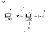
- FIG. 1 shows the image processing apparatus achieved in an embodiment of the present invention.
- the image processing apparatus is constituted with a personal computer 1.
- the personal computer 1 which is connected with a digital camera 2, a recording medium 3 such as a CD-ROM, another computer 4 and the like, is able to receive various types of image data.
- the personal computer 1 executes the image processing to be explained below on the image data provided thereto.
- the personal computer 1 is connected to the computer 4 via an electronic communication network 5, which may be the Internet.
- the program that enables the computer 1 to execute the image processing is provided in a recording medium such as a CD-ROM or by another computer via the Internet or another electronic communication network connected to the personal computer in a manner similar to that shown in FIG. 1, and the program thus provided is installed within the personal computer 1.
- the personal computer 1 comprises a CPU (not shown) and its peripheral circuits (not shown). The installed program is executed by the CPU.
- the program to be provided via the Internet or another electronic communication network is converted to and transmitted as a signal on a carrier wave which is carried through the electronic communication network, i.e., a transmission medium.
- the program can be distributed as a computer-readable computer program product adopting any of various modes including a recording medium and a carrier wave.
- FIG. 2 presents a flowchart of the image processing executed by the personal computer 1 in the first embodiment.
- step S1 linear RGB image data are input.
- step S2 the input data are converted to a uniform noise and pseudo-uniform color space.
- step S3 noise removal processing is executed.
- step S4 the color space undergoes reverse conversion.
- step S5 the image data, having undergone the processing, are output. The following is a detailed explanation of the processing executed in each step.
- the linear RGB image data input in step S1 are RGB colorimetric system data that express a linear gradation.
- the RGB colorimetric system data which have been obtained by capturing an image with, for instance, an image sensor (an image-capturing device) such as a CCD equipped with color filters disposed in a Bayer array, will have undergone various types of interpolation processing so that each pixel holds color information corresponding to the R component, the G component and the B component.
- Linear gradation data are gradation data achieving linearity relative to the light intensity, which assume color information values inproportion to the amount of received light. Data having undergone gamma correction should be structured back into the linear gradation data format before image processing. Such image data may be obtained by capturing an image with the digital camera 2 or another imaging device.
- step S2 the three stimulus values R, G and B in the linear gradation data are converted to values in a color space that constitutes the uniform noise and pseudo-uniform color space.
- This space is defined in the description of the embodiment as a space obtained by modifying the uniform color space L*a*b* in the related art in consideration of noise uniformity and, for the sake of convenience, is referred to as L ⁇ a ⁇ b ⁇ .
- the data are converted to XYZ colorimetric system data, which are normally used when defining a uniform color space.
- the conversion expression will vary depending upon the spectral sensitivity distribution characteristics of the color filters used in the image sensor from which the data are input.
- CIE RGB colorimetric system data with the reference stimuli assuming values of 700.0 nm for R, 546.1 nm for G and 435.8 nm for B in a single spectrum may be converted to CIE XYZ colorimetric system data, as expressed below.
- B Z + 0.0565 ⁇ G + 5.5943 ⁇ B
- the RGB values having been reverted to linear gradation data may be converted to XYZ values as expressed below.
- X 0.4124 ⁇ R + 0.3576 ⁇ G + 0.1805 ⁇ B
- Y 0.2126 ⁇ R + 0.7152 ⁇ G + 0.0722 ⁇ B
- Z 0.0193 ⁇ R + 0.1192 ⁇ G + 0.9505 ⁇ B
- X0, Y0 and Z0 in the expressions above each represent a value determined in correspondence to the illuminating light.
- X0, Y0 and Z0 may assume values 95.045,100.00 and 108.892 respectively in a 2° visual field under standard light D65.
- the nonlinear gradation conversion function f( ) is defined in (10) below.
- the origin point and the saturation point may be normalized by using the following expression.
- f t t + ⁇ - ⁇ 1 + ⁇ - ⁇
- ⁇ in the expression above represents an offset signal applied to the linear gradation signal.
- the offset signal assumes the value of zero or a positive value, and its value increases as the imaging sensitivity becomes higher. While ⁇ assumes a value determined based upon the level of dark noise in the sensor, a value very close to zero, for instance, will be assumed when the ISO value is approximately 100 and a value approximately equal to 0.05 will be assumed in correspondence to an ISO value of approximately 6400.
- Conversion expressions (7), (8) and (9) are similar to the conversion expressions used to convert the XYZ space to the uniform color space CIE L*a*b*.
- the conversion expressions differ in that while the conversion expressions used to convert data to the uniform color space CIE L*a*b* each assume a power function with a fractional power of 1/3, expressions (7), (8) and (9) each assume a power function with a fractional power of 1/2.
- Another difference lies in that the offset signal s, which is not factored in the conversion expressions used in the conversion to the uniform color space CIE L*a*b*, is incorporated in expressions (7), (8) and (9).
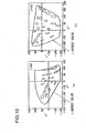
- the plurality of small McAdams deviation ellipses in the figures achieve substantial uniformity, indicating that both the CIE L*a*b* space and the CIE L*u*v* color space are uniform color spaces.
- the uniformity of McAdams deviation ellipses is achieved in a manner similar to those shown in FIGS. 10 (a) and 10(b).
- the initial linear gradation RGB signals each contain random noise constituted with two elements, i.e., shot noise, which is in proportion to the square root of the signal value and dark noise in the image sensor and the circuit system, which is not dependent on the signal value.
- shot noise which is in proportion to the square root of the signal value and dark noise in the image sensor and the circuit system, which is not dependent on the signal value.
- ⁇ R representing the shot noise in an R signal
- ⁇ (constant) representing the dark noise in the R signal
- the total noise quantities ⁇ R, ⁇ G and ⁇ B corresponding to R, G and B can be expressed as below. It is to be noted that the expressions below do not include any constant multiple term. Since ⁇ is a constant, it is notated by adding ⁇ in the expressions for the sake of convenience.
- Japanese Patent Application No. 2004-200890 discloses that when signals contain both shot noise and the dark noise, a uniform noise space can be realized by applying an offset signal corresponding to the quantity of dark noise prior to the square root gradation conversion.
- the L ⁇ a ⁇ b ⁇ expressing with the luminance (brightness) and the chrominances (color differences), which are defined as the results of linear conversion executed on X', Y' and Z' achieving noise uniformity, too, is a uniform noise space.
- errors ⁇ L ⁇ ⁇ a ⁇ and ⁇ b ⁇ corresponding to L ⁇ , a ⁇ and b ⁇ expressed in (30), (31) and (32) respectively can be calculated as in (33), (34) and (35) each indicating a constant value.
- each plane in the uniform color space L ⁇ a ⁇ b ⁇ having undergone the processing to achieve noise uniformity undergoes noise removal processing, executed with a noise filter by referencing an index representing the noise quantities substantially in a single profile.
- the noise filters in the related art include the bilateral filter (non-patent reference 2).
- a bilateral filter different from the bilateral filter in the related art is utilized in the embodiment. Namely, smoothing processing is executed so as to smooth signal components fluctuating over a range substantially equal to the range of noise as the signal difference quantity and the distance ratio mutually affect each other within a predetermined range.
- the bilateral filter in the related art is an adaptive filter whereby both the spatial distance and the pixel value difference are both taken into consideration as arguments (variables, parameters).
- the filter is referred to as a bilateral filter since it assumes two arguments.
- the weighting coefficient in the filter is represented by the product of the weighting coefficient w_photo [V'-V] of the photometric term in which the pixel value difference (V'-V) alone is used as an argument and the weighting coefficient w_geometric[r'-r] in the geometric term in which the distance (r'-r) alone is used as an argument.
- an unseparated weighting-type bilateral filter in which the weighting coefficient cannot be separated into the photometric term and the geometric term instead of the separated weighting -type bilateral filter in the related art in which the weighting coefficient can be separated into the photometric term and the geometric term, is utilized as the noise removal filter.
- the bilateral filter in the related art assumes a weighting coefficient represented by the product of two exponential functions each assuming one of the two arguments as an exponent thereof.
- the filter used in the embodiment assumes a weighting coefficient represented by a single exponential function in which the value indicated by the product of the two arguments is handled as a single exponent.
- the filtering processing is executed separately on the L ⁇ plane, the a ⁇ plane and the b ⁇ plane.
- the noise component includes the full range of frequency components, from short cycles to long cycles.
- rth should be set to approximately 20, i.e., the filtering size needs to match a pixel range of approximately 80 x 80 pixels. Even through such wide-range filtering, the noise can be removed effectively without destroying the image structure since the two factors, i.e., the pixel value difference and the spatial distance, are both taken into consideration.
- the weighting coefficient is calculated only after taking the product of the two arguments, i.e., the pixel value difference and the distance.
- the unseparated weighting-type filter in the embodiment with the spatial distance argument made to favorably affect the pixel value difference argument ultimately generates a finite weighting coefficient so as to achieve effective noise removal, unlike in the separated weighting-type filter in the related art, through which effective noise removal cannot be executed when a sudden decrease in the weighting coefficient in the photometric term becomes a dominant factor.
- the filtering intensity is reduced drastically, which tends to allow color mottling noise over long cycles to remain as color artifacts.
- the unseparated weighting-type filter in the embodiment sustains the desired filtering intensity level even when the distance between pixels is significant, as long as the pixel value difference does not exceed the extent of noise fluctuation and thus, is capable of clean noise removal.
- ⁇ th in expressions (36), (37) and (38) should assume a value ⁇ 2 times the standard deviation measured in the uniform noise and pseudo-uniformcolor space by photographing a uniform surface.
- the standard deviation assumes a constant value regardless of the luminance level.
- the noise characteristics of the input image data can be profiled as a single representative value by using this standard deviation.
- the standard deviation measured in the uniform noise space of the uniform plane image data can be utilized as the representative value when evaluating the noise characteristics of the input image.
- the filtering processing described above is executed by using this representative value. The use of such a filter is greatly facilitated in a uniform color space.
- ⁇ th will assume different values in correspondence to various sensors, ⁇ th will assume a value approximately equal to 1 in correspondence to an ISO value of approximately 100 and will take on a value of 10 to 15 in correspondence to an ISO value of approximately 6400, when there are 256 gradations.
- noise removal is executed on the luminance component so as to reduce the grainy fluctuations while retaining the initial image structure such as edges and texture.
- the noise in each chrominance component is removed by eliminating color mottling noise and color moiré while retaining the initial color structure and assuring a desired level of color reproducibility.
- the level of noise removal for the luminance component may be adjusted to suit the individual user's preferences, since sharp definition can be sustained only by sacrificing the complete prevention of grainy fluctuations.
- noise removal may be executed by individually applying a ⁇ filter instead of the bilateral filter to the L ⁇ plane, the a ⁇ plane and the b ⁇ plane.
- noise removal may be executed by utilizing a unilateral filter, in which the pixel value difference alone is designated as an argument.
- step S4 in FIG. 2 the L ⁇ a ⁇ b ⁇ color space is converted back to the linear gradation RGB color space.
- the reverse-conversion may be executed by reversing the process defined in expressions (1), (2) and (3), expressions (7), (8) and (9) and the like.
- step S5 in FIG. 2 the image data from which the noise has been removed are output.
- processing for converting the image data to a standard color space optimal for display, such as the sRGB color space, may be executed.
- the linear gradation image data in the RGB color space are first converted to image data in a uniform color space in which noise uniformity is also achieved.
- the image data in the uniform color space are then filtered for noise removal.
- the image data having undergone the noise removal are reverse-converted to image data in the initial linear gradation RGB color space and are output.
- the filter cannot assure effective color noise removal and desirable color reproducibility at once due to the uncertainty principle in the quantum mechanics if the filter is used to remove noise manifesting over a wide range such as color mottling noise. While a high level of color reproducibility is assured by using a uniform color space, uniformity in the noise is not achieved in the uniform color space. Thus, the noise processing is bound to be complicated, which, in turn, is bound to lower the noise removal capability.
- an image photographed at a high sensitivity level e.g., ISO 3200 or ISO 6400
- the fluctuation width of the dark noise will be emphasized over an area such as a flat red area due to the 1/3 gamma characteristics without offset.
- the emphasized dark noise fluctuation width will not be contained within the target width over which an intense noise removal effect is achieved, resulting in a look of graininess remaining uncorrected.
- a high level of color mottling noise removal performance will not be assured.
- the removal of color noise such as color artifacts and a high level of color reproducibility can be assured in an optimal combination.
- the uniform noise and pseudo-uniform color space achieved in the embodiment differs from the color space L*a*b* in the related art in that an offset signal is applied to the data assuming R, G and B stimulus values and in that the non-linear gradation conversion is executed by using power functions with a fractional power of 1/2 instead of a fractional power of 1/3.
- the offset signal which lessens the extent of steepness in the increase of the square root over dark areas, is used to ensure that the dark noise remains unemphasized.
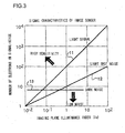
- FIG. 3 is a diagram provided to facilitate an explanation of the signal characteristics observed at the image sensor.
- the imaging plane illuminance is indicated along the horizontal axis and the number of electrons in the signal is indicated along the vertical axis.
- a straight line 11, representing a light signal indicates that the light signal level (the number of electrons) increases in proportion to the quantity of incident light.
- a straight line 12, representing light shot noise indicates that the noise (the number of electrons) increases in proportion to the square root of the amount of incident light.
- a straight line 13, representing dark noise (thermal electrons) indicates that presence of the noise (the quantity of electrons) is not affected by the amount of incident light.
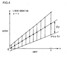
- FIGS. 4 through 7 each schematically illustrate a uniform noise space.
- FIG. 4 presents a graph of linear gradation.
- the quantity x of light input to the image sensor is indicated along the horizontal axis, whereas the signal output y from the image sensor is indicated along the vertical axis.
- ⁇ y indicating the fluctuation width of the random noise made up with the shot noise and the dark noise, increases by a factor of the square root of the input x excluding the constant component corresponding to the dark noise.
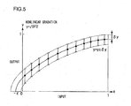
- the offset ⁇ explained earlier is incorporated in the graph presented in FIG. 5.
- the random noise ⁇ y representing the sum of the shot noise and the dark noise, having undergone the offset-incorporated square root gradation conversion, assumes a constant value regardless of the input value. This proves that through the offset-incorporated square root gradation conversion, a uniform noise space is realized for the random noise representing the sum of the shot noise and the dark noise.
- FIG. 6 shows how the cube root gradation conversion is executed to convert image data to the uniform color space CIE L*a*b* in the related art.
- FIG. 6 shows how the cube root gradation conversion is executed to convert image data to the uniform color space CIE L*a*b* in the related art.
- the random noise ⁇ y representing the sum of the shot noise and the dark noise decreases as the input value increases, i.e., the random noise ⁇ y does not remain constant, in the uniform color space CIE L*a*b* in the related art.
- a uniform noise space with regard to the random noise is not realized through the uniform color space CIE L*a*b* in the related art.
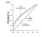
- FIG. 7 shows the input/output characteristics observed in the linear gradation space, the square root gradation space and the offset-incorporated square root gradation space.
- the linear gradation signal input value x is indicated along the horizontal axis and the output value y is indicated along the vertical axis.
- a straight line 21 represents the input/output characteristics observed in the linear conversion
- a curve 22 represents the input/output characteristics observed in the square root space conversion
- a curve 23 represents the input/output characteristics observed in the offset-incorporated square root space conversion.
- the curve 23 represents the processing expressed in (10) explained earlier.
- the slope of the curve 22 becomes steeper over an area (e.g., 0 ⁇ x ⁇ 0.1) where the linear input value is small and the dark noise is dominant, i.e., over the low luminance area.
- the slope does not become steep even over an area where dark noise is dominant (e.g., 0 ⁇ x ⁇ 0.1).
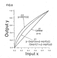
- FIG. 8 shows the input/output characteristics observed in the linear gradation space, the square root gradation space and the gradation space expressed in (11).
- a straight line 21 and a curve 22 are identical to those in FIG. 7 and represent the input/output characteristics observed in the linear conversion and the input/output characteristics observed in the square root space conversion.
- a curve 31 is obtained by normalizing the origin point and the saturation point as expressed in (11).
- the data in the linear gradation XYZ space are converted to the nonlinear gradation L ⁇ a ⁇ b ⁇ space assuming a uniform noise and a perceptive attribute with uniform color distribution in the first embodiment.
- nonlinear conversion is first executed for purposes of achieving noise uniformity on R, G and B stimulus values having been linearly input and then linear conversion is executed so as to generate a uniform color space.
- the data still at the RGB stage undergo offset-incorporated square root conversion so as to achieve uniform noise and then the data are defined simply through linear conversion to the XYZ space and through linear conversion to visual perception characteristics. Better connection with high-accuracy interpolation processing executed in a uniform noise space can be assured by adopting this method.
- FIG. 9 presents a flowchart of the image processing executed by the personal computer 1 in the second embodiment.
- step S11 linear RGB image data, e.g., image data obtained by capturing an image at an image sensor equipped with color filters in a Bayer array, are input. At this stage, the data are yet to undergo interpolation processing and thus, each of the pixels holds color information corresponding to the R-component, the G-component or the B-component.
- step S12 the data are converted to a uniform noise space.
- step S13 the interpolation processing is executed.
- step S14 linear conversion is executed on the data so as to convert them to a pseudo-uniform color space, thereby achieving a uniform noise and pseudo-uniform color space.
- step S15 noise removal processing is executed.
- step S16 the color space is reverse-converted.
- stepS17 the image data having undergone the processing are output. The following is a detailed explanation of the processing executed in each step.
- the linear RGB image data input in step S11 are RGB colorimetric system data expressed by using a linear gradation.
- RGB colorimetric system data which may have been obtained by capturing an image with an image sensor such as a CCD equipped with color filters disposed in, for instance, a Bayer array, contain R-color component information, G-color component information or B-color component information in correspondence to each of the pixels. These linear RGB image data are yet to undergo the interpolation processing.
- step S12 the data are converted to a uniform noise space. Uniformity in the noise containing shot noise and dark noise in the sensor and the circuit system can be achieved by applying an offset signal to the RGB linear gradation data so as to convert the data to data with square root gradation characteristics.
- the linear RGB image data are converted to nonlinear RGB image data, as expressed in (39), (40) and (41) below with the offset signal s.
- step S13 the image data having been converted to the uniform noise space undergo interpolation processing.
- each pixel only holds color information corresponding to one of the color components, i.e., the R-component, the G-component or the B-component, as explained earlier. Accordingly, color information corresponding to the missing color components is generated through interpolation processing for each pixel.
- Various interpolation processing methods have been proposed to date and the optimal method among them to suit the particular needs of the embodiment should be adopted. It is to be noted that very accurate results can be achieved more easily by assuring noise uniformity in the interpolation processing as well.
- the matrix coefficient used for this conversion is the same matrix coefficient as that used in the conversion of the CIE RGB colorimetric system data to CIE XYZ colorimetric system data, both defined as linear gradation data.
- a matrix having been corrected to a slightly further extent may be used, instead.
- the nonlinear X'Y'Z' data are further converted to a space achieving pseudo uniform color perception, as expressed in (45), (46) and (47) below.
- this space is referred to as an L#a#b# space.
- a uniform noise and pseudo-uniform color space is thus realized. Since noise uniformity, whereby the noises is not dependent on the gradation, is assured in advance while the data are at the R'G'B' stage, the X'Y'Z' data and the L#a#b# data, resulting from the linear conversion of the data in the uniform noise space, too, are data in uniform noise spaces that are not dependent upon the gradation.
- the noise removal processing is executed as in the first embodiment.
- step S16 the L#a#b# color space is converted back to a linear gradation RGB color space.
- the reverse-conversion may be executed by reversing the process defined in the expressions described earlier.
- the data in the L#a#b# color space may be converted to data in another color space as desired.
- step S17 the image data having undergone the noise removal are output.
- the data will have been converted to a uniform color space by first converting them to X'Y'Z' data defined with a simulated nonlinear gradation instead of converting the data to XYZ data defined with the standard linear gradation.
- the data in the uniform noise space are allowed to shift directly into the uniform noise and uniform color space, resulting in a reduction in the number of arithmetic operations needed to be executed for color space conversion and assuring even better connection with the interpolation processing.
- the present invention may be adopted in conjunction with the CIECAM97 data, CIECAM02 data, iCAM data and the like having been disclosed more recently, as well as the L*u*v* data, the Hunter Lab data and the LABHNU data, since they are each data, which can be basically linearly converted to/from the XYZ colorimetric system data and are data in a color system defined through conversion from linear gradation to nonlinear gradation.
- the color space according to the present invention is referred to as a "pseudo-uniform color space".
- the word "pseudo" has been selected since a space similar to the L*a*b* space known as a uniform color space in the related art is generated according to the present invention.
- a different uniform color space is generated in correspondence to a given imaging sensitivity level.
- the pseudo-uniform color space according to the present invention may be regarded as an even more accurate uniform color space compared to the uniform color space in the related art.
- the filter used in the embodiments is defined as in (36) ⁇ (38), the present invention is not limited to this example.
- the weighting coefficient may be set to 0 (if the difference is greater) or 1 (if the difference is smaller) and the average value may be calculated by using the pixel values in conjunction with which the weighting coefficient is set to 1.
- the present invention is not limited to this example and the processingmaybe executed in an imaging apparatus such as a camera or another type of apparatus.
- the present invention may be adopted in all types of apparatuses in which image data are handled.
Landscapes
- Engineering & Computer Science (AREA)
- Multimedia (AREA)
- Signal Processing (AREA)
- Image Processing (AREA)
- Facsimile Image Signal Circuits (AREA)
- Color Television Image Signal Generators (AREA)
- Color Image Communication Systems (AREA)
Abstract
Description
- The present invention relates to an image processing method to be adopted to convert image data to a color space optimal for removal of noise from the image and color reproduction.
- There is an image processing method disclosed in the related art (see patent reference 1) adopting the concept of the uniform noise space achieved through square root gradation conversion so as to convert shot noise, which increases by a factor of the square root of the signal intensity, to noise remaining constant relative to the signal intensity. This method, through which the noise fluctuation width, i.e., the standard deviation, is indicated by a single representative value regardless of the gradation, facilitates noise profiling.
- For instance, if image data are filtered in a uniform noise space with a σ filter (non-patent reference 1) through which noise is removed by averaging pixel values whose differences are equal to or less than a constant multiple of the standard deviation σ or with a bilateral filter (nonpatent reference 2) through which noise is removed through Gaussian blur by using the ratios of pixel value differences relative to the standard deviation σ as an argument in conjunction with spatial Gaussian blur, the noise can be accurately removed in a manner optimal for the particular image structure, since the standard deviation value is not dependent upon the luminance. If the noise is to be removed without using such a uniform noise space, a process of generating a noise profile by determining the standard deviation in correspondence to each luminance level needs to be executed as disclosed in
patent reference 2. - A color space in which the luminance and chrominance are expressed by taking into consideration the human visual system, is often used in image processing. Under normal circumstances, a uniform color space such as L*a*b* is routinely used, since such a uniform color space in which a color signal is expressed in a manner closer to human visual perception, is considered to assure superior color reproduction.
-
- Patent reference 1:
Japanese Laid Open Patent Publication No.H7-92588 - Patent reference 2:
US Patent Publication No. 5923775 - Nonpatent reference 1: J. S. Lee "Digital Image Smoothing and the Sigma Filter" Computer Vision, Graphics and Image Processing, Vol. 24, pp 255 ~ 269, 1983
- Nonpatent reference 2:C. Tomasi et al. "Bilateral Filtering for Gray and Color Images," Proceedings of the 1998 IEEE International Conference of Computer Vision, Bombay, India
- However, there is still an issue to be addressed with regard to the uniform noise space technologies proposed in the related art in that the aspect of color uniformity is not taken into consideration. It must also be kept in mind that while the aspect of color uniformity is factored in a uniform color space proposed in the related art, the aspect of noise uniformity is not taken into consideration in the uniform color space technologies in the related art. For this reason, the fully realized performance can be achieved with regard to only either one of the factors taken into consideration in a given space.
- According to the 1st aspect of the present invention, an image processing method, comprises: inputting color image data obtained by capturing an image at a given imaging sensitivity level; and converting the color image data to a specific uniform color space determined in correspondence to the imaging sensitivity level.
According to the 2nd aspect of the present invention, in the image processing method according to the 1st aspect, it is preferred that when converting the color image data to the uniform color space, gradation conversion characteristics based upon which the color image data are converted to the uniform color space are altered in correspondence to the imaging sensitivity level.
According to the 3rd aspect of the present invention, in the image processing method according to the 2nd aspect, it is preferred that the gradation conversion characteristics are nonlinear gradation conversion characteristics.
According to the 4th aspect of the present invention, an image processing method for converting image data having been input, which are expressed by a set of stimulus values having linear gradation characteristics relative to light intensity, to the color signals indicating a perceptive attribute by executing a specific type of nonlinear gradation conversion on the stimulus values assumed in the input image data, comprises: executing the conversion from linear gradation to nonlinear gradation in a state in which an offset signal is applied to each of the stimulus values assumed in the image data.
According to the 5th aspect of the present invention, in the image processing method according to the 4th aspect, it is preferred that through the specific type of nonlinear gradation conversion, the image data are converted to color signals indicating a perceptive attribute that achieves a pseudo-uniform color space.
According to the 6th aspect of the present invention, in the image processing method according to the 4th or the 5th aspect, it is preferred that the specific type of nonlinear gradation conversion is nonlinear gradation conversion having substantially square root characteristics.
According to the 7th aspect of the present invention, in the image processing method according to any one of the 4th through 6th aspects, it is preferred that the offset signal assumes a value of 0 or a positive value.
According to the 8th aspect of the present invention, in the image processing method according to any one of the 4th through 7th aspects, it is preferred that when applying the offset signal to each of the stimulus values assumed in the image data, a value of the offset signal is adjusted in correspondence to the imaging sensitivity level with which the input image data have been captured.
According to the 9th aspect of the present invention, in the image processing method according to any one of the 4th through 8th aspects, it is preferred that a specific width of the color signals resulting from the conversion is designated as a representative value representing noise characteristics of the input image data.
According to the 10th aspect of the present invention, in the image processing method according to the 9th aspect, it is preferred that the specific signal width is determined by capturing an image of a uniform surface, converting image data of the uniform plane to color signals indicating a perceptive attribute through the specific type of nonlinear gradation conversion and then ascertaining a standard deviation of the image data of the uniform plane having undergone the conversion.
According to the 11th aspect of the present invention, in the image processing method according to the 9th or 10th aspect, it is preferred that noise removal processing is executed by utilizing the representative value of the noise characteristics in a color space containing the color signals resulting from the conversion.
According to the 12th aspect of the present invention, in the image processing method according to any one of the 4th through 11th aspects, it is preferred that the input image data are image data expressed with three stimulus values with X, Y and Z constituting reference color stimuli.
According to the 13th aspect of the present invention, in the image processing method according to any one of the 4th through 11th aspects, it is preferred that: the input image data are image data expressed with three stimulus values with R, G and B constituting reference color stimuli; the image data expressed with the three stimulus values with R, G and B constituting the reference color stimuli are converted to image data with three stimulus values X, Y and Z expressed through linear coupling of the reference color stimuli; and the X, Y and Z resulting from the conversion are then converted to the perceptive attribute.
According to the 14th aspect of the present invention, in the image processing method according to any one of the 4th through 11th aspects, it is preferred that: the input image data are image data expressed with three stimulus values with R, G and B constituting reference color stimuli; and the three stimulus values R, G and B first undergo nonlinear gradation conversion while still at an RGB stage and are then converted to the perceptive attribute.
According to the 15th aspect of the present invention, an image processing method, comprises: inputting color image data having linear gradation characteristics; and converting the input color image data to a uniform noise space through nonlinear gradation conversion and also converting the color image data to a uniform color space by using a predetermined conversion expression.
According to the 16th aspect of the present invention, in the image processing method according to the 15th aspect, it is preferred that the input color image data, with an offset signal applied thereto, are converted to the uniform noise space through the nonlinear gradation conversion.
According to the 17th aspect of the present invention, in the image processing method according to the 15th or 16th aspect, it is preferred that: the color image data are converted to an XYZ space defined by X, Y, Z stimulus values; and as the color image data are converted from the XYZ space to the uniform color space, the color image data are converted to the uniform noise space through a square root gradation conversion instead of a cube root gradation conversion.
According to the 18th aspect of the present invention, a computer-readable computer program product comprises an image processing program that enables a computer or an image processing apparatus to execute an image processing method according to any one of the 1st through 17th aspects.
According to the 19th aspect of the present invention, it is preferred that the computer program product according to the 18th aspect is a computer-readable recording medium having recorded therein the image processing program.
According to the 20th aspect of the present invention, an image processing apparatus comprises a control device that executes an image processing method according to any one of the 1 through 17. - The present invention adopting the structure described above achieves the following advantages. Since a space achieving both noise uniformity and color uniformity is generated, the noise and the color can be handled very easily, which, in turn, facilitates various types of high-performance image processing. In addition, desirable color noise inhibition and desirable color reproducibility can both be assured by executing the noise removal processing on a chrominance component.
-
- (FIG. 1) An image processing apparatus achieved in an embodiment of the present invention
- (FIG. 2) A flowchart of the image processing executed in the first embodiment
- (FIG. 3) A diagram of the signal characteristics that may be observed at the image sensor
- (FIG. 4) A graph of the linear gradation
- (FIG. 5) A graph obtained by executing non-linear gradation (square root gradation) conversion on the graph of linear gradation y = x)
- (FIG. 6) Cube root gradation conversion executed in the related art when converting image data to the uniform color space CIE L*a*b*
- (FIG. 7) The input/output characteristics observed in a linear gradation space, a square root gradation space and an offset-incorporated square root gradation space
- (FIG. 8) The input/output characteristics observed in a linear gradation space, a square root gradation space and a gradation space expressed in (11)
- (FIG. 9) A flowchart of the image processing executed in a second embodiment
- (FIG. 10) The McAdams deviation ellipses in the chromaticity diagrams for the CIE L*a*b* color space and the CIE L*u*v* color space in the related art.
- FIG. 1 shows the image processing apparatus achieved in an embodiment of the present invention. The image processing apparatus is constituted with a
personal computer 1. Thepersonal computer 1, which is connected with adigital camera 2, arecording medium 3 such as a CD-ROM, anothercomputer 4 and the like, is able to receive various types of image data. Thepersonal computer 1 executes the image processing to be explained below on the image data provided thereto. Thepersonal computer 1 is connected to thecomputer 4 via anelectronic communication network 5, which may be the Internet. - The program that enables the
computer 1 to execute the image processing is provided in a recording medium such as a CD-ROM or by another computer via the Internet or another electronic communication network connected to the personal computer in a manner similar to that shown in FIG. 1, and the program thus provided is installed within thepersonal computer 1. Thepersonal computer 1 comprises a CPU (not shown) and its peripheral circuits (not shown). The installed program is executed by the CPU. - The program to be provided via the Internet or another electronic communication network is converted to and transmitted as a signal on a carrier wave which is carried through the electronic communication network, i.e., a transmission medium. Namely, the program can be distributed as a computer-readable computer program product adopting any of various modes including a recording medium and a carrier wave.
- The image processing executed in the
personal computer 1 is now explained. FIG. 2 presents a flowchart of the image processing executed by thepersonal computer 1 in the first embodiment. In step S1, linear RGB image data are input. In step S2, the input data are converted to a uniform noise and pseudo-uniform color space. In step S3, noise removal processing is executed. In step S4, the color space undergoes reverse conversion. In step S5, the image data, having undergone the processing, are output. The following is a detailed explanation of the processing executed in each step. - The linear RGB image data input in step S1 are RGB colorimetric system data that express a linear gradation. The RGB colorimetric system data, which have been obtained by capturing an image with, for instance, an image sensor (an image-capturing device) such as a CCD equipped with color filters disposed in a Bayer array, will have undergone various types of interpolation processing so that each pixel holds color information corresponding to the R component, the G component and the B component. Linear gradation data are gradation data achieving linearity relative to the light intensity, which assume color information values inproportion to the amount of received light. Data having undergone gamma correction should be structured back into the linear gradation data format before image processing. Such image data may be obtained by capturing an image with the
digital camera 2 or another imaging device. - In step S2, the three stimulus values R, G and B in the linear gradation data are converted to values in a color space that constitutes the uniform noise and pseudo-uniform color space. This space is defined in the description of the embodiment as a space obtained by modifying the uniform color space L*a*b* in the related art in consideration of noise uniformity and, for the sake of convenience, is referred to as L^a^b^.
- First, the data are converted to XYZ colorimetric system data, which are normally used when defining a uniform color space. The conversion expression will vary depending upon the spectral sensitivity distribution characteristics of the color filters used in the image sensor from which the data are input. For instance, CIE RGB colorimetric system data with the reference stimuli assuming values of 700.0 nm for R, 546.1 nm for G and 435.8 nm for B in a single spectrum may be converted to CIE XYZ colorimetric system data, as expressed below.


- In another example, when handling a color image ultimately expressed in an sRGB color space, the RGB values having been reverted to linear gradation data may be converted to XYZ values as expressed below.



- Next, the data in the linear gradation XYZ space are converted to a nonlinear gradation L^a^b^ space representing a perceptive attribute with a pseudo-uniform color distribution.


- X0, Y0 and Z0 in the expressions above each represent a value determined in correspondence to the illuminating light. For instance, X0, Y0 and Z0 may assume values 95.045,100.00 and 108.892 respectively in a 2° visual field under standard light D65. In addition, the nonlinear gradation conversion function f( ) is defined in (10) below. It is to be noted that the variable t, expressed as; t = (Y/Y0), t = (X/X0), t = (Z/Z0), assumes a value normalized based upon the maximum value representing the number of gradations for the X,Y and Z values so that the relationship expressed as 0 ≤ (Y/Y0) ≤ 1, 0 ≤ (X/X0) ≤1, 0 ≤ (Z/Z0) ≤ 1, are satisfied. It is also to be noted that the notation √A used in the description of the embodiment indicates the square root of A, i.e., rootA.

- If necessary, the origin point and the saturation point may be normalized by using the following expression.

- ε in the expression above represents an offset signal applied to the linear gradation signal. The offset signal assumes the value of zero or a positive value, and its value increases as the imaging sensitivity becomes higher. While ε assumes a value determined based upon the level of dark noise in the sensor, a value very close to zero, for instance, will be assumed when the ISO value is approximately 100 and a value approximately equal to 0.05 will be assumed in correspondence to an ISO value of approximately 6400. Identical results will be achieved regardless of the timing of the offset signal application, i.e., the same results will be obtained by applying the offset signal at the time of the nonlinear gradation conversion, applying the offset signal to the data indicating the X,Y and Z values or applying the offset signal to the data indicating the R, G and B values.
- Conversion expressions (7), (8) and (9) are similar to the conversion expressions used to convert the XYZ space to the uniform color space CIE L*a*b*. The conversion expressions differ in that while the conversion expressions used to convert data to the uniform color space CIE L*a*b* each assume a power function with a fractional power of 1/3, expressions (7), (8) and (9) each assume a power function with a fractional power of 1/2. Another difference lies in that the offset signal s, which is not factored in the conversion expressions used in the conversion to the uniform color space CIE L*a*b*, is incorporated in expressions (7), (8) and (9).
- For reference, an example of the conversion expressions used to convert the data in the XYZ space to those in the uniform color space CIE L*a*b* is presented below.


- An explanation is now given on how the uniform noise and pseudo-uniform color space can be realized by using conversion expressions (7), (8) and (9) above. The uniform color space achieved by adopting conversion expressions (7), (8) and (9) without modifying the definition of the CIE L*a*b* in the related art to a very significant extent is thus realized as a pseudo-uniform color space. In other words, the uniform color distribution ratios over discriminator meshes indicated by the McAdams deviation (deviatoric) ellipses in a chromaticity diagram are sustained without a major change except for over the dark areas where the gradation characteristics change greatly. FIG. 10(a) shows McAdams deviation ellipses in the chromaticity diagram corresponding to L* = 50 in the CIE L*a*b* color space in the related art and FIG. 10(b) shows McAdams deviation ellipses in the chromaticity diagram corresponding to L* = 50 in the CIE L*u*v* color space in the related art. The plurality of small McAdams deviation ellipses in the figures achieve substantial uniformity, indicating that both the CIE L*a*b* space and the CIE L*u*v* color space are uniform color spaces. In the uniform noise andpseudo-uniformcolor space achieved in the embodiment, too, the uniformity of McAdams deviation ellipses is achieved in a manner similar to those shown in FIGS. 10 (a) and 10(b).
- The other factor, i.e., the noise uniformity, is now described in further detail. The initial linear gradation RGB signals each contain random noise constituted with two elements, i.e., shot noise, which is in proportion to the square root of the signal value and dark noise in the image sensor and the circuit system, which is not dependent on the signal value. With √R representing the shot noise in an R signal and √ε (constant) representing the dark noise in the R signal, the total noise quantities δR, δG and δB corresponding to R, G and B can be expressed as below. It is to be noted that the expressions below do not include any constant multiple term. Since ε is a constant, it is notated by adding √ in the expressions for the sake of convenience. It is to be noted that
Japanese Patent Application No. 2004-200890 


- The conversion from the RGB colorimetric system to the XYZ colorimetric system may be expressed as in (18), (19) and (20) below in a rough approximation.



- Accordingly, bearing in mind the law of propagation of errors, δX, δY and δZ representing the noise quantities in the X signal, the Y signal and the Z signal respectively, may be written as below.


- If the nonlinear conversion portions are defined as expressed in (24), (25) and (26), it can be ascertained that individual noise quantities δX' δY' and δZ' each assume a constant value relative to the gradation as indicated in expressions (27), (28) and (29). Namely, by assuming ε corresponding to the dark noise for the offset quantity in the gradation conversion functions in expressions (24), (25) and (26), the noise quantities can be converted to the values representing constant noise relative to the luminance levels of X', Y' and Z' since the noise expansion/contraction occurring as the gradation conversion is executed and the luminance dependency of the initial noise quantities cancel each other out.


-


- As a result, the L^a^b^expressing with the luminance (brightness) and the chrominances (color differences), which are defined as the results of linear conversion executed on X', Y' and Z' achieving noise uniformity, too, is a uniform noise space. Namely, errors δL^ δa^ and δb^ corresponding to L^, a^ and b^ expressed in (30), (31) and (32) respectively can be calculated as in (33), (34) and (35) each indicating a constant value. In other words, a uniform color space in which noise uniformity is also achieved is realized.



-


- In step S3 in FIG. 2, each plane in the uniform color space L^a^b^ having undergone the processing to achieve noise uniformity undergoes noise removal processing, executed with a noise filter by referencing an index representing the noise quantities substantially in a single profile. The noise filters in the related art that may be utilized in such an application include the bilateral filter (non-patent reference 2). However, a bilateral filter different from the bilateral filter in the related art (non-patent reference 2), achieving an even higher level of performance as expressed in the following expressions, is utilized in the embodiment. Namely, smoothing processing is executed so as to smooth signal components fluctuating over a range substantially equal to the range of noise as the signal difference quantity and the distance ratio mutually affect each other within a predetermined range.
-
- (1) Luminance component L^

- (2) Chrominance component a^ and b^


- The bilateral filter in the related art (nonpatent reference 2) is an adaptive filter whereby both the spatial distance and the pixel value difference are both taken into consideration as arguments (variables, parameters). The filter is referred to as a bilateral filter since it assumes two arguments. The weighting coefficient in the filter is represented by the product of the weighting coefficient w_photo [V'-V] of the photometric term in which the pixel value difference (V'-V) alone is used as an argument and the weighting coefficient w_geometric[r'-r] in the geometric term in which the distance (r'-r) alone is used as an argument.
- However, there is a problem with such a bilateral filter in the related art in that since the weighting coefficients corresponding to the two arguments are handled separately, noise or color artifacts manifesting as projecting points remain uncorrected along edges or over color boundaries. Namely, situations in which the noise cannot be removed effectively tend to occur readily since the processing tends to be affected by a factor attributable to either of the arguments alone. For instance, over a color boundary area where the pixel value difference |V'-V| is assumed to increase abruptly, w_photometric [V'-V] assumes a drastically reduced value. As a result, regardless of how close to 1 the value assumed for w_geometric[r'-r] is, the value is disregarded and the noise initially present over the color boundary area cannot be removed.
- In the embodiment, an unseparated weighting-type bilateral filter in which the weighting coefficient cannot be separated into the photometric term and the geometric term, instead of the separated weighting -type bilateral filter in the related art in which the weighting coefficient can be separated into the photometric term and the geometric term, is utilized as the noise removal filter. To explain this point in more specific terms, the bilateral filter in the related art assumes a weighting coefficient represented by the product of two exponential functions each assuming one of the two arguments as an exponent thereof. The filter used in the embodiment, on the other hand, assumes a weighting coefficient represented by a single exponential function in which the value indicated by the product of the two arguments is handled as a single exponent. By assuming an integration range that is approximately twice rth, the arithmetic operation can be executed by fully taking into consideration the processing requirement for the Gaussian skirt while minimizing the scale of the arithmetic operation.
- The filtering processing is executed separately on the L^ plane, the a^ plane and the b^ plane. The noise component includes the full range of frequency components, from short cycles to long cycles. In order to be able to remove color mottling noise manifesting over long cycles, rth should be set to approximately 20, i.e., the filtering size needs to match a pixel range of approximately 80 x 80 pixels. Even through such wide-range filtering, the noise can be removed effectively without destroying the image structure since the two factors, i.e., the pixel value difference and the spatial distance, are both taken into consideration.
- In addition, the weighting coefficient is calculated only after taking the product of the two arguments, i.e., the pixel value difference and the distance. Thus, even when there is noise manifesting as projecting points, such as a color artifact, present over a steeply graded area, e.g., a color boundary area within the signal plane, the unseparated weighting-type filter in the embodiment, with the spatial distance argument made to favorably affect the pixel value difference argument ultimately generates a finite weighting coefficient so as to achieve effective noise removal, unlike in the separated weighting-type filter in the related art, through which effective noise removal cannot be executed when a sudden decrease in the weighting coefficient in the photometric term becomes a dominant factor.
- Furthermore, as the filtering processing is executed over a wider range with the separated weighting-type filter in the related art, the filtering intensity is reduced drastically, which tends to allow color mottling noise over long cycles to remain as color artifacts. In contrast, the unseparated weighting-type filter in the embodiment sustains the desired filtering intensity level even when the distance between pixels is significant, as long as the pixel value difference does not exceed the extent of noise fluctuation and thus, is capable of clean noise removal.
- σth in expressions (36), (37) and (38) should assume a value √2 times the standard deviation measured in the uniform noise and pseudo-uniformcolor space by photographing a uniform surface. In a uniform noise space, the standard deviation assumes a constant value regardless of the luminance level. Accordingly, the noise characteristics of the input image data can be profiled as a single representative value by using this standard deviation. Namely, the standard deviation measured in the uniform noise space of the uniform plane image data can be utilized as the representative value when evaluating the noise characteristics of the input image. The filtering processing described above is executed by using this representative value. The use of such a filter is greatly facilitated in a uniform color space. While σth will assume different values in correspondence to various sensors, σth will assume a value approximately equal to 1 in correspondence to an ISO value of approximately 100 and will take on a value of 10 to 15 in correspondence to an ISO value of approximately 6400, when there are 256 gradations.
- Through the method described above, noise removal is executed on the luminance component so as to reduce the grainy fluctuations while retaining the initial image structure such as edges and texture. The noise in each chrominance component is removed by eliminating color mottling noise and color moiré while retaining the initial color structure and assuring a desired level of color reproducibility. The level of noise removal for the luminance component may be adjusted to suit the individual user's preferences, since sharp definition can be sustained only by sacrificing the complete prevention of grainy fluctuations.
- It is to be noted that noise removal may be executed by individually applying a σ filter instead of the bilateral filter to the L^ plane, the a^ plane and the b^ plane. In addition, noise removal may be executed by utilizing a unilateral filter, in which the pixel value difference alone is designated as an argument.
- In step S4 in FIG. 2, the L^a^b^ color space is converted back to the linear gradation RGB color space. The reverse-conversion may be executed by reversing the process defined in expressions (1), (2) and (3), expressions (7), (8) and (9) and the like.
- In step S5 in FIG. 2, the image data from which the noise has been removed are output. At this point, processing for converting the image data to a standard color space optimal for display, such as the sRGB color space, may be executed.
- Through the process described above, the linear gradation image data in the RGB color space are first converted to image data in a uniform color space in which noise uniformity is also achieved. The image data in the uniform color space are then filtered for noise removal. Subsequently, the image data having undergone the noise removal are reverse-converted to image data in the initial linear gradation RGB color space and are output.
- The advantages of the embodiment explained above are now described. No matter how superior the adaptive filter used for noise removal may be with minimum image structure damage to the target image in a color space in the related art, the filter cannot assure effective color noise removal and desirable color reproducibility at once due to the uncertainty principle in the quantum mechanics if the filter is used to remove noise manifesting over a wide range such as color mottling noise. While a high level of color reproducibility is assured by using a uniform color space, uniformity in the noise is not achieved in the uniform color space. Thus, the noise processing is bound to be complicated, which, in turn, is bound to lower the noise removal capability.
- Forinstance, an image photographed at a high sensitivity level, e.g., ISO 3200 or ISO 6400, contains a great deal of dark noise. If such an image is processed in the uniform color space L*a*b*, the fluctuation width of the dark noise will be emphasized over an area such as a flat red area due to the 1/3 gamma characteristics without offset. In such a case, the emphasized dark noise fluctuation width will not be contained within the target width over which an intense noise removal effect is achieved, resulting in a look of graininess remaining uncorrected. For similar reasons, a high level of color mottling noise removal performance will not be assured.
- By using the color space achieved in the embodiment which may be referred to as a uniform noise and pseudo-uniform color space, the removal of color noise such as color artifacts and a high level of color reproducibility can be assured in an optimal combination.
- The uniform noise and pseudo-uniform color space achieved in the embodiment differs from the color space L*a*b* in the related art in that an offset signal is applied to the data assuming R, G and B stimulus values and in that the non-linear gradation conversion is executed by using power functions with a fractional power of 1/2 instead of a fractional power of 1/3. The offset signal, which lessens the extent of steepness in the increase of the square root over dark areas, is used to ensure that the dark noise remains unemphasized.
- It is to be noted that a similar effect will be achieved by applying the offset signal in conjunction with the power functions with a fractional power of 1/3 in the related art as well. Accordingly, although a fully uniform noise space may not be generated, a significant advantage is realized with regard to noise uniformity simply by applying the offset signal to the L*a*b* as defined in the related art while the data assumes RGB stimulus values or XYZ stimulus values.
- It would appear that the uniform color spaces in the relatedart, defined by CIE and the like, were conceived without taking into consideration how image signals constituting high sensitivity photographic data which would require noise removal processing and containing a significant quantity of dark noise, may be handled. An accurate uniform color display would not be realized by nonlinear gradation conversion, which would boost color signals in an area where the true signals were mostly buried in noise. It would be more desirable that when handling such high sensitivity photographic data, the color perception weight be slightly shifted to a lighter area where the color can be recognized more accurately. This shift is realized through the offset processing executed in the embodiment. It is assumed that when the image signals are processed in this uniform color space generated by taking into consideration the quantity of noise contained in the image, favorableimage processing results,closertohuman perception will be realized.
- In reference to FIGS. 3 through 8, the uniform noise space is explained in further detail. FIG. 3 is a diagram provided to facilitate an explanation of the signal characteristics observed at the image sensor. In the diagram in FIG. 3, which is presented on a log-log scale, the imaging plane illuminance is indicated along the horizontal axis and the number of electrons in the signal is indicated along the vertical axis. A
straight line 11, representing a light signal, indicates that the light signal level (the number of electrons) increases in proportion to the quantity of incident light. Astraight line 12, representing light shot noise, indicates that the noise (the number of electrons) increases in proportion to the square root of the amount of incident light. Astraight line 13, representing dark noise (thermal electrons), indicates that presence of the noise (the quantity of electrons) is not affected by the amount of incident light. - FIGS. 4 through 7 each schematically illustrate a uniform noise space. FIG. 4 presents a graph of linear gradation.
The quantity x of light input to the image sensor is indicated along the horizontal axis, whereas the signal output y from the image sensor is indicated along the vertical axis. The graph indicates that the output changes linearly as expressed as; y = x, in correspondence to the quantity of input light. δy, indicating the fluctuation width of the random noise made up with the shot noise and the dark noise, increases by a factor of the square root of the input x excluding the constant component corresponding to the dark noise. - FIG. 5 shows the results obtained by executing nonlinear gradation conversion (square root gradation conversion) on the graph of the linear gradation y = x. The offset ε explained earlier is incorporated in the graph presented in FIG. 5. As FIG. 5 indicates, the random noise δy representing the sum of the shot noise and the dark noise, having undergone the offset-incorporated square root gradation conversion, assumes a constant value regardless of the input value. This proves that through the offset-incorporated square root gradation conversion, a uniform noise space is realized for the random noise representing the sum of the shot noise and the dark noise. It is to be noted that FIG. 6 shows how the cube root gradation conversion is executed to convert image data to the uniform color space CIE L*a*b* in the related art. As FIG. 6 indicates, the random noise δy representing the sum of the shot noise and the dark noise decreases as the input value increases, i.e., the random noise δy does not remain constant, in the uniform color space CIE L*a*b* in the related art. In other words, a uniform noise space with regard to the random noise is not realized through the uniform color space CIE L*a*b* in the related art.
- FIG. 7 shows the input/output characteristics observed in the linear gradation space, the square root gradation space and the offset-incorporated square root gradation space. In FIG. 7, the linear gradation signal input value x is indicated along the horizontal axis and the output value y is indicated along the vertical axis. A
straight line 21 represents the input/output characteristics observed in the linear conversion, acurve 22 represents the input/output characteristics observed in the square root space conversion and a curve 23 represents the input/output characteristics observed in the offset-incorporated square root space conversion. The curve 23 represents the processing expressed in (10) explained earlier. - The slope of the
curve 22 becomes steeper over an area (e.g., 0 < x < 0.1) where the linear input value is small and the dark noise is dominant, i.e., over the low luminance area. Thus, if a fluctuation attributable to noise occurs in the input value, the fluctuation occurring on the input side will be amplified on the output side. In contrast, in the offset-incorporated square root gradation space (curve 23) achieved in the embodiment, the slope does not become steep even over an area where dark noise is dominant (e.g., 0 < x < 0.1). - FIG. 8 shows the input/output characteristics observed in the linear gradation space, the square root gradation space and the gradation space expressed in (11). A
straight line 21 and acurve 22 are identical to those in FIG. 7 and represent the input/output characteristics observed in the linear conversion and the input/output characteristics observed in the square root space conversion. Acurve 31 is obtained by normalizing the origin point and the saturation point as expressed in (11). - As expressed in (7), (8) and (9), the data in the linear gradation XYZ space are converted to the nonlinear gradation L^a^b^ space assuming a uniform noise and a perceptive attribute with uniform color distribution in the first embodiment. In the second embodiment, nonlinear conversion is first executed for purposes of achieving noise uniformity on R, G and B stimulus values having been linearly input and then linear conversion is executed so as to generate a uniform color space. Namely, the data still at the RGB stage undergo offset-incorporated square root conversion so as to achieve uniform noise and then the data are defined simply through linear conversion to the XYZ space and through linear conversion to visual perception characteristics. Better connection with high-accuracy interpolation processing executed in a uniform noise space can be assured by adopting this method.
- The structure of the image processing apparatus achieved in the second embodiment is similar to that adopted in the first embodiment having been described in reference to FIG. 1 and, accordingly, its explanation is omitted. FIG. 9 presents a flowchart of the image processing executed by the
personal computer 1 in the second embodiment. - In step S11, linear RGB image data, e.g., image data obtained by capturing an image at an image sensor equipped with color filters in a Bayer array, are input. At this stage, the data are yet to undergo interpolation processing and thus, each of the pixels holds color information corresponding to the R-component, the G-component or the B-component. In step S12, the data are converted to a uniform noise space. In step S13, the interpolation processing is executed. In step S14, linear conversion is executed on the data so as to convert them to a pseudo-uniform color space, thereby achieving a uniform noise and pseudo-uniform color space. In step S15, noise removal processing is executed. In step S16, the color space is reverse-converted. InstepS17, the image data having undergone the processing are output. The following is a detailed explanation of the processing executed in each step.
- The linear RGB image data input in step S11 are RGB colorimetric system data expressed by using a linear gradation. RGB colorimetric system data, which may have been obtained by capturing an image with an image sensor such as a CCD equipped with color filters disposed in, for instance, a Bayer array, contain R-color component information, G-color component information or B-color component information in correspondence to each of the pixels. These linear RGB image data are yet to undergo the interpolation processing.
- In step S12, the data are converted to a uniform noise space. Uniformity in the noise containing shot noise and dark noise in the sensor and the circuit system can be achieved by applying an offset signal to the RGB linear gradation data so as to convert the data to data with square root gradation characteristics. The linear RGB image data are converted to nonlinear RGB image data, as expressed in (39), (40) and (41) below with the offset signal s.
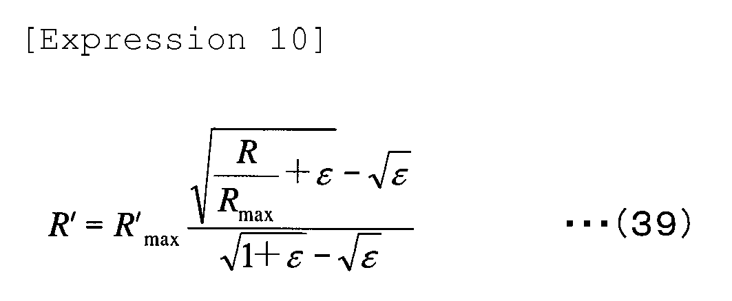

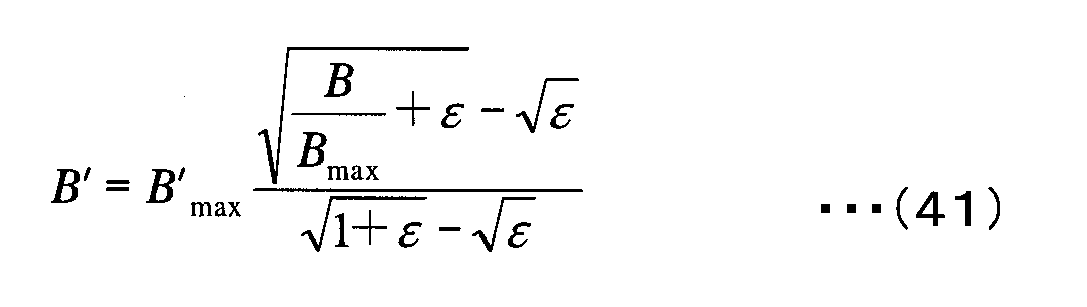
- should assume a value similar to that taken in the first embodiment.
- In step S13, the image data having been converted to the uniform noise space undergo interpolation processing. As explained earlier, in Bayer image data, for instance, each pixel only holds color information corresponding to one of the color components, i.e., the R-component, the G-component or the B-component, as explained earlier. Accordingly, color information corresponding to the missing color components is generated through interpolation processing for each pixel. Various interpolation processing methods have been proposed to date and the optimal method among them to suit the particular needs of the embodiment should be adopted. It is to be noted that very accurate results can be achieved more easily by assuring noise uniformity in the interpolation processing as well.
- The nonlinear R'G'B' data having undergone interpolation processing are then linearly converted to data in a X' Y' Z' space defined as nonlinear data in (42), (43) and (44) below.



- The matrix coefficient used for this conversion is the same matrix coefficient as that used in the conversion of the CIE RGB colorimetric system data to CIE XYZ colorimetric system data, both defined as linear gradation data. However, since the expressions presented above define conversion from nonlinear gradation data to nonlinear gradation data, a matrix having been corrected to a slightly further extent may be used, instead.
- The nonlinear X'Y'Z' data are further converted to a space achieving pseudo uniform color perception, as expressed in (45), (46) and (47) below. For the sake of convenience, this space is referred to as an L#a#b# space.


- A uniform noise and pseudo-uniform color space is thus realized. Since noise uniformity, whereby the noises is not dependent on the gradation, is assured in advance while the data are at the R'G'B' stage, the X'Y'Z' data and the L#a#b# data, resulting from the linear conversion of the data in the uniform noise space, too, are data in uniform noise spaces that are not dependent upon the gradation.
- The noise removal processing is executed as in the first embodiment.
- In step S16, the L#a#b# color space is converted back to a linear gradation RGB color space. The reverse-conversion may be executed by reversing the process defined in the expressions described earlier. Alternatively, the data in the L#a#b# color space may be converted to data in another color space as desired.
- In step S17, the image data having undergone the noise removal are output. In the embodiment, the data will have been converted to a uniform color space by first converting them to X'Y'Z' data defined with a simulated nonlinear gradation instead of converting the data to XYZ data defined with the standard linear gradation. This means that when the data output from the image sensor undergo interpolation processing and noise removal processing in succession, it is not necessary to reconvert the gradation in the uniform noise space used in the interpolation processing to linear gradation and then execute nonlinear gradation conversion on the data to convert the data to a uniform noise and uniform color space in preparation for the noise removal processing. In other words, the data in the uniform noise space are allowed to shift directly into the uniform noise and uniform color space, resulting in a reduction in the number of arithmetic operations needed to be executed for color space conversion and assuring even better connection with the interpolation processing.
- It is to be noted that an explanation has been given above in reference to the embodiments on an example in which a uniform noise space is achieved through square root gradation conversion executed by applying an offset signal. However, if the level of dark noise is low enough, a uniform noise space can be generated through the square root gradation conversion alone. At the same time, even through nonlinear gradation conversion that does not assume the square root gradation characteristics,the principal object, i.e., noise uniformity, can be achieved with the dark noise in the image sensor and the circuit system approximately taken into consideration, by simply executing an offset operation on RGB stimulus values or XYZ stimulus values.
- Accordingly, the present invention may be adopted in conjunction with the CIECAM97 data, CIECAM02 data, iCAM data and the like having been disclosed more recently, as well as the L*u*v* data, the Hunter Lab data and the LABHNU data, since they are each data, which can be basically linearly converted to/from the XYZ colorimetric system data and are data in a color system defined through conversion from linear gradation to nonlinear gradation.
- In the description of the embodiments, the color space according to the present invention is referred to as a "pseudo-uniform color space". The word "pseudo" has been selected since a space similar to the L*a*b* space known as a uniform color space in the related art is generated according to the present invention. However, it is to be noted that according to the present invention a different uniform color space is generated in correspondence to a given imaging sensitivity level. Thus, the pseudo-uniform color space according to the present invention may be regarded as an even more accurate uniform color space compared to the uniform color space in the related art.
- While the filter used in the embodiments is defined as in (36) ~ (38), the present invention is not limited to this example. For instance, depending upon whether or not the pixel value difference is greater than the profiled representative value σ, 2σ or the like, the weighting coefficient may be set to 0 (if the difference is greater) or 1 (if the difference is smaller) and the average value may be calculated by using the pixel values in conjunction with which the weighting coefficient is set to 1.
- While the processing is executed by the
personal computer 1 in the embodiments described above, the present invention is not limited to this example and the processingmaybe executed in an imaging apparatus such as a camera or another type of apparatus. In other words, the present invention may be adopted in all types of apparatuses in which image data are handled. - While the invention has been particularly shown and described with respect to preferred embodiments and variations thereof by referring to the attached drawings, the present invention is not limited to these examples and it will be understood by those skilled in the art that various changes in form and detail may be made therein without departing from the scope and teaching of the invention.
- The disclosure of the following priority application is herein incorporated by reference:
Japanese Patent Application No. 2004-365881 filed December 17, 2004
Claims (20)
- An image processing method, comprising:inputting color image data obtained by capturing an image at a given imaging sensitivity level; andconverting the color image data to a specific uniform color space determined in correspondence to the imaging sensitivity level.
- An image processing method according to claim 1, wherein:when converting the color image data to the uniform color space, gradation conversion characteristics based upon which the color image data are converted to the uniform color space are altered in correspondence to the imaging sensitivity level.
- Animageprocessingmethodaccordingtoclaim2, wherein:the gradation conversion characteristics are nonlinear gradation conversion characteristics.
- An image processing method for converting image data having been input, which are expressed by a set of stimulus values having linear gradation characteristics relative to light intensity, to the color signals indicating a perceptive attribute by executing a specific type of nonlinear gradation conversion on the stimulus values assumed in the input image data, comprising:executing the conversion from linear gradation to nonlinear gradation in a state in which an offset signal is applied to each of the stimulus values assumed in the image data.
- Animageprocessingmethodaccordingtoclaim4, wherein:through the specific type of nonlinear gradation conversion, the image data are converted to color signals indicating a perceptive attribute that achieves a pseudo-uniform color space.
- An image processing method according to claim 4 or claim 5, wherein:the specific type of nonlinear gradation conversion is nonlinear gradation conversion having substantially square root characteristics.
- An image processing method according to any one of claims 4 through 6, wherein:the offset signal assumes a value of 0 or a positive value.
- An image processing method according to any one of claims 4 through 7, wherein:when applying the offset signal to each of the stimulus values assumed in the image data, a value of the offset signal is adjusted in correspondence to the imaging sensitivity level with which the input image data have been captured.
- An image processing method according to any one of claims 4 through 8, wherein:a specific width of the color signals resulting from the conversion is designated as a representative value representing noise characteristics of the input image data.
- An image processing method according to claim 9, wherein:the specific signal width is determined by capturing an image of a uniform surface, converting image data of the uniform plane to color signals indicating a perceptive attribute through the specific type of nonlinear gradation conversion and then ascertaining a standard deviation of the image data of the uniform plane having undergone the conversion.
- An image processing method according to claims 9 or 10, wherein:noise removal processing is executed by utilizing the representative value of the noise characteristics in a color space containing the color signals resulting from the conversion.
- An image processing method according to any one of claims 4 through 11, wherein:the input image data are image data expressed with three stimulus values with X, Y and Z constituting reference color stimuli.
- An image processing method according to any one of claims 4 through 11, wherein:the input image data are image data expressed with three stimulus values with R, G and B constituting reference color stimuli;the image data expressed with the three stimulus values with R, G and B constituting the reference color stimuli are converted to image data with three stimulus values X, Y and Z expressed through linear coupling of the reference color stimuli; andthe X, Y and Z resulting from the conversion are then converted to the perceptive attribute.
- An image processing method according to any one of claims 4 through 11, wherein:the input image data are image data expressed with three stimulus values with R, G and B constituting reference color stimuli; andthe three stimulus values R, G and B first undergo nonlinear gradation conversion while still at an RGB stage and are then converted to the perceptive attribute.
- An image processing method, comprising:inputting color image data having linear gradation characteristics; andconverting the input color image data to a uniform noise space through nonlinear gradation conversion and also converting the color image data to a uniform color space by using a predetermined conversion expression.
- An image processing method according to claim 15, wherein:the input color image data, with an offset signal applied thereto, are converted to the uniform noise space through the nonlinear gradation conversion.
- An image processing method according to claim 15 or 16, wherein:the color image data are converted to an XYZ space defined by X, Y, Z stimulus values; andas the color image data are converted from the XYZ space to the uniform color space, the color image data are converted to the uniform noise space through a square root gradation conversion instead of a cube root gradation conversion.
- A computer-readable computer program product, comprising:an image processing program that enables a computer or an image processing apparatus to execute an image processing method according to any one of claims 1 through 17.
- A computer programproduct according to claim 18, wherein the computer program is a computer-readable recording medium having recorded therein the image processing program.
- An image processing apparatus, comprising:a control device that executes an image processing method according to any one of claims 1 through 17.
Priority Applications (1)
| Application Number | Priority Date | Filing Date | Title |
|---|---|---|---|
| EP12158083.1A EP2464125B1 (en) | 2004-12-17 | 2005-12-16 | Image processing device |
Applications Claiming Priority (2)
| Application Number | Priority Date | Filing Date | Title |
|---|---|---|---|
| JP2004365881 | 2004-12-17 | ||
| PCT/JP2005/023158 WO2006064913A1 (en) | 2004-12-17 | 2005-12-16 | Image processing method |
Related Child Applications (1)
| Application Number | Title | Priority Date | Filing Date |
|---|---|---|---|
| EP12158083.1 Division-Into | 2012-03-05 |
Publications (3)
| Publication Number | Publication Date |
|---|---|
| EP1833264A1 true EP1833264A1 (en) | 2007-09-12 |
| EP1833264A4 EP1833264A4 (en) | 2010-03-31 |
| EP1833264B1 EP1833264B1 (en) | 2012-11-07 |
Family
ID=36587962
Family Applications (2)
| Application Number | Title | Priority Date | Filing Date |
|---|---|---|---|
| EP12158083.1A Expired - Lifetime EP2464125B1 (en) | 2004-12-17 | 2005-12-16 | Image processing device |
| EP05816611A Ceased EP1833264B1 (en) | 2004-12-17 | 2005-12-16 | Image processing method |
Family Applications Before (1)
| Application Number | Title | Priority Date | Filing Date |
|---|---|---|---|
| EP12158083.1A Expired - Lifetime EP2464125B1 (en) | 2004-12-17 | 2005-12-16 | Image processing device |
Country Status (4)
| Country | Link |
|---|---|
| US (1) | US7940983B2 (en) |
| EP (2) | EP2464125B1 (en) |
| JP (1) | JP4952251B2 (en) |
| WO (1) | WO2006064913A1 (en) |
Families Citing this family (21)
| Publication number | Priority date | Publication date | Assignee | Title |
|---|---|---|---|---|
| EP1781043B1 (en) * | 2004-07-07 | 2013-01-23 | Nikon Corporation | Image processor and computer program product |
| JP4533860B2 (en) * | 2006-03-09 | 2010-09-01 | 富士フイルム株式会社 | Imaging apparatus and exposure control method |
| WO2007116543A1 (en) | 2006-03-31 | 2007-10-18 | Nikon Corporation | Image processing method |
| JP5163489B2 (en) | 2006-03-31 | 2013-03-13 | 株式会社ニコン | Image processing method, image processing program, and image processing apparatus |
| US7652788B2 (en) * | 2006-06-23 | 2010-01-26 | Nokia Corporation | Apparatus, method, mobile station and computer program product for noise estimation, modeling and filtering of a digital image |
| JP4629629B2 (en) * | 2006-07-31 | 2011-02-09 | 大日本印刷株式会社 | Digital camera false color evaluation method, digital camera false color evaluation apparatus, and digital camera false color evaluation program |
| KR100696162B1 (en) * | 2006-08-11 | 2007-03-20 | 엠텍비젼 주식회사 | Noise reduction device and noise reduction method of an image, and a recording medium having recorded thereon a program |
| JP4653059B2 (en) | 2006-11-10 | 2011-03-16 | オリンパス株式会社 | Imaging system, image processing program |
| TW200828983A (en) * | 2006-12-27 | 2008-07-01 | Altek Corp | Method of eliminating image noise |
| JP4862897B2 (en) | 2007-02-02 | 2012-01-25 | 株式会社ニコン | Image processing method |
| WO2008093836A1 (en) | 2007-02-02 | 2008-08-07 | Nikon Corporation | Image processing method |
| JP4858610B2 (en) * | 2007-02-28 | 2012-01-18 | 株式会社ニコン | Image processing method |
| JP2009055465A (en) * | 2007-08-28 | 2009-03-12 | Toshiba Corp | Image processing apparatus and method |
| US8120679B2 (en) | 2008-08-01 | 2012-02-21 | Nikon Corporation | Image processing method |
| US8861885B2 (en) * | 2009-08-26 | 2014-10-14 | Apple Inc. | Directional noise filtering |
| US7983511B1 (en) | 2010-11-29 | 2011-07-19 | Adobe Systems Incorporated | Methods and apparatus for noise reduction in digital images |
| JP2013219452A (en) * | 2012-04-05 | 2013-10-24 | Sony Corp | Color signal processing circuit, color signal processing method, color reproduction evaluation method, imaging apparatus, electronic apparatus and testing apparatus |
| CN103390262B (en) * | 2012-05-11 | 2016-06-29 | 华为技术有限公司 | The acquisition methods of weight coefficient of digital filter and device |
| WO2014013792A1 (en) * | 2012-07-19 | 2014-01-23 | ソニー株式会社 | Noise evaluation method, image processing device, imaging device, and program |
| US9602735B2 (en) | 2012-12-19 | 2017-03-21 | International Business Machines Corporation | Digital imaging exposure metering system |
| WO2025006041A1 (en) * | 2023-06-30 | 2025-01-02 | Purdue Research Foundation | Method for developing tissue-specific color chart |
Family Cites Families (25)
| Publication number | Priority date | Publication date | Assignee | Title |
|---|---|---|---|---|
| JPS6342575A (en) * | 1986-08-08 | 1988-02-23 | Dainippon Screen Mfg Co Ltd | Method and device for gradation conversion |
| DE4012905A1 (en) * | 1990-04-23 | 1991-10-24 | Linotype Ag | METHOD AND DEVICE FOR GENERATING A DIGITAL PRINT TABLE FOR PRINT INKS IN IMAGE REPRODUCTION DEVICES |
| US5091972A (en) * | 1990-09-17 | 1992-02-25 | Eastman Kodak Company | System and method for reducing digital image noise |
| DE69414153T2 (en) * | 1993-02-24 | 1999-06-10 | Matsushita Electric Industrial Co., Ltd., Kadoma, Osaka | Device for gradation correction and image recording device with such a device |
| DE69307693T2 (en) * | 1993-08-16 | 1997-07-24 | Agfa Gevaert Nv | Method and device for monitoring the sensitivity of a system for reproducing images stored in a photostimulable phosphor screen |
| JP3504975B2 (en) * | 1993-10-06 | 2004-03-08 | 富士写真フイルム株式会社 | Color reproduction system |
| US5502580A (en) * | 1993-10-06 | 1996-03-26 | Fuji Photo Film Co., Ltd. | Color reproduction system |
| US6278800B1 (en) * | 1993-11-04 | 2001-08-21 | Eastman Kodak Company | Method and associated apparatus for transforming of color-image signals for consistent shadow to highlight characteristics |
| US5796865A (en) * | 1994-07-04 | 1998-08-18 | Fuji Photo Film Co., Ltd. | Gradation correcting method and apparatus |
| US6160634A (en) * | 1995-12-25 | 2000-12-12 | Fuji Photo Film Co., Ltd. | Digital printer and image data conversion method |
| JPH09247473A (en) * | 1996-03-07 | 1997-09-19 | Minolta Co Ltd | Image forming device |
| US5923775A (en) | 1996-04-04 | 1999-07-13 | Eastman Kodak Company | Apparatus and method for signal dependent noise estimation and reduction in digital images |
| JPH11187420A (en) | 1997-12-24 | 1999-07-09 | Sony Corp | Signal processing device and signal processing method |
| JP2000354179A (en) * | 1999-06-11 | 2000-12-19 | Nikon Corp | Signal conversion method and recording medium recording signal conversion program |
| JP2001036758A (en) * | 1999-07-16 | 2001-02-09 | Fuji Photo Film Co Ltd | Color correction processing method and color correction processing device |
| JP2001169127A (en) | 1999-12-10 | 2001-06-22 | Konica Corp | Image processing method and image processing apparatus |
| US6724943B2 (en) * | 2000-02-07 | 2004-04-20 | Sony Corporation | Device and method for image processing |
| JP3757747B2 (en) * | 2000-04-03 | 2006-03-22 | 株式会社ニコン | Electronic camera, recording medium storing image processing program, and image processing method |
| JP4154847B2 (en) * | 2000-09-26 | 2008-09-24 | コニカミノルタビジネステクノロジーズ株式会社 | Image processing apparatus, image processing method, and computer-readable recording medium storing image processing program |
| JP2003149050A (en) * | 2001-11-08 | 2003-05-21 | Minolta Co Ltd | Computer-readable recording medium storing colorimetric device, colorimetric method, colorimetric control program, and colorimetric control program |
| JP2003234955A (en) | 2002-02-12 | 2003-08-22 | Nikon Corp | Image processing apparatus, image processing program, and image processing method |
| JP2004200890A (en) | 2002-12-17 | 2004-07-15 | Konica Minolta Holdings Inc | Digital image output adapter and printing system using the same |
| JP3861808B2 (en) * | 2002-12-25 | 2006-12-27 | ソニー株式会社 | Imaging device |
| JP4002863B2 (en) * | 2003-06-24 | 2007-11-07 | オリンパス株式会社 | Image processing system and image processing method |
| EP1781043B1 (en) | 2004-07-07 | 2013-01-23 | Nikon Corporation | Image processor and computer program product |
-
2005
- 2005-12-16 WO PCT/JP2005/023158 patent/WO2006064913A1/en not_active Ceased
- 2005-12-16 EP EP12158083.1A patent/EP2464125B1/en not_active Expired - Lifetime
- 2005-12-16 US US11/792,338 patent/US7940983B2/en active Active
- 2005-12-16 JP JP2006548938A patent/JP4952251B2/en not_active Expired - Lifetime
- 2005-12-16 EP EP05816611A patent/EP1833264B1/en not_active Ceased
Also Published As
| Publication number | Publication date |
|---|---|
| US7940983B2 (en) | 2011-05-10 |
| EP1833264B1 (en) | 2012-11-07 |
| JPWO2006064913A1 (en) | 2008-06-12 |
| EP2464125A1 (en) | 2012-06-13 |
| JP4952251B2 (en) | 2012-06-13 |
| US20080095431A1 (en) | 2008-04-24 |
| EP2464125B1 (en) | 2013-07-31 |
| EP1833264A4 (en) | 2010-03-31 |
| WO2006064913A1 (en) | 2006-06-22 |
Similar Documents
| Publication | Publication Date | Title |
|---|---|---|
| EP1833264B1 (en) | Image processing method | |
| US6526181B1 (en) | Apparatus and method for eliminating imaging sensor line noise | |
| US9883112B1 (en) | High dynamic range imaging | |
| US8036457B2 (en) | Image processing apparatus with noise reduction capabilities and a method for removing noise from a captured image | |
| US8081239B2 (en) | Image processing apparatus and image processing method | |
| US8249341B2 (en) | Image processing method for removing noise contained in an image | |
| US7835590B2 (en) | Image processing apparatus and imaging device | |
| US9294740B2 (en) | Imaging device having a color image generator generating a color image using edge data and a fake color suppressing coefficient | |
| EP2323408A1 (en) | Image processing device, image processing method, image capturing device, and computer program | |
| JP2008252911A (en) | Method and apparatus for removing image noise | |
| US8810694B2 (en) | Device and computer-readable recording medium for imaging and image processing with color correction | |
| EP1840830B1 (en) | Image processing method | |
| CN102907103A (en) | Image processing device, image processing method and program | |
| JP2006310999A (en) | Image processing apparatus and method, and program | |
| US7852380B2 (en) | Signal processing system and method of operation for nonlinear signal processing | |
| US20130083157A1 (en) | Imaging Device | |
| US8345116B2 (en) | Noise reduction filter processing circuit, image processing circuit, imaging device, and storage medium storing noise reduction program | |
| JP7657629B2 (en) | Imaging device | |
| US20140375849A1 (en) | Image processing apparatus, image pickup apparatus, image processing method and non-transitory computer-readable storage medium storing image processing program | |
| JP2001078235A (en) | Image evaluation method and image evaluation device | |
| JP2008131529A (en) | Imaging apparatus, image processing apparatus, method, and program | |
| TWI393450B (en) | Colour separation circuit, camera comprising same and colour separation method | |
| KR101645542B1 (en) | Exposure fusion device and method, and apparatus for processing image utilizing the same | |
| JPH11164309A (en) | Image signal processing method and electronic camera | |
| JP2005175785A (en) | White balance processing method, white balance processing apparatus, white balance processing program, digital image processing method, and digital image processing system |
Legal Events
| Date | Code | Title | Description |
|---|---|---|---|
| PUAI | Public reference made under article 153(3) epc to a published international application that has entered the european phase |
Free format text: ORIGINAL CODE: 0009012 |
|
| 17P | Request for examination filed |
Effective date: 20070713 |
|
| AK | Designated contracting states |
Kind code of ref document: A1 Designated state(s): DE FR GB |
|
| DAX | Request for extension of the european patent (deleted) | ||
| RBV | Designated contracting states (corrected) |
Designated state(s): DE FR GB |
|
| A4 | Supplementary search report drawn up and despatched |
Effective date: 20100301 |
|
| RIC1 | Information provided on ipc code assigned before grant |
Ipc: H04N 9/64 20060101AFI20100223BHEP |
|
| RAP1 | Party data changed (applicant data changed or rights of an application transferred) |
Owner name: NIKON CORPORATION |
|
| 17Q | First examination report despatched |
Effective date: 20100922 |
|
| REG | Reference to a national code |
Ref country code: DE Ref legal event code: R079 Ref document number: 602005036920 Country of ref document: DE Free format text: PREVIOUS MAIN CLASS: H04N0009070000 Ipc: H04N0009040000 |
|
| GRAP | Despatch of communication of intention to grant a patent |
Free format text: ORIGINAL CODE: EPIDOSNIGR1 |
|
| RIC1 | Information provided on ipc code assigned before grant |
Ipc: H04N 9/04 20060101AFI20120425BHEP Ipc: H04N 9/64 20060101ALI20120425BHEP Ipc: H04N 9/67 20060101ALI20120425BHEP |
|
| GRAS | Grant fee paid |
Free format text: ORIGINAL CODE: EPIDOSNIGR3 |
|
| GRAA | (expected) grant |
Free format text: ORIGINAL CODE: 0009210 |
|
| AK | Designated contracting states |
Kind code of ref document: B1 Designated state(s): DE FR GB |
|
| REG | Reference to a national code |
Ref country code: GB Ref legal event code: FG4D |
|
| REG | Reference to a national code |
Ref country code: DE Ref legal event code: R096 Ref document number: 602005036920 Country of ref document: DE Effective date: 20130103 |
|
| PLBE | No opposition filed within time limit |
Free format text: ORIGINAL CODE: 0009261 |
|
| STAA | Information on the status of an ep patent application or granted ep patent |
Free format text: STATUS: NO OPPOSITION FILED WITHIN TIME LIMIT |
|
| 26N | No opposition filed |
Effective date: 20130808 |
|
| REG | Reference to a national code |
Ref country code: DE Ref legal event code: R097 Ref document number: 602005036920 Country of ref document: DE Effective date: 20130808 |
|
| REG | Reference to a national code |
Ref country code: FR Ref legal event code: PLFP Year of fee payment: 11 |
|
| REG | Reference to a national code |
Ref country code: FR Ref legal event code: PLFP Year of fee payment: 12 |
|
| REG | Reference to a national code |
Ref country code: FR Ref legal event code: PLFP Year of fee payment: 13 |
|
| REG | Reference to a national code |
Ref country code: DE Ref legal event code: R079 Ref document number: 602005036920 Country of ref document: DE Free format text: PREVIOUS MAIN CLASS: H04N0009040000 Ipc: H04N0023100000 |
|
| P01 | Opt-out of the competence of the unified patent court (upc) registered |
Effective date: 20230517 |
|
| PGFP | Annual fee paid to national office [announced via postgrant information from national office to epo] |
Ref country code: GB Payment date: 20231102 Year of fee payment: 19 |
|
| PGFP | Annual fee paid to national office [announced via postgrant information from national office to epo] |
Ref country code: FR Payment date: 20231108 Year of fee payment: 19 Ref country code: DE Payment date: 20231031 Year of fee payment: 19 |
|
| REG | Reference to a national code |
Ref country code: DE Ref legal event code: R119 Ref document number: 602005036920 Country of ref document: DE |
|
| GBPC | Gb: european patent ceased through non-payment of renewal fee |
Effective date: 20241216 |
|
| PG25 | Lapsed in a contracting state [announced via postgrant information from national office to epo] |
Ref country code: DE Free format text: LAPSE BECAUSE OF NON-PAYMENT OF DUE FEES Effective date: 20250701 |
|
| PG25 | Lapsed in a contracting state [announced via postgrant information from national office to epo] |
Ref country code: GB Free format text: LAPSE BECAUSE OF NON-PAYMENT OF DUE FEES Effective date: 20241216 |
|
| PG25 | Lapsed in a contracting state [announced via postgrant information from national office to epo] |
Ref country code: FR Free format text: LAPSE BECAUSE OF NON-PAYMENT OF DUE FEES Effective date: 20241231 |