EP1833181A1 - Optical waveform measurement apparatus and optical waveform measurement method - Google Patents
Optical waveform measurement apparatus and optical waveform measurement method Download PDFInfo
- Publication number
- EP1833181A1 EP1833181A1 EP06013475A EP06013475A EP1833181A1 EP 1833181 A1 EP1833181 A1 EP 1833181A1 EP 06013475 A EP06013475 A EP 06013475A EP 06013475 A EP06013475 A EP 06013475A EP 1833181 A1 EP1833181 A1 EP 1833181A1
- Authority
- EP
- European Patent Office
- Prior art keywords
- optical
- polarization
- measured light
- extraction unit
- sampling pulse
- Prior art date
- Legal status (The legal status is an assumption and is not a legal conclusion. Google has not performed a legal analysis and makes no representation as to the accuracy of the status listed.)
- Granted
Links
Images








Classifications
-
- G—PHYSICS
- G01—MEASURING; TESTING
- G01J—MEASUREMENT OF INTENSITY, VELOCITY, SPECTRAL CONTENT, POLARISATION, PHASE OR PULSE CHARACTERISTICS OF INFRARED, VISIBLE OR ULTRAVIOLET LIGHT; COLORIMETRY; RADIATION PYROMETRY
- G01J9/00—Measuring optical phase difference; Determining degree of coherence; Measuring optical wavelength
- G01J9/04—Measuring optical phase difference; Determining degree of coherence; Measuring optical wavelength by beating two waves of a same source but of different frequency and measuring the phase shift of the lower frequency obtained
-
- G—PHYSICS
- G01—MEASURING; TESTING
- G01J—MEASUREMENT OF INTENSITY, VELOCITY, SPECTRAL CONTENT, POLARISATION, PHASE OR PULSE CHARACTERISTICS OF INFRARED, VISIBLE OR ULTRAVIOLET LIGHT; COLORIMETRY; RADIATION PYROMETRY
- G01J11/00—Measuring the characteristics of individual optical pulses or of optical pulse trains
-
- H—ELECTRICITY
- H04—ELECTRIC COMMUNICATION TECHNIQUE
- H04B—TRANSMISSION
- H04B10/00—Transmission systems employing electromagnetic waves other than radio-waves, e.g. infrared, visible or ultraviolet light, or employing corpuscular radiation, e.g. quantum communication
- H04B10/07—Arrangements for monitoring or testing transmission systems; Arrangements for fault measurement of transmission systems
Definitions
- the present invention relates to an optical waveform measurement apparatus and an optical waveform measurement method, and particularly relates to an optical waveform measurement apparatus and an optical waveform measurement method for measuring waveform of an optical signal with a high bit rate.
- a function to observe optical pulse waveforms is necessary for evaluating the quality of the optical signal in receivers of optical communication systems, and it can be applied for the purpose of monitoring the signal quality in optical nodes or optical repeaters in optical communication systems. Meanwhile, along with increase in the capacity for optical fiber communications, the bit rate of the optical signal has reached 40 Gb/s.
- the next generation technology the research and development of a system transmitting an optical signal at 160 Gb/s or higher is in progress.
- an optical waveform measurement apparatus and an optical waveform measurement method allowing highly precise observation of the waveform of an optical signal are required. It should be noted that the function to measure or to observe optical pulse waveforms could be used for evaluating a variety of optical components.
- the conventional optical waveform measurement apparatus converts a measured optical signal (optical pulse) into an electrical signal using an optoelectronic converter 501, as in an example of Fig. 1.
- a sampling pulse generation circuit 503 generates a sampling pulse in accordance with a trigger signal generated by a trigger circuit 502. At that time, the sampling pulse is not an optical signal but an electrical signal.
- a sampling circuit 504 conducts sampling of the electrical signal output from the optoelectronic converter 501 with the sampling pulse.
- a waveform display device 505 displays the sampling result. In other words, the waveform of an optical signal is observed after the optical signal is converted into an electrical signal.
- the waveform measurement apparatus needs to have a band sufficiently wider than the band corresponding to the bit rate of the optical signal.
- the band observed by the waveform measurement apparatus shown in Fig. 1 is limited by a device having a narrowest band among the optoelectronic converter, the trigger circuit, the sampling circuit and the waveform display device.
- the operation band of an electrical circuit is around 50 GHz, highly accurate observation of the optical signal with 40 Gb/s by a waveform measurement apparatus shown in Fig. 1 is considered to be difficult.
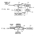
- Fig. 2B is a schematic drawing of an operation of a waveform measurement apparatus shown in Fig. 2A. Assume that the measured light carries an optical pulse signal with a repetition frequency f 0 .
- An optical sampling gate 511 comprises a nonlinear optical medium, and generates an intensity correlation optical signal of the measured light and the optical sampling pulse.
- the intensity correlation optical signal refers to an optical signal generated by the measured light and the optical sampling pulse being overlapped in a time domain.
- a sampling frequency signal generator 512 extracts a clock signal (frequency: f 0 ) from the measured light, and generates a sampling frequency signal (frequency: f 0 + ⁇ f) using the clock signal.
- a short pulse optical source 513 is driven by the sampling frequency signal. By so doing, an optical sampling pulse is generated. When both of the measured light and the optical sampling pulse are input to the optical sampling date 511, a nonlinear effect occurs. Then, an optical signal with intensity correlation of the measured light and the optical sampling pulse (i.e. the intensity correlation optical signal) is obtained.
- the intensity correlation optical signal output from the optical sampling gate 511 after being converted into an electrical signal by the optoelectronic converter 514, is input to a vertical axis signal port of the waveform display device 515.
- a frequency shift signal (frequency: ⁇ f) is input to a horizontal axis input port of the waveform display device 515.
- the waveform display device 515 can display the waveform of the measured light.
- the frequency ⁇ f is substantially low, compared with the frequency f 0 . Therefore, the issue of the band limitation should be solved.
- the nonlinear effect which occurs in the nonlinear optical medium of the optical sampling gate 511, depends on polarization states of the incident measured light and optical sampling pulse. Consequently, accurate observation of the waveform of an optical signal with an arbitrary polarization state is difficult by the optical waveform measurement apparatus shown in Fig. 2A.
- Non-patent Document 1 describes an optical waveform measurement apparatus, which solves the above issue of the polarization dependency.
- the apparatus described in Non-patent Document 1 employs a polarization diversity scheme as shown in Fig. 3. That is, an optical signal is separated into a TE polarization component and a TM polarization component by using a polarization beam splitter (PBS) 521.
- PBS polarization beam splitter
- the TE polarization component and the TM polarization component are input to KTP crystals 522 and 523, respectively, which are provided as a nonlinear optical medium.
- a pair of the optical signals output from the KTP crystals 522 and 523 is guided to a photo detector element 524.
- the apparatus comprises transmitters 530 and 531, an optical source 532 for generating an optical sampling pulse, a mode locked fiber laser (MLFL) 533 for generating the measured light, half wave plates (HWP) 534 and 535, mirrors 536-538, an A/D converter 539, and a computer 540 .
- MLFL mode locked fiber laser
- HWP half wave plates
- Non-patent document 2 describes another optical waveform measurement apparatus, which also solves the above issue of the polarization dependency.
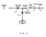
- the apparatus described in Non-patent document 2 comprises polarization controllers for controlling each of the polarization states of the measured light and the optical sampling pulse, as shown in Fig. 4. That is, a polarization controller 541 controls the polarization state of the measured light, and a polarization controller 542 controls the polarization state of the optical sampling pulse.
- a directional coupler 543 combines the measured light and the optical sampling pulse, each having controlled polarization states, and guides them to an optical fiber 544.
- the optical fiber 544 is a nonlinear optical medium, and causes a nonlinear effect.
- a polarizer 545 extracts a prescribed polarization component from the optical output of the optical fiber 544.
- a wavelength filter 546 extracts a wavelength component of the measured light.
- the polarization direction of the measured light is controlled so as to be orthogonal to the polarization main axis of the polarizer 545.
- the polarization direction of the optical sampling pulse is controlled so that the polarization direction of the optical sampling pulse differs from that of the measured light by 40°-50° (preferably 45°).
- the optical pulse of the measured light overlaps the optical sampling pulse in a time domain, the optical pulse of the measured light is output via the polarizer 545, and if the optical pulse of the measured light does not overlap the optical sampling pulse in the time domain, the optical pulse of the measured light is blocked by the polarizer 545.
- Patent Documents 1 and 2 are known as technologies relating to the above optical waveform measurement.
- Patent Document 1 Japanese Patent Application Publication No. 7-98464
- Patent Document 2 Japanese Patent No. 3494661
- Non-Patent Document 1 N.Yamada et al., "Polarization-insensitive optical sampling system using two KTP crystals," IEEE Photonics technology letters, vol. 16, No. 1, pp. 215-217, 2004
- Non-Patent Document 2 S.
- Non-Patent Document 1 requires two costly KTP crystals as the nonlinear optical medium. For that reason, cost reduction of the optical waveform measurement apparatus is difficult to achieve.
- Non-Patent Document 2 requires setting of the polarization states of the measured light and the optical sampling pulse before operating the optical waveform measurement apparatus. For that reason, if polarization change occurs in the optical fiber during the operation, accurate measurement of the optical waveform is difficult afterwards.
- An optical waveform measurement apparatus comprises a first polarization controller for controlling a polarization state of measured light, a second polarization controller for controlling a polarization state of an optical sampling pulse for sampling the measured light, a nonlinear optical medium, to which the measured light having the polarization state controlled by the first polarization controller and the optical sampling pulse having the polarization state controlled by the second polarization controller are input, an extraction unit for extracting a prescribed linear polarization component from an optical signal output from the nonlinear optical medium, a first adjustment unit for adjusting the first polarization controller, based on an optical signal output from the nonlinear optical medium, so that a polarization direction of the measured light has a first angle with respect to a polarization component extraction axis of the extraction unit, and a second adjustment unit for adjusting the second polarization controller, based on at least one of an optical signal output from the nonlinear optical medium and an optical signal output from the extraction unit, so that a polarization direction of the optical sampling pulse
- the first and second polarization controllers are adjusted based on the measured light and the optical sampling pulse actually used during the operation of the optical waveform measurement apparatus. Therefore, the polarization states of the measured light and the optical sampling pulse can be appropriately controlled at all time even during the operation of the optical waveform measurement apparatus.
- the polarization states of the measured light and the optical sampling pulse are appropriately controlled even during the operation of the optical waveform measurement apparatus, it is possible to measure or observe the waveform of the optical signal precisely.
- Fig. 5 is a diagram showing a fundamental configuration of the optical waveform measurement apparatus of the present invention.
- the optical waveform measurement apparatus of the present invention observes or measures the waveform of an optical signal carried by measured light, and specifically, the apparatus comprises a function for displaying the shape of the optical waveform by optical sampling.
- the optical waveform measurement apparatus of the present invention also comprises an optical sampling circuit 1 and a display unit 11.
- a first polarization controller 2 controls a polarization state of the measured light in accordance with an instruction from a first adjustment unit 6.
- a second polarization controller 3 controls a polarization state of an optical sampling pulse for sampling the measured light in accordance with an instruction from a second adjustment unit 7.
- the measured light, the polarization state of which is controlled by the first polarization controller 2, and the optical sampling pulse, the polarization state of which is controlled by the second polarization controller 3 are input to a nonlinear optical medium 4.
- the polarization state of the measured light is changed by a nonlinear effect in the nonlinear optical medium 4. Note that the nonlinear effect is caused by the optical sampling pulse.
- An extraction unit 5 can be a polarizer, for example, and extracts a prescribed linear polarization component from an optical signal output from the nonlinear optical medium 4.
- the first adjustment unit 6 adjusts the first polarization controller 1 so that the polarization direction of the measured light has a first angle with respect to a polarization component extraction axis of the extraction unit 5, based on the optical signal output from the nonlinear optical medium 4.
- the second adjustment unit 7 adjusts the second polarization controller 2 so that the polarization direction of the optical sampling pulse has a second angle with respect to the polarization component extraction axis of the extraction unit 5, based on the optical signal output from the nonlinear optical medium 4 and the optical signal output from the extraction unit 5.
- the first adjustment unit 6 and the second adjustment unit 7 can operate independently from each other.
- the second adjustment unit 7 may adjust the second polarization controller 2 based on either one of the optical signal output from the nonlinear optical medium 4 or the optical signal output from the extraction unit 5.
- the display unit 11 can be an oscilloscope, and displays the waveform of the optical signal carried by the measured light by using the optical signal extracted by the extraction unit 5.
- Figs. 6A-6C are diagrams explaining the operation of an optical sampling circuit 1.
- the polarization direction of the input optical signal (the measured light) is controlled so as to be approximately orthogonal to the polarization component extraction axis of the extraction unit 5, as shown in Fig. 6A.
- the extraction unit 5 is a polarizer
- the polarization component extraction axis is equivalent to a polarization main axis of the polarizer.
- the polarization state of the optical signal does not change in the nonlinear optical medium 4, as show in Fig. 6B. That is, in such a case, the polarization direction of the optical signal output from the nonlinear optical medium 4 is orthogonal to the polarization component extraction axis of the extraction unit 5. Therefore, in this case, the optical signal is blocked by the extraction unit 5.
- the polarization direction of the optical sampling pulse is, as shown in Figs. 6B and 6C, controlled in a direction of 40°-50° (preferably 45°) with respect to the polarization component extraction axis of the extraction unit 5.
- the polarization direction of the optical sampling pulse is controlled so that the polarization direction of the optical signal and the polarization direction of the optical sampling pulse are different from each other by 40°-50° (preferably 45°) .
- the polarization state of the optical signal changes under the influence of the optical sampling pulse in the nonlinear optical medium 4.
- the peak power of the optical sampling pulse is sufficiently larger than the power of the optical signal.
- the optical signal is parametrically amplified by the optical sampling pulse due to the nonlinear effect in the nonlinear optical medium 4, and additionally, the polarization direction of the optical signal approximately matches the polarization direction of the optical sampling pulse.
- the optical signal amplified by the optical sampling pulse in the nonlinear optical medium 4 contains a relatively large polarization component in a direction of the polarization component extraction axis of the extraction unit 5.
- the polarization direction of the measured light is controlled to be approximately orthogonal to the polarization component extraction axis of the extraction unit 5, the polarization direction of the optical sampling pulse is controlled in a direction of 40°-50° (preferably 45°) with respect to the polarization component extraction axis of the extraction unit 5.
- the polarization direction of the optical sampling pulse is controlled so that the polarization direction of the measured light and the polarization direction of the optical sampling pulse are different from each other by 40°-50° (preferably 45°).
- the first adjustment unit 6 and the second adjustment unit 7 constantly adjust the states of the polarization controllers 2 and 3 in parallel with the operation for measuring the waveform of the measured light.
- Fig. 7 is a diagram showing a configuration of the optical sampling circuit used in the optical waveform measurement apparatus of the embodiments of the present invention. It should be noted that the optical sampling circuit is not only for the use in the optical waveform measurement apparatus, but it is applicable to other usage.
- the optical sampling circuit can operate as an optical switch for extracting the M optical pulses from the N optical pulses (M ⁇ N).
- the first polarization controller 2 (hereinafter simply referred to as "polarization controller 2") controls the polarization state of the measured light.
- the measure light carries an optical signal, the waveform of which is to be observed.
- the optical signal is an optical pulse signal with a repetition frequency f 0 , for example.
- the repetition frequency f 0 is not limited in particular; however, it is assumed to be a several ten Gb/s, for example.
- the wavelength of the measured light is assumed to be ⁇ s .
- a sampling pulse optical source 21 generates an optical sampling pulse for sampling of the measured light.
- the repetition frequency of the optical sampling pulse is "f 0 /N + ⁇ f", for example.
- N is an integer including 1
- ⁇ f is a frequency substantially smaller than f 0 .
- the wavelength of the light carrying the optical sampling pulse is ⁇ c .
- the second polarization controller 3 (hereinafter simply referred to as "polarization controller 3") controls the polarization state of the optical sampling pulse.
- the polarization controllers 2 and 3 are wave plate polarization controllers in the present embodiment.
- the wave plate polarization controller comprises ⁇ /4 wave plate and ⁇ /2 wave plate, and controls the polarization state of the incident light by individually rotating those wave plates.
- An optical coupler 22 combines the measured light having the polarization state controlled by the polarization controller 2 and the optical sampling pulse having the polarization state controlled by the polarization controller 3, and guides them to an optical fiber 23.
- the optical fiber 23 is an embodiment of the nonlinear optical medium 4 shown in Fig. 5, and it is preferable to use a highly nonlinear optical fiber, for example.
- the polarization state of the measured light is changed by the nonlinear effect caused by the optical sampling pulse.
- the measured light is parametrically amplified by the optical sampling pulse.
- the optical signal output from the optical fiber 23 (including the measured light and the optical sampling pulse) is directed to a polarizer 24 by free space transmission.
- the polarizer 24, corresponding to the extraction unit 5 shown in Fig. 5, extracts a prescribed linear polarization component. Note that the operation of the polarizer 24 is the same as explained with reference to Figs. 6A-6C.
- the transmissive wavelength of the bandpass filter 25 is ⁇ s . In other words, the bandpass filter 25 extracts and outputs the measured light, while removing the optical sampling pulse.
- the optical signal output from the optical fiber 23 is split by optical splitters 26 and 27, and the split signals are guided to a polarizer 31 and a bandpass filter 41.
- a polarization main axis (polarization component extraction axis) of the polarizer 31 is set in a direction rotated clockwise by 45° from the polarization main axis (polarization component extraction axis) of the polarizer 24, as shown in Fig. 8.
- the polarization direction of the optical sampling pulse is, as explained with reference to Figs. 6A-6C, controlled in a direction rotated counterclockwise by approximately 45° from the polarization main axis of the polarizer 24.
- the polarization direction of the optical sampling pulse is controlled so as to be orthogonal to the polarization main axis of the polarizer 31 by setting the polarization main axis of the polarizer 31 as described above.
- the transmissive wavelength of the bandpass filter 32 is ⁇ c . That is, the bandpass filter 32 extracts the wavelength component of the optical sampling pulse from the optical output of the polarizer 31.
- the bandpass filter 32 may be provided to the input side of the polarizer 31 instead of being provided in the output side of the polarizer 31.
- a photo detector 33 is for example a photodiode, and detects the power of the optical signal passing through the bandpass filter 32. In other words, the photo detector 33 detects the power of the optical sampling pulse extracted by the polarizer 31.
- a control unit 34 generates a control signal for adjusting the state of the polarization controller 3 based on the optical power detected by the photo detector 33. Note that details of the operation of the control unit 34 are provided later.
- a driver 35 controls the state of the polarization controller 3 in accordance with the control signal generated by the control unit 34. As described above, the state of the polarization controller 3 is controlled by feedback control using the optical signal output from the optical fiber 23.
- the transmissive wavelength of a bandpass filter 41 is ⁇ s . That is, the bandpass filter 41 extracts the wavelength component of the measured light from the optical signal output from the optical fiber 23.
- a photo detector 42 is for example a photodiode, and detects the optical power of the optical signal passing through the bandpass filter 41. In other words, the photo detector 42 detects the power of the measured light output from the optical fiber 23.
- the optical signal output from the polarizer 24 is split by an optical splitter 43, and is guided to a bandpass filter 44.
- the transmissive wavelength of the bandpass filter 44 is ⁇ s . That is, the bandpass filter 44 extracts the wavelength component of the measured light from the optical signal output from the polarizer 24.
- a photo detector 45 is for example a photodiode, and extracts the power of the optical signal passing through the bandpass filter 44. In other words, the photo detector 45 detects the power of the measured light output from the polarizer 24.
- a control unit 46 generates a control signal for adjusting the state of the polarization controller 2 based on the optical power detected by the photo detector 42 and the optical power detected by the photo detector 45. Note that the details of the operation of the control unit 46 are provided later.
- a driver 47 controls the state of the polarization controller 2 in accordance with the control signal generated by the control unit 46. As described above, the state of the polarization controller 2 is controlled by feedback control using the optical signal output from the optical fiber 23 and the optical signal output from the polarizer 24.
- Fig. 9 is a flowchart showing the operation of the control unit 34 for controlling the polarization state of the optical sampling pulse.
- the process of the flowchart is executed constantly or periodically.
- the process of the flowchart can be executed in parallel with the operation for measuring the waveform of the measured light.
- the polarization direction of the optical sampling pulse is preferably controlled in a direction rotated by approximately 45° from the polarization main axis of the polarizer 24, as explained above.
- the polarization direction of the optical sampling pulse is orthogonal to the polarization main axis of the polarizer 31, and consequently, the optical sampling pulse is blocked by the polarizer 31.
- the control unit 34 adjusts the state of the polarization controller 3 so that the power of the optical sampling pulse detected by the photo detector 33 is minimized.
- step S1 the power of the optical sampling pulse output from the optical fiber 23 is detected, and the detected value is stored as "P(3)0". Additionally, the counter for counting a control variable is initialized. Note that in this flowchart, the power of the optical sampling pulse is detected by the photo detector 33.
- Steps S2-S9 are processes for adjusting the angle of the ⁇ /4 wave plate of the polarization controller 3. That is, in step S2, the ⁇ /4 wave plate of the polarization controller 3 is rotated in a prescribed direction (hereinafter the direction is assumed to be clockwise) by a given amount by providing a control signal to the driver 35.
- a given amount is not limited in particular; however, it is an amount of rotation, which slightly changes the polarization state of the measured light.
- step S3 the power of the optical sampling pulse is detected, and the detected value is stored as "P(3)1".
- step S4 "P(3)0” is compared with "P (3) 1". If “P(3)1 ⁇ P(3)0”, it is determined that the ⁇ /4 wave plate needs to be further rotated clockwise, and the process returns to step S2 after executing the process of step S5. In step S5, “P(3)1” obtained in step S3 is assigned to "P(3)0". By so doing, "P(3)1” obtained in step S3 is used as "P(3)0" in the next process routine. On the other hand, if “P(3)1 > P(3)0", it is determined that the ⁇ /4 wave plate needs to be rotated counterclockwise, and the process proceeds to step S6. In step S6, the ⁇ /4 wave plate is once restored to be the state before the execution of step S2, and the ⁇ /4 wave plate is rotated counterclockwise by a given amount. Afterwards, the process returns to step S3.
- step S7 the counter is incremented by 1 in step S7, and the value of the counter is checked in step S8.
- steps S11-S17 are basically the same as the processes in steps S2-S8 explained above. However, in steps S11-S17, the angle of the ⁇ /2 wave plate of the polarization controller 3 is adjusted. Note that steps S1-S17 may be repeated more than once.
- the power of the optical sampling pulse detected by the photo detector 33 is minimized.
- the polarization state of the optical sampling pulse is optimized.
- the control to minimize the power detected by the photo detector 33 is performed.
- a control to reduce the power to less than a prescribed threshold may be performed.
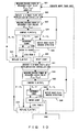
- Fig. 10 is a flowchart showing the operation of the control unit 46 for controlling the polarization state of the measured light. Processes in the flowchart are constantly or regularly repeated. The processes of the flowchart can be executed in parallel with the operation for measuring the waveform of the measured light. The processes of the flowchart shown in Fig. 9 and Fig. 10 can be executed independently from each other.
- steps S21-S29 and S31-S37 in the flowchart of Fig. 10 are basically the same as the processes of steps S1-S9 and S11-S17 .
- the processes of steps S21-S37 may be repeated more than once.
- the power of the measured light output from the optical fiber 23 and the power of the measured light output from the polarizer 24 are detected.
- power P (1) of the measured light input to the polarizer 24 and power P(2) of the measured light output from the polarizer 24 are detected.
- the state of the polarization controller 2 is adjusted so as to minimize a variable P represented by the following equation.
- k is a constant equivalent to optical loss generated due to the configuration of the optical sampling circuit 1.
- P P 2 / k - P 1
- step S21 power P (1) 0 of the measured light input to the polarizer 24 is detected by using the photo detector 42, and power P(2) 0 of the measured light output from the polarizer 24 is detected by using the photo detector 45.
- steps S23 and S32 power P (1) 1 of the measured light input to the polarizer 24 and power P (2) 1 of the measured light output from the polarizer 24 are detected.
- steps S24 and S33 the variable P0 is compared with the variable P1. Note that the variable P0 and the variable P1 can be obtained by the following equations.
- P ⁇ 0 P 2 0 / k - P 1 0
- P ⁇ 1 P 2 1 / k - P 1 1
- the variable P is minimized.
- the optical sampling pulse overlaps only a part of the optical pulse carried by the measured light in a time domain.
- "a part of the optical pulse” can be a case referring it as the M optical pulses in N optical pulses (M ⁇ N), or a case referring it as a part of each optical pulse.
- each of the optical power detected by the photo detector 42 and the photo detector 45 is assigned as "P(1)" and "P(2)", respectively.
- the power of the measured light output from the polarizer (PBS) 24 in the presence of the optical sampling pulse is "k ⁇ P s 1".
- k is a constant determined by the loss, which occurs when a prescribed polarization component is extracted in the polarizer 24 and the loss in the optical coupler for splitting the optical signal to the photo detector 45.
- the measured light in the absence of the optical sampling pulse, is completely blocked by the polarizer 24. Consequently, in such a case, the optical power P(2) detected by the photo detector 45 can be represented by the following equation.
- P 2 k ⁇ + P s ⁇ 1
- the optical power P(1) detected by the photo detector 42 when the polarization state of the measured light changes can be represented by the following equation (a).
- P 1 P s ⁇ 1 + ⁇ P ⁇ 1 + P s ⁇ 2
- the optical power leaking from the polarizer 24 due to the change in the polarization state of the measured light in the absence of the optical sampling pulse is assigned to be " ⁇ P".
- the optical sampling circuit used in the optical waveform measurement apparatus of the present embodiment comprises a function for optimizing the polarization states of each of the measured light and the optical sampling pulse.
- the adjustment operation by this function can be conducted in parallel to the operation for observing or measuring the waveform of the measured light. For that reason, even if the characteristics of the optical fiber 23 changes during the operation of the optical waveform measurement apparatus due to temperature change etc., for example, it is possible to maintain the polarization states of the measured light and the optical sampling pulse in the optical state at all time. Therefore, the optical waveform measurement apparatus of the embodiment can always measure the waveform of the optical signal precisely.
- the optical waveform measurement apparatus of the present embodiment does not require a costly configuration like the one described in Non-Patent Document 1.
- a highly nonlinear optical fiber to which germanium etc. is doped or a photonic crystal fiber etc., for example, can be used for the optical fiber 23.
- a photonic crystal fiber etc. can be used, for example.
- a wave-plate polarization controller having a ⁇ /2 wave plate and a ⁇ /4 wave plate is shown in the above embodiment; however, the polarization controller of the present invention is not limited to the above type.
- a variety of publicly known technologies can be employed as the polarization controllers 2 and 3.
- a LiNbO 3 polarization controller, a stress-type polarization controller, and a Faraday rotator etc. can be used for example.
- a stress-type polarization controller has fast response speed and is favorable for polarization controllers 2 and 3.
- An example of stress-type polarization controllers is, for example, "PolaRITE II" of General Photonics Corporation in the United States.
- Figs 12-16 are diagrams showing variation s of the optical sampling circuit.
- the optical sampling circuit shown in Fig. 12 comprises the bandpass filter 25 in the previous stage of the optical splitter 43.
- a part of the optical signal output from the bandpass filter 25 i.e. the measured light
- the optical splitter 43 is split by the optical splitter 43, and is guided to the photo detector 45.
- the number of the optical filters can be reduced compared with the configuration shown in Fig. 7.
- Each of the band eliminate filters 51-53 eliminates the wavelength component ⁇ c of the light carrying the optical sampling pulse; however, the filters do not eliminate the wavelength component ⁇ s of the measured light. Therefore, the band eliminate filters 51, 52, and 53 substantially operate similarly to the bandpass filters 25, 41, and 44, respectively. According to this configuration, the selection degree of freedom of the wavelength of the measured light is enhanced.
- the band eliminate filter can be realized by Fiber Bragg Gratings, for example.
- the optical sampling circuit shown in Fig. 14 comprises a band eliminate filter 51 in the previous stage of the optical splitter 43. A part of the optical signal output from the band eliminate filter 51 is split by the optical splitter 43 and is guided to the photo detector 45. According to this configuration, the number of the optical filters (specifically, the band eliminate filter 53) can be reduced compared with the configuration shown in Fig. 13.
- an optical path inputting an optical signal to the polarizer 24 and an optical path outputting the optical signal from the polarizer 24 are formed by an optical waveguide. Therefore the optical signal output from the optical fiber 23 is split by an optical coupler 61 and each split signal is guided to the polarizer 24 and an optical coupler 62.
- the optical coupler 62 splits the optical signal and each split signal is guided to the polarizer 31 and the band eliminate filter 52.
- the optical signal output from the polarizer 24 is split by the optical coupler 63 and each split signal is guided to the band eliminate filters 51 and 53. Introduction of this configuration improves the stability against the external vibration etc.
- the optical sampling circuit shown in Fig. 16 comprises the band eliminate filter 51 in the previous stage of the optical coupler 63. A part of the optical signal output from the band eliminate filter 51 is split by the optical coupler 63, and is guided to the photo detector 45. According to this configuration, the number of the optical filters (specifically the band eliminate filter 53) can be reduced compared with the configuration shown in Fig. 15.
- Fig. 17 is a diagram describing the configuration of an optical transmission system 70 using the optical switch relating to the present invention.
- a transmitter 71 performs time-division-multiplexing of N optical signals and transmits the multiplexed signals.
- the bit rate of each optical signal is assumed to be B/N (bps) .
- the bit rate of the multiplexed optical signal transmitted from the transmitter 71 is B (bps).
- the multiplexed signals are transmitted while being amplified by an optical amplifier provided in an optical transmission path.
- An optical distributor 72 distributes the multiplexed optical signals received via the optical transmission path into a plurality of optical switches 1-1 through 1-N.
- the optical distributor 72 is not limited in particular; however, it can be realized, for example, by a 1:N optical coupler.
- a clock recovery circuit 73 recovers a clock signal from the multiplexed optical signal.
- the frequency of the clock signal recovered by the clock recovery circuit 73 is B/N (Hz) .
- the recovered clock signal is provided to each of the optical switch 1-1 through 1-N.
- the timing of each clock signal being provided to the optical switch 1-1 through 1-N shifts 1/B seconds for each signal.
- the technique for recovering the clock signal from the input optical signal is known and is described, for example, in C. Boerner, et al., "320 Gbit/s Clock Recovery with Electro-Optical PLL using a bidirectionally operated Electroabsorption Modulator as Phase Comparator", OFC2005, Otu03 .
- Each of the optical switches 1-1 through 1-N is realized by the optical sampling circuit explained with reference to Figs. 7-16. However, when the optical sampling circuit explained with reference to Figs. 7-16 is used as each of the optical switches 1-1 through 1-N, the above multiplexed optical signal is input instead of the measured light. In addition, an optical clock signal synchronized with the clock signal generated by the clock recovery circuit 73 is used instead of the optical sampling pulse.
- Each of the optical signals output from the optical switches 1-1 through 1-N is received by receivers 74-1 through 74-N, respectively. By so doing, the N optical signals transmitted from the transmitter 71 are received by the receivers 74-1 through 74-N, respectively.
- the optical signal is separated by using the optical switch relating to the present invention.
- the polarization state of the multiplexed optical signal and that of the optical clock signal are appropriately controlled at all time in the optical switch relating to the present invention. Consequently, the communication quality can be improved.
- the optical waveform measurement apparatus of the embodiment of the present invention is an optical sampling oscilloscope, and displays the waveform of the measured light sampled by the optical sampling circuit explained with reference to Figs. 7-16.
- Figs. 7-16 In the following description, brief explanation of the operation principle of the optical sampling oscilloscope is provided with reference to Fig. 18.
- the frequency of the optical sampling pulse to be prepared is "f 0 /N + ⁇ f".
- N is an integer of 1 or larger, and it is “2” in the example of Fig. 18.
- ⁇ f is a frequency substantially lower than "f 0 ".
- the measured light and the optical sampling pulse are input to the nonlinear optical medium of the optical sampling circuit explained above (the optical fiber 23 in the above embodiment).
- the pulse width of the optical sampling pulse is preferably narrower than the pulse width of the optical signal to be observed.
- the frequency of the optical sampling pulse to be prepared may be "f 0 /N - ⁇ f".
- the optical sampling circuit performs sampling of the measured light in a time domain where the optical sampling pulse is present and outputs the sample.
- the optical signal output from the optical sampling circuit is converted into an electrical signal by the photo detector circuit.
- the electrical signal represents the power of the optical signal.
- optical power values S1-S4 are obtained respectively corresponding to the optical sampling pulses SP1-SP4.
- the frequency of the optical sampling pulse is slightly shifted from the frequency of the optical signal carried by the measured light (or 1/N of the frequency) .
- the time change of the power of the optical signal can be detected.
- the optical power values S1-S4 obtained in the above manner are displayed in a display device. By so doing, the waveform of the optical signal is displayed.
- the evaluation of the quality of an optical waveform based on the waveform of the optical signal is publicly known technique, and various types of evaluation software are known widely.
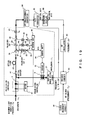
- Fig. 19 is a diagram showing a detailed configuration of the optical waveform measurement apparatus of the embodiment.
- the optical waveform measurement apparatus comprises the above optical sampling circuit. Note that this drawing shows the configuration of the optical sampling circuit 1 shown in Fig. 7; however, any of the above other optical sampling circuit can be used.
- a clock recovery circuit 81 recovers a clock signal from the measured light.
- the frequency of the recovered clock signal is "f 0 ".
- An RF oscillator 82 generates an RF signal having a frequency ⁇ f.
- a trigger circuit 83 generates a driving signal using the clock signal obtained by the clock recovery circuit 81 and the RF signal obtained by the RF oscillator 82.
- the sampling pulse optical source 21 generates the optical sampling pulse in accordance with the driving signal.
- the frequency of the driving signal is "f 0 /N + ⁇ f”. Consequently, the frequency of the generated optical sampling pulse is also "f 0 /N + ⁇ f".
- the measured light sampled by the optical sampling circuit 1 is converted into the electrical signal by an optoelectronic converter 84.
- the output signal of the optoelectronic converter 84 is converted into digital data by an A/D converter 85.
- the A/D converter 85 performs A/D conversion process in synchronization with the driving signal generated by the trigger circuit 83.
- the digital data obtained by the A/D converter 85 is provided to a waveform display device 86 as vertical axis data.
- the RF signal output from the RF oscillator 82 is provided to the waveform display device 86 as horizontal data.
- the waveform of the optical signal carried by the measured light is displayed in the waveform display device 86.
- an operation to optimize the polarization state of the measured light and that of the optical sampling pulse is executed at all time in parallel with the operation to display the waveform on the waveform display device 86. Therefore, the waveform of the measured light can be accurately measured at all time.
- Fig. 20 is a diagram showing the configuration of the waveform measurement apparatus being able to measure waveforms of a plurality of the measured lights. Note that the repetition frequency f 0 of the optical pulse carried by each of the measured lights is the same for each other.
- the optical waveform measurement apparatus comprises a plurality of polarization controllers 2-1 through 2-M and 3-1 through 3-M, a plurality of optical couplers 22-1 through 22-M, a plurality of optical fibers 23-1 through 23-M, a plurality of wavelength filters 25-1 through 25-M, a plurality of drivers 35-1 through 35-M and 47-1 through 47-M, a plurality of optoelectronic converters 84-1 through 84-M, a plurality of A/D converters 85-1 through 85-M, and a plurality of monitor circuits 91-1 through 91-M.
- sampling pulse optical source 21 the clock recovery circuit 81, the RF oscillator 82, and the waveform display device 86 are the same as described above.
- the directional coupler 92 directs the optical sampling pulse generated by the sampling pulse optical source 21 to the polarization controllers 3-1 through 3-M.
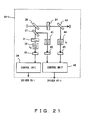
- Fig. 21 is a diagram showing a configuration of the monitor circuit.
- the monitor circuit 91-i comprises the polarizers 24 and 31, the optical splitters 26, 27, and 43, the bandpass filters 33, 41, and 44, the photo detectors 33, 42, and 45, and the control units 34 and 46.
- the optical signal output from the optical fiber 23-i is input to the monitor circuit 91-i.
- the bandpass filters 41 and 44 provided in the monitor circuit 91-i passes through the light having the wavelength ⁇ i .
- the control signals generated by the control units 34 and 46 provided in the monitor circuit 91-i are respectively sent to the drivers 35-i and 47-i.
- the optical waveform measurement apparatus shown in Fig. 20 is provided with a circuit for individually controlling the polarization states of each measured light.
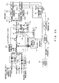
- Fig. 22 is a diagram showing another configuration of the optical waveform measurement apparatus being able to measure waveforms of a plurality of measured lights.
- the optical waveform measurement apparatus shown in Fig. 22 has a configuration in which the optical fibers 23-1 through 23-M and the monitor circuits 91-1 through 91-M of the optical waveform measurement apparatus shown in Fig. 20 are shared.
- the wavelengths of a plurality of the measured lights ( ⁇ 1- ⁇ M) are different from one another.
- a directional coupler 101 couples the output paths of the polarization controllers 2-1 through 2-M.
- An optical coupler 102 guides the optical signal output from the directional coupler 101 to the optical coupler 22, and splits a part of the optical signal to guide to a wavelength monitor unit 103.
- the wavelength monitor unit 103 detects the wavelength of the optical output of the directional coupler 101. Note that the wavelength detected by the wavelength monitor unit 103 is an arbitrary wavelength ( ⁇ 1- ⁇ M) of a plurality of the measured lights.
- Wavelength variable filters 104 and 105 are provided instead of the above bandpass filters 41 and 44, and can selectively pass arbitrary wavelengths ( ⁇ 1- ⁇ M).
- a directional coupler 106 guides the optical signal output from the polarizer 24 to the bandpass filters 25-1 through 25-M.
- the center wavelengths of the bandpass filters 25-1 through 25-M are variable, respectively.
- the center wavelength of the bandpass filters 25-1 through 25-M is set by the wavelength monitor unit 103 when the wavelength monitor unit 103
- the wavelength variable filters 104 and 105 upon reception of this notification, individually set the transmissive wavelength at " ⁇ i " .
- the power of the optical signal output from the wavelength variable filters 104 and 105 is detected by the photo detectors 42 and 45.
- the control unit 46 executes the process in the flowchart shown in Fig. 10 by using the power value detected by the photo detectors 42 and 43. At that time, the control unit 46 controls the polarization state of the polarization controller 2-i via the driver 47-i.
- the above control can be realized by the following order, for example. That is, the control unit 46 generates a wavelength control signal designating the measured light, the polarization state of which is to be controlled.
- the wavelength control signal in this case is a signal cyclically designating the wavelength ⁇ 1- ⁇ M one by one.
- the wavelength control signal is sent to the wavelength monitor unit 103.
- the wavelength monitor unit 103 monitors the optical power of the designated wavelength, and, if the power is larger than a threshold, determines that the corresponding measured light is input. Afterwards, the determination is notified to the wavelength variable filters 104 and 105.
- the operations following to the above operations are the same as the described above. Introduction of this sequence allows the sequential optimization of the polarization state of a plurality of the measured lights while continuing the waveform measurement operations.
Landscapes
- Physics & Mathematics (AREA)
- Spectroscopy & Molecular Physics (AREA)
- General Physics & Mathematics (AREA)
- Electromagnetism (AREA)
- Engineering & Computer Science (AREA)
- Computer Networks & Wireless Communication (AREA)
- Signal Processing (AREA)
- Photometry And Measurement Of Optical Pulse Characteristics (AREA)
- Optical Modulation, Optical Deflection, Nonlinear Optics, Optical Demodulation, Optical Logic Elements (AREA)
Abstract
Description
- The present invention relates to an optical waveform measurement apparatus and an optical waveform measurement method, and particularly relates to an optical waveform measurement apparatus and an optical waveform measurement method for measuring waveform of an optical signal with a high bit rate.
- A function to observe optical pulse waveforms is necessary for evaluating the quality of the optical signal in receivers of optical communication systems, and it can be applied for the purpose of monitoring the signal quality in optical nodes or optical repeaters in optical communication systems. Meanwhile, along with increase in the capacity for optical fiber communications, the bit rate of the optical signal has reached 40 Gb/s. In addition, as the next generation technology, the research and development of a system transmitting an optical signal at 160 Gb/s or higher is in progress. In order to support such research and development, an optical waveform measurement apparatus and an optical waveform measurement method allowing highly precise observation of the waveform of an optical signal are required. It should be noted that the function to measure or to observe optical pulse waveforms could be used for evaluating a variety of optical components.
- The conventional optical waveform measurement apparatus converts a measured optical signal (optical pulse) into an electrical signal using an
optoelectronic converter 501, as in an example of Fig. 1. A samplingpulse generation circuit 503 generates a sampling pulse in accordance with a trigger signal generated by atrigger circuit 502. At that time, the sampling pulse is not an optical signal but an electrical signal. Asampling circuit 504 conducts sampling of the electrical signal output from theoptoelectronic converter 501 with the sampling pulse. Awaveform display device 505 displays the sampling result. In other words, the waveform of an optical signal is observed after the optical signal is converted into an electrical signal. - At that time, in order to observe the waveform of the optical signal with high accuracy, all frequency components constituting the optical signal have to be received. For that reason, the waveform measurement apparatus needs to have a band sufficiently wider than the band corresponding to the bit rate of the optical signal. Here, the band observed by the waveform measurement apparatus shown in Fig. 1 is limited by a device having a narrowest band among the optoelectronic converter, the trigger circuit, the sampling circuit and the waveform display device. However, since the operation band of an electrical circuit is around 50 GHz, highly accurate observation of the optical signal with 40 Gb/s by a waveform measurement apparatus shown in Fig. 1 is considered to be difficult.
- For a technology to solve the issue of band limitation, an optical sampling technique, which conducts sampling of optical signals without modification, is known widely. In the following, the optical sampling technique is explained with reference to Fig. 2A and Fig. 2B. Note that Fig. 2B is a schematic drawing of an operation of a waveform measurement apparatus shown in Fig. 2A. Assume that the measured light carries an optical pulse signal with a repetition frequency f0.
- An
optical sampling gate 511 comprises a nonlinear optical medium, and generates an intensity correlation optical signal of the measured light and the optical sampling pulse. In this description, the intensity correlation optical signal refers to an optical signal generated by the measured light and the optical sampling pulse being overlapped in a time domain. - A sampling
frequency signal generator 512 extracts a clock signal (frequency: f0) from the measured light, and generates a sampling frequency signal (frequency: f0+Δf) using the clock signal. A short pulseoptical source 513 is driven by the sampling frequency signal. By so doing, an optical sampling pulse is generated. When both of the measured light and the optical sampling pulse are input to theoptical sampling date 511, a nonlinear effect occurs. Then, an optical signal with intensity correlation of the measured light and the optical sampling pulse (i.e. the intensity correlation optical signal) is obtained. - The intensity correlation optical signal output from the
optical sampling gate 511, after being converted into an electrical signal by theoptoelectronic converter 514, is input to a vertical axis signal port of thewaveform display device 515. To a horizontal axis input port of thewaveform display device 515, a frequency shift signal (frequency: Δf) is input. By so doing, thewaveform display device 515 can display the waveform of the measured light. Here, the frequency Δf is substantially low, compared with the frequency f0. Therefore, the issue of the band limitation should be solved. - However, the nonlinear effect, which occurs in the nonlinear optical medium of the
optical sampling gate 511, depends on polarization states of the incident measured light and optical sampling pulse. Consequently, accurate observation of the waveform of an optical signal with an arbitrary polarization state is difficult by the optical waveform measurement apparatus shown in Fig. 2A. - Non-patent
Document 1 describes an optical waveform measurement apparatus, which solves the above issue of the polarization dependency. The apparatus described inNon-patent Document 1 employs a polarization diversity scheme as shown in Fig. 3. That is, an optical signal is separated into a TE polarization component and a TM polarization component by using a polarization beam splitter (PBS) 521. The TE polarization component and the TM polarization component are input toKTP crystals KTP crystals photo detector element 524. Note that the apparatus comprisestransmitters optical source 532 for generating an optical sampling pulse, a mode locked fiber laser (MLFL) 533 for generating the measured light, half wave plates (HWP) 534 and 535, mirrors 536-538, an A/D converter 539, and acomputer 540 . - Non-patent
document 2 describes another optical waveform measurement apparatus, which also solves the above issue of the polarization dependency. The apparatus described inNon-patent document 2 comprises polarization controllers for controlling each of the polarization states of the measured light and the optical sampling pulse, as shown in Fig. 4. That is, apolarization controller 541 controls the polarization state of the measured light, and apolarization controller 542 controls the polarization state of the optical sampling pulse. Adirectional coupler 543 combines the measured light and the optical sampling pulse, each having controlled polarization states, and guides them to anoptical fiber 544. Theoptical fiber 544 is a nonlinear optical medium, and causes a nonlinear effect. Apolarizer 545 extracts a prescribed polarization component from the optical output of theoptical fiber 544. Awavelength filter 546 extracts a wavelength component of the measured light. - The polarization direction of the measured light is controlled so as to be orthogonal to the polarization main axis of the
polarizer 545. The polarization direction of the optical sampling pulse is controlled so that the polarization direction of the optical sampling pulse differs from that of the measured light by 40°-50° (preferably 45°). In such a configuration, if the optical pulse of the measured light overlaps the optical sampling pulse in a time domain, the optical pulse of the measured light is output via thepolarizer 545, and if the optical pulse of the measured light does not overlap the optical sampling pulse in the time domain, the optical pulse of the measured light is blocked by thepolarizer 545. - It should be noted that
Patent Documents Document 3 are known as technologies relating to the above optical waveform measurement.
[Patent Document 1]
Japanese Patent Application Publication No. 7-98464
[Patent Document 2]
Japanese Patent No. 3494661
[Non-Patent Document 1]
N.Yamada et al., "Polarization-insensitive optical sampling system using two KTP crystals," IEEE Photonics technology letters, vol. 16, No. 1, pp. 215-217, 2004
[Non-Patent Document 2]
S. Watanabe et al., "novel Fiber Kerr-Switch with Parametric Gain: Demonstration of Optical Demultiplexing and Sampling up to 640 Gb/s," Postdeadline session, Th4.1.6, 30th European Conference on Optical Communication, September 5-9, 2004 Stockholm, Sweden
[Non-Patent Document 3]
S. Watanabe et al., "Ultrafast All-Optical 3R-Regeneration," IEICE Trans. Election, vol. E87-C, No. 7, July 2004 - The configuration described in
Non-Patent Document 1 requires two costly KTP crystals as the nonlinear optical medium. For that reason, cost reduction of the optical waveform measurement apparatus is difficult to achieve. - The configuration described in
Non-Patent Document 2 requires setting of the polarization states of the measured light and the optical sampling pulse before operating the optical waveform measurement apparatus. For that reason, if polarization change occurs in the optical fiber during the operation, accurate measurement of the optical waveform is difficult afterwards. - It is an object of the present invention to measure the waveform of a high-speed optical signal with high accuracy at all time in an optical waveform measurement apparatus having a relatively inexpensive configuration.
- An optical waveform measurement apparatus according to the present invention comprises a first polarization controller for controlling a polarization state of measured light, a second polarization controller for controlling a polarization state of an optical sampling pulse for sampling the measured light, a nonlinear optical medium, to which the measured light having the polarization state controlled by the first polarization controller and the optical sampling pulse having the polarization state controlled by the second polarization controller are input, an extraction unit for extracting a prescribed linear polarization component from an optical signal output from the nonlinear optical medium, a first adjustment unit for adjusting the first polarization controller, based on an optical signal output from the nonlinear optical medium, so that a polarization direction of the measured light has a first angle with respect to a polarization component extraction axis of the extraction unit, and a second adjustment unit for adjusting the second polarization controller, based on at least one of an optical signal output from the nonlinear optical medium and an optical signal output from the extraction unit, so that a polarization direction of the optical sampling pulse has a second angle with respect to a polarization component extraction axis of the extraction unit. An optical signal output from the extraction unit is used for waveform measurement of the measured light.
- In the above apparatus, the first and second polarization controllers are adjusted based on the measured light and the optical sampling pulse actually used during the operation of the optical waveform measurement apparatus. Therefore, the polarization states of the measured light and the optical sampling pulse can be appropriately controlled at all time even during the operation of the optical waveform measurement apparatus.
- According to the present invention, since the polarization states of the measured light and the optical sampling pulse are appropriately controlled even during the operation of the optical waveform measurement apparatus, it is possible to measure or observe the waveform of the optical signal precisely.
-
- Fig. 1 is a diagram showing a configuration of a first conventional optical waveform measurement apparatus;
- Figs. 2A and 2B are diagrams showing a configuration of a second conventional optical waveform measurement apparatus;
- Fig. 3 is a diagram showing a configuration of a third conventional optical waveform measurement apparatus;
- Fig. 4 is a diagram showing a configuration of a fourth conventional optical waveform measurement apparatus;
- Fig. 5 is a diagram showing a fundamental configuration of the optical waveform measurement apparatus of the present invention;
- Figs. 6A-6C are diagrams explaining an operation of the optical sampling circuit;
- Fig. 7 is a diagram showing a configuration of the optical sampling circuit used in the optical waveform measurement apparatus of the embodiments of the present invention;
- Fig. 8 is a diagram explaining the setting of the polarizer;
- Fig. 9 is a flowchart showing the operation of the control unit for controlling the polarization state of the optical sampling pulse;
- Fig. 10 is a flowchart showing the operation of the control unit for controlling the polarization state of the measured light;
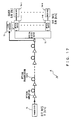
- Fig. 11 is a diagram explaining a major part of the method for controlling the polarization state of the measured light;
- Fig. 12 to Fig. 16 are variations of the optical sampling circuits;
- Fig. 17 is a diagram describing the configuration of an optical transmission system using the optical switch relating to the present invention;
- Fig. 18 is a diagram explaining a operation principle of the optical sampling oscilloscope;
- Fig. 19 is a diagram showing a detailed configuration of the optical waveform measurement apparatus of the embodiment;
- Fig. 20 is a diagram showing the configuration of the waveform measurement apparatus being able to measure waveforms of a plurality of the measured lights;
- Fig. 21 is a diagram showing a configuration of the monitor circuit; and
- Fig. 22 is a diagram showing another configuration of the optical waveform measurement apparatus being able to measure waveforms of a plurality of measured lights.
- Fig. 5 is a diagram showing a fundamental configuration of the optical waveform measurement apparatus of the present invention. The optical waveform measurement apparatus of the present invention observes or measures the waveform of an optical signal carried by measured light, and specifically, the apparatus comprises a function for displaying the shape of the optical waveform by optical sampling. The optical waveform measurement apparatus of the present invention also comprises an
optical sampling circuit 1 and adisplay unit 11. - A
first polarization controller 2 controls a polarization state of the measured light in accordance with an instruction from afirst adjustment unit 6. Asecond polarization controller 3 controls a polarization state of an optical sampling pulse for sampling the measured light in accordance with an instruction from a second adjustment unit 7. The measured light, the polarization state of which is controlled by thefirst polarization controller 2, and the optical sampling pulse, the polarization state of which is controlled by thesecond polarization controller 3, are input to a nonlinear optical medium 4. The polarization state of the measured light is changed by a nonlinear effect in the nonlinear optical medium 4. Note that the nonlinear effect is caused by the optical sampling pulse. Anextraction unit 5 can be a polarizer, for example, and extracts a prescribed linear polarization component from an optical signal output from the nonlinear optical medium 4. - The
first adjustment unit 6 adjusts thefirst polarization controller 1 so that the polarization direction of the measured light has a first angle with respect to a polarization component extraction axis of theextraction unit 5, based on the optical signal output from the nonlinear optical medium 4. The second adjustment unit 7 adjusts thesecond polarization controller 2 so that the polarization direction of the optical sampling pulse has a second angle with respect to the polarization component extraction axis of theextraction unit 5, based on the optical signal output from the nonlinear optical medium 4 and the optical signal output from theextraction unit 5. Here, thefirst adjustment unit 6 and the second adjustment unit 7 can operate independently from each other. The second adjustment unit 7 may adjust thesecond polarization controller 2 based on either one of the optical signal output from the nonlinear optical medium 4 or the optical signal output from theextraction unit 5. Thedisplay unit 11 can be an oscilloscope, and displays the waveform of the optical signal carried by the measured light by using the optical signal extracted by theextraction unit 5. - Figs. 6A-6C are diagrams explaining the operation of an
optical sampling circuit 1. In theoptical sampling circuit 1, the polarization direction of the input optical signal (the measured light) is controlled so as to be approximately orthogonal to the polarization component extraction axis of theextraction unit 5, as shown in Fig. 6A. Here, if theextraction unit 5 is a polarizer, the polarization component extraction axis is equivalent to a polarization main axis of the polarizer. - In a time domain where the optical sampling pulse is absent, the polarization state of the optical signal does not change in the nonlinear optical medium 4, as show in Fig. 6B. That is, in such a case, the polarization direction of the optical signal output from the nonlinear optical medium 4 is orthogonal to the polarization component extraction axis of the
extraction unit 5. Therefore, in this case, the optical signal is blocked by theextraction unit 5. - The polarization direction of the optical sampling pulse is, as shown in Figs. 6B and 6C, controlled in a direction of 40°-50° (preferably 45°) with respect to the polarization component extraction axis of the
extraction unit 5. In other words, the polarization direction of the optical sampling pulse is controlled so that the polarization direction of the optical signal and the polarization direction of the optical sampling pulse are different from each other by 40°-50° (preferably 45°) . - In a time domain where the optical sampling pulse is present, the polarization state of the optical signal changes under the influence of the optical sampling pulse in the nonlinear optical medium 4. Assume that the peak power of the optical sampling pulse is sufficiently larger than the power of the optical signal. Under the assumption, the optical signal is parametrically amplified by the optical sampling pulse due to the nonlinear effect in the nonlinear optical medium 4, and additionally, the polarization direction of the optical signal approximately matches the polarization direction of the optical sampling pulse. In other words, the optical signal amplified by the optical sampling pulse in the nonlinear optical medium 4 contains a relatively large polarization component in a direction of the polarization component extraction axis of the
extraction unit 5. Consequently, in the time domain where the optical sampling pulse is present, a part of polarization components of the amplified optical signal is extracted by theextraction unit 5. At that time, the optical wavelength of the light carrying the optical signal is not changed by the nonlinear effect. Note that the configuration and the operation of the above optical sampling circuit (optical switch) is also described, for example, inJapanese Patent Application No. 2005-200572 US Serial Number is 11/216,213 - In order to realize the optical sampling shown in Fig. 6C, the polarization direction of the measured light is controlled to be approximately orthogonal to the polarization component extraction axis of the
extraction unit 5, the polarization direction of the optical sampling pulse is controlled in a direction of 40°-50° (preferably 45°) with respect to the polarization component extraction axis of theextraction unit 5. Alternatively, the polarization direction of the optical sampling pulse is controlled so that the polarization direction of the measured light and the polarization direction of the optical sampling pulse are different from each other by 40°-50° (preferably 45°). In the embodiments of the present invention, thefirst adjustment unit 6 and the second adjustment unit 7 constantly adjust the states of thepolarization controllers - Fig. 7 is a diagram showing a configuration of the optical sampling circuit used in the optical waveform measurement apparatus of the embodiments of the present invention. It should be noted that the optical sampling circuit is not only for the use in the optical waveform measurement apparatus, but it is applicable to other usage. The optical sampling circuit can operate as an optical switch for extracting the M optical pulses from the N optical pulses (M<N).
- The first polarization controller 2 (hereinafter simply referred to as "
polarization controller 2") controls the polarization state of the measured light. In this case, the measure light carries an optical signal, the waveform of which is to be observed. The optical signal is an optical pulse signal with a repetition frequency f0, for example. The repetition frequency f0 is not limited in particular; however, it is assumed to be a several ten Gb/s, for example. The wavelength of the measured light is assumed to be λs. - A sampling pulse
optical source 21 generates an optical sampling pulse for sampling of the measured light. The repetition frequency of the optical sampling pulse is "f0/N + Δf", for example. "N" is an integer including 1, and "Δf" is a frequency substantially smaller than f0. The wavelength of the light carrying the optical sampling pulse is λc. - The second polarization controller 3 (hereinafter simply referred to as "
polarization controller 3") controls the polarization state of the optical sampling pulse. Note that thepolarization controllers - An
optical coupler 22 combines the measured light having the polarization state controlled by thepolarization controller 2 and the optical sampling pulse having the polarization state controlled by thepolarization controller 3, and guides them to anoptical fiber 23. Theoptical fiber 23 is an embodiment of the nonlinear optical medium 4 shown in Fig. 5, and it is preferable to use a highly nonlinear optical fiber, for example. In theoptical fiber 23, as explained with reference to Figs. 6A-6C, the polarization state of the measured light is changed by the nonlinear effect caused by the optical sampling pulse. The measured light is parametrically amplified by the optical sampling pulse. - The optical signal output from the optical fiber 23 (including the measured light and the optical sampling pulse) is directed to a
polarizer 24 by free space transmission. Thepolarizer 24, corresponding to theextraction unit 5 shown in Fig. 5, extracts a prescribed linear polarization component. Note that the operation of thepolarizer 24 is the same as explained with reference to Figs. 6A-6C. The transmissive wavelength of thebandpass filter 25 is λs. In other words, thebandpass filter 25 extracts and outputs the measured light, while removing the optical sampling pulse. - The optical signal output from the
optical fiber 23 is split byoptical splitters polarizer 31 and abandpass filter 41. A polarization main axis (polarization component extraction axis) of thepolarizer 31 is set in a direction rotated clockwise by 45° from the polarization main axis (polarization component extraction axis) of thepolarizer 24, as shown in Fig. 8. Here, the polarization direction of the optical sampling pulse is, as explained with reference to Figs. 6A-6C, controlled in a direction rotated counterclockwise by approximately 45° from the polarization main axis of thepolarizer 24. In other words, the polarization direction of the optical sampling pulse is controlled so as to be orthogonal to the polarization main axis of thepolarizer 31 by setting the polarization main axis of thepolarizer 31 as described above. - The transmissive wavelength of the
bandpass filter 32 is λc. That is, thebandpass filter 32 extracts the wavelength component of the optical sampling pulse from the optical output of thepolarizer 31. Note that thebandpass filter 32 may be provided to the input side of thepolarizer 31 instead of being provided in the output side of thepolarizer 31. Aphoto detector 33 is for example a photodiode, and detects the power of the optical signal passing through thebandpass filter 32. In other words, thephoto detector 33 detects the power of the optical sampling pulse extracted by thepolarizer 31. - A
control unit 34 generates a control signal for adjusting the state of thepolarization controller 3 based on the optical power detected by thephoto detector 33. Note that details of the operation of thecontrol unit 34 are provided later. Adriver 35 controls the state of thepolarization controller 3 in accordance with the control signal generated by thecontrol unit 34. As described above, the state of thepolarization controller 3 is controlled by feedback control using the optical signal output from theoptical fiber 23. - The transmissive wavelength of a
bandpass filter 41 is λs. That is, thebandpass filter 41 extracts the wavelength component of the measured light from the optical signal output from theoptical fiber 23. Aphoto detector 42 is for example a photodiode, and detects the optical power of the optical signal passing through thebandpass filter 41. In other words, thephoto detector 42 detects the power of the measured light output from theoptical fiber 23. - The optical signal output from the
polarizer 24 is split by anoptical splitter 43, and is guided to abandpass filter 44. The transmissive wavelength of thebandpass filter 44 is λs. That is, thebandpass filter 44 extracts the wavelength component of the measured light from the optical signal output from thepolarizer 24. Aphoto detector 45 is for example a photodiode, and extracts the power of the optical signal passing through thebandpass filter 44. In other words, thephoto detector 45 detects the power of the measured light output from thepolarizer 24. - A
control unit 46 generates a control signal for adjusting the state of thepolarization controller 2 based on the optical power detected by thephoto detector 42 and the optical power detected by thephoto detector 45. Note that the details of the operation of thecontrol unit 46 are provided later. Adriver 47 controls the state of thepolarization controller 2 in accordance with the control signal generated by thecontrol unit 46. As described above, the state of thepolarization controller 2 is controlled by feedback control using the optical signal output from theoptical fiber 23 and the optical signal output from thepolarizer 24. - Fig. 9 is a flowchart showing the operation of the
control unit 34 for controlling the polarization state of the optical sampling pulse. The process of the flowchart is executed constantly or periodically. In addition, the process of the flowchart can be executed in parallel with the operation for measuring the waveform of the measured light. - The polarization direction of the optical sampling pulse is preferably controlled in a direction rotated by approximately 45° from the polarization main axis of the
polarizer 24, as explained above. In this case, the polarization direction of the optical sampling pulse is orthogonal to the polarization main axis of thepolarizer 31, and consequently, the optical sampling pulse is blocked by thepolarizer 31. In other words, if the polarization direction of the optical sampling pulse is properly controlled, the power o the optical sampling pulse detected by thephoto detector 33 should be minimized. Thus, thecontrol unit 34 adjusts the state of thepolarization controller 3 so that the power of the optical sampling pulse detected by thephoto detector 33 is minimized. - In step S1, the power of the optical sampling pulse output from the
optical fiber 23 is detected, and the detected value is stored as "P(3)0". Additionally, the counter for counting a control variable is initialized. Note that in this flowchart, the power of the optical sampling pulse is detected by thephoto detector 33. - Steps S2-S9 are processes for adjusting the angle of the λ/4 wave plate of the
polarization controller 3. That is, in step S2, the λ/4 wave plate of thepolarization controller 3 is rotated in a prescribed direction (hereinafter the direction is assumed to be clockwise) by a given amount by providing a control signal to thedriver 35. Here, "a given amount" is not limited in particular; however, it is an amount of rotation, which slightly changes the polarization state of the measured light. In step S3, the power of the optical sampling pulse is detected, and the detected value is stored as "P(3)1". - In step S4, "P(3)0" is compared with "P (3) 1". If "P(3)1 < P(3)0", it is determined that the λ/4 wave plate needs to be further rotated clockwise, and the process returns to step S2 after executing the process of step S5. In step S5, "P(3)1" obtained in step S3 is assigned to "P(3)0". By so doing, "P(3)1" obtained in step S3 is used as "P(3)0" in the next process routine. On the other hand, if "P(3)1 > P(3)0", it is determined that the λ/4 wave plate needs to be rotated counterclockwise, and the process proceeds to step S6. In step S6, the λ/4 wave plate is once restored to be the state before the execution of step S2, and the λ/4 wave plate is rotated counterclockwise by a given amount. Afterwards, the process returns to step S3.
- If "P(3)0 = P(3)1", the counter is incremented by 1 in step S7, and the value of the counter is checked in step S8. In this case, "P (3) 0 = P (3) 1" includes a state where two values are approximately match (i.e. the difference in the two values is smaller than a prescribed threshold) in addition to a state where the two values matches completely. If the value of the counter is smaller than a specified value (5 in this example), the process returns to step S2 via step S5. On the other hand, the value of the counter has reached "5", the counter is reset in the step S9, and the process proceeds to step S11.
- Processes in steps S11-S17 are basically the same as the processes in steps S2-S8 explained above. However, in steps S11-S17, the angle of the λ/2 wave plate of the
polarization controller 3 is adjusted. Note that steps S1-S17 may be repeated more than once. - By executing steps S1-S17 as described above, the power of the optical sampling pulse detected by the
photo detector 33 is minimized. In other words, the polarization state of the optical sampling pulse is optimized. It should be noted that in the above embodiment, the control to minimize the power detected by thephoto detector 33 is performed. Alternatively, a control to reduce the power to less than a prescribed threshold may be performed. - Fig. 10 is a flowchart showing the operation of the
control unit 46 for controlling the polarization state of the measured light. Processes in the flowchart are constantly or regularly repeated. The processes of the flowchart can be executed in parallel with the operation for measuring the waveform of the measured light. The processes of the flowchart shown in Fig. 9 and Fig. 10 can be executed independently from each other. - Processes of steps S21-S29 and S31-S37 in the flowchart of Fig. 10 are basically the same as the processes of steps S1-S9 and S11-S17 . The processes of steps S21-S37 may be repeated more than once. However, in the flowchart shown in Fig. 10, the power of the measured light output from the
optical fiber 23 and the power of the measured light output from thepolarizer 24 are detected. In other words, power P (1) of the measured light input to thepolarizer 24 and power P(2) of the measured light output from thepolarizer 24 are detected. Then, the state of thepolarization controller 2 is adjusted so as to minimize a variable P represented by the following equation. Note that k is a constant equivalent to optical loss generated due to the configuration of theoptical sampling circuit 1.
- In order to realize the above control, in step S21, power P (1) 0 of the measured light input to the
polarizer 24 is detected by using thephoto detector 42, and power P(2) 0 of the measured light output from thepolarizer 24 is detected by using thephoto detector 45. In steps S23 and S32, power P (1) 1 of the measured light input to thepolarizer 24 and power P (2) 1 of the measured light output from thepolarizer 24 are detected. In addition, in steps S24 and S33, the variable P0 is compared with the variable P1. Note that the variable P0 and the variable P1 can be obtained by the following equations.

- By the above process, the variable P is minimized. In the following description, the reason that the polarization state of the measured light is optimized by minimizing the variable P is explained with reference to Fig. 11. Note that in the explanation of Fig. 11, the optical sampling pulse overlaps only a part of the optical pulse carried by the measured light in a time domain. Here, "a part of the optical pulse" can be a case referring it as the M optical pulses in N optical pulses (M<N), or a case referring it as a part of each optical pulse. In the model shown in Fig. 11, each of the optical power detected by the
photo detector 42 and thephoto detector 45 is assigned as "P(1)" and "P(2)", respectively. - Assume a state such that the polarization state of the measured light is optimized. Under such an optimized state, the average power of the measured light output from the
optical fiber 23 in the presence of the optical sampling pulse is assigned to be "P s1". The average power of the measured light output from theoptical fiber 23 in the absence of the optical sampling pulse is assigned to be "P s2". Then, the optical power P(1) detected by thephoto detector 42 can be represented by the following equation.
- In the above optimized state, the power of the measured light output from the polarizer (PBS) 24 in the presence of the optical sampling pulse is "k×
P s1". Here, k is a constant determined by the loss, which occurs when a prescribed polarization component is extracted in thepolarizer 24 and the loss in the optical coupler for splitting the optical signal to thephoto detector 45. On the other hand, the measured light, in the absence of the optical sampling pulse, is completely blocked by thepolarizer 24. Consequently, in such a case, the optical power P(2) detected by thephoto detector 45 can be represented by the following equation.
- Suppose the polarization state of the measured light is changed. In this case, the difference between the polarization direction of the measured light and that of the optical sampling pulse deviates from the optimal value, causing the change in the nonlinear effect (particularly, the gain of the optical parametric amplification) caused in the
optical fiber 23. Here, the amount of change in the power of the measured light due to the change in the polarization state of the measured light in the presence of the optical sampling pulse is assigned to be "ΔP1". Then, the optical power P(1) detected by thephoto detector 42 when the polarization state of the measured light changes can be represented by the following equation (a).
- When the polarization state of the measured light changes, the polarization direction of the measured light in the absence of the optical sampling pulse deviates from the direction orthogonal to the polarization main axis of the
polarizer 24. For that reason, a part of the measured light leaks from thepolarizer 24. Here, the optical power leaking from thepolarizer 24 due to the change in the polarization state of the measured light in the absence of the optical sampling pulse is assigned to be "ΔP". Then, the optical power P (2) detected by thephoto detector 45 when the polarization state of the measured light changes can be represented by the following equation (b).
- From the equation (a) and the equation (b), the following equation (c) can be obtained.

- As the polarization state of the measured light becomes closer to the optimal state, "ΔP" should be smaller. Minimization of "ΔP" is equivalent to the minimization of "P(2)/k - P(1)" in the above equation (c). Consequently, by controlling to minimize "P(2)/k - P(1)" corresponding to the variable P, it is possible to optimize the polarization state of the measured light.
- As described above, the optical sampling circuit used in the optical waveform measurement apparatus of the present embodiment comprises a function for optimizing the polarization states of each of the measured light and the optical sampling pulse. The adjustment operation by this function can be conducted in parallel to the operation for observing or measuring the waveform of the measured light. For that reason, even if the characteristics of the
optical fiber 23 changes during the operation of the optical waveform measurement apparatus due to temperature change etc., for example, it is possible to maintain the polarization states of the measured light and the optical sampling pulse in the optical state at all time. Therefore, the optical waveform measurement apparatus of the embodiment can always measure the waveform of the optical signal precisely. In addition, the optical waveform measurement apparatus of the present embodiment does not require a costly configuration like the one described inNon-Patent Document 1. - A highly nonlinear optical fiber to which germanium etc. is doped or a photonic crystal fiber etc., for example, can be used for the
optical fiber 23. By using these optical fibers, stabilized characteristics even at the temperature change can be achieved. Instead of theoptical fiber 23, other nonlinear optical medium can be used. For the other nonlinear optical medium, a photonic crystal can be used, for example. - As the
polarization controllers polarization controllers polarization controllers - Figs 12-16 are diagrams showing variation s of the optical sampling circuit. The optical sampling circuit shown in Fig. 12 comprises the
bandpass filter 25 in the previous stage of theoptical splitter 43. A part of the optical signal output from the bandpass filter 25 (i.e. the measured light) is split by theoptical splitter 43, and is guided to thephoto detector 45. According to this configuration, the number of the optical filters (specifically, the bandpass filter 44) can be reduced compared with the configuration shown in Fig. 7. - The optical sampling circuit shown in Fig. 13, instead of the bandpass filters 25, 41, and 44 shown in Fig. 7, comprises band eliminate
filters filters - The optical sampling circuit shown in Fig. 14 comprises a band eliminate
filter 51 in the previous stage of theoptical splitter 43. A part of the optical signal output from the band eliminatefilter 51 is split by theoptical splitter 43 and is guided to thephoto detector 45. According to this configuration, the number of the optical filters (specifically, the band eliminate filter 53) can be reduced compared with the configuration shown in Fig. 13. - In the optical sampling circuit shown in Fig. 15, an optical path inputting an optical signal to the
polarizer 24 and an optical path outputting the optical signal from thepolarizer 24 are formed by an optical waveguide. Therefore the optical signal output from theoptical fiber 23 is split by anoptical coupler 61 and each split signal is guided to thepolarizer 24 and anoptical coupler 62. Theoptical coupler 62 splits the optical signal and each split signal is guided to thepolarizer 31 and the band eliminatefilter 52. The optical signal output from thepolarizer 24 is split by theoptical coupler 63 and each split signal is guided to the band eliminatefilters - The optical sampling circuit shown in Fig. 16 comprises the band eliminate
filter 51 in the previous stage of theoptical coupler 63. A part of the optical signal output from the band eliminatefilter 51 is split by theoptical coupler 63, and is guided to thephoto detector 45. According to this configuration, the number of the optical filters (specifically the band eliminate filter 53) can be reduced compared with the configuration shown in Fig. 15. - Fig. 17 is a diagram describing the configuration of an
optical transmission system 70 using the optical switch relating to the present invention. In Fig. 17, atransmitter 71 performs time-division-multiplexing of N optical signals and transmits the multiplexed signals. In this embodiment, the bit rate of each optical signal is assumed to be B/N (bps) . Then, the bit rate of the multiplexed optical signal transmitted from thetransmitter 71 is B (bps). The multiplexed signals are transmitted while being amplified by an optical amplifier provided in an optical transmission path. - An
optical distributor 72 distributes the multiplexed optical signals received via the optical transmission path into a plurality of optical switches 1-1 through 1-N. Theoptical distributor 72 is not limited in particular; however, it can be realized, for example, by a 1:N optical coupler. - A
clock recovery circuit 73 recovers a clock signal from the multiplexed optical signal. The frequency of the clock signal recovered by theclock recovery circuit 73 is B/N (Hz) . The recovered clock signal is provided to each of the optical switch 1-1 through 1-N. Here, the timing of each clock signal being provided to the optical switch 1-1 through 1-N shifts 1/B seconds for each signal. It should be noted that the technique for recovering the clock signal from the input optical signal is known and is described, for example, in C. Boerner, et al., "320 Gbit/s Clock Recovery with Electro-Optical PLL using a bidirectionally operated Electroabsorption Modulator as Phase Comparator", OFC2005, Otu03 . - Each of the optical switches 1-1 through 1-N is realized by the optical sampling circuit explained with reference to Figs. 7-16. However, when the optical sampling circuit explained with reference to Figs. 7-16 is used as each of the optical switches 1-1 through 1-N, the above multiplexed optical signal is input instead of the measured light. In addition, an optical clock signal synchronized with the clock signal generated by the
clock recovery circuit 73 is used instead of the optical sampling pulse. Each of the optical signals output from the optical switches 1-1 through 1-N is received by receivers 74-1 through 74-N, respectively. By so doing, the N optical signals transmitted from thetransmitter 71 are received by the receivers 74-1 through 74-N, respectively. - In the optical transmission system with the above configuration, the optical signal is separated by using the optical switch relating to the present invention. In this embodiment, the polarization state of the multiplexed optical signal and that of the optical clock signal are appropriately controlled at all time in the optical switch relating to the present invention. Consequently, the communication quality can be improved.
- The optical waveform measurement apparatus of the embodiment of the present invention is an optical sampling oscilloscope, and displays the waveform of the measured light sampled by the optical sampling circuit explained with reference to Figs. 7-16. In the following description, brief explanation of the operation principle of the optical sampling oscilloscope is provided with reference to Fig. 18.
- In the following description, it is assumed that the repetition frequency of the optical signal carried by the measured light is fo. In such a case, the frequency of the optical sampling pulse to be prepared is "f0/N + Δf". Here, "N" is an integer of 1 or larger, and it is "2" in the example of Fig. 18. "Δf" is a frequency substantially lower than "f0". The measured light and the optical sampling pulse are input to the nonlinear optical medium of the optical sampling circuit explained above (the
optical fiber 23 in the above embodiment). Note that the pulse width of the optical sampling pulse is preferably narrower than the pulse width of the optical signal to be observed. The frequency of the optical sampling pulse to be prepared may be "f0/N - Δf". - The optical sampling circuit performs sampling of the measured light in a time domain where the optical sampling pulse is present and outputs the sample. The optical signal output from the optical sampling circuit is converted into an electrical signal by the photo detector circuit. The electrical signal represents the power of the optical signal. In the example of Fig. 18, optical power values S1-S4 are obtained respectively corresponding to the optical sampling pulses SP1-SP4. Here, the frequency of the optical sampling pulse is slightly shifted from the frequency of the optical signal carried by the measured light (or 1/N of the frequency) . As a result, the time change of the power of the optical signal can be detected.
- The optical power values S1-S4 obtained in the above manner are displayed in a display device. By so doing, the waveform of the optical signal is displayed. Note that the evaluation of the quality of an optical waveform based on the waveform of the optical signal is publicly known technique, and various types of evaluation software are known widely.
- Fig. 19 is a diagram showing a detailed configuration of the optical waveform measurement apparatus of the embodiment. The optical waveform measurement apparatus comprises the above optical sampling circuit. Note that this drawing shows the configuration of the
optical sampling circuit 1 shown in Fig. 7; however, any of the above other optical sampling circuit can be used. - A
clock recovery circuit 81 recovers a clock signal from the measured light. The frequency of the recovered clock signal is "f0". AnRF oscillator 82 generates an RF signal having a frequency Δf. Atrigger circuit 83 generates a driving signal using the clock signal obtained by theclock recovery circuit 81 and the RF signal obtained by theRF oscillator 82. The sampling pulseoptical source 21 generates the optical sampling pulse in accordance with the driving signal. Here, the frequency of the driving signal is "f0/N + Δf". Consequently, the frequency of the generated optical sampling pulse is also "f0/N + Δf". - The measured light sampled by the
optical sampling circuit 1 is converted into the electrical signal by anoptoelectronic converter 84. The output signal of theoptoelectronic converter 84 is converted into digital data by an A/D converter 85. Here, the A/D converter 85 performs A/D conversion process in synchronization with the driving signal generated by thetrigger circuit 83. The digital data obtained by the A/D converter 85 is provided to awaveform display device 86 as vertical axis data. Meanwhile, the RF signal output from theRF oscillator 82 is provided to thewaveform display device 86 as horizontal data. - According to the above configuration, the waveform of the optical signal carried by the measured light is displayed in the
waveform display device 86. At that time, an operation to optimize the polarization state of the measured light and that of the optical sampling pulse is executed at all time in parallel with the operation to display the waveform on thewaveform display device 86. Therefore, the waveform of the measured light can be accurately measured at all time. - Fig. 20 is a diagram showing the configuration of the waveform measurement apparatus being able to measure waveforms of a plurality of the measured lights. Note that the repetition frequency f0 of the optical pulse carried by each of the measured lights is the same for each other.
- In order to measure the waveforms of a plurality of the measure lights, the optical waveform measurement apparatus comprises a plurality of polarization controllers 2-1 through 2-M and 3-1 through 3-M, a plurality of optical couplers 22-1 through 22-M, a plurality of optical fibers 23-1 through 23-M, a plurality of wavelength filters 25-1 through 25-M, a plurality of drivers 35-1 through 35-M and 47-1 through 47-M, a plurality of optoelectronic converters 84-1 through 84-M, a plurality of A/D converters 85-1 through 85-M, and a plurality of monitor circuits 91-1 through 91-M. Note that the sampling pulse
optical source 21, theclock recovery circuit 81, theRF oscillator 82, and thewaveform display device 86 are the same as described above. Thedirectional coupler 92 directs the optical sampling pulse generated by the sampling pulseoptical source 21 to the polarization controllers 3-1 through 3-M. - Fig. 21 is a diagram showing a configuration of the monitor circuit. In this drawing, the monitor circuits 91-i (i=l, 2, ...,M) represents an arbitrary one of a plurality of monitor circuits 91-1 through 91-M. The monitor circuit 91-i comprises the
polarizers optical splitters photo detectors control units control units - As described above, the optical waveform measurement apparatus shown in Fig. 20 is provided with a circuit for individually controlling the polarization states of each measured light.
- Fig. 22 is a diagram showing another configuration of the optical waveform measurement apparatus being able to measure waveforms of a plurality of measured lights. The optical waveform measurement apparatus shown in Fig. 22 has a configuration in which the optical fibers 23-1 through 23-M and the monitor circuits 91-1 through 91-M of the optical waveform measurement apparatus shown in Fig. 20 are shared. Here, the wavelengths of a plurality of the measured lights (λ1-λM) are different from one another.
- A
directional coupler 101 couples the output paths of the polarization controllers 2-1 through 2-M. Anoptical coupler 102 guides the optical signal output from thedirectional coupler 101 to theoptical coupler 22, and splits a part of the optical signal to guide to awavelength monitor unit 103. Thewavelength monitor unit 103 detects the wavelength of the optical output of thedirectional coupler 101. Note that the wavelength detected by thewavelength monitor unit 103 is an arbitrary wavelength (λ1-λM) of a plurality of the measured lights. Wavelengthvariable filters directional coupler 106 guides the optical signal output from thepolarizer 24 to the bandpass filters 25-1 through 25-M. The center wavelengths of the bandpass filters 25-1 through 25-M are variable, respectively. The center wavelength of the bandpass filters 25-1 through 25-M is set by thewavelength monitor unit 103 when thewavelength monitor unit 103 detects the wavelength λi. - When the measured optical pulse i (i=1, 2, ..., M) is input to the optical waveform measurement apparatus with the above configuration, the
wavelength monitor unit 103 notifies the wavelengthvariable filters variable filters variable filters photo detectors control unit 46 executes the process in the flowchart shown in Fig. 10 by using the power value detected by thephoto detectors control unit 46 controls the polarization state of the polarization controller 2-i via the driver 47-i. - The above control can be realized by the following order, for example. That is, the
control unit 46 generates a wavelength control signal designating the measured light, the polarization state of which is to be controlled. The wavelength control signal in this case is a signal cyclically designating the wavelength λ1-λM one by one. The wavelength control signal is sent to thewavelength monitor unit 103. Thewavelength monitor unit 103 monitors the optical power of the designated wavelength, and, if the power is larger than a threshold, determines that the corresponding measured light is input. Afterwards, the determination is notified to the wavelengthvariable filters
Claims (16)
- An optical waveform measurement apparatus, comprising:a first polarization controller (2) for controlling a polarization state of measured light;a second polarization controller (3) for controlling a polarization state of an optical sampling pulse for sampling the measured light;a nonlinear optical medium (4, 23), to which the measured light having the polarization state controlled by said first polarization controller and the optical sampling pulse having the polarization state controlled by said second polarization controller, are input;an extraction unit (5) for extracting a prescribed linear polarization component from an optical signal output from said nonlinear optical medium;a first adjustment unit (6, 46) for adjusting said first polarization controller, based on an optical signal output from said nonlinear optical medium, so that a polarization direction of the measured light has a first angle with respect to a polarization component extraction axis of said extraction unit; anda second adjustment unit (7, 34) for adjusting said second polarization controller, based on at least one of an optical signal output from said nonlinear optical medium and an optical signal output from said extraction unit, so that a polarization direction of the optical sampling pulse has a second angle with respect to a polarization component extraction axis of said extraction unit, whereinthe optical signal output from said extraction unit is used for waveform measurement of the measured light.
- The optical waveform measurement apparatus according to claim 1, wherein
said first adjustment unit adjusts said first polarization controller so that the polarization direction of the measured light is approximately orthogonal with respect to the polarization component extraction axis of said extraction unit, and
said second adjustment unit adjusts said second polarization controller so that the polarization direction of the measured light and the polarization direction of the optical sampling pulse are different from each other by 40-50 degrees. - The optical waveform measurement apparatus according to claim 1, wherein
said first adjustment unit adjusts said first polarization controller so that the polarization direction of the measured light is approximately orthogonal with respect to the polarization component extraction axis of said extraction unit;
and
said second adjustment unit adjusts said second polarization controller so that the polarization direction of the optical sampling pulse is rotated by 40-50 degrees from the polarization component extraction axis of said extraction unit. - The optical waveform measurement apparatus according to claim 3, wherein said second adjustment unit (7) comprises:a polarizer (31), which has a polarization component extraction axis in a direction of approximately 45 degrees with respect to the polarization component extraction axis of said extraction unit, for extracting the linear polarization component from the optical signal output from said nonlinear optical medium;an optical filter (32), provided at an input side or an output side of the polarizer, for transmitting a wavelength component of the optical sampling pulse; anda processing unit (34) for adjusting said second polarization controller so that power of the optical output from said optical filter is minimized.
- The optical waveform measurement apparatus according to claim 3, wherein said first adjustment unit (6) comprises:a first monitoring light generation unit (41) for generating first monitoring light by extracting a wavelength component of the measured light from an optical signal output from said nonlinear optical medium;a second monitoring light generation unit (44) for generating second monitoring light by extracting a wavelength component of the measured light from the optical signal output from said extraction unit; anda processing unit (46) for adjusting said first polarization controller based on power of the first and second monitoring light.
- The optical waveform measurement apparatus according to claim 5, wherein
said extraction unit comprises an optical filter extracting a wavelength component of the measured light, and
the second monitoring light is obtained by splitting the optical output of the optical filter. - The optical waveform measurement apparatus according to claim 3, wherein said first adjustment unit (6) comprises:a first monitoring light generation unit (52) for generating first monitoring light by eliminating a wavelength component of the optical sampling pulse from the optical signal output from said nonlinear optical medium;a second monitoring light generation unit (53) for generating second monitoring light by eliminating a wavelength component of the optical sampling pulse from an optical signal output from said extraction unit; anda processing unit (46) for adjusting said first polarization controller based on power of the first and second monitoring light.
- The optical waveform measurement apparatus according to claim 7, wherein
said extraction unit comprises an optical filter for eliminating the wavelength component of the optical sampling pulse, and
the second monitoring light is obtained by splitting the optical output of the optical filter. - The optical waveform measurement apparatus according to claim 5, wherein
said processing unit adjusts said first polarization controller so as to minimize "P2/k - P1" (where P1 represents power of the first monitoring light, P2 represents power of the second monitoring light, and k represents a prescribed constant). - The optical waveform measurement apparatus according to claim 1, wherein
an optical input path and an optical output path of said extraction unit are realized by free-space transmission. - The optical waveform measurement apparatus according to claim 1, wherein
an optical input path and an optical output path of said extraction unit are realized by an optical waveguide. - The optical waveform measurement apparatus according to claim 1, comprising:a sampling pulse optical source (21) for outputting an optical pulse having a sampling frequency obtained by adding or subtracting a prescribed shift frequency to or from a frequency one-Nth (where N is an integer including 1) of a repetition frequency of an optical signal carried by the measured light;an optical filter (25) for extraction a wavelength component of the measured light from optical output of said extraction unit;a photo detector circuit (84) for converting optical output of said optical filter to an electrical signal; anda display device (86) for displaying an output signal of said photo detector circuit by using the shift frequency.
- An optical waveform measurement apparatus, comprising:a plurality of first polarization controllers (2-1 to 2-M), each controlling a polarization state of a plurality of measured lights having different wavelengths;a plurality of second polarization controllers (3-1 to 3-M), each controlling a polarization state of a plurality of optical sampling pulses for sampling a plurality of the measurement light;a plurality of nonlinear optical mediums (23-1 to 23-M), to which measured light having the polarization state controlled by a corresponding first polarization controller and an optical sampling pulse having a polarization state controlled by a corresponding second polarization controller are input;a plurality of extraction units (24 in 91-1 to 91-M) for extracting a prescribed linear polarization component from each of a plurality of optical signals output from said plurality of nonlinear optical medium;a plurality of first adjustment units (46 in 91-1 to 91-M) for adjusting a corresponding first polarization controller, based on an optical signal output from a corresponding nonlinear optical medium, so that a polarization direction of the measured light has a first angle with respect to a polarization component extraction axis of the corresponding extraction unit;a plurality of second adjustment unit (34 in 91-1 to 91-M) for adjusting a corresponding second polarization controller, based on an optical signal output from a corresponding nonlinear optical medium and an optical signal output from the corresponding extraction unit, so that a polarization direction of the optical sampling pulse has a second angel with respect to a polarization component extraction axis of the corresponding extraction unit;a sampling pulse optical source (21) for outputting an optical pulse having a sampling frequency obtained by adding or subtracting a prescribed shift frequency to or from a frequency one-Nth (where N is an integer including 1) of a repetition frequency of an optical signal carried by the measured light;a plurality of optical filters (25-1 to 25-M) for extracting a wavelength component of the corresponding measured light from optical output of said plurality of extraction units;a plurality of photo detector circuits (84-1 to 84-M) for converting optical output of said plurality of optical filters to an electrical signal; anda display device (86) for displaying an output signal of said plurality of photo detector circuits by using the shift frequency.
- An optical waveform measurement apparatus, comprising:a plurality of first polarization controllers (2-1 to 2-M), each controlling a polarization state of a plurality of measured lights having different wavelengths;an optical coupler (101) for coupling output paths of said plurality of first polarization controllers;a second polarization controller (3) for controlling a polarization state of an optical sampling pulse for sampling a plurality of the measurement light;a nonlinear optical medium (23), to which the measured light output from said optical coupler and the optical sampling pulse having a polarization state controlled by said second polarization controller are input;an extraction unit (24) for extracting a prescribed linear polarization component from an optical signal output from said nonlinear optical medium;a wavelength monitoring unit (103) for monitoring a wavelength of the measured light output from said optical coupler;a first adjustment unit (46) for adjusting said first polarization controller corresponding to a monitoring result of said wavelength monitoring unit, based on an optical signal output from said nonlinear optical medium, so that a polarization direction of the measured light has a first angle with respect to a polarization component extraction axis of said extraction unit;a second adjustment unit (34) for adjusting said second polarization controller, based on an optical signal output from said nonlinear optical medium and an optical signal output from said extraction unit, so that a polarization direction of the optical sampling pulse has a second angle with respect to a polarization component extraction axis of said extraction unit;a sampling pulse optical source (21) for outputting an optical pulse having a sampling frequency obtained by adding or subtracting a prescribed shift frequency to or from a frequency one-Nth (where N is an integer including 1) of a repetition frequency of an optical signal carried by the measured light as the sampling pulse;a plurality of optical filters (25-1 to 25-M) for extracting a wavelength component of the corresponding measured light from optical output of said extraction unit;a plurality of photo detector circuits (84-1 to 84-M) for converting optical outputs of said plurality of optical filters to electrical signals; anda display device (86) for displaying an output signal of said plurality of photo detector circuits by using the shift frequency.
- A method for measuring a waveform of measured light by an optical waveform measurement apparatus which comprises a first polarization controller (2) for controlling a polarization state of the measured light, a second polarization controller (3) for controlling a polarization state of an optical sampling pulse for sampling the measured light, a nonlinear optical medium (4), to which the measured light having the polarization state controlled by the first polarization controller and the optical sampling pulse having the polarization state controlled by the second polarization controller are input, and an extraction unit (5) for extracting a prescribed linear polarization component from an optical signal output from the nonlinear optical medium, comprising:adjusting the first polarization controller, based on an optical signal output from the nonlinear optical medium, so that a polarization direction of the measured light has a first angle with respect to a polarization component extraction axis of the extraction unit; andadjusting the second polarization controller, based on at least one of an optical signal output from the nonlinear optical medium and an optical signal output from the extraction unit, so that a polarization direction of the optical sampling pulse has a second angle with respect to a polarization component extraction axis of the extraction unit, whereinthe adjusting steps are performed in parallel with the operation for measuring a waveform of the measured light by using an optical signal output from the extraction unit.
- An optical transmission system for transmitting a multiplexed optical signal, in which a plurality of optical signals are time-division multiplexed, comprising:a plurality of optical switches (1-1 to 1-N);an optical distributor (72) for distributing the multiplexed optical signal into said plurality of optical switches;a clock recovery circuit (73) for recovering a clock signal from the multiplexed optical signal and for supplying the clock signal to said plurality of optical switches;a plurality of receivers (74-1 to 74-N) for receiving an optical signal output from said plurality of the optical switches, respectively,wherein each of said optical switches comprises:a first polarization controller (2) for controlling a polarization state of an optical signal provided from said optical distributor;a second polarization controller (3) for controlling a polarization state of an optical pulse generated by using the clock signal;a nonlinear optical medium (4), to which the optical signal having the polarization state controlled by said first polarization controller and the optical pulse having the polarization state controlled by said second polarization controller are input;an extraction unit (5) for extracting a prescribed linear polarization component from an optical signal output from said nonlinear optical medium;a first adjustment unit (6) for adjusting said first polarization controller, based on an optical signal output from said nonlinear optical medium, so that a polarization direction of the optical signal from said optical distributor has a first angle with respect to a polarization component extraction axis of said extraction unit; anda second adjustment unit (7) for adjusting said second polarization controller, based on at least one of an optical signal output from said nonlinear optical medium and an optical signal output from said extraction unit, so that a polarization direction of the optical pulse has a second angle with respect to a polarization component extraction axis of said extraction unit.
Applications Claiming Priority (1)
| Application Number | Priority Date | Filing Date | Title |
|---|---|---|---|
| JP2006064798A JP2007240389A (en) | 2006-03-09 | 2006-03-09 | Optical waveform measuring apparatus and optical waveform measuring method |
Publications (2)
| Publication Number | Publication Date |
|---|---|
| EP1833181A1 true EP1833181A1 (en) | 2007-09-12 |
| EP1833181B1 EP1833181B1 (en) | 2008-12-17 |
Family
ID=37969711
Family Applications (1)
| Application Number | Title | Priority Date | Filing Date |
|---|---|---|---|
| EP06013475A Not-in-force EP1833181B1 (en) | 2006-03-09 | 2006-06-29 | Optical waveform measurement apparatus and optical waveform measurement method |
Country Status (4)
| Country | Link |
|---|---|
| US (1) | US7518711B2 (en) |
| EP (1) | EP1833181B1 (en) |
| JP (1) | JP2007240389A (en) |
| DE (1) | DE602006004301D1 (en) |
Cited By (1)
| Publication number | Priority date | Publication date | Assignee | Title |
|---|---|---|---|---|
| WO2009068324A1 (en) * | 2007-11-28 | 2009-06-04 | Telefonaktiebolaget Lm Ericsson (Publ) | Optical sampling |
Families Citing this family (12)
| Publication number | Priority date | Publication date | Assignee | Title |
|---|---|---|---|---|
| JP5027434B2 (en) * | 2006-03-28 | 2012-09-19 | 富士通株式会社 | Device for shaping optical signal waveform |
| US7916764B2 (en) * | 2006-10-25 | 2011-03-29 | Coherent, Inc. | Output power control for harmonic-generating laser |
| JP4467557B2 (en) * | 2006-12-25 | 2010-05-26 | 富士通株式会社 | Optical switching method and optical switch |
| JP2009192809A (en) * | 2008-02-14 | 2009-08-27 | Fujitsu Ltd | Optical processing apparatus and optical processing method |
| JP5367316B2 (en) * | 2008-07-07 | 2013-12-11 | ソフトバンクテレコム株式会社 | Optical regenerator |
| CN102119325A (en) * | 2008-08-18 | 2011-07-06 | 日本电信电话株式会社 | Core fiber check device and core fiber check method |
| JP5668345B2 (en) * | 2010-07-13 | 2015-02-12 | セイコーエプソン株式会社 | Optical filter, optical filter module, spectrophotometer and optical instrument |
| EP2458751B1 (en) * | 2010-11-29 | 2013-11-20 | Xieon Networks S.à.r.l. | Optical communication system and method |
| JP6079192B2 (en) * | 2012-12-11 | 2017-02-15 | 富士通株式会社 | Optical frequency multiplexing apparatus and polarization control method |
| KR101907648B1 (en) | 2017-04-17 | 2018-10-12 | 추우성 | Apparatus for measuring optical loss of multi-channel optical connector |
| US11715925B2 (en) | 2018-02-20 | 2023-08-01 | Arizona Board Of Regents On Behalf Of The University Of Arizona | Polarization preserving bidirectional optical element |
| JP7308874B2 (en) * | 2021-04-01 | 2023-07-14 | アンリツ株式会社 | Optical signal waveform measuring device and optical signal waveform measuring method |
Citations (3)
| Publication number | Priority date | Publication date | Assignee | Title |
|---|---|---|---|---|
| EP0903567A2 (en) * | 1997-09-19 | 1999-03-24 | Anritsu Corporation | Optical sampling waveform measuring apparatus |
| EP1241458A1 (en) * | 2001-03-15 | 2002-09-18 | Anritsu Corporation | Optical sampling waveform measuring apparatus with high bandwidth |
| EP1633066A2 (en) * | 2004-09-01 | 2006-03-08 | Fujitsu Limited | Optical switch and optical waveform monitoring device |
Family Cites Families (11)
| Publication number | Priority date | Publication date | Assignee | Title |
|---|---|---|---|---|
| JP3419510B2 (en) | 1992-10-16 | 2003-06-23 | 富士通株式会社 | Optical communication system with chromatic dispersion compensation and phase conjugate light generator applicable to the system |
| DE69739862D1 (en) | 1996-08-22 | 2010-06-10 | Fujitsu Ltd | Fiber optic transmission system with optical phase conjugation |
| JPH11220443A (en) | 1998-01-30 | 1999-08-10 | Nippon Telegr & Teleph Corp <Ntt> | Optical transmission / reception method |
| GB2370473B (en) | 2000-12-21 | 2004-04-07 | Marconi Caswell Ltd | Improvements in or relating to optical communication |
| JP2003035603A (en) * | 2001-07-18 | 2003-02-07 | Ando Electric Co Ltd | Light sampling waveform observing apparatus |
| JP3751547B2 (en) | 2001-08-28 | 2006-03-01 | 横河電機株式会社 | Optical sampling waveform observation device |
| JP2003294539A (en) * | 2002-03-29 | 2003-10-15 | Anritsu Corp | Light sampling device |
| JP2005140715A (en) * | 2003-11-10 | 2005-06-02 | Yokogawa Electric Corp | Optical sampling measurement apparatus and method |
| JP2005352445A (en) * | 2004-05-11 | 2005-12-22 | Asahi Glass Co Ltd | Optical Kerr switch and nonlinear optical fiber |
| JP2006038960A (en) * | 2004-07-22 | 2006-02-09 | Fujitsu Ltd | Optical waveform monitoring device and oscilloscope |
| JP4328724B2 (en) * | 2005-01-17 | 2009-09-09 | 富士通株式会社 | Optical waveform measuring apparatus and optical waveform measuring method |
-
2006
- 2006-03-09 JP JP2006064798A patent/JP2007240389A/en active Pending
- 2006-06-29 EP EP06013475A patent/EP1833181B1/en not_active Not-in-force
- 2006-06-29 DE DE602006004301T patent/DE602006004301D1/en active Active
- 2006-06-30 US US11/477,538 patent/US7518711B2/en not_active Expired - Fee Related
Patent Citations (3)
| Publication number | Priority date | Publication date | Assignee | Title |
|---|---|---|---|---|
| EP0903567A2 (en) * | 1997-09-19 | 1999-03-24 | Anritsu Corporation | Optical sampling waveform measuring apparatus |
| EP1241458A1 (en) * | 2001-03-15 | 2002-09-18 | Anritsu Corporation | Optical sampling waveform measuring apparatus with high bandwidth |
| EP1633066A2 (en) * | 2004-09-01 | 2006-03-08 | Fujitsu Limited | Optical switch and optical waveform monitoring device |
Non-Patent Citations (1)
| Title |
|---|
| WATANABE S ET AL: "NOVEL FIBER KERR-SWITCH WITH PARAMETRIC GAIN: DEMONSTRATION OF OPTICAL DEMULTIPLEXING AND SAMPLING UP TO 640 GB/S", PROCEEDINGS OF THE EUROPEAN CONFERENCE ON OPTICAL COMMUNICATION, XX, XX, 2004, pages 12 - 13, XP009064236 * |
Cited By (1)
| Publication number | Priority date | Publication date | Assignee | Title |
|---|---|---|---|---|
| WO2009068324A1 (en) * | 2007-11-28 | 2009-06-04 | Telefonaktiebolaget Lm Ericsson (Publ) | Optical sampling |
Also Published As
| Publication number | Publication date |
|---|---|
| US20070211252A1 (en) | 2007-09-13 |
| EP1833181B1 (en) | 2008-12-17 |
| US7518711B2 (en) | 2009-04-14 |
| JP2007240389A (en) | 2007-09-20 |
| DE602006004301D1 (en) | 2009-01-29 |
Similar Documents
| Publication | Publication Date | Title |
|---|---|---|
| US8385548B2 (en) | System and method for entangled photons generation and measurement | |
| JP4328724B2 (en) | Optical waveform measuring apparatus and optical waveform measuring method | |
| EP1833181B1 (en) | Optical waveform measurement apparatus and optical waveform measurement method | |
| EP1633066B1 (en) | Optical switch and optical waveform monitoring device | |
| US20020003641A1 (en) | Polarization division multiplexer | |
| JP5541004B2 (en) | Quantum key distribution method and quantum key distribution system | |
| JP5278159B2 (en) | Polarization controller and polarization mode dispersion compensator | |
| US7853145B2 (en) | Optical switch and optical waveform monitoring apparatus | |
| JPH10336154A (en) | Optical pulse position detection circuit, optical pulse generator, and methods thereof | |
| US7978319B2 (en) | Optical switching method and optical switch | |
| JP2000031903A (en) | Polarization dispersion compensation device and polarization dispersion compensation method | |
| US20030020985A1 (en) | Receiver for high-speed optical signals | |
| US6765670B2 (en) | Spectrometer module and applications thereof | |
| US20090009772A1 (en) | Optical measuring apparatus and optical measuring method | |
| JP2012004691A (en) | Polarized multiplex optical transmission system | |
| EP0215086A1 (en) | Line transmission systems | |
| JP5747768B2 (en) | Quantum key distribution method and quantum key distribution system | |
| JP2007531900A (en) | Adaptive polarization adjustment device for controlling polarization of light input to polarization maintaining waveguide component | |
| JP4619578B2 (en) | Signal state control device and signal state control method | |
| US7953322B2 (en) | Optical switch and optical switch control method | |
| WO2015034858A1 (en) | Interferometric sensing systems with polarization noise reduction, and methods of operating the same | |
| JP5827379B2 (en) | Polarization multiplexed optical transmission system | |
| JP2008116468A (en) | Optical waveform measurement method | |
| EP2575277A2 (en) | Optical reception apparatus and optical network system | |
| JP2009047713A (en) | Optical waveform measuring apparatus and optical waveform measuring method |
Legal Events
| Date | Code | Title | Description |
|---|---|---|---|
| PUAI | Public reference made under article 153(3) epc to a published international application that has entered the european phase |
Free format text: ORIGINAL CODE: 0009012 |
|
| AK | Designated contracting states |
Kind code of ref document: A1 Designated state(s): AT BE BG CH CY CZ DE DK EE ES FI FR GB GR HU IE IS IT LI LT LU LV MC NL PL PT RO SE SI SK TR |
|
| AX | Request for extension of the european patent |
Extension state: AL BA HR MK YU |
|
| 17P | Request for examination filed |
Effective date: 20071128 |
|
| 17Q | First examination report despatched |
Effective date: 20080212 |
|
| AKX | Designation fees paid |
Designated state(s): DE FR GB |
|
| GRAP | Despatch of communication of intention to grant a patent |
Free format text: ORIGINAL CODE: EPIDOSNIGR1 |
|
| GRAS | Grant fee paid |
Free format text: ORIGINAL CODE: EPIDOSNIGR3 |
|
| GRAS | Grant fee paid |
Free format text: ORIGINAL CODE: EPIDOSNIGR3 |
|
| GRAA | (expected) grant |
Free format text: ORIGINAL CODE: 0009210 |
|
| AK | Designated contracting states |
Kind code of ref document: B1 Designated state(s): DE FR GB |
|
| REG | Reference to a national code |
Ref country code: GB Ref legal event code: FG4D |
|
| REF | Corresponds to: |
Ref document number: 602006004301 Country of ref document: DE Date of ref document: 20090129 Kind code of ref document: P |
|
| PLBE | No opposition filed within time limit |
Free format text: ORIGINAL CODE: 0009261 |
|
| STAA | Information on the status of an ep patent application or granted ep patent |
Free format text: STATUS: NO OPPOSITION FILED WITHIN TIME LIMIT |
|
| 26N | No opposition filed |
Effective date: 20090918 |
|
| PGFP | Annual fee paid to national office [announced via postgrant information from national office to epo] |
Ref country code: FR Payment date: 20110621 Year of fee payment: 6 |
|
| PGFP | Annual fee paid to national office [announced via postgrant information from national office to epo] |
Ref country code: GB Payment date: 20110629 Year of fee payment: 6 |
|
| PGFP | Annual fee paid to national office [announced via postgrant information from national office to epo] |
Ref country code: DE Payment date: 20110622 Year of fee payment: 6 |
|
| GBPC | Gb: european patent ceased through non-payment of renewal fee |
Effective date: 20120629 |
|
| REG | Reference to a national code |
Ref country code: FR Ref legal event code: ST Effective date: 20130228 |
|
| REG | Reference to a national code |
Ref country code: DE Ref legal event code: R119 Ref document number: 602006004301 Country of ref document: DE Effective date: 20130101 |
|
| PG25 | Lapsed in a contracting state [announced via postgrant information from national office to epo] |
Ref country code: FR Free format text: LAPSE BECAUSE OF NON-PAYMENT OF DUE FEES Effective date: 20120702 Ref country code: GB Free format text: LAPSE BECAUSE OF NON-PAYMENT OF DUE FEES Effective date: 20120629 Ref country code: DE Free format text: LAPSE BECAUSE OF NON-PAYMENT OF DUE FEES Effective date: 20130101 |