EP1833060A1 - Spacer grid with mixing vanes and nuclear fuel assembly employing the same - Google Patents
Spacer grid with mixing vanes and nuclear fuel assembly employing the same Download PDFInfo
- Publication number
- EP1833060A1 EP1833060A1 EP07004872A EP07004872A EP1833060A1 EP 1833060 A1 EP1833060 A1 EP 1833060A1 EP 07004872 A EP07004872 A EP 07004872A EP 07004872 A EP07004872 A EP 07004872A EP 1833060 A1 EP1833060 A1 EP 1833060A1
- Authority
- EP
- European Patent Office
- Prior art keywords
- grid
- spacer grid
- mixing
- fuel rods
- piece
- Prior art date
- Legal status (The legal status is an assumption and is not a legal conclusion. Google has not performed a legal analysis and makes no representation as to the accuracy of the status listed.)
- Granted
Links
Images



Classifications
-
- G—PHYSICS
- G21—NUCLEAR PHYSICS; NUCLEAR ENGINEERING
- G21C—NUCLEAR REACTORS
- G21C3/00—Reactor fuel elements and their assemblies; Selection of substances for use as reactor fuel elements
- G21C3/30—Assemblies of a number of fuel elements in the form of a rigid unit
- G21C3/32—Bundles of parallel pin-, rod-, or tube-shaped fuel elements
- G21C3/322—Means to influence the coolant flow through or around the bundles
-
- G—PHYSICS
- G21—NUCLEAR PHYSICS; NUCLEAR ENGINEERING
- G21C—NUCLEAR REACTORS
- G21C3/00—Reactor fuel elements and their assemblies; Selection of substances for use as reactor fuel elements
- G21C3/30—Assemblies of a number of fuel elements in the form of a rigid unit
- G21C3/32—Bundles of parallel pin-, rod-, or tube-shaped fuel elements
- G21C3/34—Spacer grids
- G21C3/352—Spacer grids formed of assembled intersecting strips
-
- Y—GENERAL TAGGING OF NEW TECHNOLOGICAL DEVELOPMENTS; GENERAL TAGGING OF CROSS-SECTIONAL TECHNOLOGIES SPANNING OVER SEVERAL SECTIONS OF THE IPC; TECHNICAL SUBJECTS COVERED BY FORMER USPC CROSS-REFERENCE ART COLLECTIONS [XRACs] AND DIGESTS
- Y02—TECHNOLOGIES OR APPLICATIONS FOR MITIGATION OR ADAPTATION AGAINST CLIMATE CHANGE
- Y02E—REDUCTION OF GREENHOUSE GAS [GHG] EMISSIONS, RELATED TO ENERGY GENERATION, TRANSMISSION OR DISTRIBUTION
- Y02E30/00—Energy generation of nuclear origin
- Y02E30/30—Nuclear fission reactors
Definitions
- the present invention relates generally to nuclear reactors and, more particularly, to spacer grids for a nuclear fuel assembly, including mixing vanes to effectively mix coolant as it flows through the fuel assembly.
- Nuclear fuel assemblies for light water nuclear reactors such as, for example, pressurized water reactors (PWRs) and boiling water reactors (BWRs), generally include a plurality of fuel rods with circular cross-sections that are arranged parallel to one another at regularly or irregularly spaced intervals.
- Each fuel rod comprises a stack of fuel pellets (e.g., uranium oxide pellets) surrounded with cladding that is made from zirconium alloy or other suitable material.
- the fuel rods are held at the spaced intervals with respect to one another by one or more spacer grids.
- Each spacer grid includes a plurality of interlocking grid straps that are welded together to form an array of four-walled cells in an "egg-crate" configuration.
- a fuel rod may be contained within each of the four-walled cells.
- the entire fuel assembly typically has a square cross-section with a 14x14, 15x15, 16x16, or 17x17 array of fuel rods.
- One or more outer straps may encircle the periphery of each spacer grid.
- FIG. 1 presents a partial perspective view of a conventional spacer grid 100 for a fuel assembly 102.
- the spacer grid 100 includes two sets of perpendicularly placed grid straps 112, 114.
- Each grid strap 112, 114 includes a series of regularly spaced notches (not shown) that allow for the assembly and interlocking of the grid straps 112, 114 to form an array of four-walled cells 116.
- Each four-walled cell 116 contains four intersections 118.
- the grid straps 112, 114 may be welded together at these intersections 118.
- the purpose of the four-walled cell 116 is to support a single fuel rod 130 ( Figure 2) in the square array of the fuel assembly 102.
- the periphery of the grid straps 112, 114 may be encircled with one or more outer straps 120.
- a plurality of springs 122 and a plurality of dimples 124 are integrally formed on, or attached to, the grid straps 112, 114 and extend inwardly within each four-walled cell 116.
- the springs 122 and dimples 124 provide support structures for contacting the fuel rod cladding and holding it within the four-walled cell 116.
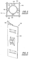
- Figure 2 presents a cross-sectional top plan view of one of the aforementioned four-walled cells 116, with a fuel rod 130 contained therein. As shown, the springs 122 and dimples 124 extend inwardly within the four-walled cell 116 to engage and provide support for the fuel rod 130, as previously discussed.
- a coolant such as for example, water
- the temperature of the coolant varies as it travels upwards, absorbing thermal energy from the fuel rods.
- the coolant may be partially overheated, which can adversely affect the thermal performance of the fuel assembly and reduce the output power of the fuel rods.
- One way of alleviating these partially overheated regions is to design the spacer grids to more effectively deflect and mix the coolant as it flows upwards through the fuel assembly, thereby promoting a more uniform distribution of coolant temperature.
- Such a design can be accomplished by attaching "mixing vanes" to the top, downstream portion of the grid straps that comprise the spacer grid, as shown.
- the mixing vanes are intended to promote the flow of coolant in a lateral direction as well as a longitudinal direction along the fuel rod axes. This flow pattern allows the coolant to more effectively move between the fuel rods, and between the lower temperature regions and the partially overheated regions of the fuel assembly.
- Figure 3 presents a partial perspective view of a grid strap 140 and conventional PWR mixing vane 142, wherein the mixing vane 142 is disposed at the top, downstream portion of a cell wall 144.
- BWR vanes are typically much smaller in size.
- Other conventional mixing vane designs are disclosed in U.S. Patent No. 5,440,599 to Rodack et al. , U.S. Patent No. 6,807,246 to Kim et al. , U.S. Patent No. 3,862,000 to Pugh et al. , U.S. Patent No. 4, 758,403 to Noailly , U.S. Patent No.
- the present invention provides a spacer grid for a nuclear fuel assembly having a plurality of elongated fuel rods.
- the spacer grid employs novel mixing vanes which include an upper piece and a lower piece, which are connected to a middle ligament that is coupled to the top or downstream portion of a grid strap forming the spacer grid.
- each four-walled cell of the spacer grid may contain four mixing vanes - one positioned at the top, downstream portion of each wall.
- the upper piece, lower piece, and middle ligament may be bent, rotated, and/or twisted into various positions to more effectively mix the coolant and affect the coolant's flow as it moves upwards through the fuel assembly.
- the mixing vane has an "S" shape when viewed from an end elevational vantage point. More specifically, the middle ligament is positioned parallel to the longitudinal axes of the fuel rods, the upper piece is bent towards the fuel rod, and the lower piece is bent away from the fuel rod, thereby defining the general S-shape. In another preferred embodiment, the mixing vane has a parabolic shape when viewed from the end elevational vantage point. A nuclear fuel assembly employing such mixing vanes, is also disclosed.
- An object of the present invention is to provide a mixing vane that is tunable in order to affect ( i.e ., control or adjust) and thus optimize for the particular application at hand the coolant flow pattern that is formed, rather than merely deflecting the coolant flow.
- Another object of the present invention is to provide a mixing vane that promotes optimized even and sustained interchannel mixing.
- Yet another object of the present invention is to provide a mixing vane that more effectively mixes coolant as it moves upwards through the fuel assembly, thereby mitigating regions of varying coolant temperature.
- a further object of the present invention is to provide mixing vane that is easily manufactured using conventional die technology.
- Another object of the present invention is to provide a mixing vane with an upper piece, a lower piece, and a middle ligament, that are easily tuned or adjusted by bending, rotating, and twisting, in order to optimize the coolant flow.
- Figure 1 is a partial perspective view of a conventional spacer grid for use with a fuel assembly having a square cross-section.
- Figure 2 is a cross-sectional view of a four-walled cell and fuel rod located within a conventional spacer grid.
- Figure 3 is a partial perspective view of a grid strap and conventional mixing vane.
- Figures 4a and 4b are partial elevational views of two types of perpendicularly positioned, interlocking grid straps in accordance with a preferred embodiment of the present invention.
- Figure 5 is an elevational view of a portion of one grid strip which defines a single cell wall, and mixing vane that has been bent in accordance with a preferred embodiment of the present invention.
- Figures 6a and 6b are partial perspective and top plan views, respectively, of a grid strap intersection of a spacer grid in accordance with a preferred embodiment of the present invention.
- Figure 7 is a partial perspective view of a portion of a spacer grid and a single four-walled cell thereof in accordance with a preferred embodiment of the present invention.
- FIGS 8a and 8b are schematic views of an S-shaped mixing vane with various bend angles in accordance with preferred embodiments of the present invention.
- Figure 9 is a schematic view of an S-shaped mixing vane that has been rotated in accordance with preferred embodiments of the present invention.
- Figures 10a and 10b are schematic views of S-shaped mixing vanes that have been twisted in accordance with preferred embodiments of the present invention.
- each mixing vane is contemplated as being formed from the grid strap material and connected to the grid strap as an integral component, that the mixing vanes could also be connected by welding, brazing, or mechanically securing them to the grid straps.
- the mixing vanes can also be made from any known or suitable material (e.g. , without limitation zirconium alloy or nickel-steel alloy).
- the terms “bend” and “bend angle” are used when referring to a bend in the upper or lower piece of the mixing vane.
- the terms “rotate” and “rotation angle” are used when referring to a rotation of the middle ligament.
- the terms “twist” and “degree of twist” are used when referring to a twist of the upper piece, lower piece, or middle ligament.
- FIGs 4a, 4b, 5, 6a, 6b and 7 illustrate a preferred embodiment of the present invention in which the grid straps of a spacer grid include generally S-shaped mixing vanes. While the present invention is not limited to any particular number of mixing vanes, four mixing vanes are positioned around each fuel rod and four-walled cell in the preferred embodiment (best shown in Figure 7).
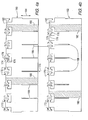
- Figures 4a and 4b are partial elevational views of two types of perpendicularly positioned, interlocking grid straps 160, 162.
- a plurality of these grid straps 160, 162 are placed perpendicular to each other and connected together such that the downwardly positioned notches 166 on the first type of grid strap 160, shown in Figure 4a, engage the upwardly positioned notches 168 on the second type of grid strap 162, shown in Figure 4b.
- the location where the notches 166, 168 are connected is known as a grid strap intersection 170 ( Figures 6a and 6b).
- Each grid strap 160, 162 includes a plurality of mixing vanes 172, which are shown in a flattened state in the unassembled views of Figures 4a and 4b.
- Each mixing vane includes an upper piece 174 and a lower piece 176 that are connected to a middle ligament 178.
- the middle ligament 178 is connected to the grid strap 160, 162.
- each cell wall 180 two cell walls 180 are shown in cross-hatch in Figures 4a and 4b) of each grid strap 160, 162 preferably contains a single mixing vane 172.
- the mixing vane 172 may be connected to the grid strap 160, 162 at its top or "downstream" portion 182.
- the mixing vane 172 is preferably connected to the grid strap 160, 162 so that the middle ligament extends outward from the grid strap 160,162 in a direction that is substantially orthogonal with respect to the longitudinal axis 184 of the cell wall 180.
- the grid straps 160, 162 in the examples of Figures 4a and 4b are shown without springs and dimples in the cell walls 180. It will, however, be appreciated that any suitable number and configuration of dimples and springs could be employed (see, for example, Figure 7).
- the mixing vanes 172 of Figures 4a and 4b are shown in a flattened position, prior to being assembled, the mixing vanes 172 are preferably bent and/or twisted into various positions to positively affect and thus optimize the flow of coolant as it moves through the fuel assembly. More specifically, the vanes 172 may be adjusted or fine tuned in order to optimize the coolant flow, as desired, for the particular application in which they are being employed.
- Figure 5 is an elevational view of a single cell wall 180 and mixing vane 172 that has been bent in accordance with a preferred embodiment of the invention.
- the upper piece 174 of the vane 172 has been bent at its connection with the middle ligament 178, and placed at a "bend angle" of approximately +45 degrees from the vertical.
- the vertical direction is defined by the longitudinal axis 184 of the cell wall 180.
- the lower piece 176 of the vane 172 has also been bent at its connection with the middle ligament 178, and placed at a "bend angle" of approximately -45 degrees from the vertical.
- the middle ligament 178 has been bent at its connection with the grid strap 160 and placed at a "rotation angle" of approximately -45 degrees with respect to the plane of the grid strap 160.
- a negative rotation angle for the middle ligament 178 indicates a counterclockwise rotation when viewed from the top of the fuel assembly, and a positive rotation angle indicates a clockwise rotation.
- the middle ligament 178 in the example shown, remains vertically aligned and parallel to the longitudinal axis 184 of the cell wall 180.
- the mixing vane 172 appears to have an S-shape when it is viewed directly from the side ( i.e., from the left end with respect to Figure 5).
- the grid strap 160 of Figure 5 does not show springs or dimples in cell wall 180, it will be appreciated that any suitable number and configuration of dimples and springs could be employed (see, for example, Figure 7).
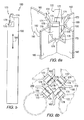
- Figure 6a is a partial perspective view of a grid strap intersection 170 of the spacer grid
- Figure 6b is a top plan view of such intersection 170.
- the grid strap intersection 170 occurs where two grid straps 160, 162 have been perpendicularly positioned and interlocked together using their upwardly and downwardly positioned notches 166,168 ( Figures 4a and 4b).
- each grid strap cell wall 180 contains a single mixing vane 172
- the grid strap intersection 170 is surrounded with a total of four mixing vanes 172, two per grid strap 160, 162.
- the upper piece 174 of each vane 172 has been bent at its connection with the middle ligament 178, and placed at a bend angle of approximately +45 degrees from the vertical.
- each vane 172 has been bent at its connection with the middle ligament 178, and angled approximately -45 degrees from the vertical.
- a positive angle for the upper or lower piece 174, 176 indicates that the piece has been bent away from the grid strap intersection 170, and towards an adjacent fuel rod (not shown).
- a negative angle for the upper or lower piece 174, 176 indicates that the piece has been bent towards the grid strap intersection 170, and away from an adjacent fuel rod (not shown).
- the middle ligament 178 of each vane 172 has been bent at its connection with the grid strap 160, 162, and placed at a rotation angle of approximately +30 degrees from the plane of each grid strap 160, 162.
- a positive rotation angle for the middle ligament 178 indicates a clockwise rotation when viewed from a top plan view perspective (see, for example, Figure 6b), and a negative rotation angle indicates a counterclockwise rotation.
- FIG. 6b The top plan view of Figure 6b further shows the interaction of the mixing vanes 172 with fuel rods 210 of the fuel assembly.
- One complete fuel rod 210 shown in simplified form in phantom line drawing) and portions of the three adjacent fuel rods 210, are shown.
- Figure 7 is a partial perspective view of a spacer grid 200 in accordance with the invention.
- the spacer grid 200 in accordance with the invention forms any known or suitable array of a plurality of four-walled cells 202, similar for example, to the spacer grid 100 shown in Figure 1.
- Figure 7 and, in particular mixing vanes 172 are not drawn to scale.
- the four-walled cell 202 occurs where four grid straps 160, 162, 164, 165 interlock in a generally perpendicular configuration to create an opening for supporting a fuel rod 210 (shown in simplified form in phantom line drawing) therein.
- each grid strap 160, 162, 164, 165 includes a plurality of springs 186 and dimples 188 of any known or suitable orientation, for securing the fuel rod 210.
- each cell wall 180 includes a single mixing vane 172, a total of four mixing vanes 172 surround the fuel rod 210 and four-walled cell 202.
- the upper piece 174 of each vane 172 has a bend angle of approximately +45 degrees from the vertical 184. The positive angle indicates that the piece has been bent towards the fuel rod 210.
- the lower piece 176 of each vane 172 has a bend angle of approximately-45 degrees from the vertical.
- the negative angle indicates that the piece has been bent away from the fuel rod 210.
- the middle ligament 178 of each vane 172 has a rotation angle of approximately +45 degrees from the plane of each grid strap 160, 162, 164, 165, with the positive angle indicating a clockwise direction of rotation when viewed from a top plan view perspective.
- the spacer grid 200 includes a plurality of perpendicular, interlocking grid straps 160, 162, 164, 165 that define the aforementioned grid strap intersections 170 ( Figures 6a and 6b) and the four-walled cells 202.
- each mixing vane 172 appears to have an S-shape. It is in this manner ( i.e.
- the exemplary mixing vanes 172 assist in mixing coolant to create optimized even and sustained mixing (e.g., without limitation, a strong swirl and interchannel mixing) of the coolant as it moves upwards through the fuel assembly.
- the present invention is not, however, limited to the embodiment shown hereinbefore. It will be appreciated that a wide variety of other mixing vane configurations are within the scope of the invention.
- the upper and lower pieces of the mixing vane can have any suitable positive or negative bend angle 220, 222 with respect to the vertical ( i.e. , the longitudinal axis 184 of the cell wall 180), ranging from about 0 to about +90 degrees or about 0 to about -90 degrees.
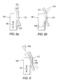
- Figure 8a is a side view of an S-shaped mixing vane 172 which shows how bend angles 220, 222 of the upper piece 174 and lower piece 176 are measured from the vertical or longitudinal axis 184 of the grid strap 160.
- Figure 8b illustrates example alternative bends 224, 226 for the upper piece 174 and lower piece 176 of the mixing vane 172 (with the alternatives shown in dashed line drawing).
- the upper piece 174 and/or lower piece 176 have bends 224, 226 ranging from about 0 to +45 degrees or about 0 to -45 degrees.
- the upper and lower pieces 174, 176 could alternatively both be bent towards an adjacent fuel rod, in order to form a parabolic-shaped mixing vane (not shown). It will also be appreciated that, rather than being bent, the upper and/or lower pieces 174, 176 could remain unbent ( i.e. , vertical at 0 degrees). It will still further be appreciated that while the upper and lower pieces 174, 176 are preferably bent at their connection with the middle ligament 178, a bend could occur at any location along the upper and lower piece 174, 176, and/or each piece 174, 176 can contain multiple bends (not shown).
- Figure 9 is a side view of an S-shaped mixing vane 172 which shows how the rotation angle 228, as previously defined herein, for the middle ligament 178 is measured from the vertical or longitudinal axis 184 of the grid strap ( i.e., 160).
- the middle ligament 178 may have any positive or negative rotation angle 228 with respect to the vertical, ranging from about 0 to +90 degrees or from about 0 to -90 degrees.
- the middle ligament 178 is rotated from about 0 to +45 degrees (towards a fuel rod) or from about 0 to -45 degrees (away from a fuel rod).
- the middle ligament 178 may remain at 0 degrees, parallel to the vertical. Additionally, while the example of Figure 9 shows a pivot point 230 that is located approximately at the center of the middle ligament 178, the pivot point may occur at any location on the middle ligament 178.
- a middle ligament 178 may also contain multiple pivot points (not shown) and therefore multiple rotation angles (not shown).
- the upper piece 174, lower piece 176, and middle ligament 178 may be "twisted" (i.e., subjected to torsion) in a clockwise or counterclockwise direction, as shown in Figures 10a and 10b.
- Figure 10a is a side view of two mixing vanes 172, wherein the upper piece 174 of each vane 172 is twisted.
- the "degree of twist” may range from about 0 to +90 degrees or from 0 to about -90 degrees (either clockwise or counterclockwise) with respect to axis 173.
- any suitable combination of twisting of one or both of the upper and lower pieces 174, 176 could be employed.
- Figure 10b is a partial perspective view of four mixing vanes 172 surrounding a grid strap intersection 170.
- the upper pieces 174 of two opposing mixing vanes 172 are twisted, while the upper pieces of the other two mixing vanes 172 are not.
- the degree of twist ranges from about 0 to +90 degrees or from about 0 to -90 degrees, in either a clockwise or counterclockwise direction.
- a single upper piece 174, lower piece 176, or middle ligament 178 may include multiple twists, and that the various mixing vanes 172 and components thereof, of a particular intersection 170 may have any suitable combination of bend, twist, and/or rotation.
- a spacer grid may contain fuel rods that are surrounded with mixing vanes and fuel rods that are not. Not every four-walled cell of a spacer grid is required to include a mixing vane.
- a fuel rod may be surrounded with anywhere from zero to four mixing vanes.
- a fuel rod is preferably surrounded with two or four mixing vanes.
- each mixing vane it is also preferable for the upper piece of each mixing vane to bend towards the fuel rod, and for the lower piece of each mixing vane to bend away from the fuel rod, although the mixing vanes in a given spacer grid may vary with respect to their bends, rotations, and twists. At least one upper piece may be twisted and/or bent with respect to the longitudinal axis of the cell walls, at least one lower piece may be twisted and/or bent with respect to the longitudinal axis of the cell walls, and/or at least one middle ligament may be twisted and/or bent with respect to a plane on which the grid strap resides.
Landscapes
- Physics & Mathematics (AREA)
- Engineering & Computer Science (AREA)
- Plasma & Fusion (AREA)
- General Engineering & Computer Science (AREA)
- High Energy & Nuclear Physics (AREA)
- Fuel Cell (AREA)
- Apparatus Associated With Microorganisms And Enzymes (AREA)
Abstract
Description
- The present invention relates generally to nuclear reactors and, more particularly, to spacer grids for a nuclear fuel assembly, including mixing vanes to effectively mix coolant as it flows through the fuel assembly.
- Nuclear fuel assemblies for light water nuclear reactors, such as, for example, pressurized water reactors (PWRs) and boiling water reactors (BWRs), generally include a plurality of fuel rods with circular cross-sections that are arranged parallel to one another at regularly or irregularly spaced intervals. Each fuel rod comprises a stack of fuel pellets (e.g., uranium oxide pellets) surrounded with cladding that is made from zirconium alloy or other suitable material. The fuel rods are held at the spaced intervals with respect to one another by one or more spacer grids. Each spacer grid includes a plurality of interlocking grid straps that are welded together to form an array of four-walled cells in an "egg-crate" configuration. A fuel rod may be contained within each of the four-walled cells. The entire fuel assembly typically has a square cross-section with a 14x14, 15x15, 16x16, or 17x17 array of fuel rods. One or more outer straps may encircle the periphery of each spacer grid.
- Figure 1 presents a partial perspective view of a
conventional spacer grid 100 for afuel assembly 102. Thespacer grid 100 includes two sets of perpendicularly placedgrid straps grid strap grid straps walled cells 116. Each four-walled cell 116 contains fourintersections 118. Thegrid straps intersections 118. The purpose of the four-walled cell 116 is to support a single fuel rod 130 (Figure 2) in the square array of thefuel assembly 102. The periphery of thegrid straps outer straps 120. A plurality ofsprings 122 and a plurality ofdimples 124 are integrally formed on, or attached to, thegrid straps walled cell 116. Thesprings 122 anddimples 124 provide support structures for contacting the fuel rod cladding and holding it within the four-walled cell 116. - Figure 2 presents a cross-sectional top plan view of one of the aforementioned four-
walled cells 116, with afuel rod 130 contained therein. As shown, thesprings 122 anddimples 124 extend inwardly within the four-walled cell 116 to engage and provide support for thefuel rod 130, as previously discussed. - When the PWR or BWR is in use, a coolant, such as for example, water, flows from the bottom of the fuel assembly upwards through the spaces between the fuel rods. The temperature of the coolant varies as it travels upwards, absorbing thermal energy from the fuel rods. At locations adjacent to the fuel rods, the coolant may be partially overheated, which can adversely affect the thermal performance of the fuel assembly and reduce the output power of the fuel rods. One way of alleviating these partially overheated regions is to design the spacer grids to more effectively deflect and mix the coolant as it flows upwards through the fuel assembly, thereby promoting a more uniform distribution of coolant temperature. Such a design can be accomplished by attaching "mixing vanes" to the top, downstream portion of the grid straps that comprise the spacer grid, as shown. The mixing vanes are intended to promote the flow of coolant in a lateral direction as well as a longitudinal direction along the fuel rod axes. This flow pattern allows the coolant to more effectively move between the fuel rods, and between the lower temperature regions and the partially overheated regions of the fuel assembly.
- Figure 3 presents a partial perspective view of a
grid strap 140 and conventionalPWR mixing vane 142, wherein themixing vane 142 is disposed at the top, downstream portion of acell wall 144. It should be noted that although they are generally similar in configuration to the PWR vane shown, BWR vanes are typically much smaller in size. Other conventional mixing vane designs are disclosed inU.S. Patent No. 5,440,599 to Rodack et al. ,U.S. Patent No. 6,807,246 to Kim et al. ,U.S. Patent No. 3,862,000 to Pugh et al. ,U.S. Patent No. 4, 758,403 to Noailly ,U.S. Patent No. 5,299,245 to Aldrich ,U.S. Patent No. 5, 283,821 to Karoutas ,U.S. Patent No. 6,606,369 to Smith III et al. ,U.S. Patent No. 6,278,759 to Yoon et al. ,U.S. Patent No. 4,692,302 to DeMario et al. ,U.S. Patent No. 5,265,140 to Perrotti ,U.S. Patent No. 6,236,702 to Chun et al. , andU.S. Patent No. 5,339,341 to King et al. Nozzle-type mixing vanes are disclosed inU.S. Patent No. 4,726,926 to Patterson et al. andU.S. Patent No. 6,130,927 to Kang et al. - Conventional mixing vanes, however, tend to be restricted in the ways in which they deflect the flow of coolant as it moves upwards through the fuel assembly. They do not provide a robust means for adjusting or tuning the vanes in order to optimize the flow pattern that is formed. As a result, conventional mixing vanes cannot effectively achieve the most desirable type of coolant flow-even and sustained mixing-for the particular application at hand. Thus, there exists a need for a new type of mixing vane that guides the coolant in a desired flow pattern to more effectively mix the coolant as it moves upward through the fuel assembly.
- The present invention provides a spacer grid for a nuclear fuel assembly having a plurality of elongated fuel rods. The spacer grid employs novel mixing vanes which include an upper piece and a lower piece, which are connected to a middle ligament that is coupled to the top or downstream portion of a grid strap forming the spacer grid. Although the present invention is not limited to any particular number of mixing vanes, in a preferred embodiment, each four-walled cell of the spacer grid may contain four mixing vanes - one positioned at the top, downstream portion of each wall. The upper piece, lower piece, and middle ligament may be bent, rotated, and/or twisted into various positions to more effectively mix the coolant and affect the coolant's flow as it moves upwards through the fuel assembly. In a preferred embodiment, the mixing vane has an "S" shape when viewed from an end elevational vantage point. More specifically, the middle ligament is positioned parallel to the longitudinal axes of the fuel rods, the upper piece is bent towards the fuel rod, and the lower piece is bent away from the fuel rod, thereby defining the general S-shape. In another preferred embodiment, the mixing vane has a parabolic shape when viewed from the end elevational vantage point. A nuclear fuel assembly employing such mixing vanes, is also disclosed.
- An object of the present invention is to provide a mixing vane that is tunable in order to affect (i.e., control or adjust) and thus optimize for the particular application at hand the coolant flow pattern that is formed, rather than merely deflecting the coolant flow.
- Another object of the present invention is to provide a mixing vane that promotes optimized even and sustained interchannel mixing.
- Yet another object of the present invention is to provide a mixing vane that more effectively mixes coolant as it moves upwards through the fuel assembly, thereby mitigating regions of varying coolant temperature.
- A further object of the present invention is to provide mixing vane that is easily manufactured using conventional die technology.
- Another object of the present invention is to provide a mixing vane with an upper piece, a lower piece, and a middle ligament, that are easily tuned or adjusted by bending, rotating, and twisting, in order to optimize the coolant flow.
- These and other objects of the present invention will become more readily apparent from the following detailed description and appended claims.
- Figure 1 is a partial perspective view of a conventional spacer grid for use with a fuel assembly having a square cross-section.
- Figure 2 is a cross-sectional view of a four-walled cell and fuel rod located within a conventional spacer grid.
- Figure 3 is a partial perspective view of a grid strap and conventional mixing vane.
- Figures 4a and 4b are partial elevational views of two types of perpendicularly positioned, interlocking grid straps in accordance with a preferred embodiment of the present invention.
- Figure 5 is an elevational view of a portion of one grid strip which defines a single cell wall, and mixing vane that has been bent in accordance with a preferred embodiment of the present invention.
- Figures 6a and 6b are partial perspective and top plan views, respectively, of a grid strap intersection of a spacer grid in accordance with a preferred embodiment of the present invention.
- Figure 7 is a partial perspective view of a portion of a spacer grid and a single four-walled cell thereof in accordance with a preferred embodiment of the present invention.
- Figures 8a and 8b are schematic views of an S-shaped mixing vane with various bend angles in accordance with preferred embodiments of the present invention.
- Figure 9 is a schematic view of an S-shaped mixing vane that has been rotated in accordance with preferred embodiments of the present invention.
- Figures 10a and 10b are schematic views of S-shaped mixing vanes that have been twisted in accordance with preferred embodiments of the present invention.
- The description contained herein primarily refers to the use of a mixing vane having a generally rectangular shape. It will, however, be appreciated the mixing vanes may have any suitable shape, size, or dimensions. It will also be appreciated that although each mixing vane is contemplated as being formed from the grid strap material and connected to the grid strap as an integral component, that the mixing vanes could also be connected by welding, brazing, or mechanically securing them to the grid straps. The mixing vanes can also be made from any known or suitable material (e.g., without limitation zirconium alloy or nickel-steel alloy). It will further be appreciated that the Figures provided herein are provided for simplicity of illustration of only certain examples or variations of mixing vanes in accordance with the invention, and are not meant to be limiting upon the scope of the invention. It will also be appreciated that the Figures and, in particular, certain features depicted therein, are not drawn to scale.
- Directional phrases used herein, such as, for example, clockwise, counterclockwise, top, bottom, upper, lower and derivatives thereof, relate to the orientation of the elements shown in the drawings and are not limiting upon the claims unless expressly recited therein.
- As used herein, the terms "bend" and "bend angle" are used when referring to a bend in the upper or lower piece of the mixing vane. The terms "rotate" and "rotation angle" are used when referring to a rotation of the middle ligament. The terms "twist" and "degree of twist" are used when referring to a twist of the upper piece, lower piece, or middle ligament.
- As employed herein, the statement that two or more parts are "coupled" together shall mean that the parts are joined together either directly or joined through one or more intermediate parts.
- Figures 4a, 4b, 5, 6a, 6b and 7 illustrate a preferred embodiment of the present invention in which the grid straps of a spacer grid include generally S-shaped mixing vanes. While the present invention is not limited to any particular number of mixing vanes, four mixing vanes are positioned around each fuel rod and four-walled cell in the preferred embodiment (best shown in Figure 7).
- Figures 4a and 4b are partial elevational views of two types of perpendicularly positioned, interlocking grid straps 160, 162. To form the spacer grid 200 (Figure 7), a plurality of these grid straps 160, 162 are placed perpendicular to each other and connected together such that the downwardly positioned
notches 166 on the first type ofgrid strap 160, shown in Figure 4a, engage the upwardlypositioned notches 168 on the second type ofgrid strap 162, shown in Figure 4b. The location where thenotches grid strap vanes 172, which are shown in a flattened state in the unassembled views of Figures 4a and 4b. - Each mixing vane includes an
upper piece 174 and alower piece 176 that are connected to amiddle ligament 178. Themiddle ligament 178 is connected to thegrid strap vanes 172, each cell wall 180 (twocell walls 180 are shown in cross-hatch in Figures 4a and 4b) of eachgrid strap single mixing vane 172. The mixingvane 172 may be connected to thegrid strap portion 182. The mixingvane 172 is preferably connected to thegrid strap longitudinal axis 184 of thecell wall 180. For simplicity of illustration, the grid straps 160, 162 in the examples of Figures 4a and 4b are shown without springs and dimples in thecell walls 180. It will, however, be appreciated that any suitable number and configuration of dimples and springs could be employed (see, for example, Figure 7). It will also be appreciated that although the mixingvanes 172 of Figures 4a and 4b are shown in a flattened position, prior to being assembled, the mixingvanes 172 are preferably bent and/or twisted into various positions to positively affect and thus optimize the flow of coolant as it moves through the fuel assembly. More specifically, thevanes 172 may be adjusted or fine tuned in order to optimize the coolant flow, as desired, for the particular application in which they are being employed. - Figure 5 is an elevational view of a
single cell wall 180 and mixingvane 172 that has been bent in accordance with a preferred embodiment of the invention. Specifically, theupper piece 174 of thevane 172 has been bent at its connection with themiddle ligament 178, and placed at a "bend angle" of approximately +45 degrees from the vertical. The vertical direction is defined by thelongitudinal axis 184 of thecell wall 180. Thelower piece 176 of thevane 172 has also been bent at its connection with themiddle ligament 178, and placed at a "bend angle" of approximately -45 degrees from the vertical. Themiddle ligament 178 has been bent at its connection with thegrid strap 160 and placed at a "rotation angle" of approximately -45 degrees with respect to the plane of thegrid strap 160. A negative rotation angle for themiddle ligament 178 indicates a counterclockwise rotation when viewed from the top of the fuel assembly, and a positive rotation angle indicates a clockwise rotation. Despite its rotation, themiddle ligament 178, in the example shown, remains vertically aligned and parallel to thelongitudinal axis 184 of thecell wall 180. Thus, the mixingvane 172 appears to have an S-shape when it is viewed directly from the side (i.e., from the left end with respect to Figure 5). As noted previously with respect to Figures 4a and 4b, although thegrid strap 160 of Figure 5 does not show springs or dimples incell wall 180, it will be appreciated that any suitable number and configuration of dimples and springs could be employed (see, for example, Figure 7). - Figure 6a is a partial perspective view of a
grid strap intersection 170 of the spacer grid, and Figure 6b is a top plan view ofsuch intersection 170. As noted previously, thegrid strap intersection 170 occurs where twogrid straps strap cell wall 180 contains asingle mixing vane 172, thegrid strap intersection 170 is surrounded with a total of four mixingvanes 172, two pergrid strap upper piece 174 of eachvane 172 has been bent at its connection with themiddle ligament 178, and placed at a bend angle of approximately +45 degrees from the vertical. Thelower piece 176 of eachvane 172 has been bent at its connection with themiddle ligament 178, and angled approximately -45 degrees from the vertical. A positive angle for the upper orlower piece grid strap intersection 170, and towards an adjacent fuel rod (not shown). A negative angle for the upper orlower piece grid strap intersection 170, and away from an adjacent fuel rod (not shown). This may be further appreciated and understood with reference to the top plan view of Figure 6b. Themiddle ligament 178 of eachvane 172 has been bent at its connection with thegrid strap grid strap middle ligament 178 indicates a clockwise rotation when viewed from a top plan view perspective (see, for example, Figure 6b), and a negative rotation angle indicates a counterclockwise rotation. - The top plan view of Figure 6b further shows the interaction of the mixing
vanes 172 withfuel rods 210 of the fuel assembly. One complete fuel rod 210 (shown in simplified form in phantom line drawing) and portions of the threeadjacent fuel rods 210, are shown. - Figure 7 is a partial perspective view of a
spacer grid 200 in accordance with the invention. For simplicity of illustration, only one complete four-walled cell 202 of thespacer grid 200 is shown. It will be appreciated, however, that thespacer grid 200 in accordance with the invention forms any known or suitable array of a plurality of four-walled cells 202, similar for example, to thespacer grid 100 shown in Figure 1. It will also be appreciated that Figure 7 and, inparticular mixing vanes 172, are not drawn to scale. The four-walled cell 202 occurs where fourgrid straps grid strap springs 186 anddimples 188 of any known or suitable orientation, for securing thefuel rod 210. Since eachcell wall 180 includes asingle mixing vane 172, a total of four mixingvanes 172 surround thefuel rod 210 and four-walled cell 202. Theupper piece 174 of eachvane 172 has a bend angle of approximately +45 degrees from the vertical 184. The positive angle indicates that the piece has been bent towards thefuel rod 210. Thelower piece 176 of eachvane 172 has a bend angle of approximately-45 degrees from the vertical. The negative angle indicates that the piece has been bent away from thefuel rod 210. Themiddle ligament 178 of eachvane 172 has a rotation angle of approximately +45 degrees from the plane of eachgrid strap - Accordingly, the
spacer grid 200 includes a plurality of perpendicular, interlocking grid straps 160, 162, 164, 165 that define the aforementioned grid strap intersections 170 (Figures 6a and 6b) and the four-walled cells 202. When viewed from an end elevational vantage point, each mixingvane 172 appears to have an S-shape. It is in this manner (i.e., theupper piece 174 bending towardfuel rod 210, thelower piece 176 bending toward thefuel rod 210, and themiddle ligament 178 rotating toward the fuel rod) that theexemplary mixing vanes 172 assist in mixing coolant to create optimized even and sustained mixing (e.g., without limitation, a strong swirl and interchannel mixing) of the coolant as it moves upwards through the fuel assembly. - The present invention is not, however, limited to the embodiment shown hereinbefore. It will be appreciated that a wide variety of other mixing vane configurations are within the scope of the invention. For example, the upper and lower pieces of the mixing vane can have any suitable positive or
negative bend angle longitudinal axis 184 of the cell wall 180), ranging from about 0 to about +90 degrees or about 0 to about -90 degrees. - Figure 8a is a side view of an S-shaped
mixing vane 172 which shows how bend angles 220, 222 of theupper piece 174 andlower piece 176 are measured from the vertical orlongitudinal axis 184 of thegrid strap 160. Figure 8b illustrates example alternative bends 224, 226 for theupper piece 174 andlower piece 176 of the mixing vane 172 (with the alternatives shown in dashed line drawing). In the example of Figure 8b, theupper piece 174 and/orlower piece 176 havebends lower pieces lower pieces lower pieces middle ligament 178, a bend could occur at any location along the upper andlower piece piece - Figure 9 is a side view of an S-shaped
mixing vane 172 which shows how therotation angle 228, as previously defined herein, for themiddle ligament 178 is measured from the vertical orlongitudinal axis 184 of the grid strap (i.e., 160). It will be appreciated that themiddle ligament 178 may have any positive ornegative rotation angle 228 with respect to the vertical, ranging from about 0 to +90 degrees or from about 0 to -90 degrees. For example, in one embodiment, shown in dashed line drawing, themiddle ligament 178 is rotated from about 0 to +45 degrees (towards a fuel rod) or from about 0 to -45 degrees (away from a fuel rod). However, as shown in solid line drawing, rather than being rotated, themiddle ligament 178 may remain at 0 degrees, parallel to the vertical. Additionally, while the example of Figure 9 shows apivot point 230 that is located approximately at the center of themiddle ligament 178, the pivot point may occur at any location on themiddle ligament 178. Amiddle ligament 178 may also contain multiple pivot points (not shown) and therefore multiple rotation angles (not shown). - In addition to being bent or rotated, the
upper piece 174,lower piece 176, andmiddle ligament 178 may be "twisted" (i.e., subjected to torsion) in a clockwise or counterclockwise direction, as shown in Figures 10a and 10b. Figure 10a is a side view of two mixingvanes 172, wherein theupper piece 174 of eachvane 172 is twisted. The "degree of twist" may range from about 0 to +90 degrees or from 0 to about -90 degrees (either clockwise or counterclockwise) with respect toaxis 173. Although only theupper pieces 174 are twisted in the example of Figure 10a, it will be appreciated that any suitable combination of twisting of one or both of the upper andlower pieces - Figure 10b is a partial perspective view of four mixing
vanes 172 surrounding agrid strap intersection 170. In the example of Figure 10b, theupper pieces 174 of two opposing mixingvanes 172 are twisted, while the upper pieces of the other two mixingvanes 172 are not. The degree of twist ranges from about 0 to +90 degrees or from about 0 to -90 degrees, in either a clockwise or counterclockwise direction. It will be appreciated that, in accordance with the invention, a singleupper piece 174,lower piece 176, ormiddle ligament 178 may include multiple twists, and that thevarious mixing vanes 172 and components thereof, of aparticular intersection 170 may have any suitable combination of bend, twist, and/or rotation. - Although the description contained hereinabove primarily refers to the use of four mixing vanes around a single fuel rod and four-walled cell, the present invention is not limited to any particular number of mixing vanes or placement of mixing vanes within the spacer grid. A spacer grid may contain fuel rods that are surrounded with mixing vanes and fuel rods that are not. Not every four-walled cell of a spacer grid is required to include a mixing vane. A fuel rod may be surrounded with anywhere from zero to four mixing vanes. A fuel rod is preferably surrounded with two or four mixing vanes. It is also preferable for the upper piece of each mixing vane to bend towards the fuel rod, and for the lower piece of each mixing vane to bend away from the fuel rod, although the mixing vanes in a given spacer grid may vary with respect to their bends, rotations, and twists. At least one upper piece may be twisted and/or bent with respect to the longitudinal axis of the cell walls, at least one lower piece may be twisted and/or bent with respect to the longitudinal axis of the cell walls, and/or at least one middle ligament may be twisted and/or bent with respect to a plane on which the grid strap resides.
- Whereas particular embodiments of this invention have been described above for purposes of illustration, it will be evident to those skilled in the art that numerous variations of the details of the present invention may be made without departing from the invention as defined in the appended claims.
Claims (11)
- A spacer grid for a nuclear fuel assembly including a plurality of elongated fuel rods and adapted to receive a coolant flowing over the fuel rods, the spacer grid comprising:a plurality of interlocking grid straps forming a plurality of four-walled cells structured to support the fuel rods therein, the four-walled cells each including four cell walls having a longitudinal axis; anda plurality of mixing vanes coupled to each of the grid straps, each of the mixing vanes including a middle ligament coupled to a top portion of a corresponding one of the grid straps, an upper piece coupled to an upper portion of the middle ligament, and a lower piece coupled to a lower portion of the middle ligament, wherein each of the upper piece, the lower piece, and the middle ligament has a predetermined bend angle, a predetermined rotation angle, and a predetermined degree of twist, in order to provide a predetermined affect on the coolant as it flows over the fuel rods and through the fuel assembly.
- The spacer grid of Claim 1, wherein the middle ligament extends in a substantially orthogonal direction with respect to the longitudinal axis of the cell wall.
- The spacer grid of Claim 1, wherein at least one of the upper piece and the lower piece of at least one of the mixing vanes is bent with respect to the longitudinal axis of the cell wall.
- The spacer grid of Claim 1, wherein each of the grid straps has a corresponding plane; and wherein the middle ligament of at least one of the mixing vanes is rotated with respect to the plane.
- The spacer grid of Claim 1, wherein the middle ligament includes at least one pivot point; and wherein the middle ligament is twisted with respect to at least one of the at least one pivot point.
- The spacer grid of Claim 1, wherein at least one of the upper piece and the lower piece of at least one mixing vane is twisted.
- The spacer grid of Claim 1, wherein the upper piece is bent towards an adjacent one of the fuel rods; and wherein the lower piece is bent away from the adjacent one of the fuel rods, in order to provide the mixing vane with a generally S-shaped configuration.
- The spacer grid of Claim 1, wherein the upper piece is bent towards an adjacent one of the fuel rods; and wherein the lower piece is also bent toward the adjacent one of the fuel rods, in order to provide the mixing vane with a generally parabolic shape.
- The spacer grid of Claim 1, wherein one said mixing vane is coupled to each cell wall of the spacer grid.
- The spacer grid of Claim 1, wherein the grid straps interlock in a generally perpendicular configuration in order to form the four-walled cells; and wherein at least one of the four-walled cells of the spacer grid includes four mixing vanes.
- A nuclear fuel assembly comprising a plurality of elongated fuel rods and adapted to receive a coolant flowing upward over the fuel rods and through the fuel assembly; and including at least one spacer grid according to any of claims 1 to 10 for securing the elongated fuel rods in an organized array.
Applications Claiming Priority (1)
| Application Number | Priority Date | Filing Date | Title |
|---|---|---|---|
| US11/372,431 US7548602B2 (en) | 2006-03-09 | 2006-03-09 | Spacer grid with mixing vanes and nuclear fuel assembly employing the same |
Publications (2)
| Publication Number | Publication Date |
|---|---|
| EP1833060A1 true EP1833060A1 (en) | 2007-09-12 |
| EP1833060B1 EP1833060B1 (en) | 2008-09-10 |
Family
ID=38115468
Family Applications (1)
| Application Number | Title | Priority Date | Filing Date |
|---|---|---|---|
| EP07004872A Expired - Fee Related EP1833060B1 (en) | 2006-03-09 | 2007-03-09 | Spacer grid with mixing vanes and nuclear fuel assembly employing the same |
Country Status (2)
| Country | Link |
|---|---|
| US (1) | US7548602B2 (en) |
| EP (1) | EP1833060B1 (en) |
Families Citing this family (30)
| Publication number | Priority date | Publication date | Assignee | Title |
|---|---|---|---|---|
| SE530864C2 (en) * | 2007-02-05 | 2008-09-30 | Westinghouse Electric Sweden | Process for producing nuclear reactor spreader |
| AU2007363064B2 (en) | 2007-12-26 | 2014-02-13 | Thorium Power Inc. | Nuclear reactor (variants), fuel assembly consisting of driver-breeding modules for a nuclear reactor (variants) and a fuel cell for a fuel assembly |
| US8116423B2 (en) | 2007-12-26 | 2012-02-14 | Thorium Power, Inc. | Nuclear reactor (alternatives), fuel assembly of seed-blanket subassemblies for nuclear reactor (alternatives), and fuel element for fuel assembly |
| JP5755568B2 (en) | 2008-12-25 | 2015-07-29 | トリウム・パワー、インクThorium Power,Inc. | Light water reactor nuclear fuel assembly and light water reactor |
| US8369475B2 (en) * | 2009-07-01 | 2013-02-05 | Westinghouse Electric Company Llc | Nuclear fuel assembly support grid |
| US20110200160A1 (en) * | 2010-02-16 | 2011-08-18 | Westinghouse Electric Company | Split spring anti-fretting fuel rod support structure |
| US10192644B2 (en) | 2010-05-11 | 2019-01-29 | Lightbridge Corporation | Fuel assembly |
| US10170207B2 (en) | 2013-05-10 | 2019-01-01 | Thorium Power, Inc. | Fuel assembly |
| WO2011143172A1 (en) | 2010-05-11 | 2011-11-17 | Thorium Power, Inc. | Fuel assembly with metal fuel alloy kernel and method of manufacturing thereof |
| EP2405443A1 (en) * | 2010-07-06 | 2012-01-11 | Areva NP | BWR nuclear fuel assembly with snap-in sleeve spring |
| US9378853B2 (en) | 2010-10-21 | 2016-06-28 | Bwxt Nuclear Energy, Inc. | Support structure for a control rod assembly of a nuclear reactor |
| US9620250B2 (en) | 2012-02-02 | 2017-04-11 | Bwxt Nuclear Energy, Inc. | Spacer grid |
| US9911512B2 (en) | 2012-02-27 | 2018-03-06 | Bwxt Mpower, Inc. | CRDM internal electrical connector |
| US9805832B2 (en) | 2012-02-27 | 2017-10-31 | Bwxt Mpower, Inc. | Control rod drive mechanism (CRDM) mounting system for pressurized water reactors |
| US9959944B2 (en) | 2012-04-12 | 2018-05-01 | Bwxt Mpower, Inc. | Self-supporting radial neutron reflector |
| US10102933B2 (en) | 2012-04-13 | 2018-10-16 | Bwxt Mpower, Inc. | Control rod assembly impact limiter |
| US10124472B2 (en) | 2012-04-16 | 2018-11-13 | Bwxt Mpower, Inc. | Lower end fitting locknut for nuclear fuel assembly |
| US9767930B2 (en) | 2012-04-17 | 2017-09-19 | Bwxt Mpower, Inc. | Suspended upper internals for compact nuclear reactor including a mid-hanger plate |
| US9881701B2 (en) | 2012-04-17 | 2018-01-30 | Bwxt Mpower, Inc. | Spacer grids with springs having improved robustness |
| US9666313B2 (en) | 2012-04-17 | 2017-05-30 | Bwxt Mpower, Inc. | Small modular reactor refueling sequence |
| US9620253B2 (en) | 2012-04-17 | 2017-04-11 | Bwxt Mpower, Inc. | Riser cone apparatus to provide compliance between reactor components and minimize reactor coolant bypass flow |
| US9378852B2 (en) | 2012-04-17 | 2016-06-28 | Bwxt Mpower, Inc. | Spacer grids for nuclear reactor |
| US9754688B2 (en) | 2012-04-17 | 2017-09-05 | Bwx Technologies, Inc. | Suspended upper internals for compact nuclear reactor including a lower hanger plate |
| US9972407B2 (en) | 2012-04-17 | 2018-05-15 | Bwxt Mpower, Inc. | Small modular reactor fuel assembly |
| US9922731B2 (en) | 2012-04-17 | 2018-03-20 | Bwxt Mpower, Inc. | Resistance welding of an end cap for nuclear fuel rods |
| CN104823245A (en) | 2012-04-17 | 2015-08-05 | 巴布科克和威尔科克斯M能量股份有限公司 | Riser transition element for compact nuclear reactor |
| US9887015B2 (en) | 2012-04-17 | 2018-02-06 | Bwxt Mpower, Inc. | Suspended upper internals with tie rod couplings for compact nuclear reactor |
| EP2839481B1 (en) | 2012-04-17 | 2017-08-02 | Babcock & Wilcox MPower, Inc. | Lower end fitting locating pins |
| CN111540482A (en) * | 2020-05-14 | 2020-08-14 | 中国核动力研究设计院 | Single metal structure grillwork with two Y shape springs |
| CN114220558B (en) * | 2021-11-18 | 2023-06-13 | 中国核动力研究设计院 | Fuel assembly grid, fuel assembly and pressurized water reactor core |
Citations (5)
| Publication number | Priority date | Publication date | Assignee | Title |
|---|---|---|---|---|
| US4957697A (en) * | 1987-09-10 | 1990-09-18 | Westinghouse Electric Corp. | Nuclear fuel rod support grid with generally S-shaped spring structures |
| EP0468871A1 (en) * | 1990-07-24 | 1992-01-29 | Framatome | Grid comprising mixing vanes for nuclear fuel assembly |
| US5265140A (en) * | 1992-06-29 | 1993-11-23 | Combustion Engineering, Inc. | Inverted vane mixing grid |
| US5299245A (en) * | 1992-11-02 | 1994-03-29 | B&W Fuel Company | Spacer grid for a nuclear fuel assembly |
| US5440599A (en) * | 1994-02-03 | 1995-08-08 | Combustion Engineering, Inc. | Spacer grid with integral "side supported" flow directing vanes |
Family Cites Families (21)
| Publication number | Priority date | Publication date | Assignee | Title |
|---|---|---|---|---|
| US3862000A (en) * | 1972-08-31 | 1975-01-21 | Exxon Nuclear Co Inc | Coolant mixing vanes |
| US4578240A (en) * | 1983-01-03 | 1986-03-25 | Westinghouse Electric Corp. | Nuclear reactor fuel assembly spacer grid |
| US4692302A (en) * | 1983-12-30 | 1987-09-08 | Westinghouse Electric Corp. | Coolant flow mixer grid for a nuclear reactor fuel assembly |
| FR2572837B1 (en) * | 1984-11-05 | 1989-05-05 | Fragema Framatome & Cogema | GRILLE WITH MIXED FINS FOR NUCLEAR FUEL ASSEMBLY |
| US4726926A (en) * | 1986-03-12 | 1988-02-23 | Advanced Nuclear Fuels Corporation | Mixing grid |
| US4879090A (en) * | 1987-08-24 | 1989-11-07 | Combustion Engineering, Inc. | Split vaned nuclear fuel assembly grid |
| US4913875A (en) * | 1987-09-24 | 1990-04-03 | General Electric Company | Swirl vanes integral with spacer grid |
| FR2643494B1 (en) * | 1989-02-21 | 1991-05-31 | Framatome Sa | GRID FOR NUCLEAR ASSEMBLY AND ASSEMBLY METHOD USING THE SAME |
| US5283821A (en) * | 1992-06-29 | 1994-02-01 | Combustion Engineering, Inc. | Split-cone spacer grid |
| US5339341A (en) * | 1993-09-17 | 1994-08-16 | B&W Fuel Company | Mid span mixer grid |
| ES2167679T3 (en) * | 1996-04-01 | 2002-05-16 | Gen Electric | FLUID SEPARATION DEVICES FOR DISCHARGE SPACES OF NUCLEAR FUEL BEAMS. |
| KR100265027B1 (en) * | 1997-12-12 | 2000-09-01 | 장인순 | Nozzle type mixing grid of nuclear fuel assembly |
| KR100287278B1 (en) * | 1998-02-04 | 2001-04-16 | 장인순 | Nuclear fuel set supporting grid having rotating mobility generating device |
| KR100330355B1 (en) * | 1999-06-04 | 2002-04-01 | 장인순 | Duct type spacer grid with swirl flow vane in nuclear fuel assembly |
| KR100330354B1 (en) * | 1999-06-11 | 2002-04-01 | 장인순 | Nuclear fuel spacer grid with dipper vane |
| KR100330358B1 (en) * | 1999-07-29 | 2002-04-01 | 장인순 | Spacer grid with multi-spring and embossed vane for PWR fuel assembly |
| US6507630B1 (en) * | 2000-05-01 | 2003-01-14 | General Electric Company | Cell flow diverter and flow diverter/vortex generator assembly for BWR spacers |
| US6519309B1 (en) * | 2000-06-29 | 2003-02-11 | Framatone Anp Inc. | Pressurized water reactor fuel assembly spacer grid |
| KR100444699B1 (en) * | 2001-12-26 | 2004-08-21 | 한국수력원자력 주식회사 | lips-type multi-purposed nuclear fuel assembly spacer grid |
| US6606369B1 (en) * | 2002-03-06 | 2003-08-12 | Westinghouse Electric Company Llc | Nuclear reactor with improved grid |
| US6819733B2 (en) * | 2002-05-15 | 2004-11-16 | Westinghouse Electric Company Llc | Fuel assembly and associated grid for nuclear reactor |
-
2006
- 2006-03-09 US US11/372,431 patent/US7548602B2/en not_active Expired - Fee Related
-
2007
- 2007-03-09 EP EP07004872A patent/EP1833060B1/en not_active Expired - Fee Related
Patent Citations (5)
| Publication number | Priority date | Publication date | Assignee | Title |
|---|---|---|---|---|
| US4957697A (en) * | 1987-09-10 | 1990-09-18 | Westinghouse Electric Corp. | Nuclear fuel rod support grid with generally S-shaped spring structures |
| EP0468871A1 (en) * | 1990-07-24 | 1992-01-29 | Framatome | Grid comprising mixing vanes for nuclear fuel assembly |
| US5265140A (en) * | 1992-06-29 | 1993-11-23 | Combustion Engineering, Inc. | Inverted vane mixing grid |
| US5299245A (en) * | 1992-11-02 | 1994-03-29 | B&W Fuel Company | Spacer grid for a nuclear fuel assembly |
| US5440599A (en) * | 1994-02-03 | 1995-08-08 | Combustion Engineering, Inc. | Spacer grid with integral "side supported" flow directing vanes |
Also Published As
| Publication number | Publication date |
|---|---|
| US7548602B2 (en) | 2009-06-16 |
| US20070211843A1 (en) | 2007-09-13 |
| EP1833060B1 (en) | 2008-09-10 |
Similar Documents
| Publication | Publication Date | Title |
|---|---|---|
| EP1833060B1 (en) | Spacer grid with mixing vanes and nuclear fuel assembly employing the same | |
| US6130927A (en) | Grid with nozzle-type coolant deflecting channels for use in nuclear reactor fuel assemblies | |
| KR100749974B1 (en) | Support grid and nuclear fuel assembly | |
| US6421407B1 (en) | Nuclear fuel spacer grid with dipper vanes | |
| JPH0631752B2 (en) | Reactor fuel assembly and its grid | |
| EP2270814A2 (en) | Nuclear fuel assembly support grid | |
| JPH07198884A (en) | Spacer | |
| KR20150093682A (en) | Fuel rod support insert for a nuclear fuel assembly spacer grid, spacer grid and nuclear fuel assembly | |
| US10128005B2 (en) | Optimized flower tubes and optimized advanced grid configurations | |
| EP4386776A1 (en) | Fuel assembly grid, fuel assembly, and pressurized water reactor core | |
| US20080232537A1 (en) | Nuclear fuel assembly with an advanced spacer grid | |
| KR20030074250A (en) | Nuclear reactor with improved grid | |
| EP2710600B1 (en) | Strip for a nuclear fuel assembly spacer grid | |
| US6650723B1 (en) | Double strip mixing grid for nuclear reactor fuel assemblies | |
| US6744843B2 (en) | Side-slotted nozzle type double sheet spacer grid for nuclear fuel assemblies | |
| EP0910853B1 (en) | Nuclear fuel assembly | |
| US5862196A (en) | Fuel assembly and spacer for a nuclear reactor | |
| EP2913824B1 (en) | Strip for a nuclear fuel assembly spacer grid | |
| US8358733B2 (en) | Helically fluted tubular fuel rod support | |
| US6272197B1 (en) | Coolant mixing grid for nuclear fuel assembly | |
| US8335293B1 (en) | Nuclear fuel grid assembly with hydraulically balanced mixing vane pattern | |
| EP0769784B1 (en) | A nuclear fuel assembly and a spacer for a nuclear fuel assembly | |
| JP4350424B2 (en) | Boiling water reactor fuel assembly and boiling water reactor | |
| JP5972644B2 (en) | Spacer |
Legal Events
| Date | Code | Title | Description |
|---|---|---|---|
| PUAI | Public reference made under article 153(3) epc to a published international application that has entered the european phase |
Free format text: ORIGINAL CODE: 0009012 |
|
| AK | Designated contracting states |
Kind code of ref document: A1 Designated state(s): AT BE BG CH CY CZ DE DK EE ES FI FR GB GR HU IE IS IT LI LT LU LV MC MT NL PL PT RO SE SI SK TR |
|
| AX | Request for extension of the european patent |
Extension state: AL BA HR MK YU |
|
| 17P | Request for examination filed |
Effective date: 20071208 |
|
| GRAP | Despatch of communication of intention to grant a patent |
Free format text: ORIGINAL CODE: EPIDOSNIGR1 |
|
| AKX | Designation fees paid |
Designated state(s): FR |
|
| REG | Reference to a national code |
Ref country code: DE Ref legal event code: 8566 |
|
| GRAS | Grant fee paid |
Free format text: ORIGINAL CODE: EPIDOSNIGR3 |
|
| GRAA | (expected) grant |
Free format text: ORIGINAL CODE: 0009210 |
|
| AK | Designated contracting states |
Kind code of ref document: B1 Designated state(s): FR |
|
| PLBE | No opposition filed within time limit |
Free format text: ORIGINAL CODE: 0009261 |
|
| STAA | Information on the status of an ep patent application or granted ep patent |
Free format text: STATUS: NO OPPOSITION FILED WITHIN TIME LIMIT |
|
| 26N | No opposition filed |
Effective date: 20090611 |
|
| PGFP | Annual fee paid to national office [announced via postgrant information from national office to epo] |
Ref country code: FR Payment date: 20120328 Year of fee payment: 6 |
|
| REG | Reference to a national code |
Ref country code: FR Ref legal event code: ST Effective date: 20131129 |
|
| PG25 | Lapsed in a contracting state [announced via postgrant information from national office to epo] |
Ref country code: FR Free format text: LAPSE BECAUSE OF NON-PAYMENT OF DUE FEES Effective date: 20130402 |