EP1832905A1 - Protected panel connection interface - Google Patents
Protected panel connection interface Download PDFInfo
- Publication number
- EP1832905A1 EP1832905A1 EP06290395A EP06290395A EP1832905A1 EP 1832905 A1 EP1832905 A1 EP 1832905A1 EP 06290395 A EP06290395 A EP 06290395A EP 06290395 A EP06290395 A EP 06290395A EP 1832905 A1 EP1832905 A1 EP 1832905A1
- Authority
- EP
- European Patent Office
- Prior art keywords
- panel
- protective plate
- mounting adapter
- connection interface
- space
- Prior art date
- Legal status (The legal status is an assumption and is not a legal conclusion. Google has not performed a legal analysis and makes no representation as to the accuracy of the status listed.)
- Granted
Links
- 230000001681 protective effect Effects 0.000 claims abstract description 60
- 239000003566 sealing material Substances 0.000 claims abstract description 6
- 230000008878 coupling Effects 0.000 claims description 7
- 238000010168 coupling process Methods 0.000 claims description 7
- 238000005859 coupling reaction Methods 0.000 claims description 7
- 238000000034 method Methods 0.000 claims description 6
- 238000007789 sealing Methods 0.000 claims description 6
- 239000000463 material Substances 0.000 claims description 3
- 230000005540 biological transmission Effects 0.000 description 12
- 230000003287 optical effect Effects 0.000 description 8
- 230000000712 assembly Effects 0.000 description 3
- 238000000429 assembly Methods 0.000 description 3
- 239000000428 dust Substances 0.000 description 3
- 239000013013 elastic material Substances 0.000 description 3
- XLYOFNOQVPJJNP-UHFFFAOYSA-N water Substances O XLYOFNOQVPJJNP-UHFFFAOYSA-N 0.000 description 3
- 230000000694 effects Effects 0.000 description 2
- 229920001296 polysiloxane Polymers 0.000 description 2
- 238000009435 building construction Methods 0.000 description 1
- 230000001419 dependent effect Effects 0.000 description 1
- 230000007613 environmental effect Effects 0.000 description 1
- 239000000835 fiber Substances 0.000 description 1
- 239000006261 foam material Substances 0.000 description 1
- 239000011888 foil Substances 0.000 description 1
- 239000002184 metal Substances 0.000 description 1
- 239000013307 optical fiber Substances 0.000 description 1
- 239000002245 particle Substances 0.000 description 1
- 239000007921 spray Substances 0.000 description 1
Images


Classifications
-
- H—ELECTRICITY
- H01—ELECTRIC ELEMENTS
- H01R—ELECTRICALLY-CONDUCTIVE CONNECTIONS; STRUCTURAL ASSOCIATIONS OF A PLURALITY OF MUTUALLY-INSULATED ELECTRICAL CONNECTING ELEMENTS; COUPLING DEVICES; CURRENT COLLECTORS
- H01R13/00—Details of coupling devices of the kinds covered by groups H01R12/70 or H01R24/00 - H01R33/00
- H01R13/73—Means for mounting coupling parts to apparatus or structures, e.g. to a wall
- H01R13/74—Means for mounting coupling parts in openings of a panel
- H01R13/748—Means for mounting coupling parts in openings of a panel using one or more screws
-
- G—PHYSICS
- G02—OPTICS
- G02B—OPTICAL ELEMENTS, SYSTEMS OR APPARATUS
- G02B6/00—Light guides; Structural details of arrangements comprising light guides and other optical elements, e.g. couplings
- G02B6/24—Coupling light guides
- G02B6/36—Mechanical coupling means
- G02B6/38—Mechanical coupling means having fibre to fibre mating means
- G02B6/3807—Dismountable connectors, i.e. comprising plugs
- G02B6/3897—Connectors fixed to housings, casing, frames or circuit boards
-
- H—ELECTRICITY
- H01—ELECTRIC ELEMENTS
- H01R—ELECTRICALLY-CONDUCTIVE CONNECTIONS; STRUCTURAL ASSOCIATIONS OF A PLURALITY OF MUTUALLY-INSULATED ELECTRICAL CONNECTING ELEMENTS; COUPLING DEVICES; CURRENT COLLECTORS
- H01R13/00—Details of coupling devices of the kinds covered by groups H01R12/70 or H01R24/00 - H01R33/00
- H01R13/73—Means for mounting coupling parts to apparatus or structures, e.g. to a wall
- H01R13/74—Means for mounting coupling parts in openings of a panel
- H01R13/741—Means for mounting coupling parts in openings of a panel using snap fastening means
- H01R13/745—Means for mounting coupling parts in openings of a panel using snap fastening means separate from the housing
-
- H—ELECTRICITY
- H01—ELECTRIC ELEMENTS
- H01R—ELECTRICALLY-CONDUCTIVE CONNECTIONS; STRUCTURAL ASSOCIATIONS OF A PLURALITY OF MUTUALLY-INSULATED ELECTRICAL CONNECTING ELEMENTS; COUPLING DEVICES; CURRENT COLLECTORS
- H01R13/00—Details of coupling devices of the kinds covered by groups H01R12/70 or H01R24/00 - H01R33/00
- H01R13/46—Bases; Cases
- H01R13/52—Dustproof, splashproof, drip-proof, waterproof, or flameproof cases
- H01R13/5202—Sealing means between parts of housing or between housing part and a wall, e.g. sealing rings
-
- H—ELECTRICITY
- H01—ELECTRIC ELEMENTS
- H01R—ELECTRICALLY-CONDUCTIVE CONNECTIONS; STRUCTURAL ASSOCIATIONS OF A PLURALITY OF MUTUALLY-INSULATED ELECTRICAL CONNECTING ELEMENTS; COUPLING DEVICES; CURRENT COLLECTORS
- H01R13/00—Details of coupling devices of the kinds covered by groups H01R12/70 or H01R24/00 - H01R33/00
- H01R13/46—Bases; Cases
- H01R13/52—Dustproof, splashproof, drip-proof, waterproof, or flameproof cases
- H01R13/5216—Dustproof, splashproof, drip-proof, waterproof, or flameproof cases characterised by the sealing material, e.g. gels or resins
Definitions
- the present invention relates generally to product protection and more particularly to protection of panel connection interfaces.
- Panel connection interfaces are known as a means to establish an electric or optical transmission connection between two electric or optical transmission elements located at either side of a panel or wall.
- An example of such panel connection interface which is considered the closest state of the art, is disclosed in patent application US 2005/0281510 A1 , in which a fiber optic cable with a plug assembly is engaged to a receptacle provided in a wall.
- connection interfaces particularly in outdoor environments, are sensible to environmental or application environment effects such as splashing or spray of water and dust.
- panel connection interfaces are not protected against such effects the performance and proper function of the electric or optical connection may deteriorate with time.
- the object is achieved by a method for protecting a connection interface in a panel or wall according to claim 1 and a protected panel connection interface according to claim 4.
- Figure 1 shows a conventional panel connection interface.
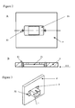
- Figure 2 shows a panel or wall with a perforation provided according to the invention.
- Figure 3 shows a perspective view of a panel mounting adapter fixed to a panel or wall according to the invention.
- Figure 4 shows a panel mounting adapter and a protective plate fixed to a panel or wall according to the invention.
- Figure 5 shows a protective external housing of a cable plug assembly according to the invention.
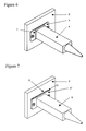
- Figure 6 shows a protected panel connection interface according to a first embodiment of the invention
- Figure 7 shows a protected panel connection interface according to a second embodiment of the invention.
- Figure 1A shows a panel P, panel sides S1 and S2, a panel mounting adapter 2, optical or electrical transmission cables 4, 4', and transmission cable plug assemblies 3, 3'.
- FIG. 1 It shows a top or side view of a conventional panel connection interface in which the panel mounting adapter 2 is fixed to the panel P for reception of plug assemblies 3, 3' of optical or electrical transmission cables 4, 4' on either side S1, S2 of the panel P.
- the optical-to-optical or electrical-to-electrical interface connection may be disconnected and reconnected at any time just by introducing or removing the plug assemblies from the panel mounting adapter 2.
- Figure 1B shows a perspective view of a conventional panel mounting adapter 2 or receptacle which comprises at least a fixing sleeve FS and a coupling body CB.
- Figure 1C shows a top or side view of a conventional optical or electrical transmission cable 4 having a plug assembly 3.
- the plug assembly 3 comprises an optical fiber alignment mechanism, e.g. a ferrule, and for electrical transmission it comprises an electrical alignment mechanism e.g. a male electrical connector.
- Figure 2 shows a panel or wall P, a first perforation P1 and at least one second perforation P2.
- first perforation P1 is provided for receiving a panel mounting adapter (not shown) e. g. of the kind shown in Figure 1 B.
- Said first perforation P1 may be made such that it adapts also to the shape of the panel mounting adapter fixing sleeve, as shown in the figure, but alternatively said first perforation P1 may be adapted just to let the panel mounting adapter coupling body through the panel P, leaving the fixing sleeves outside the panel front surface PFS.
- Further perforations P2 may be provided for fixing a protective plate (not shown) to the panel P according to the invention. These second perforations though are not needed if said protective plate is fixed to the panel or panel mounting adapter by any other means.
- FIG 3 a perspective view of a panel mounting adapter 2 placed in a first perforation of a panel P is shown.
- the panel mounting adapter 2 is fixed to the panel P e.g. by screws or snap-in, and, according to the invention, the space S between the panel mounting adapter 2 and the first perforation is filled with a sealing material, such as a silicone.
- Figure 4 shows a panel P, a panel mounting adapter 2, a protective plate 6 with opening Op and screws 5.
- Figure 4A shows a perspective view of the panel mounting adapter 2 fixed and sealed to the panel P according to the description of Figure 3 and a protective plate 6 fixed to the panel P by means of screws 5, but alternative known fixing means are also possible.
- Figure 4B shows a front view of an exemplary embodiment of a protective plate 6 comprising an opening Op for letting through the panel mounting adapter 2.
- the protective plate 6 is a sheet or foil of material e.g. metal or plastic and, preferably, the opening O has a size bigger than the size of the panel mounting adapter coupling body and adapts to its form.
- the protective plate 6 is sealed to the panel surface by means of a sealing material such as a silicone.
- Figure 5 shows a protective housing 8 and an electrical or optical transmission cable 4.
- the protective housing 8 shown in the figure completely covers the transmission cable plug assembly (not shown), but it is also possible that the protective housing 8 partially covers the transmission cable plug assembly, e.g. an end part of said plug assembly.
- the protective housing 8 may be made of a plastic or elastic material.
- Figure 6 shows a panel P, a protective plate 6 and a protective housing 8 in an assembled state for protection of a panel connection interface according to a first embodiment of the invention.
- the protective plug assembly housing 8 is coupled over the panel mounting adapter (not shown) and in contact with the protective plate 6.
- the plug assembly (not shown) inside the protective housing 8 is inserted inside the panel mounting adapter (not shown) and the form of the protective housing is substantially adapted to the outer form of the panel mounting adapter a certain coupling stability is achieved, and additionally the internal parts of the panel connection interface, that is, the panel mounting adapter and the transmission cable plug assembly, are protected from possible splashing of water or dust particles present in the connection interface application environment.
- the end part of the protective housing 8, that is, the part of the protective housing in contact with the protective plate 6 may comprise projecting lips 7made for example of an elastic material to improve the sealing.
- Figure 7 shows a panel P, a first protective plate 6, a second protective plate 6' and a protective housing 8 in an assembled state for protection of a panel connection interface according to a second embodiment of the invention.
- the protective plug assembly housing 8 is coupled over the panel mounting adapter (not shown) and in contact with the protective plate 6 as already explained in Figure 6.
- a second protective plate 6' is added which, when fixed to the panel P, provides further fixing force to the protective housing 8, by pressing the protective housing projecting lips towards the first protective plate 6, so that coupling stability is improved, and additionally sealing of the internal parts of the panel connection interface is improved.
- the second protective plate 6' may have the same form as the first protective plate 6 but another forms which still achieve the object of the invention are possible.
- the gap G between the first and the second protective plate 6, 6' may be filled with a sealing material or, alternatively the first or second protective plate 6,6' may comprise, at east at the edges, a layer of elastic or foam material which fills that gap G.
- panel connection interface comprising a panel mounting adapter
- said adapter might be replaced by a female electrical connector and the principles of the invention still apply.
- the panel may be an outside wall of a device housing, a wall of a building construction or a support located in such wall.
Landscapes
- Physics & Mathematics (AREA)
- General Physics & Mathematics (AREA)
- Optics & Photonics (AREA)
- Connector Housings Or Holding Contact Members (AREA)
- Coupling Device And Connection With Printed Circuit (AREA)
Abstract
Description
- The present invention relates generally to product protection and more particularly to protection of panel connection interfaces.
- Panel connection interfaces are known as a means to establish an electric or optical transmission connection between two electric or optical transmission elements located at either side of a panel or wall. An example of such panel connection interface, which is considered the closest state of the art, is disclosed in patent application
US 2005/0281510 A1 , in which a fiber optic cable with a plug assembly is engaged to a receptacle provided in a wall. - A problem with such type of connection interfaces, particularly in outdoor environments, is that they are sensible to environmental or application environment effects such as splashing or spray of water and dust. When panel connection interfaces are not protected against such effects the performance and proper function of the electric or optical connection may deteriorate with time.
- It is the object of the present invention to provide protection for panel connection interfaces placed in application environments with the presence of dust and water.
- The object is achieved by a method for protecting a connection interface in a panel or wall according to claim 1 and a protected panel connection interface according to
claim 4. - Further advantageous configurations of the invention emerge from the dependent claims, the following description and the drawings.
- An embodiment example of the invention is now explained with the aid of Figures 1 to 7.
- Figure 1 shows a conventional panel connection interface.
- Figure 2 shows a panel or wall with a perforation provided according to the invention.
- Figure 3 shows a perspective view of a panel mounting adapter fixed to a panel or wall according to the invention.
- Figure 4 shows a panel mounting adapter and a protective plate fixed to a panel or wall according to the invention.
- Figure 5 shows a protective external housing of a cable plug assembly according to the invention.
- Figure 6 shows a protected panel connection interface according to a first embodiment of the invention
- Figure 7 shows a protected panel connection interface according to a second embodiment of the invention.
- Figure 1A shows a panel P, panel sides S1 and S2, a
panel mounting adapter 2, optical orelectrical transmission cables 4, 4', and transmissioncable plug assemblies 3, 3'. - It shows a top or side view of a conventional panel connection interface in which the
panel mounting adapter 2 is fixed to the panel P for reception ofplug assemblies 3, 3' of optical orelectrical transmission cables 4, 4' on either side S1, S2 of the panel P. The optical-to-optical or electrical-to-electrical interface connection may be disconnected and reconnected at any time just by introducing or removing the plug assemblies from thepanel mounting adapter 2. - Figure 1B shows a perspective view of a conventional
panel mounting adapter 2 or receptacle which comprises at least a fixing sleeve FS and a coupling body CB. - Figure 1C shows a top or side view of a conventional optical or
electrical transmission cable 4 having aplug assembly 3. For optical transmission, theplug assembly 3 comprises an optical fiber alignment mechanism, e.g. a ferrule, and for electrical transmission it comprises an electrical alignment mechanism e.g. a male electrical connector. - Figure 2 shows a panel or wall P, a first perforation P1 and at least one second perforation P2.
- It shows a front view of the panel P in which the first perforation P1 is provided for receiving a panel mounting adapter (not shown) e. g. of the kind shown in Figure 1 B. Said first perforation P1 may be made such that it adapts also to the shape of the panel mounting adapter fixing sleeve, as shown in the figure, but alternatively said first perforation P1 may be adapted just to let the panel mounting adapter coupling body through the panel P, leaving the fixing sleeves outside the panel front surface PFS.
- Further perforations P2 may be provided for fixing a protective plate (not shown) to the panel P according to the invention. These second perforations though are not needed if said protective plate is fixed to the panel or panel mounting adapter by any other means.
- In Figure 3 a perspective view of a
panel mounting adapter 2 placed in a first perforation of a panel P is shown. Thepanel mounting adapter 2 is fixed to the panel P e.g. by screws or snap-in, and, according to the invention, the space S between thepanel mounting adapter 2 and the first perforation is filled with a sealing material, such as a silicone. - Figure 4 shows a panel P, a
panel mounting adapter 2, aprotective plate 6 with opening Op andscrews 5. - Figure 4A shows a perspective view of the
panel mounting adapter 2 fixed and sealed to the panel P according to the description of Figure 3 and aprotective plate 6 fixed to the panel P by means ofscrews 5, but alternative known fixing means are also possible. - Figure 4B shows a front view of an exemplary embodiment of a
protective plate 6 comprising an opening Op for letting through thepanel mounting adapter 2. Theprotective plate 6 is a sheet or foil of material e.g. metal or plastic and, preferably, the opening O has a size bigger than the size of the panel mounting adapter coupling body and adapts to its form. Theprotective plate 6 is sealed to the panel surface by means of a sealing material such as a silicone. - Figure 5 shows a
protective housing 8 and an electrical oroptical transmission cable 4. Theprotective housing 8 shown in the figure completely covers the transmission cable plug assembly (not shown), but it is also possible that theprotective housing 8 partially covers the transmission cable plug assembly, e.g. an end part of said plug assembly. Theprotective housing 8 may be made of a plastic or elastic material. - Figure 6 shows a panel P, a
protective plate 6 and aprotective housing 8 in an assembled state for protection of a panel connection interface according to a first embodiment of the invention. The protectiveplug assembly housing 8 is coupled over the panel mounting adapter (not shown) and in contact with theprotective plate 6. - Since the plug assembly (not shown) inside the
protective housing 8 is inserted inside the panel mounting adapter (not shown) and the form of the protective housing is substantially adapted to the outer form of the panel mounting adapter a certain coupling stability is achieved, and additionally the internal parts of the panel connection interface, that is, the panel mounting adapter and the transmission cable plug assembly, are protected from possible splashing of water or dust particles present in the connection interface application environment. - The end part of the
protective housing 8, that is, the part of the protective housing in contact with theprotective plate 6 may comprise projecting lips 7made for example of an elastic material to improve the sealing. - Figure 7 shows a panel P, a first
protective plate 6, a second protective plate 6' and aprotective housing 8 in an assembled state for protection of a panel connection interface according to a second embodiment of the invention. The protectiveplug assembly housing 8 is coupled over the panel mounting adapter (not shown) and in contact with theprotective plate 6 as already explained in Figure 6. - The difference with the protected panel connection interface of Figure 6 is that a second protective plate 6' is added which, when fixed to the panel P, provides further fixing force to the
protective housing 8, by pressing the protective housing projecting lips towards the firstprotective plate 6, so that coupling stability is improved, and additionally sealing of the internal parts of the panel connection interface is improved. The second protective plate 6' may have the same form as the firstprotective plate 6 but another forms which still achieve the object of the invention are possible. - For even more sealing robustness, the gap G between the first and the second
protective plate 6, 6' may be filled with a sealing material or, alternatively the first or secondprotective plate 6,6' may comprise, at east at the edges, a layer of elastic or foam material which fills that gap G. - For the sake of generalization, although the examples of the invention have been directed to panel connection interface comprising a panel mounting adapter it has to be understood that said adapter might be replaced by a female electrical connector and the principles of the invention still apply. It is also understood that the panel may be an outside wall of a device housing, a wall of a building construction or a support located in such wall.
Claims (10)
- Method for protecting a connection interface in a panel or wall (P), the connection interface comprising a panel mounting adapter or connector (2) and at least one plug assembly (3) adapted for coupling with said panel mounting adapter or connector (2), the panel mounting adapter or connector (2) being inserted in a perforation (P1) of the panel (P) and fixed to the panel (P), the method characterized by comprising the steps of:sealing a space (S) left between the panel mounting adapter (2) and said panel (P) and/or perforation (P1) ;providing a first protective plate (6) which completely covers said space (S);sealing the space between said first protective plate (6) and the panel (P) surface;providing a protective housing (8) for the plug assembly (3);coupling the plug assembly with the protective housing (8) with the panel mounting adapter or connector (2) so that the protective housing also covers the panel mounting adapter or connector (2) and so that the protective housing (8) together with the protective plate (6) closes a space comprising the panel mounting adapter or connector (2) and the plug assembly (3).
- The method for protecting a connection interface in a panel or wall (P) according to claim 1 comprising the step of providing a second protective plate (6') over the first protective plate (6).
- The method for protecting a connection interface in a panel or wall (P) according to claim 2 comprising the step of sealing the gap (G) between the first and second protective plates (6, 6').
- The method for protecting a connection interface in a panel or wall (P) according to claim 1 to 3 wherein the first perforation (P1) is made such that the panel mounting adapter or connector (2) fixing sleeves do not do not project outside the panel front surface (PFS).
- Protected panel connection interface in which a panel (P) comprises a perforation (P1) adapted for the reception of a panel mounting adapter (2), which is fixed to said panel (P) such that a certain space (S) is left between the panel mounting adapter (2) and the panel (P) surface or perforation (P1), characterized in that said space (S) is sealed with a sealing material, a protective plate (6) covers said space (S), the space between the protective plate (6) and the panel (P) surface is sealed, and said protective plate (6) together with a protective housing (8) form a closed space covering a plug assembly (3) inserted in the panel mounting adapter (2).
- The protected panel connection interface of claim 5 wherein the protective plate (6) is a sheet of material with an opening (Op) adapted to the form of the panel mounting adapter (2).
- The protected panel connection interface of claim 5 or 6 wherein the part of the protective housing (8) contacting the protective plate (6) comprises projecting lips (7).
- The protected panel connection interface of claims 5 to 7 further comprising a second protective plate (6').
- The protected panel connection interface of claim 8 wherein the first or second protective plate (6, 6') comprises a layer of material which seals the gap (G) between the first and second protective plate (6, 6').
- The protected panel connection interface of claim 7 wherein the gap (G) between the first and second protective plate (6, 6') is sealed with a sealing material.
Priority Applications (4)
| Application Number | Priority Date | Filing Date | Title |
|---|---|---|---|
| AT06290395T ATE395623T1 (en) | 2006-03-07 | 2006-03-07 | PROTECTED BOARD CONNECTION INTERFACE |
| ES06290395T ES2307270T3 (en) | 2006-03-07 | 2006-03-07 | PROTECTED PANEL CONNECTION INTERFACE. |
| EP06290395A EP1832905B1 (en) | 2006-03-07 | 2006-03-07 | Protected panel connection interface |
| DE602006001199T DE602006001199D1 (en) | 2006-03-07 | 2006-03-07 | Protected board connection interface |
Applications Claiming Priority (1)
| Application Number | Priority Date | Filing Date | Title |
|---|---|---|---|
| EP06290395A EP1832905B1 (en) | 2006-03-07 | 2006-03-07 | Protected panel connection interface |
Publications (2)
| Publication Number | Publication Date |
|---|---|
| EP1832905A1 true EP1832905A1 (en) | 2007-09-12 |
| EP1832905B1 EP1832905B1 (en) | 2008-05-14 |
Family
ID=36354112
Family Applications (1)
| Application Number | Title | Priority Date | Filing Date |
|---|---|---|---|
| EP06290395A Expired - Lifetime EP1832905B1 (en) | 2006-03-07 | 2006-03-07 | Protected panel connection interface |
Country Status (4)
| Country | Link |
|---|---|
| EP (1) | EP1832905B1 (en) |
| AT (1) | ATE395623T1 (en) |
| DE (1) | DE602006001199D1 (en) |
| ES (1) | ES2307270T3 (en) |
Cited By (3)
| Publication number | Priority date | Publication date | Assignee | Title |
|---|---|---|---|---|
| CN102308238A (en) * | 2011-07-20 | 2012-01-04 | 华为技术有限公司 | Optical adapter optical port protection component and optical adapter installation box |
| DE102016209448A1 (en) | 2016-05-31 | 2017-11-30 | Zf Friedrichshafen Ag | Radiation protection for housing plug, housing plug and system |
| CN114024166A (en) * | 2021-09-26 | 2022-02-08 | 浙江大华技术股份有限公司 | Cable assembly and method of installing cable assembly |
Citations (3)
| Publication number | Priority date | Publication date | Assignee | Title |
|---|---|---|---|---|
| US5155795A (en) * | 1991-09-23 | 1992-10-13 | G&H Technology, Inc. | Hermetic optical fiber feedthrough arrangement |
| US6445867B1 (en) * | 2000-07-27 | 2002-09-03 | Stratos Lightwave, Inc. | Optical fiber hermetic termination connector |
| US20040062486A1 (en) * | 2002-10-01 | 2004-04-01 | Fujikura Ltd. | Optical connector with shutter |
-
2006
- 2006-03-07 EP EP06290395A patent/EP1832905B1/en not_active Expired - Lifetime
- 2006-03-07 ES ES06290395T patent/ES2307270T3/en not_active Expired - Lifetime
- 2006-03-07 AT AT06290395T patent/ATE395623T1/en not_active IP Right Cessation
- 2006-03-07 DE DE602006001199T patent/DE602006001199D1/en not_active Expired - Lifetime
Patent Citations (3)
| Publication number | Priority date | Publication date | Assignee | Title |
|---|---|---|---|---|
| US5155795A (en) * | 1991-09-23 | 1992-10-13 | G&H Technology, Inc. | Hermetic optical fiber feedthrough arrangement |
| US6445867B1 (en) * | 2000-07-27 | 2002-09-03 | Stratos Lightwave, Inc. | Optical fiber hermetic termination connector |
| US20040062486A1 (en) * | 2002-10-01 | 2004-04-01 | Fujikura Ltd. | Optical connector with shutter |
Cited By (4)
| Publication number | Priority date | Publication date | Assignee | Title |
|---|---|---|---|---|
| CN102308238A (en) * | 2011-07-20 | 2012-01-04 | 华为技术有限公司 | Optical adapter optical port protection component and optical adapter installation box |
| CN102308238B (en) * | 2011-07-20 | 2013-08-14 | 华为技术有限公司 | Optical adapter optical port protection component and optical adapter installation box |
| DE102016209448A1 (en) | 2016-05-31 | 2017-11-30 | Zf Friedrichshafen Ag | Radiation protection for housing plug, housing plug and system |
| CN114024166A (en) * | 2021-09-26 | 2022-02-08 | 浙江大华技术股份有限公司 | Cable assembly and method of installing cable assembly |
Also Published As
| Publication number | Publication date |
|---|---|
| ATE395623T1 (en) | 2008-05-15 |
| EP1832905B1 (en) | 2008-05-14 |
| ES2307270T3 (en) | 2008-11-16 |
| DE602006001199D1 (en) | 2008-06-26 |
Similar Documents
| Publication | Publication Date | Title |
|---|---|---|
| US20220209479A1 (en) | Battery pack with electrical connector mechanism that maintains waterproof integrity of portable electronic device | |
| US8038462B2 (en) | Water-tight electrical connector with laterally compressed O-ring | |
| EP2504728A1 (en) | Outdoor connection for fiber optic transceivers | |
| CN102668263A (en) | push-pull interconnection system | |
| TW559383U (en) | Vertically mated micro coaxal cable connector assembly with grounding shield | |
| EP2418744A1 (en) | Seal device for sealing a connector | |
| CA2857918C (en) | While-in-use outdoor cover with recessed electrical device | |
| CA2645111A1 (en) | Plug arrangement for an electric or optical cable | |
| TWI424806B (en) | Shielding element for an electrical connector module assembly | |
| EP1832905B1 (en) | Protected panel connection interface | |
| JP5369586B2 (en) | Dust-proof structure of modular jack | |
| US9048577B2 (en) | Lever connector with waterproofing | |
| EP1487064A1 (en) | Sealing device for electrical terminals | |
| CN104216054A (en) | Optical fiber adapter | |
| CN112821129B (en) | Backplane Connector Assemblies and Seal Assemblies for Backplane Connectors | |
| CN108206874B (en) | Mobile phone shell | |
| CN108206366B (en) | Waterproof metal shell | |
| US8754331B2 (en) | Strain relief device | |
| JP6015235B2 (en) | Photoelectric composite cable, optical connector cover and connection method | |
| EP4231465A1 (en) | Electronic device and waterproof member thereof | |
| JP2015213206A (en) | communication unit | |
| EP4498844B1 (en) | Aerosol-generating system with connector cover element | |
| CN213584991U (en) | Waterproof mounting structure | |
| WO2018045786A1 (en) | Port for electronic device | |
| JP2010025842A (en) | Gas meter |
Legal Events
| Date | Code | Title | Description |
|---|---|---|---|
| PUAI | Public reference made under article 153(3) epc to a published international application that has entered the european phase |
Free format text: ORIGINAL CODE: 0009012 |
|
| 17P | Request for examination filed |
Effective date: 20060712 |
|
| AK | Designated contracting states |
Kind code of ref document: A1 Designated state(s): AT BE BG CH CY CZ DE DK EE ES FI FR GB GR HU IE IS IT LI LT LU LV MC NL PL PT RO SE SI SK TR |
|
| AX | Request for extension of the european patent |
Extension state: AL BA HR MK YU |
|
| GRAP | Despatch of communication of intention to grant a patent |
Free format text: ORIGINAL CODE: EPIDOSNIGR1 |
|
| GRAS | Grant fee paid |
Free format text: ORIGINAL CODE: EPIDOSNIGR3 |
|
| GRAA | (expected) grant |
Free format text: ORIGINAL CODE: 0009210 |
|
| AK | Designated contracting states |
Kind code of ref document: B1 Designated state(s): AT BE BG CH CY CZ DE DK EE ES FI FR GB GR HU IE IS IT LI LT LU LV MC NL PL PT RO SE SI SK TR |
|
| REG | Reference to a national code |
Ref country code: GB Ref legal event code: FG4D |
|
| AKX | Designation fees paid |
Designated state(s): AT BE BG CH CY CZ DE DK EE ES FI FR GB GR HU IE IS IT LI LT LU LV MC NL PL PT RO SE SI SK TR |
|
| REG | Reference to a national code |
Ref country code: CH Ref legal event code: EP |
|
| REG | Reference to a national code |
Ref country code: IE Ref legal event code: FG4D Free format text: LANGUAGE OF EP DOCUMENT: FRENCH |
|
| REF | Corresponds to: |
Ref document number: 602006001199 Country of ref document: DE Date of ref document: 20080626 Kind code of ref document: P |
|
| REG | Reference to a national code |
Ref country code: CH Ref legal event code: NV Representative=s name: CABINET ROLAND NITHARDT CONSEILS EN PROPRIETE INDU |
|
| PG25 | Lapsed in a contracting state [announced via postgrant information from national office to epo] |
Ref country code: SI Free format text: LAPSE BECAUSE OF FAILURE TO SUBMIT A TRANSLATION OF THE DESCRIPTION OR TO PAY THE FEE WITHIN THE PRESCRIBED TIME-LIMIT Effective date: 20080514 |
|
| PG25 | Lapsed in a contracting state [announced via postgrant information from national office to epo] |
Ref country code: FI Free format text: LAPSE BECAUSE OF FAILURE TO SUBMIT A TRANSLATION OF THE DESCRIPTION OR TO PAY THE FEE WITHIN THE PRESCRIBED TIME-LIMIT Effective date: 20080514 |
|
| NLV1 | Nl: lapsed or annulled due to failure to fulfill the requirements of art. 29p and 29m of the patents act | ||
| REG | Reference to a national code |
Ref country code: ES Ref legal event code: FG2A Ref document number: 2307270 Country of ref document: ES Kind code of ref document: T3 |
|
| PG25 | Lapsed in a contracting state [announced via postgrant information from national office to epo] |
Ref country code: LV Free format text: LAPSE BECAUSE OF FAILURE TO SUBMIT A TRANSLATION OF THE DESCRIPTION OR TO PAY THE FEE WITHIN THE PRESCRIBED TIME-LIMIT Effective date: 20080514 Ref country code: PL Free format text: LAPSE BECAUSE OF FAILURE TO SUBMIT A TRANSLATION OF THE DESCRIPTION OR TO PAY THE FEE WITHIN THE PRESCRIBED TIME-LIMIT Effective date: 20080514 Ref country code: NL Free format text: LAPSE BECAUSE OF FAILURE TO SUBMIT A TRANSLATION OF THE DESCRIPTION OR TO PAY THE FEE WITHIN THE PRESCRIBED TIME-LIMIT Effective date: 20080514 Ref country code: AT Free format text: LAPSE BECAUSE OF FAILURE TO SUBMIT A TRANSLATION OF THE DESCRIPTION OR TO PAY THE FEE WITHIN THE PRESCRIBED TIME-LIMIT Effective date: 20080514 |
|
| PG25 | Lapsed in a contracting state [announced via postgrant information from national office to epo] |
Ref country code: IS Free format text: LAPSE BECAUSE OF FAILURE TO SUBMIT A TRANSLATION OF THE DESCRIPTION OR TO PAY THE FEE WITHIN THE PRESCRIBED TIME-LIMIT Effective date: 20080914 |
|
| PG25 | Lapsed in a contracting state [announced via postgrant information from national office to epo] |
Ref country code: SE Free format text: LAPSE BECAUSE OF FAILURE TO SUBMIT A TRANSLATION OF THE DESCRIPTION OR TO PAY THE FEE WITHIN THE PRESCRIBED TIME-LIMIT Effective date: 20080814 Ref country code: DK Free format text: LAPSE BECAUSE OF FAILURE TO SUBMIT A TRANSLATION OF THE DESCRIPTION OR TO PAY THE FEE WITHIN THE PRESCRIBED TIME-LIMIT Effective date: 20080514 Ref country code: LT Free format text: LAPSE BECAUSE OF FAILURE TO SUBMIT A TRANSLATION OF THE DESCRIPTION OR TO PAY THE FEE WITHIN THE PRESCRIBED TIME-LIMIT Effective date: 20080514 Ref country code: CZ Free format text: LAPSE BECAUSE OF FAILURE TO SUBMIT A TRANSLATION OF THE DESCRIPTION OR TO PAY THE FEE WITHIN THE PRESCRIBED TIME-LIMIT Effective date: 20080514 |
|
| ET | Fr: translation filed | ||
| PG25 | Lapsed in a contracting state [announced via postgrant information from national office to epo] |
Ref country code: SK Free format text: LAPSE BECAUSE OF FAILURE TO SUBMIT A TRANSLATION OF THE DESCRIPTION OR TO PAY THE FEE WITHIN THE PRESCRIBED TIME-LIMIT Effective date: 20080514 Ref country code: RO Free format text: LAPSE BECAUSE OF FAILURE TO SUBMIT A TRANSLATION OF THE DESCRIPTION OR TO PAY THE FEE WITHIN THE PRESCRIBED TIME-LIMIT Effective date: 20080514 Ref country code: BE Free format text: LAPSE BECAUSE OF FAILURE TO SUBMIT A TRANSLATION OF THE DESCRIPTION OR TO PAY THE FEE WITHIN THE PRESCRIBED TIME-LIMIT Effective date: 20080514 Ref country code: PT Free format text: LAPSE BECAUSE OF FAILURE TO SUBMIT A TRANSLATION OF THE DESCRIPTION OR TO PAY THE FEE WITHIN THE PRESCRIBED TIME-LIMIT Effective date: 20081014 |
|
| PLBE | No opposition filed within time limit |
Free format text: ORIGINAL CODE: 0009261 |
|
| STAA | Information on the status of an ep patent application or granted ep patent |
Free format text: STATUS: NO OPPOSITION FILED WITHIN TIME LIMIT |
|
| 26N | No opposition filed |
Effective date: 20090217 |
|
| PG25 | Lapsed in a contracting state [announced via postgrant information from national office to epo] |
Ref country code: EE Free format text: LAPSE BECAUSE OF FAILURE TO SUBMIT A TRANSLATION OF THE DESCRIPTION OR TO PAY THE FEE WITHIN THE PRESCRIBED TIME-LIMIT Effective date: 20080514 Ref country code: BG Free format text: LAPSE BECAUSE OF FAILURE TO SUBMIT A TRANSLATION OF THE DESCRIPTION OR TO PAY THE FEE WITHIN THE PRESCRIBED TIME-LIMIT Effective date: 20080814 |
|
| PG25 | Lapsed in a contracting state [announced via postgrant information from national office to epo] |
Ref country code: MC Free format text: LAPSE BECAUSE OF NON-PAYMENT OF DUE FEES Effective date: 20090331 |
|
| PG25 | Lapsed in a contracting state [announced via postgrant information from national office to epo] |
Ref country code: IE Free format text: LAPSE BECAUSE OF NON-PAYMENT OF DUE FEES Effective date: 20090307 |
|
| PG25 | Lapsed in a contracting state [announced via postgrant information from national office to epo] |
Ref country code: GR Free format text: LAPSE BECAUSE OF FAILURE TO SUBMIT A TRANSLATION OF THE DESCRIPTION OR TO PAY THE FEE WITHIN THE PRESCRIBED TIME-LIMIT Effective date: 20080815 |
|
| PG25 | Lapsed in a contracting state [announced via postgrant information from national office to epo] |
Ref country code: LU Free format text: LAPSE BECAUSE OF NON-PAYMENT OF DUE FEES Effective date: 20090307 |
|
| PG25 | Lapsed in a contracting state [announced via postgrant information from national office to epo] |
Ref country code: HU Free format text: LAPSE BECAUSE OF FAILURE TO SUBMIT A TRANSLATION OF THE DESCRIPTION OR TO PAY THE FEE WITHIN THE PRESCRIBED TIME-LIMIT Effective date: 20081115 |
|
| PG25 | Lapsed in a contracting state [announced via postgrant information from national office to epo] |
Ref country code: TR Free format text: LAPSE BECAUSE OF FAILURE TO SUBMIT A TRANSLATION OF THE DESCRIPTION OR TO PAY THE FEE WITHIN THE PRESCRIBED TIME-LIMIT Effective date: 20080514 |
|
| PG25 | Lapsed in a contracting state [announced via postgrant information from national office to epo] |
Ref country code: CY Free format text: LAPSE BECAUSE OF FAILURE TO SUBMIT A TRANSLATION OF THE DESCRIPTION OR TO PAY THE FEE WITHIN THE PRESCRIBED TIME-LIMIT Effective date: 20080514 |
|
| REG | Reference to a national code |
Ref country code: CH Ref legal event code: PCOW Free format text: ALCATEL LUCENT;3, AVENUE OCTAVE GREARD;75007 PARIS (FR) |
|
| REG | Reference to a national code |
Ref country code: GB Ref legal event code: 732E Free format text: REGISTERED BETWEEN 20130926 AND 20131002 |
|
| REG | Reference to a national code |
Ref country code: FR Ref legal event code: GC Effective date: 20131018 |
|
| REG | Reference to a national code |
Ref country code: FR Ref legal event code: PLFP Year of fee payment: 10 |
|
| REG | Reference to a national code |
Ref country code: FR Ref legal event code: CA Effective date: 20150521 |
|
| REG | Reference to a national code |
Ref country code: FR Ref legal event code: CA Effective date: 20150521 |
|
| REG | Reference to a national code |
Ref country code: FR Ref legal event code: PLFP Year of fee payment: 11 |
|
| REG | Reference to a national code |
Ref country code: FR Ref legal event code: PLFP Year of fee payment: 12 |
|
| PGFP | Annual fee paid to national office [announced via postgrant information from national office to epo] |
Ref country code: DE Payment date: 20170322 Year of fee payment: 12 Ref country code: FR Payment date: 20170322 Year of fee payment: 12 Ref country code: CH Payment date: 20170322 Year of fee payment: 12 |
|
| PGFP | Annual fee paid to national office [announced via postgrant information from national office to epo] |
Ref country code: GB Payment date: 20170322 Year of fee payment: 12 |
|
| PGFP | Annual fee paid to national office [announced via postgrant information from national office to epo] |
Ref country code: ES Payment date: 20170315 Year of fee payment: 12 |
|
| PGFP | Annual fee paid to national office [announced via postgrant information from national office to epo] |
Ref country code: IT Payment date: 20170323 Year of fee payment: 12 |
|
| REG | Reference to a national code |
Ref country code: DE Ref legal event code: R119 Ref document number: 602006001199 Country of ref document: DE |
|
| REG | Reference to a national code |
Ref country code: CH Ref legal event code: PL |
|
| GBPC | Gb: european patent ceased through non-payment of renewal fee |
Effective date: 20180307 |
|
| PG25 | Lapsed in a contracting state [announced via postgrant information from national office to epo] |
Ref country code: DE Free format text: LAPSE BECAUSE OF NON-PAYMENT OF DUE FEES Effective date: 20181002 |
|
| PG25 | Lapsed in a contracting state [announced via postgrant information from national office to epo] |
Ref country code: CH Free format text: LAPSE BECAUSE OF NON-PAYMENT OF DUE FEES Effective date: 20180331 Ref country code: IT Free format text: LAPSE BECAUSE OF NON-PAYMENT OF DUE FEES Effective date: 20180307 Ref country code: GB Free format text: LAPSE BECAUSE OF NON-PAYMENT OF DUE FEES Effective date: 20180307 Ref country code: LI Free format text: LAPSE BECAUSE OF NON-PAYMENT OF DUE FEES Effective date: 20180331 |
|
| PG25 | Lapsed in a contracting state [announced via postgrant information from national office to epo] |
Ref country code: FR Free format text: LAPSE BECAUSE OF NON-PAYMENT OF DUE FEES Effective date: 20180331 |
|
| REG | Reference to a national code |
Ref country code: ES Ref legal event code: FD2A Effective date: 20190904 |
|
| PG25 | Lapsed in a contracting state [announced via postgrant information from national office to epo] |
Ref country code: ES Free format text: LAPSE BECAUSE OF NON-PAYMENT OF DUE FEES Effective date: 20180308 |