EP1832825A2 - Enhanced filter indicator for refrigerator - Google Patents
Enhanced filter indicator for refrigerator Download PDFInfo
- Publication number
- EP1832825A2 EP1832825A2 EP07250912A EP07250912A EP1832825A2 EP 1832825 A2 EP1832825 A2 EP 1832825A2 EP 07250912 A EP07250912 A EP 07250912A EP 07250912 A EP07250912 A EP 07250912A EP 1832825 A2 EP1832825 A2 EP 1832825A2
- Authority
- EP
- European Patent Office
- Prior art keywords
- filter
- filter cartridge
- graphics
- cap
- control
- Prior art date
- Legal status (The legal status is an assumption and is not a legal conclusion. Google has not performed a legal analysis and makes no representation as to the accuracy of the status listed.)
- Withdrawn
Links
Images

Classifications
-
- F—MECHANICAL ENGINEERING; LIGHTING; HEATING; WEAPONS; BLASTING
- F25—REFRIGERATION OR COOLING; COMBINED HEATING AND REFRIGERATION SYSTEMS; HEAT PUMP SYSTEMS; MANUFACTURE OR STORAGE OF ICE; LIQUEFACTION SOLIDIFICATION OF GASES
- F25D—REFRIGERATORS; COLD ROOMS; ICE-BOXES; COOLING OR FREEZING APPARATUS NOT OTHERWISE PROVIDED FOR
- F25D23/00—General constructional features
-
- F—MECHANICAL ENGINEERING; LIGHTING; HEATING; WEAPONS; BLASTING
- F25—REFRIGERATION OR COOLING; COMBINED HEATING AND REFRIGERATION SYSTEMS; HEAT PUMP SYSTEMS; MANUFACTURE OR STORAGE OF ICE; LIQUEFACTION SOLIDIFICATION OF GASES
- F25D—REFRIGERATORS; COLD ROOMS; ICE-BOXES; COOLING OR FREEZING APPARATUS NOT OTHERWISE PROVIDED FOR
- F25D17/00—Arrangements for circulating cooling fluids; Arrangements for circulating gas, e.g. air, within refrigerated spaces
- F25D17/04—Arrangements for circulating cooling fluids; Arrangements for circulating gas, e.g. air, within refrigerated spaces for circulating air, e.g. by convection
- F25D17/042—Air treating means within refrigerated spaces
-
- F—MECHANICAL ENGINEERING; LIGHTING; HEATING; WEAPONS; BLASTING
- F25—REFRIGERATION OR COOLING; COMBINED HEATING AND REFRIGERATION SYSTEMS; HEAT PUMP SYSTEMS; MANUFACTURE OR STORAGE OF ICE; LIQUEFACTION SOLIDIFICATION OF GASES
- F25D—REFRIGERATORS; COLD ROOMS; ICE-BOXES; COOLING OR FREEZING APPARATUS NOT OTHERWISE PROVIDED FOR
- F25D23/00—General constructional features
- F25D23/12—Arrangements of compartments additional to cooling compartments; Combinations of refrigerators with other equipment, e.g. stove
- F25D23/126—Water cooler
-
- F—MECHANICAL ENGINEERING; LIGHTING; HEATING; WEAPONS; BLASTING
- F25—REFRIGERATION OR COOLING; COMBINED HEATING AND REFRIGERATION SYSTEMS; HEAT PUMP SYSTEMS; MANUFACTURE OR STORAGE OF ICE; LIQUEFACTION SOLIDIFICATION OF GASES
- F25D—REFRIGERATORS; COLD ROOMS; ICE-BOXES; COOLING OR FREEZING APPARATUS NOT OTHERWISE PROVIDED FOR
- F25D25/00—Charging, supporting, and discharging the articles to be cooled
-
- F—MECHANICAL ENGINEERING; LIGHTING; HEATING; WEAPONS; BLASTING
- F25—REFRIGERATION OR COOLING; COMBINED HEATING AND REFRIGERATION SYSTEMS; HEAT PUMP SYSTEMS; MANUFACTURE OR STORAGE OF ICE; LIQUEFACTION SOLIDIFICATION OF GASES
- F25D—REFRIGERATORS; COLD ROOMS; ICE-BOXES; COOLING OR FREEZING APPARATUS NOT OTHERWISE PROVIDED FOR
- F25D2323/00—General constructional features not provided for in other groups of this subclass
- F25D2323/121—General constructional features not provided for in other groups of this subclass the refrigerator is characterised by a water filter for the water/ice dispenser
-
- F—MECHANICAL ENGINEERING; LIGHTING; HEATING; WEAPONS; BLASTING
- F25—REFRIGERATION OR COOLING; COMBINED HEATING AND REFRIGERATION SYSTEMS; HEAT PUMP SYSTEMS; MANUFACTURE OR STORAGE OF ICE; LIQUEFACTION SOLIDIFICATION OF GASES
- F25D—REFRIGERATORS; COLD ROOMS; ICE-BOXES; COOLING OR FREEZING APPARATUS NOT OTHERWISE PROVIDED FOR
- F25D2400/00—General features of, or devices for refrigerators, cold rooms, ice-boxes, or for cooling or freezing apparatus not covered by any other subclass
- F25D2400/36—Visual displays
Definitions
- the present invention relates generally to a filter indicator for a refrigerator.
- Filters such as water filters, are commonly used on refrigerator/freezer products to remind consumers to order or replace the filter.
- An electronic display may be located on the control box or door of the refrigerator.
- the indicator can be a series of colored LEDs. Graphics displayed to the side of the LEDs instruct the user on what needs to be done.
- An indicator of this type is disclosed in U.S. Patent No. 6,613,036 .
- Another type of indicator is a two digit seven segment display. The display shows the percent of life remaining for the filter. When the display reaches zero, the user is supposed to replace the filter. The user does not associate the indicator with the filter and the placement of the filter is usually distant from the location of the display, and the user may not be familiar with the placement of the filter, and oftentimes ignores the replacement indicator. Controls located on the control box or door are commonly associated with temperature adjustment, so the user does not associate the indicator with the filter, or its need for replacement.
- the graphic instructions are unhighlighted text that is easy to ignore.
- Some filters are provided with illuminated indicators at or near the filter location, such as those disclosed in U.S. Patents 3,794,168 , 5,128,034 and 6,214,239 , however these indicators are limited to one or more LEDs which provide only a color indicator to the user, and provide a visual indication that is very small in size and easy to overlook or misunderstand.
- filter indicators that may provide an indication to the user that the condition of the filter has changed including color changing indicators, such as disclosed in U.S. Patent Nos. 6,346,143 , 6,497,756 and 6,610,198 , or with indicators that change position, such as disclosed in U.S. Patent No. 4,818,385 .
- Some non-illuminated filter indicators use a change in color of a treated area which is configured to spell out a specific instruction to the user, such as disclosed in U.S. Patent No. 4,336,038 and U.S. Patent Application Publication US2004/0083896 .
- the lack of illumination of these indicators may reduce the likelihood that the indicator is actually observed by the user.
- the present invention in an embodiment, provides an indicator for a refrigerator filter which has a body configured to contain a replaceable filter cartridge and including an openable cap to enclose the filter cartridge within the body.
- the indicator includes a control having a filter life determination mechanism and arranged to emit a signal when a life of the filter cartridge is determined to be expired.
- a visual display is arranged in association with the body which comprises an illuminating component which illuminates upon receipt of the signal from the control, graphics positioned in association with the body, and a light pipe extending from the graphics towards the illuminating component to transmit light from the illuminating component to the graphics.
- the illuminating component comprises an LED.
- the graphics comprise a written instruction to a user to replace the filter cartridge.
- the cap is a co-injected molded plastic part, with one plastic material being light transmissive.
- the indicator includes a second visual display operated by the control providing a user with an indication of the remaining life of the filter cartridge.
- control includes an electronics mechanism for determining a remaining life for the filter cartridge.
- the visual display is powered by a battery.
- control is located on the body.
- the filter cartridge is a water filter.
- the filter cartridge is an air filter.
- the present invention in an embodiment, provides an indicator for a refrigerator filter having a body configured to contain a replaceable filter cartridge and including a removable cap to enclose the filter cartridge within the body.
- the indicator includes a control having a filter life determination mechanism which is arranged to emit a signal when a life of the filter cartridge is determined to be expired.
- the indicator further has a visual display arranged on the body, an LED mounted on the body which is illuminated upon receipt of the signal from the control and a light pipe extending from the cap towards the LED to transmit light from the LED to an exterior surface of the cap, and graphics arranged on the cap illuminated by the illuminating component via the light pipe which graphics are visible from the exterior surface of the cap.
- the cap comprises a pair of co-injected molded plastic parts, with the light pipe being one of the plastic parts being co-injected and an opaque plastic part being another of the plastic parts being co-injected.
- the present invention in an embodiment, provides a refrigerator including a filter indicator including a cabinet and a body mounted in the cabinet configured to contain a replaceable filter cartridge and including an openable cap to enclose the filter cartridge within the body.
- the refrigerator further includes a control having a filter life determination mechanism which is arranged to emit a signal when a life of the filter cartridge is determined to be expired and a visual display associated with the body which comprises an illuminating component which illuminates upon receipt of the signal from the control, graphics positioned in association with the body, and a light pipe extending from the graphics towards the illuminating component to transmit light from the illuminating component to the graphics.
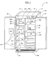
- FIG. 1 is a front perspective view of a refrigerator cabinet, with the doors opened for clarity.
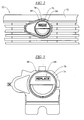
- FIG. 2 is an enlarged elevational view of one of the filters in the cabinet as shown in FIG. 1.
- FIG. 3 is a front elevational view of the filter of FIG. 2.
- FIG. 4 is a schematic side sectional view of the water filter of FIG. 2.
- FIG. 5 is a side sectional view of the air filter of FIG. 1.
- a refrigerator 10 comprising a side-by-side fresh food/freezer configuration, is provided having a cabinet 12 forming fresh food compartment 14 and freezer compartment 16.
- the fresh food compartment 14 is provided with an access opening 18 and a fresh food door 20 hingedly mounted to the cabinet 12 for selectively closing the access opening 18.
- the access opening 18 has a back wall 18a, side walls 18b and 18c, top wall 18d, and a bottom wall 18e.
- the refrigerator 10 also has a partial front wall 22 disposed around the perimeter of the access opening 18 parallel to and selectively engageable with the fresh food door 20 for sealing the access opening 18.
- the fresh food compartment 14 is further provided with a light 24 which is connected in series with a light switch 26.
- the light switch 26 is a reciprocable switch actuated to selectively connect the light 24 with a source of electrical power, not shown, when the door 20 is in an open position and to disconnect the light 24 from the source of electrical power when the fresh food door 20 is in the closed position.
- the light switch is located in portion of the partial front wall 22 above the top wall 18d of the access opening.
- the freezer compartment 16 is provided with an access opening 28 and a freezer door 30 hingedly mounted to the cabinet 12 for selectively closing the access opening 28.
- the access opening 28 has a back wall 28a, side walls 28b and 28c, top wall 28d, and a bottom wall 28e.
- the refrigerator 10 also has a partial front wall 32 disposed around the perimeter of the access opening 28 parallel to and selectively engageable with the freezer door 30 for sealing the access opening 28.
- the freezer compartment 14 is further provided with a light 34 which is connected in series with a light switch 36 functionally similar to the light 24 and light switch 36 in the fresh food compartment 14.
- the refrigerator 10 is provided with a water and ice supply system 40 for delivering water from an external source through a water filter 44 mounted in the cabinet 12 to an ice and water delivery system 46.
- the refrigerator may also, or alternatively be provided with an air circulating system in which an air filter 45 mounted in the cabinet is arranged to remove undesired particulates from an air stream directed through the filter.
- the water filter 44 may be mounted to the refrigerator cabinet 12 below the bottom wall 28e of the access opening 28 and accessed for servicing by selective removal through an opening 47 through the lowermost portion of the partial front wall 32.
- the ice and water delivery system 46 may include an ice making assembly 48 mounted within the freezer compartment 16 and an ice and water dispensing system mounted in the freezer door 30. In some refrigerators, only a water dispensing system may be provided, while in other refrigerators, only an ice dispensing system may be provided.
- a refrigerator control console 60 is defined on an upper portion of the partial front wall 22 of the fresh food compartment 16 in the vicinity of the light switch 26.
- the refrigerator control console 60 which is shown integral with the front wall 22, includes a fresh food compartment temperature control switch 62, a freezer compartment temperature control switch 64, the light switch 26.
- the refrigerator control console 60 may include a filtration system status indicator 66, described below.
- one embodiment of the water filter 44 comprises a body or housing 70 mounted in the cabinet 12 configured to contain a replaceable filter cartridge 72 and including an openable cap 74 to enclose the filter cartridge within the body.
- the filter cartridge 72 may comprise any type of filter medium designed to remove undesired contaminant particles from the fluid passing through the filter cartridge.
- the filter cartridge 72 may be a simple filter material insertable into the body 70 or may include various passages, seals, filter materials, housing elements and other structures that are removed and replaced each time the filter cartridge is changed.
- the cap 74 may be completely removable from the remainder of the body 70, or it may remain attached to the remainder of the body when in the open position. If completely removable, the cap 74 may attach to the remainder of the body 70 such as with a bayonet mount, a threaded connection, a snap or detent connection, or other attachment arrangements. In arrangements where the cap 74 is not removable, it may hinge or pivot to an open position relative to the remainder of the body 70.
- a control 76 which has a filter life determination mechanism 78, for example, such as that disclosed in U.S. Patent No. 6,613,236 , the disclosure of which is incorporated herein by reference.
- the filter life determination mechanism 78 may calculate a remaining life for the filter cartridge 72 based upon time in service, volume of flow of fluid through the filter cartridge, or a combination of these approaches.
- the control 76 is arranged to emit a signal when a life of the filter cartridge is determined to be expired. This signal may be transmitted through a wire 80 or other conductive arrangement, or by a wireless transmission arrangement.
- An illuminating component 82 such as an LED, an incandescent bulb or similar illuminating device, is provided in association with the body 70 and illuminates upon receipt of the signal from the control 76 as part of an indicator 83 for the refrigerator filter 44.
- the illuminating component 82 may be mounted directly on the body 70 or may be located remote from the body.
- a light pipe 84 which may be any arrangement for transmitting light from the illuminating component 82, extends from the cap 74 towards the illuminating component 82 to transmit light from the illuminating component to an exterior surface 86 of the cap.
- the light pipe 84 may be a transparent or translucent plastic or glass material which is configured to allow the illumination from the illuminating component 82 to be directed to a particular location on the cap 74 through a path which is straight or other than a straight line.
- the light pipe 84 may merely be a passage for the light to travel from the illuminating component 82 to the cap 74 without bending or changing direction.
- the cap 74 includes graphics 88 at the outer surface 86 that are illuminated by the illuminating component 82 via the light pipe 84 and are visible from the exterior surface 86 of the cap 74.
- the graphics 88 may comprise a written instruction to a user to replace the filter cartridge 72, such as the word "REPLACE.”
- the graphics 88 may also comprise a picture, icon or symbol indicating to the user that the filter cartridge 72 should be replaced.
- the graphics 88 may be located adjacent to the body 70 rather than being located directly on the cap 74 in some arrangements, but the graphics should be located in close association with the filter 44 so that the user's attention is directed to the location of the filter when the graphics are illuminated.
- graphics is meant to mean something other than the illumination source itself.
- the illumination from the illuminating component 82 may be directed to an outer surface of the graphics 88, or the graphics may be light transmissive so that the illumination can be directed to a back side of the graphics, and transmitted therethrough to the exterior surface 86 of the cap 74.
- the cap may comprise a pair of co-injected molded plastic parts 90, 92, with the light pipe 84 being a light transmissive one of the plastic parts being co-injected and an opaque plastic part being another of the plastic parts being co-injected.
- the control 76 may be mounted remotely from the filter 44, such as at the control console 60, or the control may be mounted directly on the filter body 70.
- the control 76 includes an electronics mechanism for determining a remaining life for the filter cartridge.
- the control 76 and the illuminating component 82 may be powered by a domestic AC power supply 94, such as that used to power the refrigerator 10, or the control or the illuminating component may be powered by a battery to avoid the necessity of running power lines to these components.
- the indicator 83 includes a second visual display, such as the filtration system status indicator 66 mentioned above, which may also be operated by the control 76 providing a user with an indication of the remaining life of the filter cartridge.
- the status indicator 66 may show a percentage of life remaining for the filter 44, or may show an approximate amount of time remaining in the useful life of the filter.
- the user would be provided with an advance warning by the status indicator 66, and a notice to immediately change the filter by the illumination at the outer surface of the body, such as by the illumination of the graphics 88.
- FIG. 5 Another embodiment of the invention is illustrated in FIG. 5, in which the air filter 45 communicates with the air inside of the fresh food compartment 14 and/or the freezer compartment 16.
- the filter 45 comprises a body or housing 100 mounted in the cabinet 12 configured to contain a replaceable filter cartridge 102 and including an openable cap 104 to enclose the filter cartridge within the body.
- the filter cartridge 102 may comprise any type of filter medium designed to remove undesired contaminant particles from the fluid passing through the filter cartridge.
- An air moving device 105 such as a fan, may be used to direct an air stream through the filter cartridge 102, or the air may flow through the filter through natural convection currents.
- the filter cartridge 102 may be a simple filter material insertable into the body 100 or may include various passages, seals, filter materials, housing elements and other structures that are removed and replaced each time the filter cartridge is changed.
- the cap 104 may be completely removable from the remainder of the body 100, or it may remain attached to the remainder of the body when in the open position. If completely removable, the cap 104 may attach to the remainder of the body 100 such as with a bayonet mount, a threaded connection, a snap or detent connection, or other attachment arrangements. In arrangements where the cap 104 is not removable, it may hinge or pivot to an open position relative to the remainder of the body 100.
- a control 106 which has a filter life determination mechanism 108, for example, such as that disclosed in U.S. Patent No. 6,613,236 , the disclosure of which is incorporated herein by reference.
- the filter life determination mechanism 108 may calculate a remaining life for the filter cartridge 102 based upon time in service, volume of flow of fluid through the filter cartridge, or a combination of these approaches.
- the control 106 is arranged to emit a signal when a life of the filter cartridge 102 is determined to be expired. This signal may be transmitted through a wire 110 or other conductive arrangement, or by a wireless transmission arrangement.
- An illuminating component 112 such as an LED, an incandescent bulb or similar illuminating device, may be mounted on or near the body 100 and illuminates upon receipt of the signal from the control 106 as part of an indicator 113 for the refrigerator air filter 45.
- the illuminating component 112 may be mounted directly on the body 100 or may be located remote from the body, such as above the body, and secured directly to the refrigerator as shown in FIG. 5.
- a light pipe 114 which may be any arrangement for transmitting light from the illuminating component 112, extends from the cap 104 towards the illuminating component 112 to transmit light from the illuminating component to an exterior surface 116 of the cap.
- the light pipe 114 may be a transparent or translucent plastic or glass material which is configured to allow the illumination from the illuminating component 112 to be directed to a particular location on the cap 104 through a path which is straight or other than a straight line. In other embodiments, the light pipe 114 may merely be a passage for the light to travel from the illuminating component 112 to the cap 104 without bending or changing direction.
- the cap 104 includes graphics 118 at the outer surface 116 that are illuminated by the illuminating component 112 via the light pipe 114 and are visible from the exterior surface 116 of the cap 104.
- the graphics 118 may comprise a written instruction to a user to replace the filter cartridge 102, such as the word "REPLACE.”
- the graphics 118 may also comprise a picture, icon or symbol indicating to the user that the filter cartridge 102 should be replaced.
- the graphics 118 may be located adjacent to the body 100 rather than being located directly on the cap 104 in some arrangements, but the graphics should be located in close association with the filter 45 so that the user's attention is directed to the location of the filter when the graphics are illuminated.
- graphics is meant to mean something other than the illumination source itself.
- the illumination from the illuminating component 112 may be directed to an outer surface of the graphics 118, or the graphics may be light transmissive so that the illumination can be directed to a back side of the graphics, and transmitted therethrough to the exterior surface 116 of the cap 104.
- the cap 104 may comprise a pair of co-injected molded plastic parts 120, 122, with the light pipe 114 being a light transmissive one of the plastic parts being co-injected and an opaque plastic part being another of the plastic parts being co-injected.
- the control 106 may be mounted remotely from the filter 45, such as at the control console 60, or the control may be mounted directly on the filter body 100.
- the control 106 includes an electronics mechanism for determining a remaining life for the filter cartridge.
- the control 106 and the illuminating component 112 may be powered by a domestic AC power supply, such as that used to power the refrigerator 10, or the control or the illuminating component may be powered by a battery 124 to avoid the necessity of running power lines to these components.
Landscapes
- Engineering & Computer Science (AREA)
- Chemical & Material Sciences (AREA)
- Combustion & Propulsion (AREA)
- Physics & Mathematics (AREA)
- Mechanical Engineering (AREA)
- Thermal Sciences (AREA)
- General Engineering & Computer Science (AREA)
- Cold Air Circulating Systems And Constructional Details In Refrigerators (AREA)
- Devices That Are Associated With Refrigeration Equipment (AREA)
Abstract
An indicator for a refrigerator filter (44,45) which has a body configured to contain a replaceable filter cartridge (72,102) and including an openable cap (74,104) to enclose the filter cartridge within the body. The indicator includes a control having a filter life determination mechanism and arranged to emit a signal when a life of the filter cartridge is determined to be expired. A visual display is arranged in association with the body which comprises an illuminating component (82,112) which illuminates upon receipt of the signal from the control, graphics positioned in association with the body, and a light pipe (84,114) extending from the graphics towards the illuminating component to transmit light from the illuminating component to the graphics.
Description
- The present invention relates generally to a filter indicator for a refrigerator.
- Filters, such as water filters, are commonly used on refrigerator/freezer products to remind consumers to order or replace the filter. An electronic display may be located on the control box or door of the refrigerator. The indicator can be a series of colored LEDs. Graphics displayed to the side of the LEDs instruct the user on what needs to be done. An indicator of this type is disclosed in
U.S. Patent No. 6,613,036 . Another type of indicator is a two digit seven segment display. The display shows the percent of life remaining for the filter. When the display reaches zero, the user is supposed to replace the filter. The user does not associate the indicator with the filter and the placement of the filter is usually distant from the location of the display, and the user may not be familiar with the placement of the filter, and oftentimes ignores the replacement indicator. Controls located on the control box or door are commonly associated with temperature adjustment, so the user does not associate the indicator with the filter, or its need for replacement. The graphic instructions are unhighlighted text that is easy to ignore. - Some filters are provided with illuminated indicators at or near the filter location, such as those disclosed in
U.S. Patents 3,794,168 ,5,128,034 and6,214,239 , however these indicators are limited to one or more LEDs which provide only a color indicator to the user, and provide a visual indication that is very small in size and easy to overlook or misunderstand. - There are other, non-illuminated, filter indicators that may provide an indication to the user that the condition of the filter has changed including color changing indicators, such as disclosed in
U.S. Patent Nos. 6,346,143 ,6,497,756 and6,610,198 , or with indicators that change position, such as disclosed inU.S. Patent No. 4,818,385 . Some non-illuminated filter indicators use a change in color of a treated area which is configured to spell out a specific instruction to the user, such as disclosed inU.S. Patent No. 4,336,038 and U.S. Patent Application PublicationUS2004/0083896 . The lack of illumination of these indicators may reduce the likelihood that the indicator is actually observed by the user. - It would be an improvement in the art if an illuminated indicator were provided for a refrigerator filter that would provide, at or near the location of the filter, a highly visible and instructive indication to the user that the filter required replacement. If the user were provided with a more intuitive indicator, and one that is located at or near the filter location, replacement rates may be improved, resulting in an improved operation of the refrigerator.
- The present invention, in an embodiment, provides an indicator for a refrigerator filter which has a body configured to contain a replaceable filter cartridge and including an openable cap to enclose the filter cartridge within the body. The indicator includes a control having a filter life determination mechanism and arranged to emit a signal when a life of the filter cartridge is determined to be expired. A visual display is arranged in association with the body which comprises an illuminating component which illuminates upon receipt of the signal from the control, graphics positioned in association with the body, and a light pipe extending from the graphics towards the illuminating component to transmit light from the illuminating component to the graphics.
- In an embodiment, the illuminating component comprises an LED.
- In an embodiment, the graphics comprise a written instruction to a user to replace the filter cartridge.
- In an embodiment, the cap is a co-injected molded plastic part, with one plastic material being light transmissive.
- In an embodiment, the indicator includes a second visual display operated by the control providing a user with an indication of the remaining life of the filter cartridge.
- In an embodiment, the control includes an electronics mechanism for determining a remaining life for the filter cartridge.
- In an embodiment, the visual display is powered by a battery.
- In an embodiment, the control is located on the body.
- In an embodiment, the filter cartridge is a water filter.
- In an embodiment, the filter cartridge is an air filter.
- The present invention, in an embodiment, provides an indicator for a refrigerator filter having a body configured to contain a replaceable filter cartridge and including a removable cap to enclose the filter cartridge within the body. The indicator includes a control having a filter life determination mechanism which is arranged to emit a signal when a life of the filter cartridge is determined to be expired. The indicator further has a visual display arranged on the body, an LED mounted on the body which is illuminated upon receipt of the signal from the control and a light pipe extending from the cap towards the LED to transmit light from the LED to an exterior surface of the cap, and graphics arranged on the cap illuminated by the illuminating component via the light pipe which graphics are visible from the exterior surface of the cap. The cap comprises a pair of co-injected molded plastic parts, with the light pipe being one of the plastic parts being co-injected and an opaque plastic part being another of the plastic parts being co-injected.
- The present invention, in an embodiment, provides a refrigerator including a filter indicator including a cabinet and a body mounted in the cabinet configured to contain a replaceable filter cartridge and including an openable cap to enclose the filter cartridge within the body. The refrigerator further includes a control having a filter life determination mechanism which is arranged to emit a signal when a life of the filter cartridge is determined to be expired and a visual display associated with the body which comprises an illuminating component which illuminates upon receipt of the signal from the control, graphics positioned in association with the body, and a light pipe extending from the graphics towards the illuminating component to transmit light from the illuminating component to the graphics.
- The present invention will be further described by way of example with reference to the accompanying drawings, in which:-
- FIG. 1 is a front perspective view of a refrigerator cabinet, with the doors opened for clarity.
- FIG. 2 is an enlarged elevational view of one of the filters in the cabinet as shown in FIG. 1.
- FIG. 3 is a front elevational view of the filter of FIG. 2.
- FIG. 4 is a schematic side sectional view of the water filter of FIG. 2.
- FIG. 5 is a side sectional view of the air filter of FIG. 1.
- In the illustrative embodiment of the invention as shown in FIG. 1, a
refrigerator 10, comprising a side-by-side fresh food/freezer configuration, is provided having acabinet 12 formingfresh food compartment 14 andfreezer compartment 16. - The
fresh food compartment 14 is provided with an access opening 18 and afresh food door 20 hingedly mounted to thecabinet 12 for selectively closing the access opening 18. The access opening 18 has aback wall 18a,side walls top wall 18d, and abottom wall 18e. Therefrigerator 10 also has apartial front wall 22 disposed around the perimeter of the access opening 18 parallel to and selectively engageable with thefresh food door 20 for sealing the access opening 18. - The
fresh food compartment 14 is further provided with alight 24 which is connected in series with alight switch 26. Thelight switch 26 is a reciprocable switch actuated to selectively connect thelight 24 with a source of electrical power, not shown, when thedoor 20 is in an open position and to disconnect thelight 24 from the source of electrical power when thefresh food door 20 is in the closed position. In the preferred embodiment, the light switch is located in portion of thepartial front wall 22 above thetop wall 18d of the access opening. - Similarly, the
freezer compartment 16 is provided with an access opening 28 and afreezer door 30 hingedly mounted to thecabinet 12 for selectively closing the access opening 28. The access opening 28 has aback wall 28a,side walls top wall 28d, and abottom wall 28e. Therefrigerator 10 also has apartial front wall 32 disposed around the perimeter of the access opening 28 parallel to and selectively engageable with thefreezer door 30 for sealing the access opening 28. Thefreezer compartment 14 is further provided with alight 34 which is connected in series with alight switch 36 functionally similar to thelight 24 andlight switch 36 in thefresh food compartment 14. - As is further well known in the art, the
refrigerator 10 is provided with a water andice supply system 40 for delivering water from an external source through awater filter 44 mounted in thecabinet 12 to an ice andwater delivery system 46. The refrigerator may also, or alternatively be provided with an air circulating system in which anair filter 45 mounted in the cabinet is arranged to remove undesired particulates from an air stream directed through the filter. - As shown in FIG. 1, and in greater detail in FIG. 2, the
water filter 44 may be mounted to therefrigerator cabinet 12 below thebottom wall 28e of the access opening 28 and accessed for servicing by selective removal through an opening 47 through the lowermost portion of thepartial front wall 32. - The ice and
water delivery system 46 may include anice making assembly 48 mounted within thefreezer compartment 16 and an ice and water dispensing system mounted in thefreezer door 30. In some refrigerators, only a water dispensing system may be provided, while in other refrigerators, only an ice dispensing system may be provided. - In an embodiment of the present invention, a
refrigerator control console 60 is defined on an upper portion of thepartial front wall 22 of thefresh food compartment 16 in the vicinity of thelight switch 26. Therefrigerator control console 60, which is shown integral with thefront wall 22, includes a fresh food compartment temperature control switch 62, a freezer compartment temperature control switch 64, thelight switch 26. In the vicinity of thelight switch 26, therefrigerator control console 60 may include a filtrationsystem status indicator 66, described below. - As illustrated in FIGs. 2-4, one embodiment of the
water filter 44 comprises a body orhousing 70 mounted in thecabinet 12 configured to contain areplaceable filter cartridge 72 and including anopenable cap 74 to enclose the filter cartridge within the body. Thefilter cartridge 72 may comprise any type of filter medium designed to remove undesired contaminant particles from the fluid passing through the filter cartridge. Thefilter cartridge 72 may be a simple filter material insertable into thebody 70 or may include various passages, seals, filter materials, housing elements and other structures that are removed and replaced each time the filter cartridge is changed. - The
cap 74 may be completely removable from the remainder of thebody 70, or it may remain attached to the remainder of the body when in the open position. If completely removable, thecap 74 may attach to the remainder of thebody 70 such as with a bayonet mount, a threaded connection, a snap or detent connection, or other attachment arrangements. In arrangements where thecap 74 is not removable, it may hinge or pivot to an open position relative to the remainder of thebody 70. - A control 76 is provided which has a filter
life determination mechanism 78, for example, such as that disclosed inU.S. Patent No. 6,613,236 , the disclosure of which is incorporated herein by reference. The filterlife determination mechanism 78 may calculate a remaining life for thefilter cartridge 72 based upon time in service, volume of flow of fluid through the filter cartridge, or a combination of these approaches. The control 76 is arranged to emit a signal when a life of the filter cartridge is determined to be expired. This signal may be transmitted through awire 80 or other conductive arrangement, or by a wireless transmission arrangement. An illuminatingcomponent 82, such as an LED, an incandescent bulb or similar illuminating device, is provided in association with thebody 70 and illuminates upon receipt of the signal from the control 76 as part of anindicator 83 for therefrigerator filter 44. The illuminatingcomponent 82 may be mounted directly on thebody 70 or may be located remote from the body. Alight pipe 84, which may be any arrangement for transmitting light from the illuminatingcomponent 82, extends from thecap 74 towards the illuminatingcomponent 82 to transmit light from the illuminating component to anexterior surface 86 of the cap. Thelight pipe 84 may be a transparent or translucent plastic or glass material which is configured to allow the illumination from the illuminatingcomponent 82 to be directed to a particular location on thecap 74 through a path which is straight or other than a straight line. In other embodiments, thelight pipe 84 may merely be a passage for the light to travel from the illuminatingcomponent 82 to thecap 74 without bending or changing direction. - The
cap 74 includesgraphics 88 at theouter surface 86 that are illuminated by the illuminatingcomponent 82 via thelight pipe 84 and are visible from theexterior surface 86 of thecap 74. For example, thegraphics 88 may comprise a written instruction to a user to replace thefilter cartridge 72, such as the word "REPLACE." Thegraphics 88 may also comprise a picture, icon or symbol indicating to the user that thefilter cartridge 72 should be replaced. Thegraphics 88 may be located adjacent to thebody 70 rather than being located directly on thecap 74 in some arrangements, but the graphics should be located in close association with thefilter 44 so that the user's attention is directed to the location of the filter when the graphics are illuminated. The term graphics, as used herein, is meant to mean something other than the illumination source itself. - The illumination from the illuminating
component 82 may be directed to an outer surface of thegraphics 88, or the graphics may be light transmissive so that the illumination can be directed to a back side of the graphics, and transmitted therethrough to theexterior surface 86 of thecap 74. - In an embodiment, the cap may comprise a pair of co-injected molded
plastic parts light pipe 84 being a light transmissive one of the plastic parts being co-injected and an opaque plastic part being another of the plastic parts being co-injected. - The control 76 may be mounted remotely from the
filter 44, such as at thecontrol console 60, or the control may be mounted directly on thefilter body 70. In an embodiment, the control 76 includes an electronics mechanism for determining a remaining life for the filter cartridge. The control 76 and the illuminatingcomponent 82 may be powered by a domesticAC power supply 94, such as that used to power therefrigerator 10, or the control or the illuminating component may be powered by a battery to avoid the necessity of running power lines to these components. - In an embodiment, the
indicator 83 includes a second visual display, such as the filtrationsystem status indicator 66 mentioned above, which may also be operated by the control 76 providing a user with an indication of the remaining life of the filter cartridge. For example, thestatus indicator 66 may show a percentage of life remaining for thefilter 44, or may show an approximate amount of time remaining in the useful life of the filter. Thus, the user would be provided with an advance warning by thestatus indicator 66, and a notice to immediately change the filter by the illumination at the outer surface of the body, such as by the illumination of thegraphics 88. - Another embodiment of the invention is illustrated in FIG. 5, in which the
air filter 45 communicates with the air inside of thefresh food compartment 14 and/or thefreezer compartment 16. Thefilter 45 comprises a body orhousing 100 mounted in thecabinet 12 configured to contain areplaceable filter cartridge 102 and including anopenable cap 104 to enclose the filter cartridge within the body. Thefilter cartridge 102 may comprise any type of filter medium designed to remove undesired contaminant particles from the fluid passing through the filter cartridge. Anair moving device 105, such as a fan, may be used to direct an air stream through thefilter cartridge 102, or the air may flow through the filter through natural convection currents. Thefilter cartridge 102 may be a simple filter material insertable into thebody 100 or may include various passages, seals, filter materials, housing elements and other structures that are removed and replaced each time the filter cartridge is changed. Thecap 104 may be completely removable from the remainder of thebody 100, or it may remain attached to the remainder of the body when in the open position. If completely removable, thecap 104 may attach to the remainder of thebody 100 such as with a bayonet mount, a threaded connection, a snap or detent connection, or other attachment arrangements. In arrangements where thecap 104 is not removable, it may hinge or pivot to an open position relative to the remainder of thebody 100. - A
control 106 is provided which has a filterlife determination mechanism 108, for example, such as that disclosed inU.S. Patent No. 6,613,236 , the disclosure of which is incorporated herein by reference. The filterlife determination mechanism 108 may calculate a remaining life for thefilter cartridge 102 based upon time in service, volume of flow of fluid through the filter cartridge, or a combination of these approaches. Thecontrol 106 is arranged to emit a signal when a life of thefilter cartridge 102 is determined to be expired. This signal may be transmitted through awire 110 or other conductive arrangement, or by a wireless transmission arrangement. An illuminating component 112, such as an LED, an incandescent bulb or similar illuminating device, may be mounted on or near thebody 100 and illuminates upon receipt of the signal from thecontrol 106 as part of anindicator 113 for therefrigerator air filter 45. The illuminating component 112 may be mounted directly on thebody 100 or may be located remote from the body, such as above the body, and secured directly to the refrigerator as shown in FIG. 5. Alight pipe 114, which may be any arrangement for transmitting light from the illuminating component 112, extends from thecap 104 towards the illuminating component 112 to transmit light from the illuminating component to anexterior surface 116 of the cap. Thelight pipe 114 may be a transparent or translucent plastic or glass material which is configured to allow the illumination from the illuminating component 112 to be directed to a particular location on thecap 104 through a path which is straight or other than a straight line. In other embodiments, thelight pipe 114 may merely be a passage for the light to travel from the illuminating component 112 to thecap 104 without bending or changing direction. - The
cap 104 includesgraphics 118 at theouter surface 116 that are illuminated by the illuminating component 112 via thelight pipe 114 and are visible from theexterior surface 116 of thecap 104. For example, thegraphics 118 may comprise a written instruction to a user to replace thefilter cartridge 102, such as the word "REPLACE." Thegraphics 118 may also comprise a picture, icon or symbol indicating to the user that thefilter cartridge 102 should be replaced. Thegraphics 118 may be located adjacent to thebody 100 rather than being located directly on thecap 104 in some arrangements, but the graphics should be located in close association with thefilter 45 so that the user's attention is directed to the location of the filter when the graphics are illuminated. The term graphics, as used herein, is meant to mean something other than the illumination source itself. - The illumination from the illuminating component 112 may be directed to an outer surface of the
graphics 118, or the graphics may be light transmissive so that the illumination can be directed to a back side of the graphics, and transmitted therethrough to theexterior surface 116 of thecap 104. - In an embodiment, the
cap 104 may comprise a pair of co-injected moldedplastic parts light pipe 114 being a light transmissive one of the plastic parts being co-injected and an opaque plastic part being another of the plastic parts being co-injected. - The
control 106 may be mounted remotely from thefilter 45, such as at thecontrol console 60, or the control may be mounted directly on thefilter body 100. In an embodiment, thecontrol 106 includes an electronics mechanism for determining a remaining life for the filter cartridge. Thecontrol 106 and the illuminating component 112 may be powered by a domestic AC power supply, such as that used to power therefrigerator 10, or the control or the illuminating component may be powered by abattery 124 to avoid the necessity of running power lines to these components. - The present invention has been described utilizing particular embodiments. As will be evident to those skilled in the art, changes and modifications may be made to the disclosed embodiments and yet fall within the scope of the present invention as defined by the attached claims. For example, various components could be utilized separately or independently in some embodiments without using all of the other components in the particular described embodiment. The disclosed embodiment is provided only to illustrate aspects of the present invention whose scope is defined by the appended claims.
Claims (10)
- An indicator for a refrigerator filter comprising:a body configured to contain a replaceable filter cartridge and including an openable cap to enclose the filter cartridge within the body;a control having a filter life determination mechanism and arranged to emit a signal when a life of the filter cartridge is determined to be expired; anda visual display arranged in association with the body which comprises:an illuminating component which illuminates upon receipt of the signal from the control;graphics positioned in association with the body; anda light pipe extending from the graphics towards the illuminating component to transmit light from the illuminating component to the graphics.
- An indicator according to claim 1, wherein the graphics are located on the cap.
- An indicator according to claim 1 or 2, wherein the cap is a co-injected molded plastic part, with one plastic material being light transmissive.
- An indicator according to claim 1, 2 or 3 wherein the indicator includes a second visual display operated by the control providing a user with an indication of the remaining life of the filter cartridge.
- An indicator according to claim 1, 2, 3, or 4 wherein the control includes an electronics mechanism for determining a remaining life for the filter cartridge.
- An indicator for a refrigerator filter comprising:a body configured to contain a replaceable filter cartridge and including a removable cap to enclose the filter cartridge within the body;a control having a filter life determination mechanism and arranged to emit a signal when a life of the filter cartridge is determined to be expired;a visual display arranged on the body; andan LED mounted on the body which is illuminated upon receipt of the signal from the control;a light pipe extending from the cap towards the LED to transmit light from the LED to an exterior surface of the cap; andgraphics arranged on the cap illuminated by the illuminating component via the light pipe which graphics are visible from the exterior surface of the cap;the cap comprising a pair of co-injected molded plastic parts, with the light pipe being one of the plastic parts being co-injected and an opaque plastic part being another of the plastic parts being co-injected.
- A refrigerator including a filter indicator comprising:a cabinet;a body mounted in the cabinet configured to contain a replaceable filter cartridge and including an openable cap to enclose the filter cartridge within the body;a control having a filter life determination mechanism and arranged to emit a signal when a life of the filter cartridge is determined to be expired; anda visual display associated with the body which comprises:an illuminating component which illuminates upon receipt of the signal from the control;graphics positioned in association with the body; anda light pipe extending from the graphics towards the illuminating component to transmit light from the illuminating component to the graphics.
- A refrigerator according to claim 7, wherein the indicator includes a second visual display located in the cabinet remote from the body and operated by the control providing a user with an indication of the remaining life of the filter cartridge.
- A refrigerator according to claim 7 or 8, wherein the visual display is powered by a battery.
- A refrigerator according to claim 7, 8 or 9 wherein the control is located on the body.
Applications Claiming Priority (1)
| Application Number | Priority Date | Filing Date | Title |
|---|---|---|---|
| US11/373,342 US8337693B2 (en) | 2006-03-10 | 2006-03-10 | Enhanced filter indicatior for refrigerator |
Publications (1)
| Publication Number | Publication Date |
|---|---|
| EP1832825A2 true EP1832825A2 (en) | 2007-09-12 |
Family
ID=38193777
Family Applications (1)
| Application Number | Title | Priority Date | Filing Date |
|---|---|---|---|
| EP07250912A Withdrawn EP1832825A2 (en) | 2006-03-10 | 2007-03-06 | Enhanced filter indicator for refrigerator |
Country Status (5)
| Country | Link |
|---|---|
| US (1) | US8337693B2 (en) |
| EP (1) | EP1832825A2 (en) |
| KR (1) | KR20070092658A (en) |
| BR (1) | BRPI0700658A (en) |
| MX (1) | MX2007002840A (en) |
Cited By (2)
| Publication number | Priority date | Publication date | Assignee | Title |
|---|---|---|---|---|
| EP2801773A3 (en) * | 2013-05-07 | 2015-04-08 | Liebherr-Hausgeräte Ochsenhausen GmbH | Refrigeration and/or freezer device |
| EP2492621A3 (en) * | 2011-02-22 | 2017-10-11 | Lg Electronics Inc. | Refrigerator with water purifying means |
Families Citing this family (11)
| Publication number | Priority date | Publication date | Assignee | Title |
|---|---|---|---|---|
| DE102007047118A1 (en) * | 2007-10-02 | 2009-04-09 | BSH Bosch und Siemens Hausgeräte GmbH | Air filter and refrigeration device with an air filter |
| US8656728B2 (en) * | 2010-10-21 | 2014-02-25 | General Electric Company | Water filter with performance indicating device and refrigeration appliance including same |
| US8673136B2 (en) | 2011-06-16 | 2014-03-18 | Whirlpool Corporation | Smart filter |
| KR101822941B1 (en) * | 2012-02-06 | 2018-01-29 | 엘지전자 주식회사 | Air cleaning filter and method for manufacturing the same |
| JP5727562B2 (en) * | 2013-08-30 | 2015-06-03 | ファナック株式会社 | EDM machine filter |
| US9114345B2 (en) | 2014-01-07 | 2015-08-25 | General Electric Company | Low power water filter monitoring system |
| CN107002526B (en) | 2014-11-10 | 2019-07-16 | 康明斯排放处理公司 | Exhaust fluid filter including hydrocarbon detection generating medium and method of detecting hydrocarbons |
| US11273397B2 (en) | 2018-09-13 | 2022-03-15 | Electrolux Home Products, Inc. | Filter base for electronic connection to mating filter housing assembly |
| US10907288B1 (en) | 2019-09-27 | 2021-02-02 | Whirlpool Corporation | Household appliance with luminary communication interface |
| US11413560B2 (en) | 2019-11-18 | 2022-08-16 | Electrolux Home Products, Inc. | Push filter with floating key lock |
| US12551827B2 (en) | 2023-03-01 | 2026-02-17 | Haier Us Appliance Solutions, Inc. | Power and communication delivery configuration for a water filtration assembly of an appliance |
Family Cites Families (19)
| Publication number | Priority date | Publication date | Assignee | Title |
|---|---|---|---|---|
| US2190123A (en) * | 1938-07-02 | 1940-02-13 | Stephen C Pace | Lighting signal |
| US3794168A (en) | 1972-07-31 | 1974-02-26 | Parker Hannifin Corp | Filter with condition indicator |
| DE7809170U1 (en) | 1978-03-25 | 1978-07-27 | Fa. Carl Freudenberg, 6940 Weinheim | FILTER MAT |
| US4818385A (en) | 1987-08-31 | 1989-04-04 | Medley Iii Frank W | Filter with high pressure indicator |
| US5128034A (en) | 1991-03-21 | 1992-07-07 | Amway Corporation | Pressure vessel for housing a water filter |
| US5671996A (en) * | 1994-12-30 | 1997-09-30 | Donnelly Corporation | Vehicle instrumentation/console lighting |
| US6214239B1 (en) | 1996-12-09 | 2001-04-10 | Renau Corporation | Water filter usage monitoring apparatus |
| US6641727B1 (en) * | 1998-03-04 | 2003-11-04 | American Standard International Inc. | Filter faucet |
| US6245229B1 (en) | 1998-07-31 | 2001-06-12 | Amway Corporation | Point-of-use water treatment system |
| US6170956B1 (en) * | 1998-10-14 | 2001-01-09 | Gentex Corporation | Rearview mirror with display |
| US6375834B1 (en) * | 1999-06-30 | 2002-04-23 | Whirlpool Corporation | Water filter monitoring and indicating system |
| US6306290B1 (en) * | 2000-06-26 | 2001-10-23 | Patrick J. Rolfes | Water filter replacement indicator |
| US6497756B1 (en) | 2000-09-12 | 2002-12-24 | North Safety Products, Inc. | Service life indicator for respirator cartridge |
| US6610198B1 (en) | 2001-08-22 | 2003-08-26 | Fleetguard, Inc. | Liquid filter with change interval indicator |
| CN1636424A (en) | 2002-02-19 | 2005-07-06 | 通达商业集团国际公司 | Starter assemblies for gas discharge lamps |
| US6979361B2 (en) | 2002-07-17 | 2005-12-27 | Gueorgui Milev Mihayiov | End of service life indicator for fluid filter |
| WO2004013047A2 (en) * | 2002-08-02 | 2004-02-12 | Eggs In The Pipeline, Llc. | System for adding consumable enhancing additives to drinking water |
| WO2004073135A2 (en) * | 2003-02-10 | 2004-08-26 | Briggs & Stratton Power Products Group, Llc | Monitoring system for a generator |
| US6918259B2 (en) | 2003-07-31 | 2005-07-19 | Troy M. Anderson | Air circulation and filtration system for a refrigerator |
-
2006
- 2006-03-10 US US11/373,342 patent/US8337693B2/en active Active
-
2007
- 2007-03-06 EP EP07250912A patent/EP1832825A2/en not_active Withdrawn
- 2007-03-08 MX MX2007002840A patent/MX2007002840A/en not_active Application Discontinuation
- 2007-03-09 BR BRPI0700658-6A patent/BRPI0700658A/en not_active IP Right Cessation
- 2007-03-09 KR KR1020070023312A patent/KR20070092658A/en not_active Withdrawn
Cited By (2)
| Publication number | Priority date | Publication date | Assignee | Title |
|---|---|---|---|---|
| EP2492621A3 (en) * | 2011-02-22 | 2017-10-11 | Lg Electronics Inc. | Refrigerator with water purifying means |
| EP2801773A3 (en) * | 2013-05-07 | 2015-04-08 | Liebherr-Hausgeräte Ochsenhausen GmbH | Refrigeration and/or freezer device |
Also Published As
| Publication number | Publication date |
|---|---|
| US20070209978A1 (en) | 2007-09-13 |
| BRPI0700658A (en) | 2007-11-06 |
| KR20070092658A (en) | 2007-09-13 |
| US8337693B2 (en) | 2012-12-25 |
| MX2007002840A (en) | 2008-11-14 |
Similar Documents
| Publication | Publication Date | Title |
|---|---|---|
| KR20070092658A (en) | Filter indicator for refrigerator | |
| EP2452139B1 (en) | Liquid dispenser | |
| EP2492621B1 (en) | Refrigerator with water purifying means | |
| EP2245401B1 (en) | Refrigerator | |
| US8613205B2 (en) | Back light in ice storage area | |
| MX2007015313A (en) | Enhanced aesthetics for water dispensing illumination. | |
| CN2578673Y (en) | Lighting spherical lampshade | |
| EP4155632B1 (en) | Ice making machine | |
| US8333084B2 (en) | Refrigerator and lighting device therefor | |
| US9897372B2 (en) | Integrated lighting system for the interior liner of an appliance | |
| KR20010005331A (en) | Filtering apparatus of source direct-connecting and control method thereof. | |
| US20080041073A1 (en) | Water product dispensing system | |
| US20050047143A1 (en) | Single light illumination system for a fluid tap | |
| US20150190745A1 (en) | Low power water filter monitoring system | |
| CN109425196B (en) | Refrigerator with a door | |
| KR200429787Y1 (en) | Water Purifier Faucet Faucets | |
| KR200237689Y1 (en) | Lighting device combine with indicator of a hot and chilled water generator and a elarifier | |
| CN204824429U (en) | Water purification equipment | |
| CN223722874U (en) | Salt box and water softener | |
| CN208704293U (en) | A kind of refrigerator operation plate and refrigerator | |
| KR100867193B1 (en) | Lighting equipment for water purifiers | |
| CN1327178C (en) | Refrigerator | |
| CN101231128B (en) | Illumination mechanism of distributer for refrigerator | |
| JP5114891B2 (en) | Air conditioner | |
| CN2748004Y (en) | Drinking machine with built-in type storage tank |
Legal Events
| Date | Code | Title | Description |
|---|---|---|---|
| PUAI | Public reference made under article 153(3) epc to a published international application that has entered the european phase |
Free format text: ORIGINAL CODE: 0009012 |
|
| AK | Designated contracting states |
Kind code of ref document: A2 Designated state(s): AT BE BG CH CY CZ DE DK EE ES FI FR GB GR HU IE IS IT LI LT LU LV MC MT NL PL PT RO SE SI SK TR |
|
| AX | Request for extension of the european patent |
Extension state: AL BA HR MK YU |
|
| STAA | Information on the status of an ep patent application or granted ep patent |
Free format text: STATUS: THE APPLICATION HAS BEEN WITHDRAWN |
|
| 18W | Application withdrawn |
Effective date: 20140829 |