EP1832779A1 - Electrorheological inertia brake - Google Patents
Electrorheological inertia brake Download PDFInfo
- Publication number
- EP1832779A1 EP1832779A1 EP07102797A EP07102797A EP1832779A1 EP 1832779 A1 EP1832779 A1 EP 1832779A1 EP 07102797 A EP07102797 A EP 07102797A EP 07102797 A EP07102797 A EP 07102797A EP 1832779 A1 EP1832779 A1 EP 1832779A1
- Authority
- EP
- European Patent Office
- Prior art keywords
- electrorheological
- inertia brake
- shaft
- cavity
- housing
- Prior art date
- Legal status (The legal status is an assumption and is not a legal conclusion. Google has not performed a legal analysis and makes no representation as to the accuracy of the status listed.)
- Withdrawn
Links
- 230000005540 biological transmission Effects 0.000 claims abstract description 47
- 239000012530 fluid Substances 0.000 claims abstract description 26
- 239000012212 insulator Substances 0.000 claims description 11
- 230000002708 enhancing effect Effects 0.000 claims 5
- 230000009347 mechanical transmission Effects 0.000 abstract description 12
- 238000000429 assembly Methods 0.000 description 5
- 230000000712 assembly Effects 0.000 description 5
- 239000004020 conductor Substances 0.000 description 3
- 230000033001 locomotion Effects 0.000 description 3
- 230000008859 change Effects 0.000 description 2
- 230000008878 coupling Effects 0.000 description 2
- 238000010168 coupling process Methods 0.000 description 2
- 238000005859 coupling reaction Methods 0.000 description 2
- 229910052751 metal Inorganic materials 0.000 description 2
- 239000002184 metal Substances 0.000 description 2
- 238000000034 method Methods 0.000 description 2
- 238000005240 physical vapour deposition Methods 0.000 description 2
- 239000004033 plastic Substances 0.000 description 2
- 229920003023 plastic Polymers 0.000 description 2
- 230000009467 reduction Effects 0.000 description 2
- RYGMFSIKBFXOCR-UHFFFAOYSA-N Copper Chemical compound [Cu] RYGMFSIKBFXOCR-UHFFFAOYSA-N 0.000 description 1
- 230000005355 Hall effect Effects 0.000 description 1
- 239000004677 Nylon Substances 0.000 description 1
- 229910052782 aluminium Inorganic materials 0.000 description 1
- XAGFODPZIPBFFR-UHFFFAOYSA-N aluminium Chemical compound [Al] XAGFODPZIPBFFR-UHFFFAOYSA-N 0.000 description 1
- 238000002485 combustion reaction Methods 0.000 description 1
- 229910052802 copper Inorganic materials 0.000 description 1
- 239000010949 copper Substances 0.000 description 1
- 230000000694 effects Effects 0.000 description 1
- 239000012777 electrically insulating material Substances 0.000 description 1
- 230000006872 improvement Effects 0.000 description 1
- 239000000314 lubricant Substances 0.000 description 1
- 230000004048 modification Effects 0.000 description 1
- 238000012986 modification Methods 0.000 description 1
- 229920001778 nylon Polymers 0.000 description 1
- 239000004800 polyvinyl chloride Substances 0.000 description 1
- 230000008569 process Effects 0.000 description 1
- 238000004544 sputter deposition Methods 0.000 description 1
- 230000003068 static effect Effects 0.000 description 1
Images


Classifications
-
- F—MECHANICAL ENGINEERING; LIGHTING; HEATING; WEAPONS; BLASTING
- F16—ENGINEERING ELEMENTS AND UNITS; GENERAL MEASURES FOR PRODUCING AND MAINTAINING EFFECTIVE FUNCTIONING OF MACHINES OR INSTALLATIONS; THERMAL INSULATION IN GENERAL
- F16D—COUPLINGS FOR TRANSMITTING ROTATION; CLUTCHES; BRAKES
- F16D57/00—Liquid-resistance brakes; Brakes using the internal friction of fluids or fluid-like media, e.g. powders
- F16D57/002—Liquid-resistance brakes; Brakes using the internal friction of fluids or fluid-like media, e.g. powders comprising a medium with electrically or magnetically controlled internal friction, e.g. electrorheological fluid, magnetic powder
-
- F—MECHANICAL ENGINEERING; LIGHTING; HEATING; WEAPONS; BLASTING
- F16—ENGINEERING ELEMENTS AND UNITS; GENERAL MEASURES FOR PRODUCING AND MAINTAINING EFFECTIVE FUNCTIONING OF MACHINES OR INSTALLATIONS; THERMAL INSULATION IN GENERAL
- F16H—GEARING
- F16H3/00—Toothed gearings for conveying rotary motion with variable gear ratio or for reversing rotary motion
- F16H3/02—Toothed gearings for conveying rotary motion with variable gear ratio or for reversing rotary motion without gears having orbital motion
- F16H3/08—Toothed gearings for conveying rotary motion with variable gear ratio or for reversing rotary motion without gears having orbital motion exclusively or essentially with continuously meshing gears, that can be disengaged from their shafts
- F16H3/087—Toothed gearings for conveying rotary motion with variable gear ratio or for reversing rotary motion without gears having orbital motion exclusively or essentially with continuously meshing gears, that can be disengaged from their shafts characterised by the disposition of the gears
- F16H3/093—Toothed gearings for conveying rotary motion with variable gear ratio or for reversing rotary motion without gears having orbital motion exclusively or essentially with continuously meshing gears, that can be disengaged from their shafts characterised by the disposition of the gears with two or more countershafts
- F16H3/095—Toothed gearings for conveying rotary motion with variable gear ratio or for reversing rotary motion without gears having orbital motion exclusively or essentially with continuously meshing gears, that can be disengaged from their shafts characterised by the disposition of the gears with two or more countershafts with means for ensuring an even distribution of torque between the countershafts
-
- F—MECHANICAL ENGINEERING; LIGHTING; HEATING; WEAPONS; BLASTING
- F16—ENGINEERING ELEMENTS AND UNITS; GENERAL MEASURES FOR PRODUCING AND MAINTAINING EFFECTIVE FUNCTIONING OF MACHINES OR INSTALLATIONS; THERMAL INSULATION IN GENERAL
- F16H—GEARING
- F16H3/00—Toothed gearings for conveying rotary motion with variable gear ratio or for reversing rotary motion
- F16H3/02—Toothed gearings for conveying rotary motion with variable gear ratio or for reversing rotary motion without gears having orbital motion
- F16H3/08—Toothed gearings for conveying rotary motion with variable gear ratio or for reversing rotary motion without gears having orbital motion exclusively or essentially with continuously meshing gears, that can be disengaged from their shafts
- F16H3/12—Toothed gearings for conveying rotary motion with variable gear ratio or for reversing rotary motion without gears having orbital motion exclusively or essentially with continuously meshing gears, that can be disengaged from their shafts with means for synchronisation not incorporated in the clutches
-
- Y—GENERAL TAGGING OF NEW TECHNOLOGICAL DEVELOPMENTS; GENERAL TAGGING OF CROSS-SECTIONAL TECHNOLOGIES SPANNING OVER SEVERAL SECTIONS OF THE IPC; TECHNICAL SUBJECTS COVERED BY FORMER USPC CROSS-REFERENCE ART COLLECTIONS [XRACs] AND DIGESTS
- Y10—TECHNICAL SUBJECTS COVERED BY FORMER USPC
- Y10T—TECHNICAL SUBJECTS COVERED BY FORMER US CLASSIFICATION
- Y10T74/00—Machine element or mechanism
- Y10T74/19—Gearing
- Y10T74/19219—Interchangeably locked
- Y10T74/19284—Meshing assisters
Definitions
- the invention relates generally to inertia brakes and more specifically to an electrorheological inertia brake for a manual or automated mechanical transmission.
- AMTs automated mechanical transmissions
- One such criterion is the desire to accomplish a shift from a first gear ratio to a second gear ratio with an absolute minimum of time during which the master clutch is disengaged and thus the vehicle is without drive energy. Reducing or minimizing master clutch disengagement time during a gear shift improves both actual and perceived vehicle control increasing both vehicle performance and driver satisfaction.
- a tractor trailer may be accelerating up a grade and the transmission controller determines that an upshift is appropriate.
- the clutch is disengaged and the transmission actuators disengage the just utilized gear and attempt to engage the next selected gear.
- the transmission countershaft or countershafts slow the new gear cannot be engaged. If the ramp down of the countershaft and gear speeds is slow, the vehicle may have slowed to the point where the previously commanded upshift is no longer feasible or appropriate.
- the commanded upshift is completed.
- the time consuming gear selection and reengagement of the master clutch may necessitate an immediate downshift due to the speed and that speed lost during the shift.
- vehicle speed and other parameters may continue to drop as the transmission controller repeatedly attempts to select a lower gear (higher numerical reduction) to match the vehicle speed and the vehicle may actually cease forward motion before a gear can be and is successfully selected and engaged. Such behavior on behalf of the transmission and controller is unacceptable.
- the foregoing example highlights the importance of rapid completion of a selected shift, particularly an upshift.
- This operational requirement implicates control of the countershaft or layshaft speeds to rapidly achieve synchronism in the newly selected gear in order to rapidly complete such gear selection and achieve the ultimate goal of minimum time of master clutch disengagement.
- the present invention is directed to achieving such control of the rotational speed of transmission input shafts, layshafts or countershafts.
- An electrorheological inertia brake for a manual transmission or an automated mechanical transmission (AMT) provides improved control of the speed of input shafts, layshafts and countershafts and extends the service life of the transmission.
- the electrorheological inertia brake includes a housing defining a cavity filled with an electrorheological fluid, a shaft coupled to a transmission shaft extends into the cavity and includes blades, vanes, paddles or other drag increasing features.
- An electric current which may be of variable intensity is passed through the fluid to increase the viscosity, create drag and slow the associated transmission components as necessary to achieve synchronism and facilitate rapid shift completions.
- the electrorheological inertia brake provides extended service life relative to conventional inertia brakes since it lacks friction disks which are subject to wear.
- Figure 1 is a diagrammatic view of the powertrain of a typical truck tractor which incorporates the present invention
- Figure 2 is a full, sectional view of a multiple speed ratio heavy duty transmission incorporating an inertia brake according to the present invention.
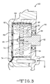
- Figure 3 is an enlarged, full sectional view of an electrorheological inertia brake according to the present invention.
- the truck tractor powertrain assembly 10 includes a primer mover 12 which may be either a gasoline or Diesel internal combustion engine.
- the engine 12 will typically include a turbocharger or supercharger (not illustrated).
- the output of the primer mover 12 is coupled to a master friction clutch 14.
- the master friction clutch 14 may be either manually controlled by the vehicle operator in a mechanical system or under the control of a hydraulic or pneumatic actuator 16 which, in turn, is controlled by an onboard computer or microprocessor 18.
- the output of the master friction clutch 14 is provided to the input of a transmission assembly 20.
- the transmission assembly 20 may be either a mechanical transmission or an automated mechanical transmission (AMT) having a plurality of forward and reverse speeds or gear ratios which may be either selected by the vehicle operator in the case of a manual transmission or selected and controlled by the computer or microprocessor 18 in the case of automated mechanical transmission.
- AMT automated mechanical transmission
- the transmission assembly 20 includes an actuator assembly 22 having a plurality of electric, hydraulic or pneumatic actuators coupled to shift rails and shift forks which effect such gear ratio changes and selections.
- An output shaft 23 of the transmission assembly 20 drives a prop shaft 24 which carries drive torque to a differential 26.
- the prop shaft 24 may include universal joints 25 at both ends to compensate for and permit static and dynamic misalignments between the output shaft 23 of the transmission assembly 20 and the input of the differential 26.
- Rear axles or half shafts 28 extend from the differential 26 and drive rear single or tandem tire and wheel assemblies 30.
- the power train assembly 10 also includes front tire and wheel assemblies 32 which are mounted for rotation and pivotal movement on a front axle 34.
- a steering linkage 36 provides angular or pivotal motion of the front tire and wheel assemblies 32 as commanded by a steering wheel 38.
- the transmission assembly 20 includes an input shaft 40 which is coupled to and driven by the output of the master friction clutch 14 illustrated in Figure 1.
- the input shaft 40 provides drive torque to a first splitter transmission assembly 44 at the left or forward portion of the transmission assembly 20.
- the splitter assembly 44 provides two speed ratios which are utilized in tandem with the other gear and speed ratio changing assemblies of the transmission assembly 20.
- the transmission assembly 20 illustrated includes first and second layshafts or countershafts 42A and 42B upon which are secured and commonly rotate pluralities of gears. It will be appreciated that the invention disclosed herein is equally suitable for a transmission assembly utilizing a single countershaft or layshaft.
- the splitter assembly 44 operates in conjunction with the main transmission assembly 46 which may include three or four forward speeds or gear ratios.
- the illustrated main assembly 46 provides four forward speeds or gear ratios.
- the selection of the gear ratios is achieved by a plurality of dog clutches 48 disposed about and splined to an intermediate output shaft 50.
- the dog clutches 48 are translated fore and aft along the intermediate output shaft 50 by shift forks which are, in turn, translated by a bank of electric, hydraulic or pneumatic actuators contained within the actuator assembly 22 illustrated in Figure 1.
- the intermediate output shaft 50 provides drive torque to a two speed, i.e., two gear ratio, planetary range change group or assembly 52.
- the output of the range change group or assembly 52 is provided to the output shaft or member 23, which may include a flange, suitable internal splines or other coupling feature as desired.
- a speed sensor assembly 54 such as a variable reluctance or Hall effect sensor is disposed at one end of the countershaft 42A and provides data regarding the rotational speed thereof to the computer or microprocessor 18.
- the transmission assembly 20 also includes a multiple piece generally cylindrical cast and machined housing 56 which supports and protects the various components of the transmission assembly 20 as well as retaining lubricant (not illustrated) for the gears, shafts, bearings and other internal assemblies.
- a electrorheological inertia brake assembly 60 At the forward or left portion of the transmission assembly 20 and secured to the countershaft 42A.
- the electrorheological inertia brake assembly 60 includes a bell-shaped housing 62 which forms, with a portion of the transmission housing 56, a cylindrical cavity 64.
- the cylindrical cavity 64 is filled with an electrorheological fluid 66.
- Extending over one internal circular face of the housing 62 and continuously along and around the tubular or cylindrical wall of the cavity 64 is a cup-shaped insulator 68 fabricated of a suitable rigid, rugged, electrically insulating material compatible with the electrorheological fluid 66. Nylon, polyvinyl chloride (PVC) and many other plastics are suitable.
- Extending across the internal circular face of the insulator 68 is a circular disk or electrode 70.
- the circular disk or electrode 70 is preferably fabricated of metal such as copper or aluminum or an electrically conductive plastic.
- the circular electrode 70 may be a layer of an electrically conductive material such as metal which has been deposited on the circular face of the insulator 68 by sputtering or other physical vapor deposition (PVD) process.
- the circular electrode 70 is connected to an electrical conductor 72 which extends through an insulator 74 to the outside of the housing 62.
- the friction assembly 80 Disposed within the cylindrical cavity 64 filled with the electrorheological fluid 66 is a friction assembly 80.
- the friction assembly 80 includes a shaft 82 which may be coupled to or be an extension of the countershaft 42B.
- a circular disk 90 At the end of the shaft 82 and secured by splines 86 or other suitable means and, for example, a threaded fastener 88 is a circular disk 90.
- the circular disk 90 may define friction increasing features such as apertures, convolutions and the like which increase its surface area and contact with the electrorheological fluid 66.
- the circular disk 90 preferably supports obliquely oriented blades, paddles or vanes 92 which extend from the disk 90 and further increase the frictional coupling between the circular disk 90 and
- the electrorheological inertia brake assembly 60 provides improved transmission and vehicle operation by facilitating rapid gear shifts and therefore minimizes the time the master friction clutch 14 is disengaged during a shift.
- a gearshift is commanded, either manually by the operator or automatically by the computer or microprocessor 18, the master friction clutch 14 is disengaged and the actuator assembly 22 disengages one of the clutches within the transmission assembly 20 such as a dog clutch 48. If an upshift has been commanded, the countershafts 42A and 42B and the next to be engaged gear(s) will be rotating faster than the dog clutch and the intermediate output shaft 50 to which they are about to be engaged.
- the computer or microprocessor 18, which receives the speed signal from the speed sensor 54 and other speed sensors (not illustrated) associated with, for example, the prime mover 12 and the propshaft 24, computes the speed to which the countershafts 42A and 42B should be reduced to facilitate engagement of the dog clutch 48 associated with the new gear and applies electrical power through the conductor 72 to the electrorheological fluid 66 to increase its viscosity and slow the countershafts 42A and 42B and gears.
- the electrical power supplied to the electrorheological fluid 66 is controlled by a pulse width modulated (PWM) controller which increases its duty cycle and delivered power when the speed reduction required is large and reducing it as the speed difference reduces.
- PWM pulse width modulated
Landscapes
- Engineering & Computer Science (AREA)
- General Engineering & Computer Science (AREA)
- Mechanical Engineering (AREA)
- Control Of Transmission Device (AREA)
Abstract
Description
- The invention relates generally to inertia brakes and more specifically to an electrorheological inertia brake for a manual or automated mechanical transmission.
- Due to their versatility and increasing sophistication, automated mechanical transmissions (AMTs) are fast becoming the transmission of choice for tractors of heavy duty, long haul tractor-trailer manufacturers and users. Both the mechanical transmissions themselves and the operating algorithms contained within their electronic controllers are the subjects and evidence of continual improvement and increasing capabilities.
- Several basic operating criteria guide and direct such effort. One such criterion is the desire to accomplish a shift from a first gear ratio to a second gear ratio with an absolute minimum of time during which the master clutch is disengaged and thus the vehicle is without drive energy. Reducing or minimizing master clutch disengagement time during a gear shift improves both actual and perceived vehicle control increasing both vehicle performance and driver satisfaction.
- In drivelines with automated mechanical transmission, it is essentially necessary for the engine/transmission/controller to perform their functions in a manner superior in all respects to that performance achieved by an operator in order to eliminate complaints. At the very least, relatively long clutch disengagement time during a shift will cause the vehicle to slow. With an automated mechanical transmission this may result in operator complaints.
- In a particularly disadvantageous example, a tractor trailer may be accelerating up a grade and the transmission controller determines that an upshift is appropriate. The clutch is disengaged and the transmission actuators disengage the just utilized gear and attempt to engage the next selected gear. Typically in an upshift, until the transmission countershaft or countershafts slow the new gear cannot be engaged. If the ramp down of the countershaft and gear speeds is slow, the vehicle may have slowed to the point where the previously commanded upshift is no longer feasible or appropriate. When the countershaft and gears are finally turning at the proper speed, one of two scenarios are possible. In the first, the commanded upshift is completed. However, because the sensed engine/transmission parameters may be near an operating limit for the new gear, the time consuming gear selection and reengagement of the master clutch may necessitate an immediate downshift due to the speed and that speed lost during the shift. In the second, vehicle speed and other parameters may continue to drop as the transmission controller repeatedly attempts to select a lower gear (higher numerical reduction) to match the vehicle speed and the vehicle may actually cease forward motion before a gear can be and is successfully selected and engaged. Such behavior on behalf of the transmission and controller is unacceptable.
- The foregoing example highlights the importance of rapid completion of a selected shift, particularly an upshift. This operational requirement implicates control of the countershaft or layshaft speeds to rapidly achieve synchronism in the newly selected gear in order to rapidly complete such gear selection and achieve the ultimate goal of minimum time of master clutch disengagement. The present invention is directed to achieving such control of the rotational speed of transmission input shafts, layshafts or countershafts.
- An electrorheological inertia brake for a manual transmission or an automated mechanical transmission (AMT) provides improved control of the speed of input shafts, layshafts and countershafts and extends the service life of the transmission. The electrorheological inertia brake includes a housing defining a cavity filled with an electrorheological fluid, a shaft coupled to a transmission shaft extends into the cavity and includes blades, vanes, paddles or other drag increasing features. An electric current which may be of variable intensity is passed through the fluid to increase the viscosity, create drag and slow the associated transmission components as necessary to achieve synchronism and facilitate rapid shift completions. Additionally, the electrorheological inertia brake provides extended service life relative to conventional inertia brakes since it lacks friction disks which are subject to wear.
- Thus it is an object of the present invention to provide an inertia brake for a manual transmission utilizing an electrorheological fluid.
- Thus it is a further object of the present invention to provide an inertia brake for an automated mechanical transmission (AMT) utilizing an electrorheological fluid.
- It is a still further object of the present invention to provide an input shaft, layshaft or countershaft inertia brake for a manual transmission using an electrorheological fluid.
- It is a still further object of the present invention to provide an input shaft, layshaft or countershaft inertia brake for an automated mechanical transmission utilizing electrorheological fluid.
- Further objects and advantages of the present invention will become apparent by reference to the following description of the preferred embodiment and appended drawings wherein like reference numbers refer to the same component, element or feature.
- Figure 1 is a diagrammatic view of the powertrain of a typical truck tractor which incorporates the present invention;
- Figure 2 is a full, sectional view of a multiple speed ratio heavy duty transmission incorporating an inertia brake according to the present invention; and
- Figure 3 is an enlarged, full sectional view of an electrorheological inertia brake according to the present invention.
- Referring now to Figure 1, a representative powertrain assembly of a heavy duty truck tractor is illustrated and generally designated by the
reference number 10. The trucktractor powertrain assembly 10 includes aprimer mover 12 which may be either a gasoline or Diesel internal combustion engine. Theengine 12 will typically include a turbocharger or supercharger (not illustrated). The output of theprimer mover 12 is coupled to amaster friction clutch 14. Themaster friction clutch 14 may be either manually controlled by the vehicle operator in a mechanical system or under the control of a hydraulic orpneumatic actuator 16 which, in turn, is controlled by an onboard computer ormicroprocessor 18. The output of themaster friction clutch 14 is provided to the input of atransmission assembly 20. Thetransmission assembly 20 may be either a mechanical transmission or an automated mechanical transmission (AMT) having a plurality of forward and reverse speeds or gear ratios which may be either selected by the vehicle operator in the case of a manual transmission or selected and controlled by the computer ormicroprocessor 18 in the case of automated mechanical transmission. In the latter case, thetransmission assembly 20 includes anactuator assembly 22 having a plurality of electric, hydraulic or pneumatic actuators coupled to shift rails and shift forks which effect such gear ratio changes and selections. - An
output shaft 23 of thetransmission assembly 20 drives aprop shaft 24 which carries drive torque to adifferential 26. Theprop shaft 24 may includeuniversal joints 25 at both ends to compensate for and permit static and dynamic misalignments between theoutput shaft 23 of thetransmission assembly 20 and the input of thedifferential 26. Rear axles orhalf shafts 28 extend from the differential 26 and drive rear single or tandem tire andwheel assemblies 30. Thepower train assembly 10 also includes front tire andwheel assemblies 32 which are mounted for rotation and pivotal movement on afront axle 34. Asteering linkage 36 provides angular or pivotal motion of the front tire andwheel assemblies 32 as commanded by asteering wheel 38. - Referring now to Figure 2, the
transmission assembly 20 includes aninput shaft 40 which is coupled to and driven by the output of themaster friction clutch 14 illustrated in Figure 1. Theinput shaft 40 provides drive torque to a firstsplitter transmission assembly 44 at the left or forward portion of thetransmission assembly 20. Thesplitter assembly 44 provides two speed ratios which are utilized in tandem with the other gear and speed ratio changing assemblies of thetransmission assembly 20. It will be noted that thetransmission assembly 20 illustrated includes first and second layshafts orcountershafts splitter assembly 44 operates in conjunction with themain transmission assembly 46 which may include three or four forward speeds or gear ratios. The illustratedmain assembly 46 provides four forward speeds or gear ratios. - The selection of the gear ratios is achieved by a plurality of
dog clutches 48 disposed about and splined to anintermediate output shaft 50. Thedog clutches 48 are translated fore and aft along theintermediate output shaft 50 by shift forks which are, in turn, translated by a bank of electric, hydraulic or pneumatic actuators contained within theactuator assembly 22 illustrated in Figure 1. Theintermediate output shaft 50 provides drive torque to a two speed, i.e., two gear ratio, planetary range change group orassembly 52. The output of the range change group orassembly 52 is provided to the output shaft ormember 23, which may include a flange, suitable internal splines or other coupling feature as desired. Preferably, aspeed sensor assembly 54 such as a variable reluctance or Hall effect sensor is disposed at one end of thecountershaft 42A and provides data regarding the rotational speed thereof to the computer ormicroprocessor 18. Thetransmission assembly 20 also includes a multiple piece generally cylindrical cast and machinedhousing 56 which supports and protects the various components of thetransmission assembly 20 as well as retaining lubricant (not illustrated) for the gears, shafts, bearings and other internal assemblies. At the forward or left portion of thetransmission assembly 20 and secured to thecountershaft 42A is a electrorheologicalinertia brake assembly 60. - Referring now to Figure 3, the electrorheological
inertia brake assembly 60 includes a bell-shapedhousing 62 which forms, with a portion of thetransmission housing 56, acylindrical cavity 64. Thecylindrical cavity 64 is filled with anelectrorheological fluid 66. Extending over one internal circular face of thehousing 62 and continuously along and around the tubular or cylindrical wall of thecavity 64 is a cup-shapedinsulator 68 fabricated of a suitable rigid, rugged, electrically insulating material compatible with theelectrorheological fluid 66. Nylon, polyvinyl chloride (PVC) and many other plastics are suitable. Extending across the internal circular face of theinsulator 68 is a circular disk orelectrode 70. The circular disk orelectrode 70 is preferably fabricated of metal such as copper or aluminum or an electrically conductive plastic. Alternatively, thecircular electrode 70 may be a layer of an electrically conductive material such as metal which has been deposited on the circular face of theinsulator 68 by sputtering or other physical vapor deposition (PVD) process. Thecircular electrode 70 is connected to anelectrical conductor 72 which extends through aninsulator 74 to the outside of thehousing 62. - Disposed within the
cylindrical cavity 64 filled with theelectrorheological fluid 66 is afriction assembly 80. Thefriction assembly 80 includes ashaft 82 which may be coupled to or be an extension of thecountershaft 42B. A friction reducing bearing and a suitable fluidresistant seal 84 disposed between theshaft 82 and the adjacent portion of thetransmission housing 56 support thecountershaft 42B and provide a fluid tight seal therebetween to maintain theelectrorheological fluid 66 within thecavity 64. At the end of theshaft 82 and secured bysplines 86 or other suitable means and, for example, a threadedfastener 88 is acircular disk 90. Thecircular disk 90 may define friction increasing features such as apertures, convolutions and the like which increase its surface area and contact with theelectrorheological fluid 66. Thecircular disk 90 preferably supports obliquely oriented blades, paddles orvanes 92 which extend from thedisk 90 and further increase the frictional coupling between thecircular disk 90 and theelectrorheological fluid 66. - In operation, the electrorheological
inertia brake assembly 60 provides improved transmission and vehicle operation by facilitating rapid gear shifts and therefore minimizes the time themaster friction clutch 14 is disengaged during a shift. When a gearshift is commanded, either manually by the operator or automatically by the computer ormicroprocessor 18, themaster friction clutch 14 is disengaged and theactuator assembly 22 disengages one of the clutches within thetransmission assembly 20 such as adog clutch 48. If an upshift has been commanded, thecountershafts intermediate output shaft 50 to which they are about to be engaged. The computer ormicroprocessor 18, which receives the speed signal from thespeed sensor 54 and other speed sensors (not illustrated) associated with, for example, theprime mover 12 and thepropshaft 24, computes the speed to which thecountershafts dog clutch 48 associated with the new gear and applies electrical power through theconductor 72 to theelectrorheological fluid 66 to increase its viscosity and slow thecountershafts electrorheological fluid 66 is controlled by a pulse width modulated (PWM) controller which increases its duty cycle and delivered power when the speed reduction required is large and reducing it as the speed difference reduces. When thespeed sensor 54 provides data indicating that the desired speed has been achieved, the computer or microprocessor 17 issues a command which terminates the flow of electrical power to theelectrorheological fluid 66, thedog clutch 48 is engaged and themaster friction clutch 14 is engaged. - The foregoing disclosure is the best mode devised by the inventors for practicing this invention. It is apparent, however, that methods incorporating modifications and variations will be obvious to one skilled in the art of heavy duty multi-speed transmissions. Inasmuch as the foregoing disclosure is intended to enable one skilled in the pertinent art to practice the instant invention, it should not be construed to be limited thereby but should be construed to include such aforementioned obvious variations and be limited only by the spirit and scope of the following claims.
Claims (20)
- An inertia brake for a multi-speed transmission, comprising, in combination:a shaft adapted to be coupled to one of a transmission input shaft or countershaft,a housing having internal surfaces and defining a cavity;an electrorheological fluid disposed in said cavity;an insulator disposed on a portion of said surfaces;an electrode disposed in said cavity; anda friction member coupled to said shaft.
- The inertia brake of claim 1 further including a seal disposed between said shaft and said housing for maintaining said fluid in said cavity.
- The inertia brake of claim 1 further including a bearing disposed between said shaft and said housing.
- The inertia brake of claim 1 wherein said electrode is flat and secured to said insulator.
- The inertia brake of claim 1 wherein said housing is coupled to an electrical ground.
- The inertia brake of claim 1 further including friction enhancing blades secured to said friction member.
- The inertia brake of claim 1 further including a multiple speed transmission having said input shaft and said countershaft.
- An electrorheological inertia brake for a multi-speed transmission, comprising, in combination:a shaft;a housing defining a cavity;an electrorheological fluid disposed in said cavity;an insulator disposed in a portion of said cavity;an electrode disposed in said cavity, andmeans for enhancing drag coupled to said shaft;whereby passage of an electrical current through said electrorheological fluid increases its viscosity and increases resistance to rotation by drag enhancing means.
- The electrorheological inertia brake of claim 8 further including a seal disposed between said shaft and said housing for maintaining said fluid in said cavity.
- The electrorheological inertia brake of claim 8 further including a bearing disposed between said shaft and said housing.
- The electrorheological inertia brake of claim 8 wherein said electrode is flat and secured to said insulator.
- The electrorheological inertia brake of claim 8 wherein said housing is coupled to an electrical ground.
- The electrorheological inertia brake of claim 8 further including blades secured to said drag enhancing means.
- The electrorheological inertia brake of claim 8 further including a multiple speed transmission having said input shaft and said countershaft.
- An electrorheological inertia brake for a multi-speed transmission, comprising, in combination:a shaft driven by a transmission countershaft,a housing having internal surfaces and defining a cavity;an electrorheological fluid disposed in said cavity;an insulator disposed on a portion of said surfaces;an electrode disposed on a portion of said insulator; anda disk coupled to said shaft.
- The electrorheological inertia brake of claim 15 further including a seal disposed between said shaft and said housing for maintaining said fluid in said cavity.
- The electrorheological inertia brake of claim 15 further including a bearing disposed between said shaft and said housing.
- The electrorheological inertia brake of claim 15 wherein said electrode is flat and secured to said insulator.
- The electrorheological inertia brake of claim 15 wherein said housing is coupled to an electrical ground.
- The electrorheological inertia brake of claim 15 further including drag enhancing members secured to said disk.
Applications Claiming Priority (1)
| Application Number | Priority Date | Filing Date | Title |
|---|---|---|---|
| US11/372,605 US20070209902A1 (en) | 2006-03-10 | 2006-03-10 | Electrorheological inertia brake |
Publications (1)
| Publication Number | Publication Date |
|---|---|
| EP1832779A1 true EP1832779A1 (en) | 2007-09-12 |
Family
ID=38181084
Family Applications (1)
| Application Number | Title | Priority Date | Filing Date |
|---|---|---|---|
| EP07102797A Withdrawn EP1832779A1 (en) | 2006-03-10 | 2007-02-21 | Electrorheological inertia brake |
Country Status (2)
| Country | Link |
|---|---|
| US (1) | US20070209902A1 (en) |
| EP (1) | EP1832779A1 (en) |
Cited By (1)
| Publication number | Priority date | Publication date | Assignee | Title |
|---|---|---|---|---|
| DE102007013115A1 (en) * | 2007-03-20 | 2008-09-25 | Schaeffler Kg | braking device |
Families Citing this family (7)
| Publication number | Priority date | Publication date | Assignee | Title |
|---|---|---|---|---|
| DE102006023554A1 (en) * | 2006-05-19 | 2007-11-22 | Zf Friedrichshafen Ag | Determining the speed of a gear shaft |
| DE102006025277A1 (en) * | 2006-05-31 | 2007-12-06 | Daimlerchrysler Ag | Motor vehicle transmission device |
| US7905812B2 (en) * | 2007-02-02 | 2011-03-15 | Eaton Corporation | PTO brake |
| US8046140B2 (en) * | 2008-01-18 | 2011-10-25 | Eaton Corporation | PTO overspeed protection strategy |
| DE102020134114A1 (en) * | 2020-12-18 | 2022-06-23 | Deere & Company | Transmission and agricultural or industrial utility vehicle |
| DE102021206654A1 (en) | 2021-06-28 | 2022-12-29 | Zf Friedrichshafen Ag | Actuating device for actuating an actuating element of an actuating device of a motor vehicle |
| US12215765B2 (en) * | 2022-08-24 | 2025-02-04 | Dana Belgium N.V. | Layout scheme 1X1 powershift transmission with output speed reducing ratio |
Citations (7)
| Publication number | Priority date | Publication date | Assignee | Title |
|---|---|---|---|---|
| FR1315312A (en) * | 1962-01-25 | 1963-01-18 | Warner Electric Brake & Clutch | Device using a liquid whose viscosity depends on an electric field |
| DE3807056A1 (en) * | 1988-03-04 | 1989-09-14 | Teves Gmbh Alfred | Brake system for vehicles |
| US5657829A (en) * | 1994-05-31 | 1997-08-19 | Zexel Torsen Inc. | Hybrid control system for limiting engine output |
| JPH09273575A (en) * | 1996-04-02 | 1997-10-21 | Akebono Brake Res & Dev Center Ltd | Braking device using electroviscous fluid |
| JP2000055089A (en) * | 1998-08-10 | 2000-02-22 | Toshiba Mach Co Ltd | Brake device for rotary shaft or rectilinear mobile object |
| EP1070871A2 (en) * | 1999-07-19 | 2001-01-24 | Meritor Heavy Vehicle Systems, LLC | Reduced drag wet disk brake |
| EP1400724A2 (en) * | 2002-09-20 | 2004-03-24 | Isuzu Motors Limited | Transmission |
Family Cites Families (13)
| Publication number | Priority date | Publication date | Assignee | Title |
|---|---|---|---|---|
| US2555215A (en) * | 1949-05-25 | 1951-05-29 | Arthur P Warner | Magnetically controlled friction clutch |
| US2937729A (en) * | 1957-11-22 | 1960-05-24 | Warner Electric Brake & Clutch | Magnetic friction clutch with stationary field |
| US5172797A (en) * | 1992-01-24 | 1992-12-22 | Eaton Corporation | Motor vehicle inertia and hill holding braking mechanism |
| DE4243777A1 (en) * | 1992-12-23 | 1994-07-07 | Gkn Automotive Ag | Drive arrangement for auxiliary units |
| US5528950A (en) * | 1995-03-28 | 1996-06-25 | Eaton Corporation | Transmission inertia brake with ball ramp actuator |
| US5713445A (en) * | 1996-07-22 | 1998-02-03 | Eaton Corporation | Transmission inertia brake with self energizing |
| US5921357A (en) * | 1997-04-14 | 1999-07-13 | Trw Inc. | Spacecraft deployment mechanism damper |
| US5953959A (en) * | 1998-03-31 | 1999-09-21 | Eaton Corporation | Transmission inertia brake with ball ramp actuation |
| US6325743B1 (en) * | 1999-01-14 | 2001-12-04 | Eaton Corporation | Automated transmission upshift control |
| US6123643A (en) * | 1999-03-23 | 2000-09-26 | Eaton Corporation | Inertia brake control |
| US6318522B1 (en) * | 1999-06-04 | 2001-11-20 | Delphi Technologies, Inc. | Rotary damper with magnetic seals |
| US6854573B2 (en) * | 2001-10-25 | 2005-02-15 | Lord Corporation | Brake with field responsive material |
| US6899208B2 (en) * | 2001-12-17 | 2005-05-31 | Charles N. VanValkenburgh | Rotary damper |
-
2006
- 2006-03-10 US US11/372,605 patent/US20070209902A1/en not_active Abandoned
-
2007
- 2007-02-21 EP EP07102797A patent/EP1832779A1/en not_active Withdrawn
Patent Citations (7)
| Publication number | Priority date | Publication date | Assignee | Title |
|---|---|---|---|---|
| FR1315312A (en) * | 1962-01-25 | 1963-01-18 | Warner Electric Brake & Clutch | Device using a liquid whose viscosity depends on an electric field |
| DE3807056A1 (en) * | 1988-03-04 | 1989-09-14 | Teves Gmbh Alfred | Brake system for vehicles |
| US5657829A (en) * | 1994-05-31 | 1997-08-19 | Zexel Torsen Inc. | Hybrid control system for limiting engine output |
| JPH09273575A (en) * | 1996-04-02 | 1997-10-21 | Akebono Brake Res & Dev Center Ltd | Braking device using electroviscous fluid |
| JP2000055089A (en) * | 1998-08-10 | 2000-02-22 | Toshiba Mach Co Ltd | Brake device for rotary shaft or rectilinear mobile object |
| EP1070871A2 (en) * | 1999-07-19 | 2001-01-24 | Meritor Heavy Vehicle Systems, LLC | Reduced drag wet disk brake |
| EP1400724A2 (en) * | 2002-09-20 | 2004-03-24 | Isuzu Motors Limited | Transmission |
Non-Patent Citations (1)
| Title |
|---|
| LUDER E ET AL: "SENSOREN IN SCHICHTTECHNIK", ELEKTROTECHNIK UND INFORMATIONSTECHNIK, SPRINGER VERLAG, WIEN, AT, vol. 106, no. 9, January 1989 (1989-01-01), pages 361 - 362, XP000070395, ISSN: 0932-383X * |
Cited By (1)
| Publication number | Priority date | Publication date | Assignee | Title |
|---|---|---|---|---|
| DE102007013115A1 (en) * | 2007-03-20 | 2008-09-25 | Schaeffler Kg | braking device |
Also Published As
| Publication number | Publication date |
|---|---|
| US20070209902A1 (en) | 2007-09-13 |
Similar Documents
| Publication | Publication Date | Title |
|---|---|---|
| CN100520101C (en) | Multi-clutch system with blended output system for powertrain transmissions | |
| CN102797838B (en) | Manual transmission clutch proterctive equipment | |
| US20050283298A1 (en) | Control device and vehicle with auto clutch, control method thereof, and vehicle | |
| US11543005B2 (en) | Electronic CVT with friction clutch | |
| US10662884B2 (en) | Power transfer system with clutch protection through interaction with other vehicle systems | |
| US7905812B2 (en) | PTO brake | |
| CN111284476B (en) | Hybrid vehicle and transmission control method for hybrid vehicle | |
| EP2019231B1 (en) | Vehicle Transmission | |
| CN1211596C (en) | Engine fuel control for completing shifts in controller-assisted, manually shifted transmissions | |
| CN115107736A (en) | Management of transmission transitions in a wheel torque based actuator torque determination system | |
| CN1123459C (en) | Clutch misadjustment determination | |
| US20070209902A1 (en) | Electrorheological inertia brake | |
| US11027733B2 (en) | Vehicle speed control system | |
| EP1826445B1 (en) | Control device and method for vehicle automatic clutch | |
| EP3008362B1 (en) | Vehicle transmission and a method for operating a vehicle transmission | |
| EP2129942B1 (en) | A method for operating an automatic or semi-automatic transmission of a heavy vehicle when in idle-driving mode. | |
| US10605357B2 (en) | Double disconnect transmission reverser with disconnect synchronizer | |
| US12455007B2 (en) | Method for controlling a powertrain of a vehicle having a dual-clutch transmission | |
| JP2002144923A (en) | Control device for automatic transmission for vehicles | |
| US20240060561A1 (en) | Method for controlling an automatic transmission of a vehicle | |
| CN100357143C (en) | Start-from-stop engine torque limiting | |
| BRPI0615254A2 (en) | Method and device for torque and motor speed control | |
| CN118257856A (en) | Electric power switching transmission and power switching method | |
| US10005467B2 (en) | Method of controlling a dual clutch transmission | |
| SE524016C2 (en) | Automatic switch-on / switch-off procedure of a switch-dependent power take-off |
Legal Events
| Date | Code | Title | Description |
|---|---|---|---|
| PUAI | Public reference made under article 153(3) epc to a published international application that has entered the european phase |
Free format text: ORIGINAL CODE: 0009012 |
|
| AK | Designated contracting states |
Kind code of ref document: A1 Designated state(s): AT BE BG CH CY CZ DE DK EE ES FI FR GB GR HU IE IS IT LI LT LU LV MC NL PL PT RO SE SI SK TR |
|
| AX | Request for extension of the european patent |
Extension state: AL BA HR MK YU |
|
| 17P | Request for examination filed |
Effective date: 20080312 |
|
| AKX | Designation fees paid |
Designated state(s): AT BE BG CH CY CZ DE DK EE ES FI FR GB GR HU IE IS IT LI LT LU LV MC NL PL PT RO SE SI SK TR |
|
| 17Q | First examination report despatched |
Effective date: 20080618 |
|
| STAA | Information on the status of an ep patent application or granted ep patent |
Free format text: STATUS: THE APPLICATION IS DEEMED TO BE WITHDRAWN |
|
| 18D | Application deemed to be withdrawn |
Effective date: 20081029 |