EP1832761A1 - Self-retaining bolt - Google Patents
Self-retaining bolt Download PDFInfo
- Publication number
- EP1832761A1 EP1832761A1 EP07250901A EP07250901A EP1832761A1 EP 1832761 A1 EP1832761 A1 EP 1832761A1 EP 07250901 A EP07250901 A EP 07250901A EP 07250901 A EP07250901 A EP 07250901A EP 1832761 A1 EP1832761 A1 EP 1832761A1
- Authority
- EP
- European Patent Office
- Prior art keywords
- bolt
- head
- flange
- component
- groove
- Prior art date
- Legal status (The legal status is an assumption and is not a legal conclusion. Google has not performed a legal analysis and makes no representation as to the accuracy of the status listed.)
- Withdrawn
Links
Images


Classifications
-
- F—MECHANICAL ENGINEERING; LIGHTING; HEATING; WEAPONS; BLASTING
- F16—ENGINEERING ELEMENTS AND UNITS; GENERAL MEASURES FOR PRODUCING AND MAINTAINING EFFECTIVE FUNCTIONING OF MACHINES OR INSTALLATIONS; THERMAL INSULATION IN GENERAL
- F16B—DEVICES FOR FASTENING OR SECURING CONSTRUCTIONAL ELEMENTS OR MACHINE PARTS TOGETHER, e.g. NAILS, BOLTS, CIRCLIPS, CLAMPS, CLIPS OR WEDGES; JOINTS OR JOINTING
- F16B41/00—Measures against loss of bolts, nuts, or pins; Measures against unauthorised operation of bolts, nuts or pins
- F16B41/002—Measures against loss of bolts, nuts or pins
-
- F—MECHANICAL ENGINEERING; LIGHTING; HEATING; WEAPONS; BLASTING
- F16—ENGINEERING ELEMENTS AND UNITS; GENERAL MEASURES FOR PRODUCING AND MAINTAINING EFFECTIVE FUNCTIONING OF MACHINES OR INSTALLATIONS; THERMAL INSULATION IN GENERAL
- F16B—DEVICES FOR FASTENING OR SECURING CONSTRUCTIONAL ELEMENTS OR MACHINE PARTS TOGETHER, e.g. NAILS, BOLTS, CIRCLIPS, CLAMPS, CLIPS OR WEDGES; JOINTS OR JOINTING
- F16B21/00—Means for preventing relative axial movement of a pin, spigot, shaft or the like and a member surrounding it; Stud-and-socket releasable fastenings
- F16B21/02—Releasable fastening devices locking by rotation
Definitions
- the present invention relates to a bolt and a bolt assembly. More particularly, the present invention relates to a self-retaining bolt with a retention flange, and a bolt assembly including a component with a groove and a self-retaining bolt with a retention flange that is configured to mate with the groove.
- a bolt having a shank and a head is often used to connect two or more components together. After the bolt is assembled with the components, it is typically desirable for the bolt to remain in place in order to keep the components connected, and in the case of a bolt being used in a moving machine, engine, or otherwise, in order to prevent the bolt from interfering with other parts of the machine or engine.
- Slab (or tee) head and D-head bolts are configured to resist rotation about their respective longitudinal axes (which is typically represented by an imaginary line running through the shank of the bolt) when torque is applied, and thus, help prevent the bolt from unfastening.
- slab and D-head bolts (as well as other types of bolts) to resist movement in a direction along the longitudinal axis of the bolt.
- a longitudinal axis of the bolt is oriented vertically (i.e., along a z-axis direction, where orthogonal x-z axes are shown in FIG. 1A) during installation or after the bolt is installed.
- This configuration may be found in many different types of assemblies, including, for example, a gas turbine engine application, where vertically oriented bolts are common during the assembly process. Due to gravity and other forces, such as forces generated by vibrational movement of the assembly, the vertical orientation encourages the bolt to move vertically and out of the socket (or opening) in which the bolt is positioned.
- a retention device such as a lock tab, a lock wire, or a tab washer, may be used to hold the bolt in place during assembly, prior to attaching a nut to the bolt. A nut threaded onto the bolt shank (opposite the head of the bolt) typically secures the bolt during engine operation.
- the use of a retention device complicates the assembly process and may cause ergonomic concerns. For example, in small-scale assemblies, it may be difficult to apply the retention device and/or the retention device may not fit within the available space. Furthermore, in assemblies including a large quantity of bolts that need to be retained, the addition of multiple retention devices may increase assembly time and cost, as well as increase the risk of an improper installation.
- the present invention is a bolt that comprises a shank with a distal end and a proximal end, and a head adjacent to the proximal end of the shank.
- the head includes a retention flange configured to engage with a groove in a component.
- the present invention is a self-retaining bolt that is configured to resist movement in a direction along its longitudinal axis (which is represented by an imaginary line running through the shank of the bolt) after the bolt is engaged with a groove in a component.
- a "groove in a component” encompasses any type of groove, whether the groove is defined in a single component, or whether a groove is defined by a space between two or more components.
- a bolt in accordance with the present invention includes a shank, which has a distal end and a proximal end, and a head adjacent to the proximal end of the shank and including a flange that is configured to engage with a groove in a component.
- the shank is at least partially threaded.
- a bolt in accordance with the present invention is "self-retaining" because when the flange of the bolt head is engaged with a groove in a component, the bolt is inclined to resist movement in a direction along its longitudinal axis and retain its position. Such a bolt is “self-retaining” because it does not require a tool or a separate retention device to hold the bolt in position, as discussed in the Background section.
- the flange on the head of the bolt can also be referred to as a "retention flange.”
- the bolt head is also shaped to resist rotation when torque is applied, and thus retain its orientation.
- suitable bolt head shapes include, but are not limited to, a slab (or tee) or D-shaped head, which are known in the art.
- the flange of the bolt head extends in a generally lateral direction (i.e., generally perpendicular to the longitudinal axis of the bolt) and mates with a groove in the component, where the groove also extends in a generally lateral direction.
- a retention device e.g., a lock tab, a lock wire, or a tab washer
- a retention device is conventionally used to limit movement of a bolt along its longitudinal axis during an assembly process in which the bolt is vertically assembled and before a nut is attached to the bolt. It is especially desirable to limit movement of the bolt along its longitudinal axis in a vertical assembly, where the longitudinal axis of the bolt is oriented in a vertical direction (i.e., z-axis direction).
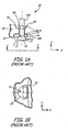
- FIG. 1A is a plan view of vertical assembly 10 of bolt 12, which is connecting first component 14 and second component 16.
- Bolt 12 is a conventional bolt that is known in the art.
- a longitudinal axis 13 of bolt 12 is oriented in a "vertical" direction, which is along the z-axis direction (see orthogonal x-z axes).
- First component 14 may be, for example, a rotor disk
- second component 16 may be, for example, a side plate.
- second component 16 includes groove 17, bolt 12 is not engaged with groove 17 in any way.
- Bolt 12 includes shank 18 with distal end 18A and a proximal end 18B, and head 20.
- bolt 12 is introduced into overlapping openings 22 in first and second components 14 and 16 in order to connect first and second components 14 and 16.
- Nut (or other fastening device) 24 which is attached to distal end 18A of shank 18, helps retain shank 18 within overlapping openings 22.
- bolt 12 Prior to attaching nut 24 or if nut 24 is detached from distal end 18A of bolt 12, bolt 12 is likely to move in the z-axis direction and "fall out" of openings 22.
- vertical assembly 10 is a part of a gas turbine engine because a loose bolt 12 in the gas turbine engine may adversely affect the engine operation, force disassembly of the gas turbine engine to remove bolt 12, or cause damage to other hardware within the gas turbine engine.
- FIG. 1B is a plan view of bolt 12 taken along line A-A in FIG. 1A.
- a part of head 20 of bolt 12 is engaged with retention device 26 (i.e., the part of head 20 that is shown in phantom in FIG. 1B), and retention device 26 holds head 20 in its original position (or close to its original position) prior to attaching nut 24 (shown in FIG. 1A) to shank 18.
- Retention device 26 limits movement of bolt 12 along its longitudinal axis 13 during assembly.
- Retention device 26 is any retention device known in the art, such as a lock tab, lock wire, or tab washer. As stated in the Background, the use of retention device 26 complicates an assembly process in some situations, such as small-scale assemblies and/or assemblies including a large quantity of bolts that need to be retained.
- a bolt in accordance with the present invention addresses the difficulties associated with retention devices because the inventive bolt is self-retained. More particularly, the bolt includes a retention flange that is configured to engage with a component. The mating of the flange and groove limits movement of the bolt along its longitudinal axis, even without the use of a nut (or other fastening device).
- the bolt configuration of the present invention may be used instead of, or in addition to, an external retention device (e.g., retention device 26). Because an external retention device is not necessary, a bolt in accordance with the present invention is better suited for small-scale assemblies than bolt 12 of FIGS. 1A and 1B, which requires external retention device 26 in order to limit movement in a direction along the longitudinal axis of the bolt. Furthermore, the elimination of an external retention device also helps to streamline an assembly process, reduces the number of parts required for assembly, and may reduce the cost and/or risk of improper installation.
- a bolt in accordance with the present invention is useful in gas turbine engines, where it is common for components to be assembled with bolts in a vertical orientation, because the retention flange of the bolt holds the bolt in position prior to securing the bolt in position with a nut.
- a bolt in accordance with the present invention is also useful in applications in which it is especially crucial that components remain connected and bolts do not loosen.
- the retention flange of the bolt helps to ensure that the bolt remains in place, even if a nut (or other fastening device) is detached from the bolt, such as when the components are being disassembled.
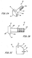
- FIG. 2A is a perspective view of bolt 30 in accordance with a first embodiment of the present invention.
- Bolt 30 includes shank 32, with distal end 32A and proximal end 32B, and head 34, which is adjacent to proximal end 32B of shank 32.
- head 34 is integral with shank 32 (i.e., shank 32 and head 34 are formed from a single piece of material), while in other embodiments, head 34 and shank 32 are separate pieces that are attached using any suitable attachment means known in the art, such as, but not limited to, mechanical attachment means (e.g., threads), welding, or adhesive.
- head 34 of bolt 30 is shaped to resist rotation when torque is applied. While head 34 of bolt 30 is shown to be a slab (or tee) head, head 34 may be any shape known in the art to resist rotation, such as, but not limited to, a D-shape.
- Head 34 includes first flange 36 and second flange 38, where first flange 36 and second flange 38 are generally perpendicular to each other. First and second flanges 36 and 38 are each configured to engage with a groove in a component after bolt 30 is assembled in an assembly. This is illustrated and further discussed in reference to FIG. 3.
- FIG. 2B is a plan view of bolt 30 of FIG. 2A, and illustrates flange 38 extending from head 34.
- Distal end 32A of shank 32 is tapered and threaded.
- the tapered end 32A of shank 32 is a design element that may be modified in alternate embodiments.
- proximal end 32B of shank 32 may also bc tapered (e.g., tapered proximal end 72B of shank 72 in the embodiment of bolt 70 shown in FIGS. 6A-6C).
- One skilled in the art may also modify the dimensions of shank 32, head 34, and flanges 36 and 38 in accordance with the particular application of bolt 30.
- flange 38 is shown to be adjacent to distal end 34A of head 34, in an alternate embodiment, flange 38 is adjacent to proximal end 34B of head 34. Similarly, flange 36 can be adjacent to proximal end 34A of head 34 in an alternate embodiment.
- FIG. 2C is a plan view of bolt 30 of FIG. 2A and illustrates flanges 36 and 38 extending from head 34.
- Depth D) of flange 36 and depth D 2 of flange 38 depend upon the size of the groove with which flange 36 and flange 38, respectively, are configured to engage.
- the grooves with which flanges 36 and 38 are configured to engage preexist in a component, in which case flanges 36 and 38 are shaped and sized to fit within the preexisting groove.
- the shape and size of flanges 36 and 38 are first determined, and then a corresponding groove is formed in a component.
- depth D) of flange 36 and depth D 2 of flange 38 are equal, while in other embodiments, depth D 1 of flange 36 and depth D 2 of flange 38 are different.
- FIG. 3 is a plan view of gas turbine engine vane assembly 40 that includes bolt 30 of FIGS. 2A-2C.
- Bolt 30 is vertically oriented in assembly 40, and connects vane assembly flange 42, seal 44, inner duct segment assembly 46, and spacer 48.
- shaft 32 of bolt 30 is introduced into openings 50 within vane assembly flange 42, seal 44, inner duct segment assembly 46, spacer 48, and head 34 of bolt 30 engages with vane assembly flange 42.
- Inner air seal 49 is positioned between seal 44 and inner duct assembly 46.
- head 34 of bolt 30 is preferably larger than the size of openings 50 so that head 34 of bolt 30 does not move through openings 50.
- a washer may be used in conjunction with bolt 30.
- Flange 38 of head 34 of bolt 30 is engaged with groove 52 in vane assembly flange 42, which helps limits movement of bolt 30 in a z-direction (i.e., in a direction along its the longitudinal axis 56 of bolt 30), where orthogonal x-z axes are shown in. FIG. 3.
- bolt 30 substantially retains its original position prior to the attachment of nut 54, and/or even if nut 54 is detached from distal end 32A.
- vane assembly flange 42 can be referred to as the "mating part" for bolt 30.
- flange 36 rather than flange 38, can engage with groove 52, in which case bolt 30 would be rotated about 90° because flange 36 and flange 38 are generally perpendicular to each other.
- Self-locking nut 54 is attached to distal end 32A of shank 32 and also helps secure bolt 30 in place with respect to vane assembly flange 42, seal 44, inner duct segment assembly 46, and spacer 48.
- self-locking nut 54 helps limit movement of bolt 30 along the z-axis direction.
- the mating of flange 38 with groove 52 helps to ensure that bolt 30 will retain its position and vane assembly flange 42, seal 44, inner duct segment assembly 46, and spacer 48 will remain connected, even before self-locking nut 54 is attached from distal end 32A of shank or if self-locking nut 54 is detached from distal end 32A of shank 32.
- Assembly 40 is shown as an example of an assembly in which bolt 30 in accordance with the present invention may be incorporated into.
- Bolt 30 is suitable for use in any other assembly where a bolt connects components together. If a component does not include a groove for flange 36 and/or 38 to mate with, a corresponding groove can be formed in the component.
- FIGS. 4A-4C illustrate three different orientations of bolt 30 as bolt 30 is installed in assembly 60 (which may be, for example, gas turbine vane assembly 40 of FIG. 3).
- assembly 60 which may be, for example, gas turbine vane assembly 40 of FIG. 3.
- bolt 30 is first introduced into opening 62 (shown in phantom) in one or more components of assembly 60, bolt 30 is in a first orientation, as shown in FIG. 4A.
- Bolt 30 only includes one orientation that allows it to be introduced into opening 62 (shown in FIG. 4A) due to the configuration (or shape) of head 34 of bolt 30, which is configured (or shaped) to resist rotation when torque is applied.
- head 34 of bolt interferes with mating part 64, and bolt 30 resists introduction into opening 62.
- Opening 62 may be in mating part 64 or in another part.
- Mating part 64 includes groove 66 (shown in phantom), which is configured to mate with flanges 36 and 38.
- FIG. 4B shows an installation step following the step shown in FIG. 4A, where bolt 30 is rotated in a counterclockwise direction (shown by arrow 68) in order to engage flange 38 with groove 66 in mating part 64, and thus secure bolt 30 in position.
- an "assembly" torque is applied to rotate slab head 34 bolt 30 in direction 68.
- FIG. 4C shows a final orientation of bolt 30 after flange 38 is mated with groove 66. In this orientation, flange 38 fully engages groove 66, thus retaining bolt 30 in position, and allowing bolt 30 to resist movement in a direction along longitudinal axis 56 (shown in FIG. 3) of bolt 30.
- Bolt 30 can be released from opening 62 by rotating bolt 30 to the orientation shown in FIG. 4A, which releases flange 38 from groove 66.
- bolt 30 is rotated about 90° in a clockwise direction, which may occur, for example, if a disassembly torque is applied to bolt 30.
- the two generally perpendicular flanges 36 and 38 of bolt 30 enable bolt 30 to remain engaged with groove 66 at disassembly.
- flange 36 engages with groove 66 in mating part 64. Without flange 36, bolt 30 would no longer remain engaged with groove 66 and bolt 30 could potentially move in a direction along its longitudinal axis.
- bolt 30 may be desirable for bolt 30 to retain its position at disassembly if assembly 60 is a part of an apparatus that is sensitive to loose parts (e.g., a loose bolt may interfere with the operation of a gas turbine engine). Furthermore, if only one component is being disconnected from assembly 60, bolt 30 should remain in place in order to connect the remaining components of assembly 60.
- these rotation angles are provided as examples, and one skilled in the art can modify the position of flanges 36 and 38 with respect to head 34 in order to accommodate other rotation angles.
- the present invention also includes bolts with flanges in different configurations than that of bolt 30.
- a second embodiment of a bolt is illustrated in FIGS. 6A-6C, and a third embodiment of a bolt is illustrated in FIGS. 7A-7C.
- FIG. 6A is a perspective view of bolt 70 in accordance with a second embodiment of the present invention.
- Bolt 70 includes shank 72, with distal end 72A and proximal end 72B, and head 74, which is adjacent to proximal end 72B of shank 72.
- head 74 and shank 72 can be an integral unit or separate pieces that are attached to each other.
- Bolt 70 is similar to bolt 30 of FIGS. 2A-2C, except that flanges 76 and 78 on head 74 of bolt 70 are generally parallel to each other, rather than generally perpendicular, as with flanges 36 and 38 of bolt 30.
- FIG. 6B is a plan view of bolt 70 of FIG. 6A; and illustrates flanges 76 and 78 extending from head 74. Both distal end 72A and proximal end 72B of shank 72 are tapered. One skilled in the art may modify the dimensions of shank 72, head 74, and flanges 76 and 78 in accordance with the particular application of bolt 70. Just as with head 34 of bolt 12 of FIGS. 2A-2C, in an alternate embodiment, flanges 76 and 78 are adjacent to proximal end 74B of head 74, rather than adjacent to distal end 74A, as shown in the embodiment shown in FIG. 6B.
- FIG. 6C is a plan view of bolt 70 of FIG. 6A and illustrates flanges 76 and 78 extending from head 74. Because of the shape of flanges 76 and 78, head 74 includes a U-shaped protrusion.
- FIG. 7A is a perspective view of bolt 80 in accordance with a third embodiment of the present invention.
- Bolt 80 includes shank 82, with distal end 82A and proximal end 82B, and head 84, which is adjacent to proximal end 82B of shank 82.
- head 84 and shank 82 can be an integral unit or separate pieces that are attached to each other.
- Bolt 80 is similar to bolt 30 of FIGS. 2A-2C and bolt 70 of FIGS.
- head 84 includes flange 86, which extends around a full circumference of head 84, rather than including two separate flanges on two sides of head 84, as with flanges 36 and 38 of bolt 30 and flanges 76 and 78 of bolt 70.
- FIG. 7B is a plan view of bolt 80 of FIG. 7A, and illustrates flange 86 extending from head 84.
- both distal end 82A and proximal end 82B of shank 82 are tapered.
- One skilled in the art may modify the dimensions of shank 82, head 84, and flange 86 in accordance with the particular application of bolt 80.
- flange 86 is adjacent to proximal end 84B of head 84 in an alternate embodiment, rather than adjacent to distal end 84A of head 84, as shown in the embodiment of FIG. 7B.
- FIG. 7C is a plan view of bolt 80 of FIG. 6A and illustrates flange 86 extending around a full circumference of head 84.
- a groove in a mating part must be interrupted in order to introduce flange 86 into the groove.
- FIG. 8 illustrates one embodiment of groove 88 (shown in phantom) in mating part 89, where the groove 88 includes gap 90. Because flange 86 of bolt 80 extends around the full circumference of head 84 of bolt 80, it is difficult for flange 86 to access groove 88. Gap 90 provides an access opening to groove 88. As FIG. 8 illustrates, with the particular size and configuration of gap 90, head 84 of bolt 80 must be in a specific orientation in order for head 84 to fit within gap 90. Bolt 80 may subsequently be rotated in a counterclockwise (or clockwise) direction in order to engage flange 86 with groove 80.
- the present invention is a bolt that includes a flange configured to engage with a groove in a component in order to limit movement of the bolt in a direction along its longitudinal axis. While three embodiments of bolts in accordance with the present invention are described above, other bolt designs are also contemplated. For example, the shape of the bolt head and/or the exact location of the flanges may be modified in alternate embodiments without departing from the scope of the invention.
Landscapes
- Engineering & Computer Science (AREA)
- General Engineering & Computer Science (AREA)
- Mechanical Engineering (AREA)
- Connection Of Plates (AREA)
Abstract
Description
- The present invention relates to a bolt and a bolt assembly. More particularly, the present invention relates to a self-retaining bolt with a retention flange, and a bolt assembly including a component with a groove and a self-retaining bolt with a retention flange that is configured to mate with the groove.
- A bolt having a shank and a head is often used to connect two or more components together. After the bolt is assembled with the components, it is typically desirable for the bolt to remain in place in order to keep the components connected, and in the case of a bolt being used in a moving machine, engine, or otherwise, in order to prevent the bolt from interfering with other parts of the machine or engine.
- Slab (or tee) head and D-head bolts are configured to resist rotation about their respective longitudinal axes (which is typically represented by an imaginary line running through the shank of the bolt) when torque is applied, and thus, help prevent the bolt from unfastening. In some applications, it is also desirable for slab and D-head bolts (as well as other types of bolts) to resist movement in a direction along the longitudinal axis of the bolt. When a bolt is "vertically assembled," a longitudinal axis of the bolt is oriented vertically (i.e., along a z-axis direction, where orthogonal x-z axes are shown in FIG. 1A) during installation or after the bolt is installed. This configuration may be found in many different types of assemblies, including, for example, a gas turbine engine application, where vertically oriented bolts are common during the assembly process. Due to gravity and other forces, such as forces generated by vibrational movement of the assembly, the vertical orientation encourages the bolt to move vertically and out of the socket (or opening) in which the bolt is positioned. In the case of a gas turbine engine, or another assembly with moving components, a retention device, such as a lock tab, a lock wire, or a tab washer, may be used to hold the bolt in place during assembly, prior to attaching a nut to the bolt. A nut threaded onto the bolt shank (opposite the head of the bolt) typically secures the bolt during engine operation.
- In some applications, the use of a retention device complicates the assembly process and may cause ergonomic concerns. For example, in small-scale assemblies, it may be difficult to apply the retention device and/or the retention device may not fit within the available space. Furthermore, in assemblies including a large quantity of bolts that need to be retained, the addition of multiple retention devices may increase assembly time and cost, as well as increase the risk of an improper installation.
- The present invention is a bolt that comprises a shank with a distal end and a proximal end, and a head adjacent to the proximal end of the shank. The head includes a retention flange configured to engage with a groove in a component.
-
- FIG. 1A is a plan view of a vertical assembly of a prior art bolt, which is connecting a first component and a second component.
- FIG. 1B is a plan view of the bolt of FIG. 1A taken along line A-A in FIG. 1A and shows a prior art retention device.
- FIGS. 2A - 2C are perspective and plan views of a first embodiment of a bolt in accordance with the present invention.
- FIG. 3 is a plan view of a gas turbine engine vane assembly that includes the bolt shown in FIGS. 2A-2C.
- FIGS. 4A - 4C illustrate an installation of a bolt in accordance with the first embodiment of the present invention.
- FIG. 5 is a plan view of the installed bolt of FIG. 4C, after the bolt is rotated in an opposite direction.
- FIGS. 6A - 6C are perspective and plan views of a second embodiment of a bolt in accordance with the present invention.
- FIGS. 7A - 7C are perspective and plan views of a third embodiment of a bolt in accordance with the present invention.
- FIG. 8 illustrates an installation of the bolt of FIGS. 7A-7C, where the bolt is ' introduced into a gap in a groove in a mating part.
- The present invention is a self-retaining bolt that is configured to resist movement in a direction along its longitudinal axis (which is represented by an imaginary line running through the shank of the bolt) after the bolt is engaged with a groove in a component. Hereinafter, a "groove in a component" encompasses any type of groove, whether the groove is defined in a single component, or whether a groove is defined by a space between two or more components.
- A bolt in accordance with the present invention includes a shank, which has a distal end and a proximal end, and a head adjacent to the proximal end of the shank and including a flange that is configured to engage with a groove in a component. In some embodiments, the shank is at least partially threaded. A bolt in accordance with the present invention is "self-retaining" because when the flange of the bolt head is engaged with a groove in a component, the bolt is inclined to resist movement in a direction along its longitudinal axis and retain its position. Such a bolt is "self-retaining" because it does not require a tool or a separate retention device to hold the bolt in position, as discussed in the Background section. In this way, the flange on the head of the bolt can also be referred to as a "retention flange." In one embodiment, the bolt head is also shaped to resist rotation when torque is applied, and thus retain its orientation. Examples of suitable bolt head shapes include, but are not limited to, a slab (or tee) or D-shaped head, which are known in the art. In the embodiments discussed below, the flange of the bolt head extends in a generally lateral direction (i.e., generally perpendicular to the longitudinal axis of the bolt) and mates with a groove in the component, where the groove also extends in a generally lateral direction.
- As stated in the Background section, a retention device (e.g., a lock tab, a lock wire, or a tab washer) is conventionally used to limit movement of a bolt along its longitudinal axis during an assembly process in which the bolt is vertically assembled and before a nut is attached to the bolt. It is especially desirable to limit movement of the bolt along its longitudinal axis in a vertical assembly, where the longitudinal axis of the bolt is oriented in a vertical direction (i.e., z-axis direction). FIG. 1A is a plan view of
vertical assembly 10 ofbolt 12, which is connectingfirst component 14 andsecond component 16.Bolt 12 is a conventional bolt that is known in the art. Alongitudinal axis 13 ofbolt 12 is oriented in a "vertical" direction, which is along the z-axis direction (see orthogonal x-z axes).First component 14 may be, for example, a rotor disk, andsecond component 16 may be, for example, a side plate. Althoughsecond component 16 includes groove 17,bolt 12 is not engaged with groove 17 in any way. -
Bolt 12 includesshank 18 withdistal end 18A and aproximal end 18B, andhead 20. Invertical assembly 10,bolt 12 is introduced into overlappingopenings 22 in first andsecond components second components distal end 18A ofshank 18, helps retainshank 18 within overlappingopenings 22. Prior to attachingnut 24 or ifnut 24 is detached fromdistal end 18A ofbolt 12,bolt 12 is likely to move in the z-axis direction and "fall out" ofopenings 22. This is especially undesirable ifvertical assembly 10 is a part of a gas turbine engine because aloose bolt 12 in the gas turbine engine may adversely affect the engine operation, force disassembly of the gas turbine engine to removebolt 12, or cause damage to other hardware within the gas turbine engine. - As shown in FIG. 1 B, a prior
art retention device 26 is attached tobolt 12head 20 in order to limit movement ofbolt 12 along its longitudinal axis 13 (which is perpendicular to the plane of the image of FIG. 1B) beforenut 24 is attached. FIG. 1B is a plan view ofbolt 12 taken along line A-A in FIG. 1A. A part ofhead 20 ofbolt 12 is engaged with retention device 26 (i.e., the part ofhead 20 that is shown in phantom in FIG. 1B), andretention device 26 holdshead 20 in its original position (or close to its original position) prior to attaching nut 24 (shown in FIG. 1A) toshank 18.Retention device 26 limits movement ofbolt 12 along itslongitudinal axis 13 during assembly.Retention device 26 is any retention device known in the art, such as a lock tab, lock wire, or tab washer. As stated in the Background, the use ofretention device 26 complicates an assembly process in some situations, such as small-scale assemblies and/or assemblies including a large quantity of bolts that need to be retained. - A bolt in accordance with the present invention addresses the difficulties associated with retention devices because the inventive bolt is self-retained. More particularly, the bolt includes a retention flange that is configured to engage with a component. The mating of the flange and groove limits movement of the bolt along its longitudinal axis, even without the use of a nut (or other fastening device). The bolt configuration of the present invention may be used instead of, or in addition to, an external retention device (e.g., retention device 26). Because an external retention device is not necessary, a bolt in accordance with the present invention is better suited for small-scale assemblies than
bolt 12 of FIGS. 1A and 1B, which requiresexternal retention device 26 in order to limit movement in a direction along the longitudinal axis of the bolt. Furthermore, the elimination of an external retention device also helps to streamline an assembly process, reduces the number of parts required for assembly, and may reduce the cost and/or risk of improper installation. - A bolt in accordance with the present invention is useful in gas turbine engines, where it is common for components to be assembled with bolts in a vertical orientation, because the retention flange of the bolt holds the bolt in position prior to securing the bolt in position with a nut. A bolt in accordance with the present invention is also useful in applications in which it is especially crucial that components remain connected and bolts do not loosen. In particular, the retention flange of the bolt helps to ensure that the bolt remains in place, even if a nut (or other fastening device) is detached from the bolt, such as when the components are being disassembled.
- FIG. 2A is a perspective view of
bolt 30 in accordance with a first embodiment of the present invention.Bolt 30 includesshank 32, withdistal end 32A andproximal end 32B, andhead 34, which is adjacent toproximal end 32B ofshank 32. In some embodiments,head 34 is integral with shank 32 (i.e.,shank 32 andhead 34 are formed from a single piece of material), while in other embodiments,head 34 andshank 32 are separate pieces that are attached using any suitable attachment means known in the art, such as, but not limited to, mechanical attachment means (e.g., threads), welding, or adhesive. In the first embodiment of the present invention,head 34 ofbolt 30 is shaped to resist rotation when torque is applied. Whilehead 34 ofbolt 30 is shown to be a slab (or tee) head,head 34 may be any shape known in the art to resist rotation, such as, but not limited to, a D-shape. -
Head 34 includesfirst flange 36 andsecond flange 38, wherefirst flange 36 andsecond flange 38 are generally perpendicular to each other. First andsecond flanges bolt 30 is assembled in an assembly. This is illustrated and further discussed in reference to FIG. 3. - FIG. 2B is a plan view of
bolt 30 of FIG. 2A, and illustratesflange 38 extending fromhead 34.Distal end 32A ofshank 32 is tapered and threaded. Thetapered end 32A ofshank 32 is a design element that may be modified in alternate embodiments. For example,proximal end 32B ofshank 32 may also bc tapered (e.g., taperedproximal end 72B ofshank 72 in the embodiment ofbolt 70 shown in FIGS. 6A-6C). One skilled in the art may also modify the dimensions ofshank 32,head 34, andflanges bolt 30. Althoughflange 38 is shown to be adjacent todistal end 34A ofhead 34, in an alternate embodiment,flange 38 is adjacent toproximal end 34B ofhead 34. Similarly,flange 36 can be adjacent toproximal end 34A ofhead 34 in an alternate embodiment. - FIG. 2C is a plan view of
bolt 30 of FIG. 2A and illustratesflanges head 34. Depth D) offlange 36 and depth D2 offlange 38 depend upon the size of the groove with whichflange 36 andflange 38, respectively, are configured to engage. In some applications, the grooves with whichflanges flanges flange 36 and depth D2 offlange 38 are equal, while in other embodiments, depth D1 offlange 36 and depth D2 offlange 38 are different. - FIG. 3 is a plan view of gas turbine
engine vane assembly 40 that includesbolt 30 of FIGS. 2A-2C.Bolt 30 is vertically oriented inassembly 40, and connectsvane assembly flange 42,seal 44, innerduct segment assembly 46, andspacer 48. Specifically,shaft 32 ofbolt 30 is introduced intoopenings 50 withinvane assembly flange 42,seal 44, innerduct segment assembly 46,spacer 48, andhead 34 ofbolt 30 engages withvane assembly flange 42.Inner air seal 49 is positioned betweenseal 44 andinner duct assembly 46. As known in the art,head 34 ofbolt 30 is preferably larger than the size ofopenings 50 so thathead 34 ofbolt 30 does not move throughopenings 50. Of course, ifhead 34 of bold 30 is the same size as or smaller thanopenings 50, a washer may be used in conjunction withbolt 30. -
Flange 38 ofhead 34 ofbolt 30 is engaged withgroove 52 invane assembly flange 42, which helps limits movement ofbolt 30 in a z-direction (i.e., in a direction along its thelongitudinal axis 56 of bolt 30), where orthogonal x-z axes are shown in. FIG. 3. As a result of the mating offlange 38 andgroove 52,bolt 30 substantially retains its original position prior to the attachment ofnut 54, and/or even ifnut 54 is detached fromdistal end 32A. Becauseflange 38 mates withgroove 52,vane assembly flange 42 can be referred to as the "mating part" forbolt 30. Alternatively,flange 36, rather than flange 38, can engage withgroove 52, in whichcase bolt 30 would be rotated about 90° becauseflange 36 andflange 38 are generally perpendicular to each other. - Self-locking
nut 54 is attached todistal end 32A ofshank 32 and also helpssecure bolt 30 in place with respect tovane assembly flange 42,seal 44, innerduct segment assembly 46, andspacer 48. In addition tomating flange 38 andgroove 52, self-lockingnut 54 helps limit movement ofbolt 30 along the z-axis direction. The mating offlange 38 withgroove 52 helps to ensure thatbolt 30 will retain its position andvane assembly flange 42,seal 44, innerduct segment assembly 46, andspacer 48 will remain connected, even before self-lockingnut 54 is attached fromdistal end 32A of shank or if self-lockingnut 54 is detached fromdistal end 32A ofshank 32. -
Assembly 40 is shown as an example of an assembly in whichbolt 30 in accordance with the present invention may be incorporated into.Bolt 30 is suitable for use in any other assembly where a bolt connects components together. If a component does not include a groove forflange 36 and/or 38 to mate with, a corresponding groove can be formed in the component. - FIGS. 4A-4C illustrate three different orientations of
bolt 30 asbolt 30 is installed in assembly 60 (which may be, for example, gasturbine vane assembly 40 of FIG. 3). Whenbolt 30 is first introduced into opening 62 (shown in phantom) in one or more components ofassembly 60,bolt 30 is in a first orientation, as shown in FIG. 4A.Bolt 30 only includes one orientation that allows it to be introduced into opening 62 (shown in FIG. 4A) due to the configuration (or shape) ofhead 34 ofbolt 30, which is configured (or shaped) to resist rotation when torque is applied. Ifbolt 30 is rotated to either of the orientations shown in FIGS. 4B or 4C,head 34 of bolt interferes withmating part 64, andbolt 30 resists introduction into opening 62. Opening 62 may be inmating part 64 or in another part.Mating part 64 includes groove 66 (shown in phantom), which is configured to mate withflanges - FIG. 4B shows an installation step following the step shown in FIG. 4A, where
bolt 30 is rotated in a counterclockwise direction (shown by arrow 68) in order to engageflange 38 withgroove 66 inmating part 64, and thussecure bolt 30 in position. As known in the art, an "assembly" torque is applied to rotateslab head 34bolt 30 indirection 68. FIG. 4C shows a final orientation ofbolt 30 afterflange 38 is mated withgroove 66. In this orientation,flange 38 fully engagesgroove 66, thus retainingbolt 30 in position, and allowingbolt 30 to resist movement in a direction along longitudinal axis 56 (shown in FIG. 3) ofbolt 30.Bolt 30 can be released from opening 62 by rotatingbolt 30 to the orientation shown in FIG. 4A, which releasesflange 38 fromgroove 66. - In FIG. 5,
bolt 30 is rotated about 90° in a clockwise direction, which may occur, for example, if a disassembly torque is applied to bolt 30. As shown in FIG. 5, the two generallyperpendicular flanges bolt 30 enablebolt 30 to remain engaged withgroove 66 at disassembly. After a disassembly torque is applied to bolt 30,flange 36 engages withgroove 66 inmating part 64. Withoutflange 36,bolt 30 would no longer remain engaged withgroove 66 andbolt 30 could potentially move in a direction along its longitudinal axis. It may be desirable forbolt 30 to retain its position at disassembly ifassembly 60 is a part of an apparatus that is sensitive to loose parts (e.g., a loose bolt may interfere with the operation of a gas turbine engine). Furthermore, if only one component is being disconnected fromassembly 60,bolt 30 should remain in place in order to connect the remaining components ofassembly 60. Of course, these rotation angles are provided as examples, and one skilled in the art can modify the position offlanges head 34 in order to accommodate other rotation angles. - The present invention also includes bolts with flanges in different configurations than that of
bolt 30. A second embodiment of a bolt is illustrated in FIGS. 6A-6C, and a third embodiment of a bolt is illustrated in FIGS. 7A-7C. - FIG. 6A is a perspective view of
bolt 70 in accordance with a second embodiment of the present invention.Bolt 70 includesshank 72, withdistal end 72A andproximal end 72B, andhead 74, which is adjacent toproximal end 72B ofshank 72. As withbolt 30 of FIGS. 2A-2C,head 74 andshank 72 can be an integral unit or separate pieces that are attached to each other.Bolt 70 is similar to bolt 30 of FIGS. 2A-2C, except that flanges 76 and 78 onhead 74 ofbolt 70 are generally parallel to each other, rather than generally perpendicular, as withflanges bolt 30. - FIG. 6B is a plan view of
bolt 70 of FIG. 6A; and illustratesflanges head 74. Bothdistal end 72A andproximal end 72B ofshank 72 are tapered. One skilled in the art may modify the dimensions ofshank 72,head 74, andflanges bolt 70. Just as withhead 34 ofbolt 12 of FIGS. 2A-2C, in an alternate embodiment,flanges proximal end 74B ofhead 74, rather than adjacent todistal end 74A, as shown in the embodiment shown in FIG. 6B. - FIG. 6C is a plan view of
bolt 70 of FIG. 6A and illustratesflanges head 74. Because of the shape offlanges head 74 includes a U-shaped protrusion. - FIG. 7A is a perspective view of
bolt 80 in accordance with a third embodiment of the present invention.Bolt 80 includesshank 82, withdistal end 82A andproximal end 82B, andhead 84, which is adjacent toproximal end 82B ofshank 82. As withbolt 30 of FIGS. 2A-2C,head 84 andshank 82 can be an integral unit or separate pieces that are attached to each other.Bolt 80 is similar to bolt 30 of FIGS. 2A-2C and bolt 70 of FIGS. 6A-6C, excepthead 84 includesflange 86, which extends around a full circumference ofhead 84, rather than including two separate flanges on two sides ofhead 84, as withflanges bolt 30 andflanges bolt 70. - FIG. 7B is a plan view of
bolt 80 of FIG. 7A, and illustratesflange 86 extending fromhead 84. As withbolt 70 of FIGS. 6A - 6C, bothdistal end 82A andproximal end 82B ofshank 82 are tapered. One skilled in the art may modify the dimensions ofshank 82,head 84, andflange 86 in accordance with the particular application ofbolt 80. Just as with the first and second embodiments ofbolt 12 andbolt 70, respectively,flange 86 is adjacent toproximal end 84B ofhead 84 in an alternate embodiment, rather than adjacent todistal end 84A ofhead 84, as shown in the embodiment of FIG. 7B. - FIG. 7C is a plan view of
bolt 80 of FIG. 6A and illustratesflange 86 extending around a full circumference ofhead 84. - In some embodiments, a groove in a mating part must be interrupted in order to introduce
flange 86 into the groove. FIG. 8 illustrates one embodiment of groove 88 (shown in phantom) inmating part 89, where thegroove 88 includesgap 90. Becauseflange 86 ofbolt 80 extends around the full circumference ofhead 84 ofbolt 80, it is difficult forflange 86 to accessgroove 88.Gap 90 provides an access opening to groove 88. As FIG. 8 illustrates, with the particular size and configuration ofgap 90,head 84 ofbolt 80 must be in a specific orientation in order forhead 84 to fit withingap 90.Bolt 80 may subsequently be rotated in a counterclockwise (or clockwise) direction in order to engageflange 86 withgroove 80. - The present invention is a bolt that includes a flange configured to engage with a groove in a component in order to limit movement of the bolt in a direction along its longitudinal axis. While three embodiments of bolts in accordance with the present invention are described above, other bolt designs are also contemplated. For example, the shape of the bolt head and/or the exact location of the flanges may be modified in alternate embodiments without departing from the scope of the invention.
- The terminology used herein is for the purpose of description, not limitation. Specific structural and functional details disclosed herein are not to be interpreted as limiting, but merely as bases for teaching one skilled in the art to variously employ the present invention. Although the present invention has been described with reference to preferred embodiments, workers skilled in the art will recognize that changes may be made in form and detail without departing from the scope of the invention.
Claims (16)
- A bolt (30;70;80) comprising:a shank (32;72;82) including a distal end (32A;72A;82A) and a proximal end (32B;72B;82B); anda head (34;74;84) adjacent to the proximal end (32B;72B;82B) of the shank (32;72;82) and including a retention flange (36,38;76,78;86) configured to engage with a groove (52;88) in a component.
- The bolt of claim 1, wherein the shank (32;72;82) is threaded along the distal end (32A;72A;82A).
- The bolt of claim 1 or 2, wherein the head (34;74;84) is a shape selected from a group consisting of: a slab head and a D-head.
- The bolt of any preceding claim, wherein the retention flange (86) extends around a full circumference of the head (84).
- The bolt of claim 1, 2 or 3, wherein the head (34) comprises:a first side;a second side generally perpendicular to the first side;a third side generally perpendicular to the second side;a fourth side generally perpendicular the third side; anda fifth side extending between the first side and the fourth side.
- The bolt of claim 5, wherein the retention flange includes:a first retention flange (36) positioned along the first side of the head; anda second retention flange (38) positioned along the fourth side of the head.
- The bolt of claim 1, 2 or 3, wherein the retention flange comprises:a first flange (76); anda second flange (78) generally parallel to the first flange.
- The bolt of claim 1, 2 or 3, wherein the retention flange comprises:a first flange (36); anda second flange (38) generally perpendicular to the first flange (36).
- A bolt assembly comprising:a component comprising a groove (52;88); anda bolt (30;70;80) as claimed in any preceding claim.
- The bolt assembly of claim 9, wherein the head (34;74;84) of the bolt (30;70;80) is shaped to resist rotation with respect to the component.
- The bolt assembly of claim 10, wherein the head (34;74;84) of the bolt (30;70;80) is a shape selected from a group consisting of: a slab head and D-head.
- The bolt assembly of claim 9, 10 or 11, wherein the retention flange of the head of the bolt extends around a full circumference of the head and the groove (88) in the component includes a gap (90).
- The bolt assembly of any of claims 9 to 12, wherein the component is a gas turbine engine component.
- The bolt assembly of any of claims 9 to 13, wherein the component comprises:a first component; anda second component adjacent to the first component, wherein the groove is defined by a space between the first and second components.
- A method of attaching a first component (42) comprising a first opening (50) and a groove (52) and a second component (49) comprising a second opening (50), the method comprising:aligning a bolt (30;70;80) as claimed in any of claims 1 to 8 with the first and second openings (50);introducing the bolt (30;70;80) into the first and second openings (50); androtating the bolt in order to engage the retention flange (36;38;76;78;86) with the groove in the first component (42).
- The method of claim 15, and further comprising:attaching a fastening apparatus (54) onto the shank (32;72;82) of the bolt (30;70;80), wherein the head (34;74;84) of the bolt (30;70;80) and the fastening apparatus (54) are on opposite sides of the first and second components.
Applications Claiming Priority (1)
| Application Number | Priority Date | Filing Date | Title |
|---|---|---|---|
| US11/372,780 US20070212192A1 (en) | 2006-03-10 | 2006-03-10 | Self-retaining bolt |
Publications (1)
| Publication Number | Publication Date |
|---|---|
| EP1832761A1 true EP1832761A1 (en) | 2007-09-12 |
Family
ID=38134155
Family Applications (1)
| Application Number | Title | Priority Date | Filing Date |
|---|---|---|---|
| EP07250901A Withdrawn EP1832761A1 (en) | 2006-03-10 | 2007-03-05 | Self-retaining bolt |
Country Status (3)
| Country | Link |
|---|---|
| US (1) | US20070212192A1 (en) |
| EP (1) | EP1832761A1 (en) |
| JP (1) | JP2007240001A (en) |
Families Citing this family (6)
| Publication number | Priority date | Publication date | Assignee | Title |
|---|---|---|---|---|
| US8043062B2 (en) * | 2008-09-04 | 2011-10-25 | Mitsubishi Heavy Industries, Ltd. | Turbine rotor and turbine having the same |
| US8496692B2 (en) * | 2009-09-21 | 2013-07-30 | Jmea Corporation | Locking securing member |
| US8967978B2 (en) * | 2012-07-26 | 2015-03-03 | Pratt & Whitney Canada Corp. | Axial retention for fasteners in fan joint |
| JP2014137111A (en) * | 2013-01-17 | 2014-07-28 | Daiwa Kasei Kogyo Kk | Insert structure of clip |
| US10563542B2 (en) | 2016-05-23 | 2020-02-18 | United Technologies Corporation | Retention hardware |
| CN110966249B (en) * | 2019-12-18 | 2025-03-14 | 珠海格力电器股份有限公司 | Impeller assembly and compressor with streamlined locking member |
Citations (4)
| Publication number | Priority date | Publication date | Assignee | Title |
|---|---|---|---|---|
| DE29515492U1 (en) * | 1994-11-18 | 1995-11-30 | Geberit Technik AG, Jona, St.Gallen | Connection arrangement |
| US5603594A (en) * | 1995-03-31 | 1997-02-18 | Uni Star Industries, Inc. | Fastener retention system |
| DE19737159A1 (en) * | 1997-08-26 | 1999-03-04 | Ejot Kunststofftech Gmbh | Plastics holder for mounting pipes on objects |
| US20040175252A1 (en) * | 2003-03-03 | 2004-09-09 | Kurczynski Richard J. | Fastener and washer assembly and method of forming same |
Family Cites Families (4)
| Publication number | Priority date | Publication date | Assignee | Title |
|---|---|---|---|---|
| US3812756A (en) * | 1970-02-11 | 1974-05-28 | M Wenger | Positive lock self-retained fastener |
| US4734001A (en) * | 1985-07-17 | 1988-03-29 | Bennett Bruce A | Locking fastener |
| US4887949A (en) * | 1988-03-30 | 1989-12-19 | United Technologies Corporation | Bolt retention apparatus |
| US6619915B1 (en) * | 2002-08-06 | 2003-09-16 | Power Systems Mfg, Llc | Thermally free aft frame for a transition duct |
-
2006
- 2006-03-10 US US11/372,780 patent/US20070212192A1/en not_active Abandoned
-
2007
- 2007-03-05 EP EP07250901A patent/EP1832761A1/en not_active Withdrawn
- 2007-03-09 JP JP2007059515A patent/JP2007240001A/en active Pending
Patent Citations (4)
| Publication number | Priority date | Publication date | Assignee | Title |
|---|---|---|---|---|
| DE29515492U1 (en) * | 1994-11-18 | 1995-11-30 | Geberit Technik AG, Jona, St.Gallen | Connection arrangement |
| US5603594A (en) * | 1995-03-31 | 1997-02-18 | Uni Star Industries, Inc. | Fastener retention system |
| DE19737159A1 (en) * | 1997-08-26 | 1999-03-04 | Ejot Kunststofftech Gmbh | Plastics holder for mounting pipes on objects |
| US20040175252A1 (en) * | 2003-03-03 | 2004-09-09 | Kurczynski Richard J. | Fastener and washer assembly and method of forming same |
Also Published As
| Publication number | Publication date |
|---|---|
| US20070212192A1 (en) | 2007-09-13 |
| JP2007240001A (en) | 2007-09-20 |
Similar Documents
| Publication | Publication Date | Title |
|---|---|---|
| JPH01176809A (en) | Fastener holder aggregate | |
| US6322306B1 (en) | Anti-rotation clips | |
| US11396901B2 (en) | Fastener locking | |
| US20090226318A1 (en) | Annulus filler | |
| CN101400902A (en) | Connecting element and connecting arrangement | |
| CN110945255B (en) | An active locking fastener | |
| US10975904B2 (en) | Clearance floating anchor nut | |
| US7435050B2 (en) | Split flange V-groove and anti-rotation mating system | |
| AU2019271947B2 (en) | Connecting Apparatus and Bolt Assembly | |
| US11905985B2 (en) | Systems and methods for misalignment adjustment utilizing double eccentric bushings | |
| US20180085871A1 (en) | Temporary fastening tool | |
| JP2007240001A (en) | Bolt, bolt assembly, and method for attaching component | |
| EP2837835A1 (en) | Attachment device for non-permanently attaching a child component to a parent component | |
| US7367766B2 (en) | Screw and nut fastening device | |
| CN111316006B (en) | An active locking fastener | |
| EP3693623B1 (en) | Fastener system | |
| EP4613639A1 (en) | A wing for an aircraft and method of connection of a connection assembly | |
| DE202019105173U1 (en) | Connection of at least two components of a fan | |
| EP2677186B1 (en) | Angular positioning arrangement | |
| US20220364585A1 (en) | Eccentric Bushing for Redundant Pinning of Removable Panels | |
| CN205480002U (en) | A subassembly for keeping fastening member | |
| GB2588018A (en) | Fastener locking | |
| US5445470A (en) | Tab locked pin attachment mechanism | |
| JP2681876B2 (en) | Manufacturing method of universal joint | |
| JP2002055312A (en) | Structure of lens mount and lens mount |
Legal Events
| Date | Code | Title | Description |
|---|---|---|---|
| PUAI | Public reference made under article 153(3) epc to a published international application that has entered the european phase |
Free format text: ORIGINAL CODE: 0009012 |
|
| AK | Designated contracting states |
Kind code of ref document: A1 Designated state(s): AT BE BG CH CY CZ DE DK EE ES FI FR GB GR HU IE IS IT LI LT LU LV MC MT NL PL PT RO SE SI SK TR |
|
| AX | Request for extension of the european patent |
Extension state: AL BA HR MK YU |
|
| 17P | Request for examination filed |
Effective date: 20070927 |
|
| 17Q | First examination report despatched |
Effective date: 20071031 |
|
| AKX | Designation fees paid |
Designated state(s): DE FR GB |
|
| STAA | Information on the status of an ep patent application or granted ep patent |
Free format text: STATUS: THE APPLICATION IS DEEMED TO BE WITHDRAWN |
|
| 18D | Application deemed to be withdrawn |
Effective date: 20081219 |