EP1832716A2 - Segmented component seal - Google Patents
Segmented component seal Download PDFInfo
- Publication number
- EP1832716A2 EP1832716A2 EP07250995A EP07250995A EP1832716A2 EP 1832716 A2 EP1832716 A2 EP 1832716A2 EP 07250995 A EP07250995 A EP 07250995A EP 07250995 A EP07250995 A EP 07250995A EP 1832716 A2 EP1832716 A2 EP 1832716A2
- Authority
- EP
- European Patent Office
- Prior art keywords
- bridging
- seal
- gap
- elements
- portions
- Prior art date
- Legal status (The legal status is an assumption and is not a legal conclusion. Google has not performed a legal analysis and makes no representation as to the accuracy of the status listed.)
- Granted
Links
- 238000011144 upstream manufacturing Methods 0.000 claims abstract description 9
- 239000012530 fluid Substances 0.000 claims abstract description 6
- PXHVJJICTQNCMI-UHFFFAOYSA-N Nickel Chemical compound [Ni] PXHVJJICTQNCMI-UHFFFAOYSA-N 0.000 claims description 6
- 229910045601 alloy Inorganic materials 0.000 claims description 3
- 239000000956 alloy Substances 0.000 claims description 3
- 238000003466 welding Methods 0.000 claims description 3
- 229910052759 nickel Inorganic materials 0.000 claims 2
- 239000003570 air Substances 0.000 description 16
- 239000000567 combustion gas Substances 0.000 description 13
- 239000007789 gas Substances 0.000 description 8
- 239000000446 fuel Substances 0.000 description 4
- 230000008901 benefit Effects 0.000 description 3
- 210000003746 feather Anatomy 0.000 description 3
- 230000003647 oxidation Effects 0.000 description 3
- 238000007254 oxidation reaction Methods 0.000 description 3
- 230000000712 assembly Effects 0.000 description 2
- 238000000429 assembly Methods 0.000 description 2
- 238000001816 cooling Methods 0.000 description 2
- 238000003754 machining Methods 0.000 description 2
- 239000000463 material Substances 0.000 description 2
- 238000000034 method Methods 0.000 description 2
- 238000012986 modification Methods 0.000 description 2
- 230000004048 modification Effects 0.000 description 2
- 230000002028 premature Effects 0.000 description 2
- 230000008569 process Effects 0.000 description 2
- 229910000531 Co alloy Inorganic materials 0.000 description 1
- 229910000990 Ni alloy Inorganic materials 0.000 description 1
- 239000012080 ambient air Substances 0.000 description 1
- 230000009286 beneficial effect Effects 0.000 description 1
- 238000005219 brazing Methods 0.000 description 1
- 238000005266 casting Methods 0.000 description 1
- 230000006835 compression Effects 0.000 description 1
- 238000007906 compression Methods 0.000 description 1
- 238000005336 cracking Methods 0.000 description 1
- 230000006872 improvement Effects 0.000 description 1
- 238000009434 installation Methods 0.000 description 1
- 238000004519 manufacturing process Methods 0.000 description 1
- 238000002844 melting Methods 0.000 description 1
- 230000008018 melting Effects 0.000 description 1
- 239000000203 mixture Substances 0.000 description 1
- 238000013021 overheating Methods 0.000 description 1
- 230000000750 progressive effect Effects 0.000 description 1
- 230000009467 reduction Effects 0.000 description 1
- 230000008439 repair process Effects 0.000 description 1
- 238000005096 rolling process Methods 0.000 description 1
- 238000007789 sealing Methods 0.000 description 1
Images


Classifications
-
- F—MECHANICAL ENGINEERING; LIGHTING; HEATING; WEAPONS; BLASTING
- F16—ENGINEERING ELEMENTS AND UNITS; GENERAL MEASURES FOR PRODUCING AND MAINTAINING EFFECTIVE FUNCTIONING OF MACHINES OR INSTALLATIONS; THERMAL INSULATION IN GENERAL
- F16J—PISTONS; CYLINDERS; SEALINGS
- F16J15/00—Sealings
- F16J15/02—Sealings between relatively-stationary surfaces
- F16J15/06—Sealings between relatively-stationary surfaces with solid packing compressed between sealing surfaces
- F16J15/08—Sealings between relatively-stationary surfaces with solid packing compressed between sealing surfaces with exclusively metal packing
- F16J15/0887—Sealings between relatively-stationary surfaces with solid packing compressed between sealing surfaces with exclusively metal packing the sealing effect being obtained by elastic deformation of the packing
-
- F—MECHANICAL ENGINEERING; LIGHTING; HEATING; WEAPONS; BLASTING
- F01—MACHINES OR ENGINES IN GENERAL; ENGINE PLANTS IN GENERAL; STEAM ENGINES
- F01D—NON-POSITIVE DISPLACEMENT MACHINES OR ENGINES, e.g. STEAM TURBINES
- F01D11/00—Preventing or minimising internal leakage of working-fluid, e.g. between stages
- F01D11/005—Sealing means between non relatively rotating elements
-
- F—MECHANICAL ENGINEERING; LIGHTING; HEATING; WEAPONS; BLASTING
- F01—MACHINES OR ENGINES IN GENERAL; ENGINE PLANTS IN GENERAL; STEAM ENGINES
- F01D—NON-POSITIVE DISPLACEMENT MACHINES OR ENGINES, e.g. STEAM TURBINES
- F01D11/00—Preventing or minimising internal leakage of working-fluid, e.g. between stages
- F01D11/005—Sealing means between non relatively rotating elements
- F01D11/006—Sealing the gap between rotor blades or blades and rotor
- F01D11/008—Sealing the gap between rotor blades or blades and rotor by spacer elements between the blades, e.g. independent interblade platforms
-
- F—MECHANICAL ENGINEERING; LIGHTING; HEATING; WEAPONS; BLASTING
- F05—INDEXING SCHEMES RELATING TO ENGINES OR PUMPS IN VARIOUS SUBCLASSES OF CLASSES F01-F04
- F05D—INDEXING SCHEME FOR ASPECTS RELATING TO NON-POSITIVE-DISPLACEMENT MACHINES OR ENGINES, GAS-TURBINES OR JET-PROPULSION PLANTS
- F05D2240/00—Components
- F05D2240/10—Stators
- F05D2240/11—Shroud seal segments
-
- F—MECHANICAL ENGINEERING; LIGHTING; HEATING; WEAPONS; BLASTING
- F05—INDEXING SCHEMES RELATING TO ENGINES OR PUMPS IN VARIOUS SUBCLASSES OF CLASSES F01-F04
- F05D—INDEXING SCHEME FOR ASPECTS RELATING TO NON-POSITIVE-DISPLACEMENT MACHINES OR ENGINES, GAS-TURBINES OR JET-PROPULSION PLANTS
- F05D2240/00—Components
- F05D2240/55—Seals
- F05D2240/57—Leaf seals
-
- F—MECHANICAL ENGINEERING; LIGHTING; HEATING; WEAPONS; BLASTING
- F05—INDEXING SCHEMES RELATING TO ENGINES OR PUMPS IN VARIOUS SUBCLASSES OF CLASSES F01-F04
- F05D—INDEXING SCHEME FOR ASPECTS RELATING TO NON-POSITIVE-DISPLACEMENT MACHINES OR ENGINES, GAS-TURBINES OR JET-PROPULSION PLANTS
- F05D2250/00—Geometry
- F05D2250/60—Structure; Surface texture
- F05D2250/61—Structure; Surface texture corrugated
- F05D2250/611—Structure; Surface texture corrugated undulated
Definitions
- the invention relates to gas turbine engine components in general, and specifically to a seal for preventing leakage of high pressure air or other fluids between segmented components used in such engines.
- a gas turbine engine 10 comprises one or more forward compressor sections 12, a central combustor section 14 and one or more rearward turbine sections 16.
- the engine 10 operates by compressing ambient air 18 with the compressors 12, adding fuel upstream of the combustor 14 and burning a fuel-air mixture 20 in the combustor 14.
- High temperature combustion gases 22 are directed axially rearward from the combustor 14, through an annular duct 24 disposed in the turbines 16.
- the combustion gases 22 interact with one or more turbine rotors 26, outer portions of which are disposed in the duct 24.
- the turbine rotors 26 are coupled to compressor rotors 28 via concentric shafts 30 rotating about a central longitudinal axis 32 of the engine 10.
- Gas turbine engines are known to power aircraft, ships and electrical generators.
- Extending into the annular gas duct 24 are alternating circumferential stages of rotating blades 34 and stationary vanes 36.
- the stationary vanes 36 extend radially inwardly from a casing structure 38 surrounding the turbines 16.
- low temperature compressor air 40 is directed radially inboard and outboard of the duct 24 to the components.
- the compressor air 40 is maintained at a higher pressure than the combustion gas 22 pressure, to ensure a continuous supply of compressor air 40 reaches the components.
- TMF thermal mechanical fatigue
- axial and radial gaps must be included between adjacent components to allow for thermal expansion. These gaps require sealing to ensure an adequate pressure differential exists between the compressor air and the combustion gas. Maintaining a compressor air pressure that is greater than the combustion gas pressure ensures a continuous flow of compressor air and prevents backflow of the combustion gas. Excessive leakage of the compressor air may cause premature oxidation of the components and can increase the engine's fuel burn. With jet fuel accounting for up to sixty five percent of the operating expense of a commercial airliner, any reduction in fuel burn is beneficial.
- Feather seals are the type most commonly used between segmented components in gas turbine engines. Feather seals comprise a slot in the adjacent components that are open to the gap, and a bridging element disposed in the slots, spanning across the gap.
- Flat bridging elements such as those disclosed in U.S. patent number 5,154,577 to Kellock, et al , are fit into the adjoining slots. They depend on the higher-pressure compressor air to seat the bridging elements against the slots to form the seal. Assembly damage, misaligned slots, slot surface finish and low compressor air pressure may negatively affect the performance of flat bridging elements.
- Resilient bridging elements such as those disclosed in U.S. patent number 4,537,024 to Grosjean , are press fit into the adjoining slots. They rely on the contact pressure between the bridging element and the slot being greater than the compressor air pressure to form the seal. However, the single loop ends of the bridging elements offer limited contact pressure with the slot and are subject to compression about their minor axis.
- a seal for restricting leakage of a high-pressure fluid from a first chamber, through a gap between two adjoining components, to a second chamber.
- a slot is formed in each of the two components.
- the slots face one another and are open to the gap.
- Each slot contains a longitudinal axis, an upstream surface proximate the first chamber and a downstream surface proximate the second chamber.
- Disposed in the slots and bridging the gap are first and second bridging elements.
- Each bridging element contains a sectional profile, transverse to the longitudinal slot axis, that is wave shaped.
- Each bridging element further contains a crest portion disposed between two trough portions and the crest portions nest together. The bridging elements span the gap between the two components, the trough portions are disposed in the slots and the crest portions are disposed in the gap.
- a primary feature of the seal is the wave shaped profile of the bridging elements.
- the wave shape increases the contact force between the ends of the bridging element and the slot surfaces.
- a primary advantage of the seal is an increased leakage restriction over conventional seals with minimum increase in weight and cost.
- FIG. 1 is a simplified sectional view of an axial flow gas turbine engine.
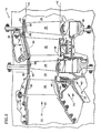
- FIG. 2 is a partial sectional view of a high pressure turbine of the type used in the gas turbine engine of Fig. 1.
- FIG. 3 is a partial isometric view of a segmented vade assembly of the type used in the high pressure turbine of Fig. 2.
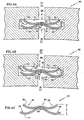
- FIG. 4a is a simplified sectional view, taken perpendicular to the longitudinal axis of the slots, of a seal in accordance with an embodiment of the invention disposed between segmented components with aligned slots.
- FIG. 4b is a simplified sectional view, taken perpendicular to the longitudinal axis of the slots, of a seal in accordance with an embodiment of the invention disposed between segmented components with misaligned slots.
- FIG. 4c is a simplified sectional view of a gap bridging assembly of FIGS. 4a and 4b prior to installation.
- FIG. 2 An exemplary turbine 16 of a gas turbine engine 10 is illustrated in Fig. 2.
- the high temperature combustion gases 22 discharge rearward from the combustor 14, at a pressure (P1), to an annular duct 24 defined by an inner periphery 42 and an outer periphery 44.
- Stationary vanes 36 guide the combustion gases 22 to rotating blades 34, extending radially outwardly from rotor disks 46.
- the vanes 36 span radially between inner 48 and outer 50 shrouds, which are suspended from an inner support 52 and/or outer casing 38 structures.
- Inner seals 54 restrict leakage of the combustion gases 22 from radially beneath the vanes 36 at the inner periphery 42.
- Outer seals 56 restrict leakage of the combustion gases 22 from radially above tips 58 of the blades 34 at the outer periphery 44.
- each of the above-described components must be actively cooled, because the combustion gas 22 temperature typically exceeds the melting temperatures of the components' base alloy.
- relatively low temperature compressor air 40 is distributed from the compressor 12 (Fig. 1), at a pressure (P2), to the inner 42 and outer 44 duct peripheries and away from the annular duct 24.
- the compressor air 40 pressure (P2) is maintained at a higher level than the combustion gas 22 pressure (P1) in order to allow compressor air 40 at pressure (P2) to flow through turbine 16 components and provide active cooling, thus preventing overheating and premature oxidation of the components.
- Seals ensure a typical pressure ratio (P2:P1) of approximately 1.03, but certainly greater than 1.0, exists during all engine operating conditions.
- Circumferentially segmented components such as the vanes 36, inner seals 54, outer seals 56 and the like, include a seal 60 between adjacent segments.
- a seal 60 in accordance with an embodiment of the invention contains bridging assemblies 62 that fit into axial and/or radial slots 64 machined into a mate face 66 of the vanes 36.
- a gap 38 between the vanes 36 typically between 0.010 inch (0.254 mm). and 0.030 inch (0.762 mm), depending on the size of the components, accounts for thermal growth and reduces TMF.
- the slots 64 face one another and are open to the gap 68.
- the bridging assemblies 62 fit into the slots 64, while spanning across the gap 68.
- a segmented component seal 60 is generally illustrated in Figs. 4a-4c.
- Opposed slots 64 are open to a gap 68 and each contain a longitudinal axis 70, an upstream surface 72 proximate a first chamber 74 and a downstream surface 76 proximate a second chamber 78. Although the upstream 72 and downstream 76 surfaces are shown parallel in the illustration, they could also converge or diverge away from the gap 68.
- the slots 64 have an opening width (W) of between about 0.030 inch (0.762 mm) and 0.060 inch (1.524 mm).
- the slots 64 are preferably aligned as illustrated in Fig.
- the slot axis 70 is linear, but a curvilinear slot axis 70 may also be used.
- the slots are produced by casting, abrasive machining, electrodischarge machining, or other suitable means.
- the bridging assembly 62 comprises first 80 and second 82 bridging elements that fit into the slots 64 and contain a sectional profile, transverse to the longitudinal slot axis 64 that is wave shaped.
- a central crest portion 84 is disposed between two trough portions 86 at the profile ends.
- the bridging elements 80, 82 nest about their crest portions 84 and may be affixed to one another via a joint 88 by any suitable process such as, conventional welding, resistance welding, brazing or the like.
- assembly and disassembly are simplified, but may still be accomplished without affixing.
- the troughs 86 of the first 80 and second 82 bridging elements are sprung apart and do not nest together.
- a free height (H) of the uninstalled bridging elements 80, 82 is slightly larger than the opening width (W) of the slot 64.
- the free height (H) is between 0.005 inch (0.127 mm) and 0.020 inch (0.508 mm) larger than the opening width (W).
- the bridging elements 80, 82 are made of a material with suitable low temperature ductility and high temperature strength.
- a Nickel or Cobalt based alloy strip approximately 0.010 inch (0.254 mm) thick is used.
- lower temperature materials may be used. Stamping, progressive rolling or other suitable forming process may be used to form the profile of the strip.
- the trough portions 86 are compressed together slightly and resiliently sprung into the slots 64 during assembly.
- the interference fit between the bridging elements 80, 82 and the upstream 80 and downstream 82 surfaces creates four independent leakage restrictions 90.
- the multiple restrictions 90 significantly reduce leakage from the first chamber 74 to the second chamber 78.
- the multiple restrictions 90 remain intact, even if the slots 64 are slightly misaligned.
- the wave shaped profile of the bridging elements 80, 82 creates constant contact with the slots 64 despite the assembly direction, it is preferable to install the crest portions 84 so they rise in the direction of the higher pressure first chamber 74.
Landscapes
- Engineering & Computer Science (AREA)
- General Engineering & Computer Science (AREA)
- Mechanical Engineering (AREA)
- Turbine Rotor Nozzle Sealing (AREA)
- Gasket Seals (AREA)
Abstract
Description
- The invention relates to gas turbine engine components in general, and specifically to a seal for preventing leakage of high pressure air or other fluids between segmented components used in such engines.
- As illustrated in FIG. 1, a
gas turbine engine 10 comprises one or moreforward compressor sections 12, acentral combustor section 14 and one or morerearward turbine sections 16. Theengine 10 operates by compressingambient air 18 with thecompressors 12, adding fuel upstream of thecombustor 14 and burning a fuel-air mixture 20 in thecombustor 14. Hightemperature combustion gases 22 are directed axially rearward from thecombustor 14, through anannular duct 24 disposed in theturbines 16. Thecombustion gases 22 interact with one ormore turbine rotors 26, outer portions of which are disposed in theduct 24. Theturbine rotors 26 are coupled tocompressor rotors 28 viaconcentric shafts 30 rotating about a centrallongitudinal axis 32 of theengine 10. Gas turbine engines are known to power aircraft, ships and electrical generators. - Extending into the
annular gas duct 24 are alternating circumferential stages of rotatingblades 34 andstationary vanes 36. Thestationary vanes 36 extend radially inwardly from acasing structure 38 surrounding theturbines 16. To prevent oxidation of thevanes 36 and other stationary components due to thehot combustion gases 22, lowtemperature compressor air 40 is directed radially inboard and outboard of theduct 24 to the components. Thecompressor air 40 is maintained at a higher pressure than thecombustion gas 22 pressure, to ensure a continuous supply ofcompressor air 40 reaches the components. - Because stationary components such as vanes, shrouds, supports and the like are subject to extreme temperature gradients, they can develop cracks due to thermal mechanical fatigue (TMF). To reduce the occurrence of TMF induced cracking, these components are typically installed in semi annular segments distributed circumferentially about the engine's longitudinal axis. The segmented components are uncoupled from one another, thus allowing them to expand and contract independently. In addition to their improved TMF resistance, segmented components are also less expensive to repair and/or replace after extended use.
- Despite the aforementioned benefits, axial and radial gaps must be included between adjacent components to allow for thermal expansion. These gaps require sealing to ensure an adequate pressure differential exists between the compressor air and the combustion gas. Maintaining a compressor air pressure that is greater than the combustion gas pressure ensures a continuous flow of compressor air and prevents backflow of the combustion gas. Excessive leakage of the compressor air may cause premature oxidation of the components and can increase the engine's fuel burn. With jet fuel accounting for up to sixty five percent of the operating expense of a commercial airliner, any reduction in fuel burn is beneficial.
- Various seal configurations are known to restrict leakage of a pressurized fluid through a gap between two components. Feather seals are the type most commonly used between segmented components in gas turbine engines. Feather seals comprise a slot in the adjacent components that are open to the gap, and a bridging element disposed in the slots, spanning across the gap.
- Flat bridging elements, such as those disclosed in
U.S. patent number 5,154,577 to Kellock, et al , are fit into the adjoining slots. They depend on the higher-pressure compressor air to seat the bridging elements against the slots to form the seal. Assembly damage, misaligned slots, slot surface finish and low compressor air pressure may negatively affect the performance of flat bridging elements. - Resilient bridging elements, such as those disclosed in
U.S. patent number 4,537,024 to Grosjean , are press fit into the adjoining slots. They rely on the contact pressure between the bridging element and the slot being greater than the compressor air pressure to form the seal. However, the single loop ends of the bridging elements offer limited contact pressure with the slot and are subject to compression about their minor axis. - Although misaligned slots, slot surface finish and low compressor air pressure have a less negative impact on resilient bridging elements, feather seal improvement is still needed.
- In accordance with the present invention, there is provided a seal for restricting leakage of a high-pressure fluid from a first chamber, through a gap between two adjoining components, to a second chamber.
- According to an embodiment of the seal, a slot is formed in each of the two components. The slots face one another and are open to the gap. Each slot contains a longitudinal axis, an upstream surface proximate the first chamber and a downstream surface proximate the second chamber. Disposed in the slots and bridging the gap are first and second bridging elements. Each bridging element contains a sectional profile, transverse to the longitudinal slot axis, that is wave shaped. Each bridging element further contains a crest portion disposed between two trough portions and the crest portions nest together. The bridging elements span the gap between the two components, the trough portions are disposed in the slots and the crest portions are disposed in the gap.
- A primary feature of the seal is the wave shaped profile of the bridging elements. The wave shape increases the contact force between the ends of the bridging element and the slot surfaces.
- A primary advantage of the seal is an increased leakage restriction over conventional seals with minimum increase in weight and cost.
- Other details of the seal according to the present invention, as well as other objects and advantages attendant thereto, are set forth in the following detailed description and the accompanying drawings wherein like reference numerals depict like elements.
- FIG. 1 is a simplified sectional view of an axial flow gas turbine engine.
- FIG. 2 is a partial sectional view of a high pressure turbine of the type used in the gas turbine engine of Fig. 1.
- FIG. 3 is a partial isometric view of a segmented vade assembly of the type used in the high pressure turbine of Fig. 2.
- FIG. 4a is a simplified sectional view, taken perpendicular to the longitudinal axis of the slots, of a seal in accordance with an embodiment of the invention disposed between segmented components with aligned slots.
- FIG. 4b is a simplified sectional view, taken perpendicular to the longitudinal axis of the slots, of a seal in accordance with an embodiment of the invention disposed between segmented components with misaligned slots.
- FIG. 4c is a simplified sectional view of a gap bridging assembly of FIGS. 4a and 4b prior to installation.
- An
exemplary turbine 16 of agas turbine engine 10 is illustrated in Fig. 2. The hightemperature combustion gases 22 discharge rearward from thecombustor 14, at a pressure (P1), to anannular duct 24 defined by aninner periphery 42 and anouter periphery 44.Stationary vanes 36 guide thecombustion gases 22 to rotatingblades 34, extending radially outwardly fromrotor disks 46. Thevanes 36 span radially between inner 48 and outer 50 shrouds, which are suspended from aninner support 52 and/orouter casing 38 structures.Inner seals 54 restrict leakage of thecombustion gases 22 from radially beneath thevanes 36 at theinner periphery 42.Outer seals 56 restrict leakage of thecombustion gases 22 from radially abovetips 58 of theblades 34 at theouter periphery 44. - Those skilled in the art will appreciate that each of the above-described components must be actively cooled, because the
combustion gas 22 temperature typically exceeds the melting temperatures of the components' base alloy. For cooling purposes, relatively lowtemperature compressor air 40 is distributed from the compressor 12 (Fig. 1), at a pressure (P2), to the inner 42 and outer 44 duct peripheries and away from theannular duct 24. Thecompressor air 40 pressure (P2) is maintained at a higher level than thecombustion gas 22 pressure (P1) in order to allowcompressor air 40 at pressure (P2) to flow throughturbine 16 components and provide active cooling, thus preventing overheating and premature oxidation of the components. Seals ensure a typical pressure ratio (P2:P1) of approximately 1.03, but certainly greater than 1.0, exists during all engine operating conditions. - Circumferentially segmented components such as the
vanes 36,inner seals 54,outer seals 56 and the like, include aseal 60 between adjacent segments. As best illustrated in Fig. 3, aseal 60 in accordance with an embodiment of the invention contains bridgingassemblies 62 that fit into axial and/orradial slots 64 machined into a mate face 66 of thevanes 36. With thevanes 36 installed, agap 38 between thevanes 36 typically between 0.010 inch (0.254 mm). and 0.030 inch (0.762 mm), depending on the size of the components, accounts for thermal growth and reduces TMF. Theslots 64 face one another and are open to thegap 68. Thebridging assemblies 62 fit into theslots 64, while spanning across thegap 68. Althoughsegmented vanes 36 are illustrated in the figure, other segmented component seals are similarly constructed. - Further details of a
segmented component seal 60 according to an embodiment of the invention are generally illustrated in Figs. 4a-4c.Opposed slots 64 are open to agap 68 and each contain alongitudinal axis 70, anupstream surface 72 proximate afirst chamber 74 and adownstream surface 76 proximate asecond chamber 78. Although the upstream 72 and downstream 76 surfaces are shown parallel in the illustration, they could also converge or diverge away from thegap 68. Typically, theslots 64 have an opening width (W) of between about 0.030 inch (0.762 mm) and 0.060 inch (1.524 mm). Theslots 64 are preferably aligned as illustrated in Fig. 4a, but in some instances they may be slightly misaligned due to manufacturing tolerances as illustrated in Fig. 4b. Preferably, theslot axis 70 is linear, but acurvilinear slot axis 70 may also be used. The slots are produced by casting, abrasive machining, electrodischarge machining, or other suitable means. - The bridging
assembly 62 comprises first 80 and second 82 bridging elements that fit into theslots 64 and contain a sectional profile, transverse to thelongitudinal slot axis 64 that is wave shaped. Acentral crest portion 84 is disposed between twotrough portions 86 at the profile ends. The bridgingelements 80, 82 nest about theircrest portions 84 and may be affixed to one another via a joint 88 by any suitable process such as, conventional welding, resistance welding, brazing or the like. By affixing thebridging elements 80, 82 together, assembly and disassembly are simplified, but may still be accomplished without affixing. Thetroughs 86 of the first 80 and second 82 bridging elements are sprung apart and do not nest together. - As may best be seen in FIG. 4C, a free height (H) of the uninstalled bridging
elements 80, 82 is slightly larger than the opening width (W) of theslot 64. Preferably, the free height (H) is between 0.005 inch (0.127 mm) and 0.020 inch (0.508 mm) larger than the opening width (W). These dimensions are exemplary only and the actual sizes may vary for each specific application. The bridgingelements 80, 82 are made of a material with suitable low temperature ductility and high temperature strength. Preferably, a Nickel or Cobalt based alloy strip approximately 0.010 inch (0.254 mm) thick is used. For lower temperature applications such as in the compressor, lower temperature materials may be used. Stamping, progressive rolling or other suitable forming process may be used to form the profile of the strip. - Since the free height (H) is greater than the opening width (W), the
trough portions 86 are compressed together slightly and resiliently sprung into theslots 64 during assembly. The interference fit between the bridgingelements 80, 82 and the upstream 80 and downstream 82 surfaces creates fourindependent leakage restrictions 90. Themultiple restrictions 90 significantly reduce leakage from thefirst chamber 74 to thesecond chamber 78. As may also be seen in FIG. 4B, themultiple restrictions 90 remain intact, even if theslots 64 are slightly misaligned. Although the wave shaped profile of thebridging elements 80, 82 creates constant contact with theslots 64 despite the assembly direction, it is preferable to install thecrest portions 84 so they rise in the direction of the higher pressurefirst chamber 74. - While the present invention has been described in the context of specific embodiments thereof, other alternatives, modifications and variations will become apparent to those skilled in the art having read the foregoing description. Accordingly, it is intended to embrace those alternatives, modifications and variations as fall within the broad scope of the appended claims.
Claims (16)
- A seal for restricting leakage of a fluid from a first chamber, through a gap between two spaced components, to a second chamber, comprising:a slot in each of the components, wherein the slots are open to the gap and each slot contains a longitudinal axis;a bridging assembly containing a first and a second bridging element, wherein said elements each contain a sectional profile, transverse to the longitudinal slot axis, that is wave shaped and includes a crest portion disposed between two trough portions, andwherein the crest portion of the first bridging element nests together with the crest portion of the second bridging element; andwherein the bridging assembly spans between the two components with the trough portions being disposed in the slots and the crest portions being disposed in the gap.
- The seal of claim 1 wherein each slot contains an upstream surface proximate the first chamber and a downstream surface proximate the second chamber, and the first bridging element contacts the upstream surfaces and the second bridging element contacts the downstream surfaces.
- The seal of claim 2 wherein the trough portions are resiliently sprung into the slots, forming an interference fit between the bridging elements and the upstream and downstream surfaces.
- The seal of claim 3 wherein the crest portions rise toward the first chamber.
- The seal of any preceding claim wherein said first and second bridging elements are affixed to one another at the crest portions.
- The seal of claim 5 wherein the first and second bridging elements are affixed at said crest portions by welding.
- The seal of claim 6 wherein the trough portions of the first and second bridging elements are spaced apart from one another.
- The seal of any preceding claim wherein the bridging elements are made of a nickel based alloy strip.
- The seal of any preceding claim wherein the longitudinal axis of each slot is linear.
- The seal of any preceding claim wherein the two components are turbine vanes.
- The seal of any preceding claim wherein the fluid is compressor air.
- A gap bridging assembly comprising:a first and a second resilient element, wherein said resilient elements each contain a sectional profile, transverse to a longitudinal assembly axis, that is wave shaped and includes a central, crest portion disposed between two end, trough portions; andwherein the crest portions of the first and the second resilient elements nest together.
- The gap bridging assembly of claim 12 wherein the first and second resilient elements are affixed to one another at said crest portions.
- The gap bridging assembly of claim 13 wherein the first and second resilient elements are affixed by a weld joint.
- The gap bridging assembly of claim 14 wherein the trough portions of the first and second resilient elements are spaced apart from one another.
- The gap bridging assembly of claim 15 wherein the resilient elements are made of a nickel based alloy strip.
Applications Claiming Priority (1)
| Application Number | Priority Date | Filing Date | Title |
|---|---|---|---|
| US11/371,882 US7316402B2 (en) | 2006-03-09 | 2006-03-09 | Segmented component seal |
Publications (3)
| Publication Number | Publication Date |
|---|---|
| EP1832716A2 true EP1832716A2 (en) | 2007-09-12 |
| EP1832716A3 EP1832716A3 (en) | 2008-05-21 |
| EP1832716B1 EP1832716B1 (en) | 2009-11-11 |
Family
ID=38070599
Family Applications (1)
| Application Number | Title | Priority Date | Filing Date |
|---|---|---|---|
| EP07250995A Not-in-force EP1832716B1 (en) | 2006-03-09 | 2007-03-09 | Segmented component seal |
Country Status (3)
| Country | Link |
|---|---|
| US (1) | US7316402B2 (en) |
| EP (1) | EP1832716B1 (en) |
| DE (1) | DE602007003125D1 (en) |
Cited By (8)
| Publication number | Priority date | Publication date | Assignee | Title |
|---|---|---|---|---|
| WO2009052875A1 (en) * | 2007-10-18 | 2009-04-30 | Federal-Mogul Sealing Systems Gmbh | Welded metal seal |
| EP2626600A3 (en) * | 2012-02-13 | 2014-01-01 | General Electric Company | Transition piece seal assembly for a turbomachine |
| WO2015112239A1 (en) | 2014-01-24 | 2015-07-30 | United Technologies Corporation | Circumferential axial segmented trough seal |
| WO2016146920A1 (en) * | 2015-03-17 | 2016-09-22 | Snecma | Assembly with sealing plates for gas turbine |
| EP3184212A3 (en) * | 2015-12-21 | 2017-11-29 | Pratt & Whitney Canada Corp. | Method of sizing a cavity in a part |
| EP3327254A1 (en) * | 2016-11-29 | 2018-05-30 | Rolls-Royce North American Technologies, Inc. | Seal assembly for gas turbine engine components |
| EP3653844A1 (en) * | 2018-11-15 | 2020-05-20 | Siemens Aktiengesellschaft | Strip seal, annular segment and method for a gas turbine |
| EP4056814A1 (en) * | 2021-03-11 | 2022-09-14 | Raytheon Technologies Corporation | Vane assembly with spring device for biasing mate face seal |
Families Citing this family (30)
| Publication number | Priority date | Publication date | Assignee | Title |
|---|---|---|---|---|
| WO2007007611A1 (en) * | 2005-07-07 | 2007-01-18 | Nok Corporation | Gasket |
| MX2008011352A (en) * | 2006-03-06 | 2008-09-23 | Alstom Technology Ltd | Gas turbine with annular heat shield and angled sealing strips. |
| US20070212214A1 (en) * | 2006-03-09 | 2007-09-13 | United Technologies Corporation | Segmented component seal |
| CH698036B1 (en) * | 2006-09-12 | 2011-11-15 | Parker Hannifin Corp | Seal assembly. |
| US8210799B1 (en) * | 2008-03-31 | 2012-07-03 | Florida Turbine Technologies, Inc. | Bi-metallic strip seal for a turbine shroud |
| FR2933160B1 (en) * | 2008-06-25 | 2010-09-10 | Commissariat Energie Atomique | ASSEMBLY COMPRISING AN INTERCAL SEAL SEAL BETWEEN TWO COMPONENTS OF DIFFERENT MEDIUM THERMAL EXPANSION COEFFICIENT, SEAL SEAL, APPLICATION TO THE SEALING OF EHT ELECTROLYSIS AND FUEL CELLS |
| US8322977B2 (en) * | 2009-07-22 | 2012-12-04 | Siemens Energy, Inc. | Seal structure for preventing leakage of gases across a gap between two components in a turbine engine |
| US8398090B2 (en) * | 2010-06-09 | 2013-03-19 | General Electric Company | Spring loaded seal assembly for turbines |
| US8727710B2 (en) | 2011-01-24 | 2014-05-20 | United Technologies Corporation | Mateface cooling feather seal assembly |
| US9534500B2 (en) * | 2011-04-27 | 2017-01-03 | Pratt & Whitney Canada Corp. | Seal arrangement for segmented gas turbine engine components |
| US20120306169A1 (en) * | 2011-06-03 | 2012-12-06 | General Electric Company | Hinge seal |
| US8544852B2 (en) | 2011-06-03 | 2013-10-01 | General Electric Company | Torsion seal |
| US20130028713A1 (en) * | 2011-07-25 | 2013-01-31 | General Electric Company | Seal for turbomachine segments |
| US9810086B2 (en) | 2011-11-06 | 2017-11-07 | General Electric Company | Asymmetric radial spline seal for a gas turbine engine |
| US8556578B1 (en) * | 2012-08-15 | 2013-10-15 | Florida Turbine Technologies, Inc. | Spring loaded compliant seal for high temperature use |
| US9771895B2 (en) * | 2012-10-17 | 2017-09-26 | United Technologies Corporation | Seal assembly for liners of exhaust nozzle |
| FR2997324B1 (en) * | 2012-10-31 | 2015-05-15 | Snecma | HIGH PERFORMANCE PERFORMING ANNULAR METAL STATIC JOINT FOR HIGH PRESSURES AND LARGE DIAMETERS |
| US9347322B2 (en) * | 2012-11-01 | 2016-05-24 | Siemens Aktiengesellschaft | Gas turbine including belly band seal anti-rotation device |
| DE102013205028A1 (en) * | 2013-03-21 | 2014-09-25 | Siemens Aktiengesellschaft | Sealing element for sealing a gap |
| JP6173811B2 (en) * | 2013-07-16 | 2017-08-02 | 三菱日立パワーシステムズ株式会社 | Seal device and gas turbine |
| US9797262B2 (en) * | 2013-07-26 | 2017-10-24 | United Technologies Corporation | Split damped outer shroud for gas turbine engine stator arrays |
| EP3039269B1 (en) | 2013-08-29 | 2020-05-06 | United Technologies Corporation | Gas turbine engine and assembly method |
| WO2015105654A1 (en) | 2014-01-08 | 2015-07-16 | United Technologies Corporation | Clamping seal for jet engine mid-turbine frame |
| DE102015201782A1 (en) * | 2015-02-02 | 2016-08-18 | MTU Aero Engines AG | Guide vane ring for a turbomachine |
| GB201514093D0 (en) * | 2015-08-10 | 2015-09-23 | Rolls Royce Plc | A Sealing Attachment for a Gas Turbine Engine |
| US10378772B2 (en) | 2017-01-19 | 2019-08-13 | General Electric Company | Combustor heat shield sealing |
| FR3065986B1 (en) * | 2017-05-02 | 2021-07-09 | Safran Aircraft Engines | ASSEMBLY FOR GAS TURBINE, ASSOCIATED GAS TURBINE |
| CN111936725B (en) * | 2018-03-30 | 2022-08-16 | 西门子能源全球两合公司 | Sealing arrangement between turbine shroud segments |
| US10927691B2 (en) * | 2019-03-21 | 2021-02-23 | Solar Turbines Incorporated | Nozzle segment air seal |
| US11773977B2 (en) | 2020-07-08 | 2023-10-03 | Saint-Gobain Performance Plastics Corporation | Bimetallic seal |
Citations (3)
| Publication number | Priority date | Publication date | Assignee | Title |
|---|---|---|---|---|
| US4537024A (en) | 1979-04-23 | 1985-08-27 | Solar Turbines, Incorporated | Turbine engines |
| EP0767329A1 (en) | 1995-10-06 | 1997-04-09 | Mtu Motoren- Und Turbinen-Union MàNchen Gmbh | Device for sealing an annular chamber |
| EP1176343A2 (en) | 2000-07-28 | 2002-01-30 | Alstom (Switzerland) Ltd | Sealing between static turbine components |
Family Cites Families (17)
| Publication number | Priority date | Publication date | Assignee | Title |
|---|---|---|---|---|
| US4311432A (en) * | 1979-11-20 | 1982-01-19 | United Technologies Corporation | Radial seal |
| US4759555A (en) * | 1985-07-25 | 1988-07-26 | Eg&G Pressure Science, Inc. | Split ring seal with slip joint |
| US5154577A (en) * | 1991-01-17 | 1992-10-13 | General Electric Company | Flexible three-piece seal assembly |
| US5125796A (en) * | 1991-05-14 | 1992-06-30 | General Electric Company | Transition piece seal spring for a gas turbine |
| US5435576A (en) * | 1992-12-28 | 1995-07-25 | Rode; John E. | Spring gasket |
| US5630593A (en) * | 1994-09-12 | 1997-05-20 | Eg&G Pressure Science, Inc. | Pressure-energized sealing rings |
| JP2941698B2 (en) * | 1995-11-10 | 1999-08-25 | 三菱重工業株式会社 | Gas turbine rotor |
| EP0922173B1 (en) * | 1996-08-29 | 2003-04-09 | Flexitallic Investments, Inc. | Gasket and method for sealing two bodies with such a gasket |
| US5709530A (en) * | 1996-09-04 | 1998-01-20 | United Technologies Corporation | Gas turbine vane seal |
| US6237921B1 (en) * | 1998-09-02 | 2001-05-29 | General Electric Company | Nested bridge seal |
| US6199871B1 (en) * | 1998-09-02 | 2001-03-13 | General Electric Company | High excursion ring seal |
| US6193240B1 (en) * | 1999-01-11 | 2001-02-27 | General Electric Company | Seal assembly |
| US6968615B1 (en) * | 2000-10-24 | 2005-11-29 | The Advanced Products Company | High temperature metallic seal |
| DE50211431D1 (en) * | 2001-09-25 | 2008-02-07 | Alstom Technology Ltd | SEALING ARRANGEMENT FOR THE DENSITY PALL REDUCTION WITHIN A FLOW ROTATION MACHINE |
| US20040239053A1 (en) * | 2001-10-29 | 2004-12-02 | Rowe Gordon D. | Seal |
| US6659472B2 (en) * | 2001-12-28 | 2003-12-09 | General Electric Company | Seal for gas turbine nozzle and shroud interface |
| JP2004060842A (en) * | 2002-07-31 | 2004-02-26 | Nichias Corp | gasket |
-
2006
- 2006-03-09 US US11/371,882 patent/US7316402B2/en not_active Expired - Lifetime
-
2007
- 2007-03-09 EP EP07250995A patent/EP1832716B1/en not_active Not-in-force
- 2007-03-09 DE DE602007003125T patent/DE602007003125D1/en active Active
Patent Citations (3)
| Publication number | Priority date | Publication date | Assignee | Title |
|---|---|---|---|---|
| US4537024A (en) | 1979-04-23 | 1985-08-27 | Solar Turbines, Incorporated | Turbine engines |
| EP0767329A1 (en) | 1995-10-06 | 1997-04-09 | Mtu Motoren- Und Turbinen-Union MàNchen Gmbh | Device for sealing an annular chamber |
| EP1176343A2 (en) | 2000-07-28 | 2002-01-30 | Alstom (Switzerland) Ltd | Sealing between static turbine components |
Cited By (14)
| Publication number | Priority date | Publication date | Assignee | Title |
|---|---|---|---|---|
| WO2009052875A1 (en) * | 2007-10-18 | 2009-04-30 | Federal-Mogul Sealing Systems Gmbh | Welded metal seal |
| US9115808B2 (en) | 2012-02-13 | 2015-08-25 | General Electric Company | Transition piece seal assembly for a turbomachine |
| EP2626600A3 (en) * | 2012-02-13 | 2014-01-01 | General Electric Company | Transition piece seal assembly for a turbomachine |
| EP3102810A4 (en) * | 2014-01-24 | 2017-12-06 | United Technologies Corporation | Circumferential axial segmented trough seal |
| WO2015112239A1 (en) | 2014-01-24 | 2015-07-30 | United Technologies Corporation | Circumferential axial segmented trough seal |
| US10683768B2 (en) | 2014-01-24 | 2020-06-16 | Raytheon Technologies Corporation | Circumferential axial segmented trough seal |
| WO2016146920A1 (en) * | 2015-03-17 | 2016-09-22 | Snecma | Assembly with sealing plates for gas turbine |
| EP3184212A3 (en) * | 2015-12-21 | 2017-11-29 | Pratt & Whitney Canada Corp. | Method of sizing a cavity in a part |
| US10822988B2 (en) | 2015-12-21 | 2020-11-03 | Pratt & Whitney Canada Corp. | Method of sizing a cavity in a part |
| EP3327254A1 (en) * | 2016-11-29 | 2018-05-30 | Rolls-Royce North American Technologies, Inc. | Seal assembly for gas turbine engine components |
| US10301955B2 (en) | 2016-11-29 | 2019-05-28 | Rolls-Royce North American Technologies Inc. | Seal assembly for gas turbine engine components |
| EP3653844A1 (en) * | 2018-11-15 | 2020-05-20 | Siemens Aktiengesellschaft | Strip seal, annular segment and method for a gas turbine |
| EP4056814A1 (en) * | 2021-03-11 | 2022-09-14 | Raytheon Technologies Corporation | Vane assembly with spring device for biasing mate face seal |
| US11649732B2 (en) | 2021-03-11 | 2023-05-16 | Raytheon Technologies Corporation | Vane assembly with spring device for biasing mate face seal |
Also Published As
| Publication number | Publication date |
|---|---|
| DE602007003125D1 (en) | 2009-12-24 |
| US7316402B2 (en) | 2008-01-08 |
| EP1832716B1 (en) | 2009-11-11 |
| US20070210536A1 (en) | 2007-09-13 |
| EP1832716A3 (en) | 2008-05-21 |
Similar Documents
| Publication | Publication Date | Title |
|---|---|---|
| EP1832716B1 (en) | Segmented component seal | |
| EP1832715B1 (en) | Gas turbine segmented component seal | |
| CA2532704C (en) | Gas turbine engine shroud sealing arrangement | |
| US11092029B2 (en) | Shroud hanger assembly | |
| US6733233B2 (en) | Attachment of a ceramic shroud in a metal housing | |
| EP2543825B1 (en) | Gas turbine shroud arrangement | |
| US8419356B2 (en) | Turbine seal assembly | |
| US8376697B2 (en) | Gas turbine sealing apparatus | |
| US8257028B2 (en) | Turbine nozzle segment | |
| US20060082074A1 (en) | Circumferential feather seal | |
| US20120274034A1 (en) | Seal arrangement for segmented gas turbine engine components | |
| US20090169369A1 (en) | Turbine nozzle segment and assembly | |
| US20100074730A1 (en) | Gas turbine sealing apparatus | |
| CN1421593A (en) | Blocking seal apparatus with heat adaptability | |
| US20120263580A1 (en) | Flexible seal for turbine engine | |
| EP1132576B1 (en) | Turbine shroud comprising an apparatus for minimizing thermal gradients and method for assembling a gas turbine engine including such a shroud | |
| US7837435B2 (en) | Stator damper shim | |
| US11131215B2 (en) | Turbine shroud cartridge assembly with sealing features | |
| GB2606552A (en) | Sealing system for gas turbine engine | |
| US20090169376A1 (en) | Turbine Nozzle Segment and Method for Repairing a Turbine Nozzle Segment |
Legal Events
| Date | Code | Title | Description |
|---|---|---|---|
| PUAI | Public reference made under article 153(3) epc to a published international application that has entered the european phase |
Free format text: ORIGINAL CODE: 0009012 |
|
| AK | Designated contracting states |
Kind code of ref document: A2 Designated state(s): AT BE BG CH CY CZ DE DK EE ES FI FR GB GR HU IE IS IT LI LT LU LV MC MT NL PL PT RO SE SI SK TR |
|
| AX | Request for extension of the european patent |
Extension state: AL BA HR MK YU |
|
| PUAL | Search report despatched |
Free format text: ORIGINAL CODE: 0009013 |
|
| AK | Designated contracting states |
Kind code of ref document: A3 Designated state(s): AT BE BG CH CY CZ DE DK EE ES FI FR GB GR HU IE IS IT LI LT LU LV MC MT NL PL PT RO SE SI SK TR |
|
| AX | Request for extension of the european patent |
Extension state: AL BA HR MK RS |
|
| RIC1 | Information provided on ipc code assigned before grant |
Ipc: F01D 11/00 20060101AFI20070608BHEP Ipc: F16J 15/08 20060101ALI20080415BHEP |
|
| 17P | Request for examination filed |
Effective date: 20080619 |
|
| 17Q | First examination report despatched |
Effective date: 20080805 |
|
| AKX | Designation fees paid |
Designated state(s): DE GB |
|
| GRAP | Despatch of communication of intention to grant a patent |
Free format text: ORIGINAL CODE: EPIDOSNIGR1 |
|
| GRAS | Grant fee paid |
Free format text: ORIGINAL CODE: EPIDOSNIGR3 |
|
| GRAA | (expected) grant |
Free format text: ORIGINAL CODE: 0009210 |
|
| AK | Designated contracting states |
Kind code of ref document: B1 Designated state(s): DE GB |
|
| REG | Reference to a national code |
Ref country code: GB Ref legal event code: FG4D |
|
| REF | Corresponds to: |
Ref document number: 602007003125 Country of ref document: DE Date of ref document: 20091224 Kind code of ref document: P |
|
| PLBE | No opposition filed within time limit |
Free format text: ORIGINAL CODE: 0009261 |
|
| STAA | Information on the status of an ep patent application or granted ep patent |
Free format text: STATUS: NO OPPOSITION FILED WITHIN TIME LIMIT |
|
| 26N | No opposition filed |
Effective date: 20100812 |
|
| PGFP | Annual fee paid to national office [announced via postgrant information from national office to epo] |
Ref country code: DE Payment date: 20130306 Year of fee payment: 7 Ref country code: GB Payment date: 20130306 Year of fee payment: 7 |
|
| REG | Reference to a national code |
Ref country code: DE Ref legal event code: R119 Ref document number: 602007003125 Country of ref document: DE |
|
| GBPC | Gb: european patent ceased through non-payment of renewal fee |
Effective date: 20140309 |
|
| REG | Reference to a national code |
Ref country code: DE Ref legal event code: R119 Ref document number: 602007003125 Country of ref document: DE Effective date: 20141001 |
|
| PG25 | Lapsed in a contracting state [announced via postgrant information from national office to epo] |
Ref country code: DE Free format text: LAPSE BECAUSE OF NON-PAYMENT OF DUE FEES Effective date: 20141001 Ref country code: GB Free format text: LAPSE BECAUSE OF NON-PAYMENT OF DUE FEES Effective date: 20140309 |